EP3227498B1 - Ground engaging tool - Google Patents
Ground engaging tool Download PDFInfo
- Publication number
- EP3227498B1 EP3227498B1 EP15805704.2A EP15805704A EP3227498B1 EP 3227498 B1 EP3227498 B1 EP 3227498B1 EP 15805704 A EP15805704 A EP 15805704A EP 3227498 B1 EP3227498 B1 EP 3227498B1
- Authority
- EP
- European Patent Office
- Prior art keywords
- lock
- tool
- ground engaging
- detent
- opening
- Prior art date
- Legal status (The legal status is an assumption and is not a legal conclusion. Google has not performed a legal analysis and makes no representation as to the accuracy of the status listed.)
- Active
Links
- 230000000712 assembly Effects 0.000 description 5
- 238000000429 assembly Methods 0.000 description 5
- 239000000463 material Substances 0.000 description 5
- 238000005299 abrasion Methods 0.000 description 4
- 239000013013 elastic material Substances 0.000 description 3
- 239000006260 foam Substances 0.000 description 3
- 230000014759 maintenance of location Effects 0.000 description 2
- 239000002184 metal Substances 0.000 description 2
- 238000000034 method Methods 0.000 description 2
- 238000005065 mining Methods 0.000 description 2
- 238000012986 modification Methods 0.000 description 2
- 230000004048 modification Effects 0.000 description 2
- 230000006835 compression Effects 0.000 description 1
- 238000007906 compression Methods 0.000 description 1
- 238000010276 construction Methods 0.000 description 1
- 239000003292 glue Substances 0.000 description 1
- 238000003780 insertion Methods 0.000 description 1
- 230000037431 insertion Effects 0.000 description 1
- 229910052755 nonmetal Inorganic materials 0.000 description 1
- 230000001012 protector Effects 0.000 description 1
- 239000011435 rock Substances 0.000 description 1
Images


Classifications
-
- E—FIXED CONSTRUCTIONS
- E02—HYDRAULIC ENGINEERING; FOUNDATIONS; SOIL SHIFTING
- E02F—DREDGING; SOIL-SHIFTING
- E02F9/00—Component parts of dredgers or soil-shifting machines, not restricted to one of the kinds covered by groups E02F3/00 - E02F7/00
- E02F9/28—Small metalwork for digging elements, e.g. teeth scraper bits
- E02F9/2808—Teeth
- E02F9/2816—Mountings therefor
- E02F9/2833—Retaining means, e.g. pins
- E02F9/2841—Retaining means, e.g. pins resilient
-
- E—FIXED CONSTRUCTIONS
- E02—HYDRAULIC ENGINEERING; FOUNDATIONS; SOIL SHIFTING
- E02F—DREDGING; SOIL-SHIFTING
- E02F9/00—Component parts of dredgers or soil-shifting machines, not restricted to one of the kinds covered by groups E02F3/00 - E02F7/00
- E02F9/28—Small metalwork for digging elements, e.g. teeth scraper bits
- E02F9/2808—Teeth
- E02F9/2816—Mountings therefor
- E02F9/2833—Retaining means, e.g. pins
Definitions
- the present disclosure relates generally to a ground engaging tool and, more particularly, to a ground engaging tool that is removably attachable to an earth-working machine.
- Earth-working machines such as, for example, excavators, wheel loaders, hydraulic mining shovels, cable shovels, bucket wheels, bulldozers, and draglines, are generally used for digging or ripping into the earth or rock and/or moving loosened work material from one place to another at a worksite.
- These earth-working machines include various earth-working implements, such as a bucket or a blade, for excavating or moving the work material. These implements can be subjected to extreme wear from the abrasion and impacts experienced during the earth-working applications.
- ground engaging tools such as teeth, edge protectors, and other wear members, can be provided on the earth-working implements in the areas where the most damaging abrasions and impacts occur.
- These ground engaging tools are removably attached to the implements using customized retainer systems, so that worn or damaged ground engaging tools can be readily removed and replaced with new ground engaging tools.
- the system includes a rotating lock having a slot for receiving a post of an adapter that is mounted to or part of a work tool.
- the lock is positioned in a retainer bushing, which is positioned in a lock cavity of a ground engaging tool.
- the present invention seeks to overcome the problems associated with such known retainer systems.
- the present disclosure is directed to a lock for a ground engaging tool and a ground engaging tool assembly comprising such a lock as set out in the claims.
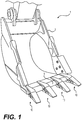
- Fig. 1 illustrates an excavator bucket assembly 1 as an exemplary implement of an earth-working machine.
- Excavator bucket assembly 1 includes a bucket 2 used for excavating work material in a known manner.
- Bucket 2 may include a variety of ground engaging tools.
- bucket 2 may include a plurality of tooth assemblies 10, as ground engaging tools, attached to a base edge 5 of bucket 2. Tooth assemblies 10 may be secured to bucket 2 employing retainer systems according to the present disclosure. While various embodiments of the present disclosure will be described in connection with a particular ground engaging tool assembly (e.g., tooth assembly 10), it should be understood that the present disclosure may be applied to, or used in connection with, any other type of ground engaging tools or components. Further, it should be understood that one or more features described in connection with one embodiment can be implemented in any of the other disclosed embodiments unless otherwise specifically noted.
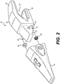
- tooth assembly 10 may include an adapter 20 configured to engage base edge 5 of bucket 2 or other suitable support structure of an implement. Tooth assembly 10 may also include a ground-engaging tip 30 configured to be removably attached to adapter 20. Tooth assembly 10 may further include a lock 60 configured to secure tip 30 to adapter 20. Tip 30 may endure the majority of the impact and abrasion caused by engagement with work material, and wear down more quickly and break more frequently than adapter 20. Consequently, multiple tips 30 may be attached to adapter 20, worn down, and replaced before adapter 20 needs to be replaced. As will be detailed herein, various exemplary embodiments of lock 60, consistent with the present disclosure, may facilitate attachment and detachment of ground engaging tools to and from the support structure of an implement.
- Adapter 20 may include a pair of first and second mounting legs 26, 28 defining a recess 27 therebetween for receiving base edge 5.
- Adapter 20 may be secured in place on base edge 5 by attaching first mounting leg 26 and second mounting leg 28 to base edge 5 using any suitable connection method.
- mounting legs 26 and 28 and base edge 5 may have corresponding apertures (not shown) through which any suitable fasteners such as bolts or rivets may be inserted to hold adapter 20 in place.
- mounting legs 26 and 28 may be welded to the corresponding top and bottom surfaces of base edge 5. Any other connection method and/or configuration known in the art may be used alternatively or additionally.
- an adapter may be configured to use any of the retainer systems disclosed herein to secure the adapter to a suitable support structure of an implement.
- Adapter 20 may include a nose 21 extending in a forward direction. Nose 21 may be configured to be received in a mounting cavity 35 of tip 30, shown in Fig. 3 . Nose 21 may be configured to support tip 30 during use of bucket 2 and to facilitate retention of tip 30 on nose 21 when bearing the load of the work material. Nose 21 may include an integral post 23 extending from each lateral side 22, 24. Post 23 may have various shapes and sizes. In one exemplary embodiment, as shown in Fig. 2 , post 23 may have a frustoconical shape. As will be described in more detail herein, posts 23 may cooperate with locks 60 to secure tip 30 to adapter 20.
- tip 30 may include an interior surface 100, which may define mounting cavity 35, an exterior surface 101, and a rear surface 102, which may connect interior surface 100 to exterior surface 101.
- exterior surface 101 may generally taper as it extends forward.
- an upper portion 32 of exterior surface 101 may slope downward as it extends forward, and a lower portion 38 of exterior surface 101 may extend generally upward as it extends forward.
- lower portion 38 may extend generally straight or downward as it extends forward.
- exterior surface 101 At its forward end, substantially opposite of rear surface 102, exterior surface 101 may define a wedge-shaped front edge 31 of tip 30.
- tip 30 may be secured to adapter 20 via lock 60.
- Tip 30 may have various configurations for accommodating adapter 20 and lock 60.
- interior surface 100 may define slots 103 recessed into tip 30's lateral sides 37 to receive posts 23 of adapter 20.
- a lock opening surface 104 in each of tip 30's lateral sides 37 may define a lock opening 40, into which one of slots 103 may extend from rear surface 102.
- Lock opening 40 may extend from interior surface 100, through side 37, to exterior surface 101, and may house lock 60 and a post 23 received via the one of slots 103. While the exemplary embodiment shown in Figs.
- tip 30 may have different numbers and/or arrangements of lock opening surfaces 104 (and lock openings 40).
- tip 30 may have more than one lock opening surface 104 (and lock opening 40) on each lateral side 37, or may have a lock opening surface 104 (and lock opening 40) on only a single lateral side 37.
- lock opening surface 104 may include a generally circular inner portion 105 and a generally circular outer portion 106.
- Inner portion may be adjacent interior surface 100, while outer portion 106 may be adjacent exterior surface 101.
- portions 105 and 106 may be generally cylindrical.
- outer portion 106 may have a smaller diameter than inner portion 105 to prevent lock 60 from passing all the way through lock opening 40.
- one or both of portions 105 and 106 may be generally frustoconical to prevent lock 60 from passing all the way through lock opening 40.
- inner portion 105 may be configured to guide and intermittently inhibit rotation of lock 60 within lock opening 40.
- inner portion 105 may define a groove 107 in tip 30 positioned circumferentially around lock opening 40.
- Groove 107 may interact with one or more detent projections 67 of lock 60 to ensure lock 60 rotates about lock rotation axis 65 (referring to Figs. 4 and 6 ) and does not fall out of lock opening 40.
- groove 107 may interact with the one or more detent projections 67 to ensure lock 60 does not fall out of lock opening 40 regardless of how lock 60 is rotated.
- inner portion 105 may define one or more channels (not shown) extending from groove 107 to interior surface 100 to allow lock 60 to fall out of lock opening 40 when lock 60 is rotated to certain positions in which the one or more detent projections 67 align with the one or more channels.
- Inner portion 105 may also define at least one detent recess 77 in tip 30 along groove 107, which may interact with one or more detent projections 67 of lock 60 to inhibit rotation of lock 60 when engaged by the one or more detent projections 67.
- inner portion 105 may define two detent recesses 77 in tip 30 along groove 107. These detent recesses 77 may be spaced apart from one another by approximately 180 degrees to intermittently inhibit rotation of lock 60 at 180 degree intervals.
- detent recesses 77 may be shaped like detent projections 67 to optimize engagement with detent projections 67.
- detent recesses 77 may be at least partially sphere-shaped to optimize engagement with detent projections 67 that are at least partially sphere-shaped.
- detent recesses 77 may be otherwise shaped.
- detent recesses 77 may be at least partially football- or bullet-shaped if detent projections 67 are at least partially football- or bullet-shaped.
- lock opening 40 may house and allow rotation of lock 60 about lock rotation axis 65.
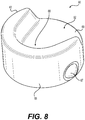
- lock 60 may include a head portion 80, which may have a top section 108 and a bottom section 109.
- lock 60 may include a C-shaped skirt 63 extending from bottom section 109, and defining a lock slot 62 for receiving post 23.
- skirt 63 may define an outer surface 66 of lock 60, which may be configured to be rotatably received in lock opening 40 of tip 30.
- outer surface 66 may have substantially the same cylindrical (as shown) or frustoconical profile as lock opening 40.
- outer surface 66 may be circular and extend circumferentially around lock rotation axis 65. While head portion 80's portion of outer surface 66 may extend completely around lock rotation axis 65, skirt 63's portion of outer surface 66 may extend only partway around lock rotation axis 65.
- lock 60 With outer surface 66 of lock 60 so configured, lock 60 may be seated within lock opening 40 with top section 108's portion of outer surface 66 mated to outer portion 106 of lock opening 40, and the remainder of outer surface 66 mated to inner portion 105 of lock opening 40.
- lock rotation axis 65 may be approximately perpendicular to the part of exterior surface 101 of tip 30 surrounding lock opening 40.
- lock rotation axis 65 may be otherwise angled relative to this part of exterior surface 101.
- lock 60 may include one or more detent projections 67, which may interact with groove 107 and detent recesses 77 of tip 30 to guide and intermittently inhibit rotation of lock 60 within lock opening 40.
- bottom section 109 of head portion 80 of lock 60 may include these detent projections 67.
- bottom section 109 may include two at least partially spherically-shaped detent projections 67, which may be spaced apart from one another by approximately 180 degrees.
- bottom section 109 may include another number of detent projections 67, and such detent projections 67 may or may not be approximately equally spaced along a circumference of bottom section 109.
- detent projections may be otherwise shaped.
- detent projections 67 may be football- or bullet-shaped.
- both tip 30 and lock 60 may be constructed of metal.
- detent projections 67 may thus be compressible. That is, while detent projections 67 may typically project outward from outer surface 66 of lock 60 by a distance 110 (referring to Fig. 9 ), detent projections 67 may be compressed so as to project outward from outer surface 66 by a distance smaller than distance 110. Such compression may allow detent projections 67 to slide along inner portion 105 of lock opening surface 104 as lock 60 is inserted into lock opening 40 in a direction approximately parallel to lock rotation axis 65. Once lock 60 is fully inserted, detent projections 67 may expand and engage groove 107.
- Such engagement may prevent lock 60 from falling out of lock opening 40.
- detent projections may slide along groove 107, eventually further expanding and engaging detent recesses 77 of tip 30.
- Such engagement may inhibit further rotation of lock 60.
- Further rotation and/or removal of lock 60 may, however, be accomplished by compressing detent projections 67, thereby allowing detent projections to disengage detent recesses 77 and/or groove 107.
- Lock 60 may be configured to receive at least part of post 23 of adapter 20.
- lock slot 62 may have an open end 69 between two circumferential ends of skirt 63 and a closed end 68 adjacent a middle portion of skirt 63.
- lock slot 62 may have a size and shape such that it can receive frustoconical post 23 of adapter 20.
- the inner surface 64 of skirt 63 may be sloped so as to mate with frustoconical post 23 of adapter 20 adjacent closed end 68 of lock slot 62.
- lock 60 may be installed in lock opening 40 with outer surface 66 of lock 60 mated to lock opening surface 104 and detent projections 67 of lock 60 engaging detent recesses 77 of tip 30.
- open end 69 of lock slot 62 may face rearward. This position allows sliding insertion and removal of post 23 into and out of lock slot 62 through open end 69. Accordingly, this position of lock 60 may be considered an unlocked position.
- lock 60 may be rotated about lock rotation axis 65 to a locked position.
- the portion of lock skirt 63 adjacent closed end 68 may preclude sliding movement of post 23 relative to lock slot 62, thereby preventing sliding movement of tip 30 relative to adapter 20.
- the locked position of lock 60 may be approximately 180 degrees from the unlocked position about lock rotation axis 65.
- detent projections 67 of lock 60 may engage detent recesses 77 of tip 30, which may releasably hold lock 60 in the locked position.
- lock 60 and tip 30 may be configured to provide an indication of the unlocked/locked positions.
- lock 60 may include a triangle 111 on its head portion 80, and tip 30 may include lock/unlock indicators 112, 113 on its exterior surface 101 near lock opening 40.
- lock indicator 112 When triangle 111 points to lock indicator 112, lock 60 may be in the locked position.
- unlocked indicator 113 lock 60 may be in the unlocked position.
- lock 60 may also include a tool interface 84 in head portion 80 to facilitate rotating lock 60 about lock rotation axis 65.
- Tool interface 84 may include any type of features configured to be engaged by a tool for applying torque to lock 60 about lock rotation axis 65.
- tool interface 84 may include a socket recess with a cross-section configured to engage a socket driver, such as a socket wrench.
- head portion 80 defining tool interface 84 may extend at least partially through lock opening 40, and lock opening 40 may provide an access opening for a tool to engage tool interface 84.
- ground engaging tools and the associated retainer systems of the present disclosure are not limited to the exemplary configurations described above.
- ground engaging tool assembly 10 may employ a different number and configuration of lock openings 40, posts 23, and/or locks 60.
- ground engaging tool assembly 10 may employ one or more pins fixed to or integrally formed with suitable support structure.
- Certain exemplary aspects of the present disclosure may provide various alternative and/or additional configurations of retainer systems for removably attaching ground engaging tools to suitable support structure of an implement. For example, further modifications to a lock may be possible to improve the performance of or reduce costs associated with the retention system. In the following descriptions, various embodiments of the lock are disclosed.
- Fig. 11 illustrates a lock 160 according to one exemplary embodiment.
- Lock 160 may include an integrally formed head portion 180.
- detent projections 167 of lock 160 may include at least partially sphere-shaped portions 182 at least partially situated within bores 189 of lock 160.
- detent projections 167 may include elastomeric portions 183 situated within bores 189.
- Elastomeric portions 183 may bias portions 182 outward through outer surface 188 of lock 160, but outward ends 191 of bores 189 may be swaged (i.e., bent or shaped) to prevent portions 182 from leaving bores 189.
- elastomeric portions 183 may be springs.
- elastomeric portions may be rubber, foam, or another type of elastic material.
- Fig. 12 illustrates a lock 260 according to another exemplary embodiment.
- Lock 260 may differ from lock 160 only in that at least partially sphere-shaped portions 282 may be at least partially situated within bores 289 that are open to a top surface 292 of lock 260. Such bores 289 may allow portions 282 to be installed in bores 289 before or after outward ends 291 of bores 289 are swaged.
- Fig. 13 illustrates a lock 360 according to yet another exemplary embodiment.
- Lock 360 may include an integrally formed head portion 380.
- detent projections 367 of lock 360 may include at least partially sphere-shaped portions 382 at least partially situated within bores 389 of lock 360.
- detent projections 367 may include elastomeric portions 383 situated within bores 389. Elastomeric portions 383 may bias portions 382 outward through outer surface 388 of lock 360, but jacket caps 398 may be inserted into bores 389 to prevent portions 382 from leaving bores 389.
- jacket caps 398 may be press-fit into bores 389.
- jacket caps 398 may be joined to bores 389 with threads.
- jacket caps 398 may be permanently or removably joined to bores 389 in other ways (e.g., with glue).
- elastomeric portions 383 may be springs.
- elastomeric portions may be rubber, foam, or another type of elastic material.
- Lock 460 may include a two-piece head portion, including a top piece 481 and a bottom piece 482, which may be joined together by pins 486. When joined together, top piece 481 and bottom piece 482 may define bores 489.
- Detent projections 467 of lock 460 may include at least partially sphere-shaped portions 483, which may be at least partially situated within bores 489.
- detent projections 467 may include elastomeric portions 484, which may be situated within bores 489.
- Elastomeric portions 483 may bias portions 483 outward through outer surface 488 of lock 460, but outward ends 491 of bores 489 may include ridges 498 to prevent portions 483 from leaving bores 489.
- elastomeric portions 484 may be springs.
- elastomeric portions may be rubber, foam, or another type of elastic material.
- the disclosed retainer systems and ground engaging tool assemblies may be applicable to various earth-working machines, such as, for example, excavators, wheel loaders, hydraulic mining shovels, cable shovels, bucket wheels, bulldozers, and draglines.
- the disclosed retainer systems and ground engaging tool assemblies may protect various implements associated with the earth-working machines against wear in the areas where the most damaging abrasions and impacts occur and, thereby, prolong the useful life of the implements.
- the disclosed configurations of various components may provide secure and reliable attachment and detachment of ground engaging tools to various earth-working implements, and may have various advantages over previous retainer systems.
- the disclosed configurations may include fewer parts than previous retainer systems, which include bushings to hold locks in lock cavities.
- the disclosed configurations of lock openings and locks may lack the complex shapes of previous retainer systems, simplifying their construction and reducing stress within the components.
- the metal-on-metal contact between the disclosed detent projections and detent recesses may help retain the disclosed locks in corresponding lock openings during shipment, even in high temperatures that might distort non-metal components. The operation of the disclosed components will now be described.
- the disclosed lock 60 is configured to mate with lock opening surface 104, which defines lock opening 40 of tip 30.
- lock 60 is installed in lock opening 40, into which slot 103 extends, allowing passage of post 23 of adapter 20.
- lock 60 is rotated about lock rotation axis 65 to a closed position.
- the portion of lock skirt 63 adjacent closed end 68 may preclude sliding frustoconical portion of post 23 into or out of lock slot 62, preventing sliding movement of tip 30 relative to adapter 20.
- detent projections 67 of lock 60 may engage detent recesses 77 of tip 30, which may releasably hold lock 60 in the locked position.
- lock 60 is rotated from the locked position to an unlocked position to cause detent projections 77 and detent recesses 67 to disengage from one another.
- outer surface 66 of lock 60 may slide along lock opening surface 104 of tip 30, as lock 60 rotates around lock rotation axis 65.
- detent projections 77 and detent recesses 67 may reengage one another to releasably hold lock 60 in that rotational position.
Description
- The present disclosure relates generally to a ground engaging tool and, more particularly, to a ground engaging tool that is removably attachable to an earth-working machine.
- Earth-working machines, such as, for example, excavators, wheel loaders, hydraulic mining shovels, cable shovels, bucket wheels, bulldozers, and draglines, are generally used for digging or ripping into the earth or rock and/or moving loosened work material from one place to another at a worksite. These earth-working machines include various earth-working implements, such as a bucket or a blade, for excavating or moving the work material. These implements can be subjected to extreme wear from the abrasion and impacts experienced during the earth-working applications.
- To protect these implements against wear, and thereby prolong the useful life of the implements, various ground engaging tools, such as teeth, edge protectors, and other wear members, can be provided on the earth-working implements in the areas where the most damaging abrasions and impacts occur. These ground engaging tools are removably attached to the implements using customized retainer systems, so that worn or damaged ground engaging tools can be readily removed and replaced with new ground engaging tools.
- Many retainer systems have been proposed and used for removably attaching various ground engaging tools to earth-working implements. One example of such a retainer system is disclosed in
U.S. Patent No. 7,762,015 to Smith et al. The preamble of the independent claim is based upon this disclosure. The system includes a rotating lock having a slot for receiving a post of an adapter that is mounted to or part of a work tool. The lock is positioned in a retainer bushing, which is positioned in a lock cavity of a ground engaging tool. When the lock is rotated, the entrance to the slot is blocked and the post cannot slide out of the slot, locking the ground engaging tool to the work tool. - The present invention seeks to overcome the problems associated with such known retainer systems.
- The present disclosure is directed to a lock for a ground engaging tool and a ground engaging tool assembly comprising such a lock as set out in the claims.
-
-
Fig. 1 is a perspective view of a loader bucket having a plurality of ground engaging tools attached thereto according to one exemplary embodiment of the present disclosure; -
Fig. 2 is a perspective view of a tooth assembly according to one exemplary embodiment of the present disclosure; -
Fig. 3 is a perspective view of a tip of the tooth assembly shown inFig. 2 , with a lock positioned in a lock opening of the tip; -
Fig. 4 is a partial cross-sectional view of the tooth assembly ofFig. 2 in an assembled state; -
Fig. 5 is a perspective view of the tip ofFig. 3 , without a lock positioned in any lock opening of the tip; -
Fig. 6 is a partial cutaway view of one of the openings of the tip ofFig. 5 ; -
Fig. 7 is a perspective view of a lock according to one exemplary embodiment of the present disclosure; -
Fig. 8 is another perspective view of the lock ofFig. 7 ; -
Fig. 9 is a top view of the lock ofFig. 7 ; -
Fig. 10 is a bottom view of the lock ofFig. 7 ; -
Fig. 11 is a cross-sectional view of a lock according to another exemplary embodiment of the present disclosure; -
Fig. 12 is a top view of a lock according to yet another exemplary embodiment of the present disclosure; -
Fig. 13 is a cross-sectional view of a lock according to yet another exemplary embodiment of the present disclosure; and -
Fig. 14 is an exploded view of a lock according to yet another exemplary embodiment of the present disclosure. -
Fig. 1 illustrates an excavator bucket assembly 1 as an exemplary implement of an earth-working machine. Excavator bucket assembly 1 includes a bucket 2 used for excavating work material in a known manner. Bucket 2 may include a variety of ground engaging tools. For example, bucket 2 may include a plurality oftooth assemblies 10, as ground engaging tools, attached to abase edge 5 of bucket 2.Tooth assemblies 10 may be secured to bucket 2 employing retainer systems according to the present disclosure. While various embodiments of the present disclosure will be described in connection with a particular ground engaging tool assembly (e.g., tooth assembly 10), it should be understood that the present disclosure may be applied to, or used in connection with, any other type of ground engaging tools or components. Further, it should be understood that one or more features described in connection with one embodiment can be implemented in any of the other disclosed embodiments unless otherwise specifically noted. - Referring to
Fig. 2 ,tooth assembly 10 may include anadapter 20 configured to engagebase edge 5 of bucket 2 or other suitable support structure of an implement.Tooth assembly 10 may also include a ground-engaging tip 30 configured to be removably attached toadapter 20.Tooth assembly 10 may further include alock 60 configured to securetip 30 toadapter 20.Tip 30 may endure the majority of the impact and abrasion caused by engagement with work material, and wear down more quickly and break more frequently than adapter 20. Consequently,multiple tips 30 may be attached toadapter 20, worn down, and replaced beforeadapter 20 needs to be replaced. As will be detailed herein, various exemplary embodiments oflock 60, consistent with the present disclosure, may facilitate attachment and detachment of ground engaging tools to and from the support structure of an implement. -
Adapter 20 may include a pair of first andsecond mounting legs recess 27 therebetween for receivingbase edge 5.Adapter 20 may be secured in place onbase edge 5 by attachingfirst mounting leg 26 andsecond mounting leg 28 tobase edge 5 using any suitable connection method. For example, mountinglegs base edge 5 may have corresponding apertures (not shown) through which any suitable fasteners such as bolts or rivets may be inserted to holdadapter 20 in place. Alternatively or additionally, mountinglegs base edge 5. Any other connection method and/or configuration known in the art may be used alternatively or additionally. For example, in some exemplary embodiments, an adapter may be configured to use any of the retainer systems disclosed herein to secure the adapter to a suitable support structure of an implement. -
Adapter 20 may include a nose 21 extending in a forward direction. Nose 21 may be configured to be received in amounting cavity 35 oftip 30, shown inFig. 3 . Nose 21 may be configured to supporttip 30 during use of bucket 2 and to facilitate retention oftip 30 on nose 21 when bearing the load of the work material. Nose 21 may include anintegral post 23 extending from eachlateral side Post 23 may have various shapes and sizes. In one exemplary embodiment, as shown inFig. 2 ,post 23 may have a frustoconical shape. As will be described in more detail herein,posts 23 may cooperate withlocks 60 to securetip 30 to adapter 20. - As shown in the rear view of
tip 30 inFig. 3 ,tip 30 may include aninterior surface 100, which may definemounting cavity 35, anexterior surface 101, and arear surface 102, which may connectinterior surface 100 toexterior surface 101. As shown inFig. 2 ,exterior surface 101 may generally taper as it extends forward. For example, anupper portion 32 ofexterior surface 101 may slope downward as it extends forward, and a lower portion 38 ofexterior surface 101 may extend generally upward as it extends forward. Alternatively, lower portion 38 may extend generally straight or downward as it extends forward. At its forward end, substantially opposite ofrear surface 102,exterior surface 101 may define a wedge-shapedfront edge 31 oftip 30. - As mentioned above,
tip 30 may be secured to adapter 20 vialock 60.Tip 30 may have various configurations for accommodatingadapter 20 andlock 60. For example, in the exemplary embodiment shown inFigs. 3 and5 ,interior surface 100 may defineslots 103 recessed intotip 30's lateral sides 37 to receiveposts 23 ofadapter 20. In addition, as shown inFigs. 3-6 , alock opening surface 104 in each oftip 30's lateral sides 37 may define alock opening 40, into which one ofslots 103 may extend fromrear surface 102.Lock opening 40 may extend frominterior surface 100, throughside 37, toexterior surface 101, and may houselock 60 and apost 23 received via the one ofslots 103. While the exemplary embodiment shown inFigs. 2 ,3 , and5 has two lock opening surfaces 104 (and two lock openings 40) on oppositelateral sides 37 oftip 30,tip 30 may have different numbers and/or arrangements of lock opening surfaces 104 (and lock openings 40). For example, in some embodiments,tip 30 may have more than one lock opening surface 104 (and lock opening 40) on eachlateral side 37, or may have a lock opening surface 104 (and lock opening 40) on only a singlelateral side 37. - As best shown in
Figs. 4-6 ,lock opening surface 104 may include a generally circularinner portion 105 and a generally circularouter portion 106. Inner portion may be adjacentinterior surface 100, whileouter portion 106 may be adjacentexterior surface 101. In some embodiments,portions outer portion 106 may have a smaller diameter thaninner portion 105 to preventlock 60 from passing all the way throughlock opening 40. In other embodiments, one or both ofportions lock 60 from passing all the way throughlock opening 40. - In some embodiments,
inner portion 105 may be configured to guide and intermittently inhibit rotation oflock 60 withinlock opening 40. For example,inner portion 105 may define agroove 107 intip 30 positioned circumferentially aroundlock opening 40. Groove 107 may interact with one ormore detent projections 67 oflock 60 to ensurelock 60 rotates about lock rotation axis 65 (referring toFigs. 4 and6 ) and does not fall out oflock opening 40. In some embodiments, groove 107 may interact with the one ormore detent projections 67 to ensurelock 60 does not fall out of lock opening 40 regardless of howlock 60 is rotated. In other embodiments,inner portion 105 may define one or more channels (not shown) extending fromgroove 107 tointerior surface 100 to allowlock 60 to fall out oflock opening 40 whenlock 60 is rotated to certain positions in which the one ormore detent projections 67 align with the one or more channels.Inner portion 105 may also define at least onedetent recess 77 intip 30 alonggroove 107, which may interact with one ormore detent projections 67 oflock 60 to inhibit rotation oflock 60 when engaged by the one ormore detent projections 67. For example,inner portion 105 may define twodetent recesses 77 intip 30 alonggroove 107. These detent recesses 77 may be spaced apart from one another by approximately 180 degrees to intermittently inhibit rotation oflock 60 at 180 degree intervals. - As shown in
Figs. 4 ,6 , and7 , detent recesses 77 may be shaped likedetent projections 67 to optimize engagement withdetent projections 67. For example, detent recesses 77 may be at least partially sphere-shaped to optimize engagement withdetent projections 67 that are at least partially sphere-shaped. Alternatively, detent recesses 77 may be otherwise shaped. For example, detent recesses 77 may be at least partially football- or bullet-shaped ifdetent projections 67 are at least partially football- or bullet-shaped. - As mentioned above, lock opening 40 may house and allow rotation of
lock 60 aboutlock rotation axis 65. As best shown inFigs. 4 and7 , lock 60 may include ahead portion 80, which may have atop section 108 and abottom section 109. In addition, lock 60 may include a C-shapedskirt 63 extending frombottom section 109, and defining alock slot 62 for receivingpost 23. In conjunction with top andbottom sections head portion 80,skirt 63 may define anouter surface 66 oflock 60, which may be configured to be rotatably received in lock opening 40 oftip 30. For example,outer surface 66 may have substantially the same cylindrical (as shown) or frustoconical profile aslock opening 40. In particular,outer surface 66 may be circular and extend circumferentially aroundlock rotation axis 65. Whilehead portion 80's portion ofouter surface 66 may extend completely aroundlock rotation axis 65,skirt 63's portion ofouter surface 66 may extend only partway aroundlock rotation axis 65. Withouter surface 66 oflock 60 so configured, lock 60 may be seated within lock opening 40 withtop section 108's portion ofouter surface 66 mated toouter portion 106 oflock opening 40, and the remainder ofouter surface 66 mated toinner portion 105 oflock opening 40. As shown inFig. 4 , whenlock 60 is so positioned within lock opening 40,lock rotation axis 65 may be approximately perpendicular to the part ofexterior surface 101 oftip 30surrounding lock opening 40. Alternatively,lock rotation axis 65 may be otherwise angled relative to this part ofexterior surface 101. - As mentioned above, lock 60 may include one or
more detent projections 67, which may interact withgroove 107 and detent recesses 77 oftip 30 to guide and intermittently inhibit rotation oflock 60 withinlock opening 40. As best shown inFigs. 4 and7 ,bottom section 109 ofhead portion 80 oflock 60 may include thesedetent projections 67. For example,bottom section 109 may include two at least partially spherically-shapeddetent projections 67, which may be spaced apart from one another by approximately 180 degrees. Alternatively,bottom section 109 may include another number ofdetent projections 67, andsuch detent projections 67 may or may not be approximately equally spaced along a circumference ofbottom section 109. In yet another alternative, detent projections may be otherwise shaped. For example,detent projections 67 may be football- or bullet-shaped. - According to one exemplary embodiment, both
tip 30 and lock 60 may be constructed of metal. In order to facilitate engagement/disengagement ofdetent projections 67 and detent recesses 77,detent projections 67 may thus be compressible. That is, whiledetent projections 67 may typically project outward fromouter surface 66 oflock 60 by a distance 110 (referring toFig. 9 ),detent projections 67 may be compressed so as to project outward fromouter surface 66 by a distance smaller thandistance 110. Such compression may allowdetent projections 67 to slide alonginner portion 105 oflock opening surface 104 aslock 60 is inserted into lock opening 40 in a direction approximately parallel to lockrotation axis 65. Oncelock 60 is fully inserted,detent projections 67 may expand and engagegroove 107. Such engagement may preventlock 60 from falling out oflock opening 40. Aslock 60 is rotated, detent projections may slide alonggroove 107, eventually further expanding and engaging detent recesses 77 oftip 30. Such engagement may inhibit further rotation oflock 60. Further rotation and/or removal oflock 60 may, however, be accomplished by compressingdetent projections 67, thereby allowing detent projections to disengagedetent recesses 77 and/orgroove 107. -
Lock 60 may be configured to receive at least part ofpost 23 ofadapter 20. For example, as best shown inFigs. 8 and10 ,lock slot 62 may have anopen end 69 between two circumferential ends ofskirt 63 and aclosed end 68 adjacent a middle portion ofskirt 63. In some embodiments,lock slot 62 may have a size and shape such that it can receivefrustoconical post 23 ofadapter 20. Theinner surface 64 ofskirt 63 may be sloped so as to mate withfrustoconical post 23 ofadapter 20 adjacentclosed end 68 oflock slot 62. - As mentioned above, lock 60 may be installed in lock opening 40 with
outer surface 66 oflock 60 mated to lock openingsurface 104 anddetent projections 67 oflock 60 engaging detent recesses 77 oftip 30. Whenlock 60 is disposed in this position,open end 69 oflock slot 62 may face rearward. This position allows sliding insertion and removal ofpost 23 into and out oflock slot 62 throughopen end 69. Accordingly, this position oflock 60 may be considered an unlocked position. - To lock
post 23inside lock slot 62,lock 60 may be rotated aboutlock rotation axis 65 to a locked position. In this locked position, the portion oflock skirt 63 adjacentclosed end 68 may preclude sliding movement ofpost 23 relative to lockslot 62, thereby preventing sliding movement oftip 30 relative toadapter 20. The locked position oflock 60 may be approximately 180 degrees from the unlocked position aboutlock rotation axis 65. In the locked position, as in the unlocked position,detent projections 67 oflock 60 may engagedetent recesses 77 oftip 30, which may releasably holdlock 60 in the locked position. - In some embodiments, lock 60 and
tip 30 may be configured to provide an indication of the unlocked/locked positions. For example, as shown inFig. 3 , lock 60 may include a triangle 111 on itshead portion 80, andtip 30 may include lock/unlockindicators exterior surface 101near lock opening 40. When triangle 111 points to lockindicator 112, lock 60 may be in the locked position. In contrast, when triangle 111 points tounlocked indicator 113, lock 60 may be in the unlocked position. - Referring to
Figs. 3 ,7 , and9 , lock 60 may also include atool interface 84 inhead portion 80 to facilitaterotating lock 60 aboutlock rotation axis 65.Tool interface 84 may include any type of features configured to be engaged by a tool for applying torque to lock 60 aboutlock rotation axis 65. For example,tool interface 84 may include a socket recess with a cross-section configured to engage a socket driver, such as a socket wrench. Whenlock 60 is seated within lock opening 40,head portion 80 definingtool interface 84 may extend at least partially through lock opening 40, and lockopening 40 may provide an access opening for a tool to engagetool interface 84. - Ground engaging tools and the associated retainer systems of the present disclosure are not limited to the exemplary configurations described above. For example, ground engaging
tool assembly 10 may employ a different number and configuration oflock openings 40, posts 23, and/or locks 60. Additionally, in lieu ofadapter 20 andposts 23, ground engagingtool assembly 10 may employ one or more pins fixed to or integrally formed with suitable support structure. - Certain exemplary aspects of the present disclosure may provide various alternative and/or additional configurations of retainer systems for removably attaching ground engaging tools to suitable support structure of an implement. For example, further modifications to a lock may be possible to improve the performance of or reduce costs associated with the retention system. In the following descriptions, various embodiments of the lock are disclosed.
- It should be noted that, in the description of the following embodiments, only the features that are different from the above-described embodiments are highlighted, and the detailed description of the features that are common to the above-described embodiments are omitted herein.
-
Fig. 11 illustrates alock 160 according to one exemplary embodiment.Lock 160 may include an integrally formedhead portion 180. As shown inFig. 11 ,detent projections 167 oflock 160 may include at least partially sphere-shapedportions 182 at least partially situated withinbores 189 oflock 160. In addition,detent projections 167 may includeelastomeric portions 183 situated withinbores 189.Elastomeric portions 183 may biasportions 182 outward throughouter surface 188 oflock 160, but outward ends 191 ofbores 189 may be swaged (i.e., bent or shaped) to preventportions 182 from leavingbores 189. As shown,elastomeric portions 183 may be springs. Alternatively, elastomeric portions may be rubber, foam, or another type of elastic material. -
Fig. 12 illustrates alock 260 according to another exemplary embodiment.Lock 260 may differ fromlock 160 only in that at least partially sphere-shapedportions 282 may be at least partially situated withinbores 289 that are open to atop surface 292 oflock 260.Such bores 289 may allowportions 282 to be installed inbores 289 before or after outward ends 291 ofbores 289 are swaged. -
Fig. 13 illustrates alock 360 according to yet another exemplary embodiment.Lock 360 may include an integrally formedhead portion 380. As shown inFig. 13 ,detent projections 367 oflock 360 may include at least partially sphere-shapedportions 382 at least partially situated withinbores 389 oflock 360. In addition,detent projections 367 may includeelastomeric portions 383 situated withinbores 389.Elastomeric portions 383 may biasportions 382 outward throughouter surface 388 oflock 360, but jacket caps 398 may be inserted intobores 389 to preventportions 382 from leavingbores 389. In some embodiments, jacket caps 398 may be press-fit intobores 389. In other embodiments, jacket caps 398 may be joined tobores 389 with threads. Alternatively, jacket caps 398 may be permanently or removably joined tobores 389 in other ways (e.g., with glue). As shown,elastomeric portions 383 may be springs. Alternatively, elastomeric portions may be rubber, foam, or another type of elastic material. -
Fig. 14 illustrates alock 460 according to yet another exemplary embodiment.Lock 460 may include a two-piece head portion, including atop piece 481 and abottom piece 482, which may be joined together bypins 486. When joined together,top piece 481 andbottom piece 482 may define bores 489.Detent projections 467 oflock 460 may include at least partially sphere-shapedportions 483, which may be at least partially situated withinbores 489. In addition,detent projections 467 may includeelastomeric portions 484, which may be situated withinbores 489.Elastomeric portions 483 may biasportions 483 outward throughouter surface 488 oflock 460, but outward ends 491 ofbores 489 may includeridges 498 to preventportions 483 from leavingbores 489. As shown,elastomeric portions 484 may be springs. Alternatively, elastomeric portions may be rubber, foam, or another type of elastic material. - The disclosed retainer systems and ground engaging tool assemblies may be applicable to various earth-working machines, such as, for example, excavators, wheel loaders, hydraulic mining shovels, cable shovels, bucket wheels, bulldozers, and draglines. When installed, the disclosed retainer systems and ground engaging tool assemblies may protect various implements associated with the earth-working machines against wear in the areas where the most damaging abrasions and impacts occur and, thereby, prolong the useful life of the implements.
- The disclosed configurations of various components may provide secure and reliable attachment and detachment of ground engaging tools to various earth-working implements, and may have various advantages over previous retainer systems. For example, the disclosed configurations may include fewer parts than previous retainer systems, which include bushings to hold locks in lock cavities. As another example, the disclosed configurations of lock openings and locks may lack the complex shapes of previous retainer systems, simplifying their construction and reducing stress within the components. As yet another example, the metal-on-metal contact between the disclosed detent projections and detent recesses may help retain the disclosed locks in corresponding lock openings during shipment, even in high temperatures that might distort non-metal components. The operation of the disclosed components will now be described.
- The disclosed
lock 60 is configured to mate withlock opening surface 104, which defines lock opening 40 oftip 30. To attachtip 30 toadapter 20,lock 60 is installed inlock opening 40, into whichslot 103 extends, allowing passage ofpost 23 ofadapter 20. Oncepost 23 is inserted insidelock slot 62,lock 60 is rotated aboutlock rotation axis 65 to a closed position. In this position, the portion oflock skirt 63 adjacentclosed end 68 may preclude sliding frustoconical portion ofpost 23 into or out oflock slot 62, preventing sliding movement oftip 30 relative toadapter 20. In the locked position,detent projections 67 oflock 60 may engagedetent recesses 77 oftip 30, which may releasably holdlock 60 in the locked position. - To detach
tip 30 fromadapter 20,lock 60 is rotated from the locked position to an unlocked position to causedetent projections 77 and detent recesses 67 to disengage from one another. Oncedetent projections 77 and detent recesses 67 are disengaged from one another,outer surface 66 oflock 60 may slide alonglock opening surface 104 oftip 30, aslock 60 rotates aroundlock rotation axis 65. Oncelock 60 rotates approximately 180 degrees aroundlock rotation axis 65,detent projections 77 and detent recesses 67 may reengage one another toreleasably hold lock 60 in that rotational position. - It will be apparent to those skilled in the art that various modifications and variations can be made to the disclosed embodiments. Other embodiments will be apparent to those skilled in the art from consideration of the specification and practice of the disclosed assemblies. It is intended that the specification and examples be considered as exemplary only, with a true scope being indicated by the following claims and their equivalents.
Claims (8)
- A lock (60) for a ground engaging tool (30), comprising:a head portion (80) including at least one compressible detent projection (67); anda C-shaped skirt (63) extending from the head portion, the skirt defining a lock slot (62) for receiving a post (23) to be locked with the ground engaging tool,wherein the head portion and the skirt define an outer surface (66) configured to be rotatably received in a lock opening (40) of the ground engaging tool, and the at least one compressible detent projection, when not compressed, projects outward from the outer surface,characterised in the at least one compressible detent projection includes an at least partially sphere-shaped portion.
- The lock of claim 1, wherein the head portion includes two compressible detent projections (67).
- The lock of claim 2, wherein the compressible detent projections are spaced apart from one another by approximately 180 degrees.
- The lock of claim 1, wherein the outer surface is generally cylindrical.
- The lock of claim1, wherein the at least one compressible detent projection includes an elastomeric portion (183) biasing the at least partially sphere-shaped portion outward through the outer surface.
- A ground engaging tool assembly (10), comprising:a ground engaging tool (30), including:an interior surface (100);an exterior surface (101) defining a front edge (31) of the tool;a rear surface (102) substantially opposite the front edge, and connecting the interior surface to the exterior surface; anda lock opening surface (104) defining a lock opening (40) extending from the interior surface, through the tool, to the exterior surface, and including:a generally circular inner portion (105) adjacent the interior surface, and defining a groove (107) in the tool positioned circumferentially around the lock opening; anda generally circular outer portion (106) adjacent the exterior surface;wherein the inner portion defines at least one detent recess (77) in the tool along the groove; andthe lock of claim 1.
- The assembly of claim 6, wherein, when an outer surface (66) of the lock defined by the head portion and the skirt is rotatably received in the lock opening of the tool, the at least one compressible detent projection of the lock engages the groove in the tool.
- The assembly of claim 7, wherein:the exterior surface defines a lock/unlock indicator (112, 113) adjacent the lock opening; andthe at least one compressible detent projection of the lock engages the at least one detent recess of the tool when the lock/unlock indicator indicates the post is locked to the tool.
Applications Claiming Priority (5)
| Application Number | Priority Date | Filing Date | Title |
|---|---|---|---|
| US201462086957P | 2014-12-03 | 2014-12-03 | |
| US201462086981P | 2014-12-03 | 2014-12-03 | |
| US14/941,297 US9976287B2 (en) | 2014-12-03 | 2015-11-13 | Ground engaging tool |
| US14/941,326 US20160160475A1 (en) | 2014-12-03 | 2015-11-13 | Lock for ground engaging tool |
| PCT/US2015/062384 WO2016089669A1 (en) | 2014-12-03 | 2015-11-24 | Ground engaging tool |
Publications (2)
| Publication Number | Publication Date |
|---|---|
| EP3227498A1 EP3227498A1 (en) | 2017-10-11 |
| EP3227498B1 true EP3227498B1 (en) | 2019-08-21 |
Family
ID=59098791
Family Applications (1)
| Application Number | Title | Priority Date | Filing Date |
|---|---|---|---|
| EP15805704.2A Active EP3227498B1 (en) | 2014-12-03 | 2015-11-24 | Ground engaging tool |
Country Status (7)
| Country | Link |
|---|---|
| EP (1) | EP3227498B1 (en) |
| CN (1) | CN107002392A (en) |
| AU (1) | AU2015355305B2 (en) |
| CA (1) | CA2969526C (en) |
| CL (1) | CL2017001334A1 (en) |
| ES (1) | ES2753613T3 (en) |
| RU (1) | RU2698928C2 (en) |
Families Citing this family (5)
| Publication number | Priority date | Publication date | Assignee | Title |
|---|---|---|---|---|
| US10294638B2 (en) * | 2017-08-30 | 2019-05-21 | Caterpillar Inc. | Heavy duty tip |
| US11124951B2 (en) | 2019-04-24 | 2021-09-21 | Caterpillar Inc. | Spring steel sleeve design |
| US11745581B2 (en) * | 2019-10-25 | 2023-09-05 | Caterpillar Inc. | Dump body front wall heating channel |
| US11427989B2 (en) * | 2019-11-14 | 2022-08-30 | Caterpillar Inc. | Retainer sleeve design with external ribs |
| BR112022017135A2 (en) * | 2020-02-27 | 2022-11-08 | Sandvik Mining And Construction Australia Production Supply Pty Ltd | LOCKING ASSEMBLY FOR A SHIELD FOR A GROUND MOUNTING TOOL |
Family Cites Families (9)
| Publication number | Priority date | Publication date | Assignee | Title |
|---|---|---|---|---|
| SU804887A1 (en) * | 1979-02-12 | 1981-02-15 | Предприятие П/Я Р-6719 | Detachable fastening arrangement |
| US6374521B1 (en) * | 1999-04-05 | 2002-04-23 | Trn Business Trust | Apparatus and method for coupling an excavation tooth assembly |
| SE0203856L (en) * | 2002-12-23 | 2004-02-10 | Combi Wear Parts Ab | Wear part system for detachable mounting of wear parts to a soil preparation machine tool |
| EP2589711B1 (en) * | 2006-08-16 | 2019-09-18 | Caterpillar Inc. | Ground engaging tool system |
| EP2241683A1 (en) * | 2009-04-14 | 2010-10-20 | Jung-Ching Ko | A tooth assembly for the bucket teeth of an engineering construction machine |
| JOP20200019A1 (en) * | 2011-07-14 | 2017-06-16 | Esco Group Llc | Wear assembly |
| EP2620557B1 (en) * | 2012-01-24 | 2021-11-10 | Javier Bartolome Rodriguez | Wear assembly for machinery |
| US9074350B2 (en) * | 2013-03-15 | 2015-07-07 | Caterpillar Inc. | Retainer systems for ground engaging tools |
| US9328484B2 (en) * | 2013-05-31 | 2016-05-03 | Caterpillar Inc. | Retainer systems for ground engaging tools |
-
2015
- 2015-11-24 EP EP15805704.2A patent/EP3227498B1/en active Active
- 2015-11-24 ES ES15805704T patent/ES2753613T3/en active Active
- 2015-11-24 CN CN201580063424.5A patent/CN107002392A/en active Pending
- 2015-11-24 AU AU2015355305A patent/AU2015355305B2/en active Active
- 2015-11-24 RU RU2017121124A patent/RU2698928C2/en active
- 2015-11-24 CA CA2969526A patent/CA2969526C/en active Active
-
2017
- 2017-05-24 CL CL2017001334A patent/CL2017001334A1/en unknown
Non-Patent Citations (1)
| Title |
|---|
| None * |
Also Published As
| Publication number | Publication date |
|---|---|
| ES2753613T3 (en) | 2020-04-13 |
| CL2017001334A1 (en) | 2018-01-19 |
| CA2969526A1 (en) | 2016-06-09 |
| RU2698928C2 (en) | 2019-09-02 |
| EP3227498A1 (en) | 2017-10-11 |
| CA2969526C (en) | 2023-03-21 |
| CN107002392A (en) | 2017-08-01 |
| AU2015355305A1 (en) | 2017-06-29 |
| AU2015355305B2 (en) | 2020-10-29 |
| RU2017121124A3 (en) | 2019-04-19 |
| RU2017121124A (en) | 2018-12-17 |
Similar Documents
| Publication | Publication Date | Title |
|---|---|---|
| US9976287B2 (en) | Ground engaging tool | |
| US20160160475A1 (en) | Lock for ground engaging tool | |
| US9074350B2 (en) | Retainer systems for ground engaging tools | |
| US9175457B2 (en) | Retainer systems for ground engaging tools | |
| EP3227498B1 (en) | Ground engaging tool | |
| US9309651B2 (en) | Retainer systems for ground engaging tools | |
| US9074351B2 (en) | Retainer systems for ground engaging tools | |
| US9027268B2 (en) | Retainer systems for ground engaging tools | |
| US9139984B2 (en) | Retainer systems for ground engaging tools | |
| US9315971B2 (en) | Retainer systems for ground engaging tools | |
| US11225779B2 (en) | Retainer sleeve | |
| US8950092B2 (en) | Retainer systems for ground engaging tools | |
| US11035103B2 (en) | Lock for ground engaging tool | |
| US11118329B2 (en) | Retainer sleeve | |
| US11365530B2 (en) | Retainer sleeve | |
| US10196799B2 (en) | Ground engaging tool | |
| WO2016089669A1 (en) | Ground engaging tool | |
| US11788259B2 (en) | Retainer sleeve with an anti-rotation feature |
Legal Events
| Date | Code | Title | Description |
|---|---|---|---|
| STAA | Information on the status of an ep patent application or granted ep patent |
Free format text: STATUS: THE INTERNATIONAL PUBLICATION HAS BEEN MADE |
|
| PUAI | Public reference made under article 153(3) epc to a published international application that has entered the european phase |
Free format text: ORIGINAL CODE: 0009012 |
|
| STAA | Information on the status of an ep patent application or granted ep patent |
Free format text: STATUS: REQUEST FOR EXAMINATION WAS MADE |
|
| 17P | Request for examination filed |
Effective date: 20170518 |
|
| AK | Designated contracting states |
Kind code of ref document: A1 Designated state(s): AL AT BE BG CH CY CZ DE DK EE ES FI FR GB GR HR HU IE IS IT LI LT LU LV MC MK MT NL NO PL PT RO RS SE SI SK SM TR |
|
| AX | Request for extension of the european patent |
Extension state: BA ME |
|
| DAV | Request for validation of the european patent (deleted) | ||
| DAX | Request for extension of the european patent (deleted) | ||
| GRAP | Despatch of communication of intention to grant a patent |
Free format text: ORIGINAL CODE: EPIDOSNIGR1 |
|
| STAA | Information on the status of an ep patent application or granted ep patent |
Free format text: STATUS: GRANT OF PATENT IS INTENDED |
|
| INTG | Intention to grant announced |
Effective date: 20190307 |
|
| GRAS | Grant fee paid |
Free format text: ORIGINAL CODE: EPIDOSNIGR3 |
|
| GRAA | (expected) grant |
Free format text: ORIGINAL CODE: 0009210 |
|
| STAA | Information on the status of an ep patent application or granted ep patent |
Free format text: STATUS: THE PATENT HAS BEEN GRANTED |
|
| AK | Designated contracting states |
Kind code of ref document: B1 Designated state(s): AL AT BE BG CH CY CZ DE DK EE ES FI FR GB GR HR HU IE IS IT LI LT LU LV MC MK MT NL NO PL PT RO RS SE SI SK SM TR |
|
| RAP1 | Party data changed (applicant data changed or rights of an application transferred) |
Owner name: CATERPILLAR INC. |
|
| REG | Reference to a national code |
Ref country code: GB Ref legal event code: FG4D |
|
| REG | Reference to a national code |
Ref country code: CH Ref legal event code: EP |
|
| REG | Reference to a national code |
Ref country code: DE Ref legal event code: R096 Ref document number: 602015036390 Country of ref document: DE |
|
| REG | Reference to a national code |
Ref country code: AT Ref legal event code: REF Ref document number: 1169911 Country of ref document: AT Kind code of ref document: T Effective date: 20190915 |
|
| REG | Reference to a national code |
Ref country code: IE Ref legal event code: FG4D |
|
| REG | Reference to a national code |
Ref country code: LT Ref legal event code: MG4D |
|
| REG | Reference to a national code |
Ref country code: NL Ref legal event code: MP Effective date: 20190821 |
|
| PG25 | Lapsed in a contracting state [announced via postgrant information from national office to epo] |
Ref country code: NO Free format text: LAPSE BECAUSE OF FAILURE TO SUBMIT A TRANSLATION OF THE DESCRIPTION OR TO PAY THE FEE WITHIN THE PRESCRIBED TIME-LIMIT Effective date: 20191121 Ref country code: BG Free format text: LAPSE BECAUSE OF FAILURE TO SUBMIT A TRANSLATION OF THE DESCRIPTION OR TO PAY THE FEE WITHIN THE PRESCRIBED TIME-LIMIT Effective date: 20191121 Ref country code: SE Free format text: LAPSE BECAUSE OF FAILURE TO SUBMIT A TRANSLATION OF THE DESCRIPTION OR TO PAY THE FEE WITHIN THE PRESCRIBED TIME-LIMIT Effective date: 20190821 Ref country code: NL Free format text: LAPSE BECAUSE OF FAILURE TO SUBMIT A TRANSLATION OF THE DESCRIPTION OR TO PAY THE FEE WITHIN THE PRESCRIBED TIME-LIMIT Effective date: 20190821 Ref country code: FI Free format text: LAPSE BECAUSE OF FAILURE TO SUBMIT A TRANSLATION OF THE DESCRIPTION OR TO PAY THE FEE WITHIN THE PRESCRIBED TIME-LIMIT Effective date: 20190821 Ref country code: HR Free format text: LAPSE BECAUSE OF FAILURE TO SUBMIT A TRANSLATION OF THE DESCRIPTION OR TO PAY THE FEE WITHIN THE PRESCRIBED TIME-LIMIT Effective date: 20190821 Ref country code: LT Free format text: LAPSE BECAUSE OF FAILURE TO SUBMIT A TRANSLATION OF THE DESCRIPTION OR TO PAY THE FEE WITHIN THE PRESCRIBED TIME-LIMIT Effective date: 20190821 Ref country code: PT Free format text: LAPSE BECAUSE OF FAILURE TO SUBMIT A TRANSLATION OF THE DESCRIPTION OR TO PAY THE FEE WITHIN THE PRESCRIBED TIME-LIMIT Effective date: 20191223 |
|
| PG25 | Lapsed in a contracting state [announced via postgrant information from national office to epo] |
Ref country code: AL Free format text: LAPSE BECAUSE OF FAILURE TO SUBMIT A TRANSLATION OF THE DESCRIPTION OR TO PAY THE FEE WITHIN THE PRESCRIBED TIME-LIMIT Effective date: 20190821 Ref country code: LV Free format text: LAPSE BECAUSE OF FAILURE TO SUBMIT A TRANSLATION OF THE DESCRIPTION OR TO PAY THE FEE WITHIN THE PRESCRIBED TIME-LIMIT Effective date: 20190821 Ref country code: IS Free format text: LAPSE BECAUSE OF FAILURE TO SUBMIT A TRANSLATION OF THE DESCRIPTION OR TO PAY THE FEE WITHIN THE PRESCRIBED TIME-LIMIT Effective date: 20191221 Ref country code: RS Free format text: LAPSE BECAUSE OF FAILURE TO SUBMIT A TRANSLATION OF THE DESCRIPTION OR TO PAY THE FEE WITHIN THE PRESCRIBED TIME-LIMIT Effective date: 20190821 Ref country code: GR Free format text: LAPSE BECAUSE OF FAILURE TO SUBMIT A TRANSLATION OF THE DESCRIPTION OR TO PAY THE FEE WITHIN THE PRESCRIBED TIME-LIMIT Effective date: 20191122 |
|
| REG | Reference to a national code |
Ref country code: AT Ref legal event code: MK05 Ref document number: 1169911 Country of ref document: AT Kind code of ref document: T Effective date: 20190821 |
|
| REG | Reference to a national code |
Ref country code: ES Ref legal event code: FG2A Ref document number: 2753613 Country of ref document: ES Kind code of ref document: T3 Effective date: 20200413 |
|
| PG25 | Lapsed in a contracting state [announced via postgrant information from national office to epo] |
Ref country code: EE Free format text: LAPSE BECAUSE OF FAILURE TO SUBMIT A TRANSLATION OF THE DESCRIPTION OR TO PAY THE FEE WITHIN THE PRESCRIBED TIME-LIMIT Effective date: 20190821 Ref country code: DK Free format text: LAPSE BECAUSE OF FAILURE TO SUBMIT A TRANSLATION OF THE DESCRIPTION OR TO PAY THE FEE WITHIN THE PRESCRIBED TIME-LIMIT Effective date: 20190821 Ref country code: PL Free format text: LAPSE BECAUSE OF FAILURE TO SUBMIT A TRANSLATION OF THE DESCRIPTION OR TO PAY THE FEE WITHIN THE PRESCRIBED TIME-LIMIT Effective date: 20190821 Ref country code: RO Free format text: LAPSE BECAUSE OF FAILURE TO SUBMIT A TRANSLATION OF THE DESCRIPTION OR TO PAY THE FEE WITHIN THE PRESCRIBED TIME-LIMIT Effective date: 20190821 Ref country code: AT Free format text: LAPSE BECAUSE OF FAILURE TO SUBMIT A TRANSLATION OF THE DESCRIPTION OR TO PAY THE FEE WITHIN THE PRESCRIBED TIME-LIMIT Effective date: 20190821 |
|
| PG25 | Lapsed in a contracting state [announced via postgrant information from national office to epo] |
Ref country code: IS Free format text: LAPSE BECAUSE OF FAILURE TO SUBMIT A TRANSLATION OF THE DESCRIPTION OR TO PAY THE FEE WITHIN THE PRESCRIBED TIME-LIMIT Effective date: 20200224 Ref country code: CZ Free format text: LAPSE BECAUSE OF FAILURE TO SUBMIT A TRANSLATION OF THE DESCRIPTION OR TO PAY THE FEE WITHIN THE PRESCRIBED TIME-LIMIT Effective date: 20190821 Ref country code: SK Free format text: LAPSE BECAUSE OF FAILURE TO SUBMIT A TRANSLATION OF THE DESCRIPTION OR TO PAY THE FEE WITHIN THE PRESCRIBED TIME-LIMIT Effective date: 20190821 Ref country code: SM Free format text: LAPSE BECAUSE OF FAILURE TO SUBMIT A TRANSLATION OF THE DESCRIPTION OR TO PAY THE FEE WITHIN THE PRESCRIBED TIME-LIMIT Effective date: 20190821 |
|
| REG | Reference to a national code |
Ref country code: DE Ref legal event code: R097 Ref document number: 602015036390 Country of ref document: DE |
|
| REG | Reference to a national code |
Ref country code: CH Ref legal event code: PL |
|
| PLBE | No opposition filed within time limit |
Free format text: ORIGINAL CODE: 0009261 |
|
| STAA | Information on the status of an ep patent application or granted ep patent |
Free format text: STATUS: NO OPPOSITION FILED WITHIN TIME LIMIT |
|
| PG2D | Information on lapse in contracting state deleted |
Ref country code: IS |
|
| PG25 | Lapsed in a contracting state [announced via postgrant information from national office to epo] |
Ref country code: LU Free format text: LAPSE BECAUSE OF NON-PAYMENT OF DUE FEES Effective date: 20191124 Ref country code: LI Free format text: LAPSE BECAUSE OF NON-PAYMENT OF DUE FEES Effective date: 20191130 Ref country code: CH Free format text: LAPSE BECAUSE OF NON-PAYMENT OF DUE FEES Effective date: 20191130 Ref country code: MC Free format text: LAPSE BECAUSE OF FAILURE TO SUBMIT A TRANSLATION OF THE DESCRIPTION OR TO PAY THE FEE WITHIN THE PRESCRIBED TIME-LIMIT Effective date: 20190821 |
|
| 26N | No opposition filed |
Effective date: 20200603 |
|
| REG | Reference to a national code |
Ref country code: BE Ref legal event code: MM Effective date: 20191130 |
|
| PG25 | Lapsed in a contracting state [announced via postgrant information from national office to epo] |
Ref country code: SI Free format text: LAPSE BECAUSE OF FAILURE TO SUBMIT A TRANSLATION OF THE DESCRIPTION OR TO PAY THE FEE WITHIN THE PRESCRIBED TIME-LIMIT Effective date: 20190821 |
|
| PG25 | Lapsed in a contracting state [announced via postgrant information from national office to epo] |
Ref country code: IE Free format text: LAPSE BECAUSE OF NON-PAYMENT OF DUE FEES Effective date: 20191124 |
|
| PG25 | Lapsed in a contracting state [announced via postgrant information from national office to epo] |
Ref country code: BE Free format text: LAPSE BECAUSE OF NON-PAYMENT OF DUE FEES Effective date: 20191130 |
|
| PG25 | Lapsed in a contracting state [announced via postgrant information from national office to epo] |
Ref country code: CY Free format text: LAPSE BECAUSE OF FAILURE TO SUBMIT A TRANSLATION OF THE DESCRIPTION OR TO PAY THE FEE WITHIN THE PRESCRIBED TIME-LIMIT Effective date: 20190821 |
|
| PG25 | Lapsed in a contracting state [announced via postgrant information from national office to epo] |
Ref country code: MT Free format text: LAPSE BECAUSE OF FAILURE TO SUBMIT A TRANSLATION OF THE DESCRIPTION OR TO PAY THE FEE WITHIN THE PRESCRIBED TIME-LIMIT Effective date: 20190821 Ref country code: HU Free format text: LAPSE BECAUSE OF FAILURE TO SUBMIT A TRANSLATION OF THE DESCRIPTION OR TO PAY THE FEE WITHIN THE PRESCRIBED TIME-LIMIT; INVALID AB INITIO Effective date: 20151124 |
|
| PG25 | Lapsed in a contracting state [announced via postgrant information from national office to epo] |
Ref country code: MK Free format text: LAPSE BECAUSE OF FAILURE TO SUBMIT A TRANSLATION OF THE DESCRIPTION OR TO PAY THE FEE WITHIN THE PRESCRIBED TIME-LIMIT Effective date: 20190821 |
|
| PGFP | Annual fee paid to national office [announced via postgrant information from national office to epo] |
Ref country code: FR Payment date: 20221021 Year of fee payment: 8 |
|
| PGFP | Annual fee paid to national office [announced via postgrant information from national office to epo] |
Ref country code: IT Payment date: 20221020 Year of fee payment: 8 Ref country code: GB Payment date: 20221021 Year of fee payment: 8 Ref country code: ES Payment date: 20221201 Year of fee payment: 8 Ref country code: DE Payment date: 20221020 Year of fee payment: 8 |
|
| P01 | Opt-out of the competence of the unified patent court (upc) registered |
Effective date: 20230517 |
|
| PGFP | Annual fee paid to national office [announced via postgrant information from national office to epo] |
Ref country code: TR Payment date: 20231024 Year of fee payment: 9 |