WO2012153565A1 - 入力装置 - Google Patents
入力装置 Download PDFInfo
- Publication number
- WO2012153565A1 WO2012153565A1 PCT/JP2012/055656 JP2012055656W WO2012153565A1 WO 2012153565 A1 WO2012153565 A1 WO 2012153565A1 JP 2012055656 W JP2012055656 W JP 2012055656W WO 2012153565 A1 WO2012153565 A1 WO 2012153565A1
- Authority
- WO
- WIPO (PCT)
- Prior art keywords
- input
- unit
- area
- editing
- arrangement
- Prior art date
Links
Images


Classifications
-
- G—PHYSICS
- G06—COMPUTING; CALCULATING OR COUNTING
- G06F—ELECTRIC DIGITAL DATA PROCESSING
- G06F3/00—Input arrangements for transferring data to be processed into a form capable of being handled by the computer; Output arrangements for transferring data from processing unit to output unit, e.g. interface arrangements
- G06F3/01—Input arrangements or combined input and output arrangements for interaction between user and computer
- G06F3/03—Arrangements for converting the position or the displacement of a member into a coded form
- G06F3/041—Digitisers, e.g. for touch screens or touch pads, characterised by the transducing means
-
- G—PHYSICS
- G06—COMPUTING; CALCULATING OR COUNTING
- G06F—ELECTRIC DIGITAL DATA PROCESSING
- G06F3/00—Input arrangements for transferring data to be processed into a form capable of being handled by the computer; Output arrangements for transferring data from processing unit to output unit, e.g. interface arrangements
- G06F3/01—Input arrangements or combined input and output arrangements for interaction between user and computer
- G06F3/048—Interaction techniques based on graphical user interfaces [GUI]
- G06F3/0487—Interaction techniques based on graphical user interfaces [GUI] using specific features provided by the input device, e.g. functions controlled by the rotation of a mouse with dual sensing arrangements, or of the nature of the input device, e.g. tap gestures based on pressure sensed by a digitiser
- G06F3/0488—Interaction techniques based on graphical user interfaces [GUI] using specific features provided by the input device, e.g. functions controlled by the rotation of a mouse with dual sensing arrangements, or of the nature of the input device, e.g. tap gestures based on pressure sensed by a digitiser using a touch-screen or digitiser, e.g. input of commands through traced gestures
- G06F3/04886—Interaction techniques based on graphical user interfaces [GUI] using specific features provided by the input device, e.g. functions controlled by the rotation of a mouse with dual sensing arrangements, or of the nature of the input device, e.g. tap gestures based on pressure sensed by a digitiser using a touch-screen or digitiser, e.g. input of commands through traced gestures by partitioning the display area of the touch-screen or the surface of the digitising tablet into independently controllable areas, e.g. virtual keyboards or menus
-
- G—PHYSICS
- G06—COMPUTING; CALCULATING OR COUNTING
- G06F—ELECTRIC DIGITAL DATA PROCESSING
- G06F3/00—Input arrangements for transferring data to be processed into a form capable of being handled by the computer; Output arrangements for transferring data from processing unit to output unit, e.g. interface arrangements
- G06F3/01—Input arrangements or combined input and output arrangements for interaction between user and computer
- G06F3/048—Interaction techniques based on graphical user interfaces [GUI]
- G06F3/0484—Interaction techniques based on graphical user interfaces [GUI] for the control of specific functions or operations, e.g. selecting or manipulating an object, an image or a displayed text element, setting a parameter value or selecting a range
- G06F3/04847—Interaction techniques to control parameter settings, e.g. interaction with sliders or dials
-
- H—ELECTRICITY
- H04—ELECTRIC COMMUNICATION TECHNIQUE
- H04M—TELEPHONIC COMMUNICATION
- H04M1/00—Substation equipment, e.g. for use by subscribers
- H04M1/02—Constructional features of telephone sets
- H04M1/23—Construction or mounting of dials or of equivalent devices; Means for facilitating the use thereof
-
- H—ELECTRICITY
- H04—ELECTRIC COMMUNICATION TECHNIQUE
- H04M—TELEPHONIC COMMUNICATION
- H04M2250/00—Details of telephonic subscriber devices
- H04M2250/22—Details of telephonic subscriber devices including a touch pad, a touch sensor or a touch detector
Definitions
- the present invention relates to an input device for inputting information, an input method, and a program.
- Recent input devices such as portable terminals are equipped with a touch panel, and characters can be input by touching or approaching the touch panel with a finger.
- characters can be input by touching or approaching the touch panel with a finger.
- these inputs are realized by pressing an input key button displayed on the touch panel.
- an input operation is performed without using the other hand by holding down the portable terminal with one hand and pressing a key on the touch panel with the finger (for example, thumb) of the other hand. be able to.
- a character input operation it is difficult to press an input key displayed near the base of the thumb, and erroneous input is likely to occur. Therefore, operability is also poor.
- An object of the present invention is to provide an input device, an input method, and a program that solve the above-described problems.
- the input device of the present invention is A display for displaying a plurality of input areas for inputting information; An input unit that inputs information based on an input area that includes a position that is touched or approached among the plurality of input areas; An area editing unit for editing the arrangement of the input area based on the input to the input unit; And an area control unit that controls the input area displayed by the display unit based on a result of editing by the area editing unit.
- the input method of the present invention includes: An input method for inputting information, Processing to display a plurality of input areas for inputting the information; An input process for inputting information based on an input area that includes a contact or close position among the plurality of input areas; and A process of editing the arrangement of the input area based on the input in the input process; Based on the edited result, a process for controlling the input area to be displayed is performed.
- the program of the present invention is A program to be executed by a computer, A procedure for displaying multiple input areas for entering information, An input procedure for inputting information based on an input area that includes a contact or proximity position among the plurality of input areas; and A procedure for editing the arrangement of the input area based on the input in the input procedure; And a step of controlling the input area to be displayed based on the edited result.
- FIG. 1 It is a figure which shows one Embodiment of the input device of this invention. It is a figure which shows the detailed internal structure of the input device shown in FIG. It is a figure which shows an example of matching with the operation memorize
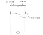
- FIG. 1 is a diagram showing an embodiment of an input device of the present invention.
- the input device 100 in this embodiment includes a display unit 110, an input unit 120, a region editing unit 130, and a region control unit 140.
- the input device 100 is a device having a touch panel function, such as a mobile phone, a mobile terminal, a tablet or notebook PC (Personal Computer), an electronic book terminal, a smartphone, a PDA (Personal Digital Assistant), a game machine, or the like. It is possible to apply to.
- the display unit 110 is a display that displays a plurality of input areas for inputting information.
- This input area is, for example, a general input key on which numbers, alphabets, and Japanese kana are displayed, and a control key for inputting instructions for calling, ending, clearing, and determining.
- the input unit 120 inputs information based on an input area that includes a contact or close position among a plurality of input areas. For example, when the finger touches the input area of the input key in which “1” is entered, “1” is input to the input device 100.
- the display unit 110 and the input unit 120 constitute a touch panel.
- the area editing unit 130 edits the arrangement of input areas.
- the area editing unit 130 edits the shape (size, style, etc.) of the input area in addition to the arrangement of the input area.
- the input unit 120 is used, and the input area is edited based on the operation (input) content to the input unit 120.
- the region control unit 140 controls the input region displayed by the display unit 110 based on the result edited by the region editing unit 130.
- the area control unit 140 controls the arrangement of the input areas displayed on the display unit 110 to the arrangement edited by the area editing unit 130.
- the area control unit 140 changes the arrangement and shape of the input area displayed by the display unit 110 to the arrangement and shape edited by the area editing unit 130. Control.
- FIG. 2 is a diagram showing a detailed internal structure of the input device 100 shown in FIG.
- the input device 100 in this embodiment includes a display unit 110, an input unit 120, a region editing unit 130, a region control unit 140, an operation determination unit 150, and a storage unit 160. ing.
- FIG. 2 shows only the components related to the present invention among the components included in the input device 100.
- the display unit 110 is the same as that shown in FIG.
- the input unit 120 is the same as that shown in FIG.
- the area editing unit 130 is the same as that shown in FIG.
- the operation determination unit 150 determines a predetermined operation.
- the operation determination unit 150 is a pressure sensor, and determines whether the user holding the input device 100 is holding the input device 100 with the left or right hand based on the detected pressure. Further, the operation determination unit 150 outputs the determined operation to the region control unit 140.
- the storage unit 160 stores the operation determined by the operation determination unit 150 and the arrangement edited by the area editing unit 130 in association with each other.
- FIG. 3 is a diagram illustrating an example of correspondence between operations stored in the storage unit 160 illustrated in FIG. 2 and the arrangement of input areas.
- “Operation” is the content of the operation determined by the operation determining unit 150.
- “Input area information” is information indicating an input area, and as shown in FIG. 3, it may be a number, a character, or the like input when this input area is selected.
- Coordinates are coordinates on the display unit 110 where the input area is displayed, and indicate the arrangement of the input area.
- the coordinates may be the coordinates of the center of the input area, or may be a predetermined position (for example, the upper right corner) of the input area.
- the area control unit 140 reads the arrangement of the input area corresponding to the operation determined by the operation determination unit 150 from the storage unit 160. Then, the area control unit 140 controls the arrangement of the input areas displayed on the display unit 110 to the arrangement read from the storage unit 160. That is, when the arrangement of the input areas read from the storage unit 160 is different from the arrangement currently displayed on the display unit 110, the area control unit 140 determines the arrangement of the input areas displayed on the display unit 110 from the storage unit 160. Change to the read layout.
- a specific control method in the area control unit 140 will be described by taking as an example a case where the association illustrated in FIG. 3 is stored in the storage unit 160.
- the operation “hold left hand”, input area information “5E” and coordinates (100, 200), input area information “1A” and coordinates (80, 180), input area information “2B” and coordinates (120, 180) are associated with each other.
- the operation “hold right hand”, input area information “5E” and coordinates (110, 200), input area information “1A” and coordinates (100, 180), input area information “2B” and coordinates (140, 180) Are associated with each other.
- the operation determination unit 150 determines that the user holding the input device 100 is holding the input device 100 with the left hand, the operation is associated with the operation “hold left hand” in the storage unit 160.
- the input area of “5E” is arranged at the coordinates (100, 200), the input area of “1A” is arranged at the coordinates (80, 180), and the input area of “2B” is read out Are arranged at coordinates (120, 180).
- the operation determination unit 150 determines that the user holding the input device 100 is holding the input device 100 with the right hand, the operation is associated with the operation “hold right hand” in the storage unit 160.
- the arrangement of the input area is read, the input area of “5E” is arranged at the coordinates (110, 200), the input area of “1A” is arranged at the coordinates (100, 180), and the input area of “2B” is Arranged at coordinates (140, 180).
- the storage unit 160 stores the operation determined by the operation determining unit 150 and the arrangement and shape edited by the area editing unit 130 in association with each other. It may be what you do.
- the area control unit 140 reads the arrangement and shape of the input area corresponding to the operation determined by the operation determination unit 150 from the storage unit 160. Then, the area control unit 140 controls the arrangement and shape of the input area displayed on the display unit 110 to the arrangement and shape read from the storage unit 160. That is, the area control unit 140 determines the arrangement and shape of the input area displayed on the display unit 110 when the arrangement and shape of the input area read from the storage unit 160 are different from the arrangement and shape currently displayed on the display unit 110. Is changed to the arrangement and shape read from the storage unit 160.
- the association stored in the storage unit 160 may be any as long as the region control unit 140 can acquire the arrangement and shape of the input region corresponding to the operation determined by the operation determination unit 150.
- FIG. 4 is a diagram showing an example of the appearance of the input device 100 shown in FIG.
- the input device 100 shown in FIG. 2 is provided with a dent as an operation determination unit 150 on each of the left and right side surfaces of the housing.
- This portion is preferably provided in a range where the index finger is applied when the input device 100 is held with one hand.
- the right operation determination unit 150 detects pressure in FIG. 4
- the left operation determination unit 150 detects pressure in FIG. 4, it is determined that the input device 100 is held by the right hand.
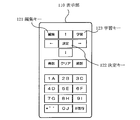
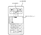
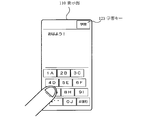
- FIG. 5 is a diagram showing an example of the arrangement of the input areas displayed on the display unit 110 shown in FIG.
- input areas such as an edit key 121, an enter key 122, a learning key 123, an arrow (direction) key, a clear key, a call key, an end key, and a numeric kana key are displayed in a predetermined arrangement. .
- FIG. 6 is a flowchart for explaining an editing process for editing the arrangement of the input areas in this embodiment.
- step 1 the input unit 120 determines whether or not the edit key 121 shown in FIG. 5 has been selected.
- the edit key 121 has been selected.
- contact or proximity to the edit key 121 it is determined that the edit key 121 has been selected. The same applies to the selection of other keys.
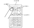
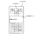
- FIG. 7 is a diagram showing a state where the edit key 121 shown in FIG. 5 is selected.
- the input unit 120 determines that the editing key 121 has been selected.
- the display unit 110 displays an edit menu in step 2.
- FIG. 8 is a diagram illustrating an example of the edit menu displayed on the display unit 110.
- an edit menu 124 for editing the input area is displayed on the display unit 110.
- the edit menu 124 includes a menu for editing the size of the input area (key size), the shape as a style, and the arrangement of the input area (key arrangement).
- step 3 When “1. key size” in the edit menu 124 shown in FIG. 8 is selected in step 3, the area editing unit 130 performs key size editing processing for editing the size of the input area in step 4. .
- the display unit 110 displays a size menu for designating the size of the input area.
- FIG. 9 is a diagram showing an example of the size menu displayed on the display unit 110.
- a size menu 125 for editing the size of the input area is displayed on the display unit 110.
- the size menu 125 is a menu in which the size (key size) of the input area can be selected from “1. Large”, “2. Medium”, “3. Small”, and “4.
- the size of the input area is determined by selecting a desired one from the four options. This process is performed for each input area (key) whose size needs to be edited.
- the size menu 125 shown in FIG. 9 is an example, and “maximum” or a numerical value indicating the size may be displayed. This size may be different depending on whether the input device 100 is held vertically or horizontally.
- the display unit 110 displays the edit menu 124 shown in FIG.
- step 5 when “2. Style (vertical / horizontal)” in the editing menu 124 shown in FIG. 8 is selected in step 5, the key style editing process for editing the style of the input area is performed in step 6.
- the unit 130 performs.
- the key style editing process is started without displaying the editing menu 124. There may be.
- the display unit 110 displays a style menu for designating the style of the input area.
- FIG. 10 is a diagram showing an example of the style menu displayed on the display unit 110.
- a style menu 126 for editing the style of the input area is displayed on the display unit 110.
- the style menu 126 is a menu in which the style (vertical and horizontal) of the input area can be selected from “1. Longitudinal”, “2. Horizontally long”, and “3. By selecting a desired one of these three options, the style of the input area is determined. This process is performed for each input area (key) whose style needs to be edited. Note that the style menu 126 shown in FIG. 10 is merely an example, and “circle”, “oval”, or the like may be displayed.
- the display unit 110 displays the editing menu 124 shown in FIG.
- the area editing unit 130 performs key layout editing processing for editing the layout of the input area in step 8.
- the key arrangement editing process is started without displaying the editing menu 124. Also good.
- the area editing unit 130 edits the arrangement of each input area.
- the display unit 110 highlights the keys one by one (for example, changes the display color, makes the key frame thick), and brings the finger into contact with or close to the position where the highlighted key is to be placed.
- the arrangement of the key may be determined.
- the area editing unit 130 performs an operation editing process for editing the operation content in step 9. .
- the display unit 110 displays an operation menu for designating an operation.
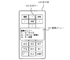
- FIG. 11 is a diagram illustrating an example of an operation menu displayed on the display unit 110.
- an operation menu 127 for editing the operation is displayed on the display unit 110.
- the operation menu 127 is a menu that allows the user to select the content of the operation determined by the operation determining unit 150 from “1. Left hand” and “2. Right hand”. By selecting a desired one of the two options, the content of the operation determined by the operation determination unit 150 is determined. Note that the operation menu 127 shown in FIG. 11 is an example, and “Left hand and right hand common” or the like may be displayed.
- the operation editing process is completed, and the region control unit 140 performs a registration process for registering the edited content in the storage unit 160 in step 10. .
- FIG. 12 is a diagram illustrating an example of a registration menu displayed on the display unit 110 in the registration process.
- a registration menu 128 that is a message for confirming whether or not to perform registration is displayed.
- this editing process may be to perform a plurality of registrations instead of one registration for each of the left hand and the right hand. Further, regardless of the operation of the left hand or the right hand, that is, a plurality of registrations may be performed by designating “common to the left hand and right hand” in editing the operation.
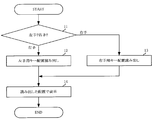
- FIG. 13 is a flowchart for explaining display processing for controlling and displaying the arrangement of the input areas in the present embodiment.
- step 11 the operation determination unit 150 determines whether the user holding the input device 100 is holding the input device 100 with the left or right hand.
- the region control unit 140 reads the left hand from the storage unit 160 in step 12. Reads the layout of the input area corresponding to the operation.
- the region control unit 140 reads the information from the storage unit 160 in step 13. Reads the arrangement of the input area corresponding to the operation of the right hand.
- step 14 the area control unit 140 changes the input area displayed on the display unit 110 to the arrangement read from the storage unit 160, and the display unit 110 displays the input area with the changed arrangement. . Needless to say, after the arrangement is changed, information is input to the input area according to the changed arrangement.
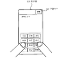
- FIG. 14 is a diagram illustrating a state where the input device 100 is held with both hands.
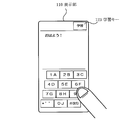
- FIG. 15 is a diagram illustrating a state where the input device 100 is held with the left hand.
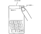
- FIG. 16 is a diagram illustrating a state where the input device 100 is held with the right hand.
- the arrangement of the input areas is controlled according to the state in which the user holds the input device 100.
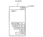
- FIG. 17 is a diagram illustrating an example of an input area arranged on the display unit 110.
- the area control unit 140 reads a plurality of registrations from the storage unit 160 and changes them to the read arrangement. .
- FIG. 18 is a diagram showing an example of the input area arranged on the display unit 110 after the learning key 123 is selected in the state where the input area is displayed in the arrangement shown in FIG.
- the area control unit 140 selects one of a plurality of registrations from the storage unit 160. Is read and changed to the read arrangement.
- the area control unit 140 sequentially reads the plurality of registrations from the storage unit 160 and changes the arrangement to the read registration. .
- the arrangement and shape of the input area as described above may be registered for each application, and the arrangement and shape of the input area may be controlled according to the activated application.
- the case where the information displayed in the input area is a number and a letter (for convenience of explanation, alphabets “A” to “J”) has been described as an example. It may contain a word kana or a plurality of alphabets. Also, numbers, kana, and alphabets (a, b, c, etc.) may be controlled to be different from each other. For example, in the above-described example, “5” and “A” are the same input area, but “5” and “A” may be controlled to different input areas. Also, control may be performed so that combinations of numbers and letters are different from each other, such as “5A” and “5E”.
- control keys such as the edit key 121, the enter key 122, and the learning key 123 may be controlled.
- the arrangement of the input keys is stored in the favorite input key arrangement corresponding to the left and right hand holding, and the input device is held with one hand.
- the input key layout according to the result of the hand identification that is held is displayed, allowing quick input and incorrect operation on either the left or right side. There is an effect that can be reduced.
- the processing performed by each component provided in the input device 100 described above may be performed by a logic circuit that is produced according to the purpose.
- a computer program (hereinafter referred to as a program) in which processing contents are described as a procedure is recorded on a recording medium readable by the input device 100, and the program recorded on the recording medium is read by the input device 100 and executed. It may be what you do.
- the recording medium readable by the input device 100 includes a transferable recording medium such as a floppy (registered trademark) disk, a magneto-optical disk, a DVD, and a CD, a storage unit 160 built in the input device 100, a ROM, It refers to a memory such as a RAM or an HDD.
- the program recorded on the recording medium is read by a CPU (not shown) provided in the input device 100, and the same processing as described above is performed under the control of the CPU.
- the CPU operates as a computer that executes a program read from a recording medium on which the program is recorded.
Landscapes
- Engineering & Computer Science (AREA)
- General Engineering & Computer Science (AREA)
- Theoretical Computer Science (AREA)
- Human Computer Interaction (AREA)
- Physics & Mathematics (AREA)
- General Physics & Mathematics (AREA)
- User Interface Of Digital Computer (AREA)
- Position Input By Displaying (AREA)
- Telephone Function (AREA)
Abstract
Description
情報を入力するための複数の入力領域を表示する表示部と、
前記複数の入力領域のうち、接触または近接された位置が含まれる入力領域に基づいた情報を入力する入力部と、
前記入力部への入力に基づいて、前記入力領域の配置を編集する領域編集部と、
前記領域編集部が編集した結果に基づいて、前記表示部が表示する前記入力領域を制御する領域制御部とを有する。
情報を入力する入力方法であって、
前記情報を入力するための複数の入力領域を表示する処理と、
前記複数の入力領域のうち、接触または近接された位置が含まれる入力領域に基づいた情報を入力する入力処理と、
前記入力処理における入力に基づいて、前記入力領域の配置を編集する処理と、
前記編集した結果に基づいて、前記表示する前記入力領域を制御する処理とを行う。
コンピュータに実行させるプログラムであって、
情報を入力するための複数の入力領域を表示する手順と、
前記複数の入力領域のうち、接触または近接された位置が含まれる入力領域に基づいた情報を入力する入力手順と、
前記入力手順における入力に基づいて、前記入力領域の配置を編集する手順と、
前記編集した結果に基づいて、前記表示する前記入力領域を制御する手順とを実行させる。
Claims (7)
- 情報を入力するための複数の入力領域を表示する表示部と、
前記複数の入力領域のうち、接触または近接された位置が含まれる入力領域に基づいた情報を入力する入力部と、
前記入力部への入力に基づいて、前記入力領域の配置を編集する領域編集部と、
前記領域編集部が編集した結果に基づいて、前記表示部が表示する前記入力領域を制御する領域制御部とを有する入力装置。 - 請求項1に記載の入力装置において、
所定の操作を判別する操作判別部と、
前記操作と、前記領域編集部が編集した前記入力領域の配置とを対応付けて記憶する記憶部とを有し、
前記領域制御部は、前記操作判別部が判別した操作に対応する前記入力領域を前記記憶部から読み出し、前記表示部が表示する前記入力領域を制御することを特徴とする入力装置。 - 請求項2に記載の入力装置において、
前記領域編集部は、前記入力領域の配置に加え、該入力領域の形状を編集することを特徴とする入力装置。 - 請求項3に記載の入力装置において、
前記記憶部は、前記操作と、前記領域編集部が編集した形状とも対応付けて記憶し、
前記領域制御部は、前記操作判別部が判別した操作に対応する前記入力領域を前記記憶部から読み出し、前記表示部が表示する前記入力領域を制御することを特徴とする入力装置。 - 請求項2乃至4のいずれか1項に記載の入力装置において、
前記操作判別部は、圧力センサーであることを特徴とする入力装置。 - 情報を入力する入力方法であって、
前記情報を入力するための複数の入力領域を表示する処理と、
前記複数の入力領域のうち、接触または近接された位置が含まれる入力領域に基づいた情報を入力する入力処理と、
前記入力処理における入力に基づいて、前記入力領域の配置を編集する処理と、
前記編集した結果に基づいて、前記表示する前記入力領域を制御する処理とを行う入力方法。 - コンピュータに、
情報を入力するための複数の入力領域を表示する手順と、
前記複数の入力領域のうち、接触または近接された位置が含まれる入力領域に基づいた情報を入力する入力手順と、
前記入力手順における入力に基づいて、前記入力領域の配置を編集する手順と、
前記編集した結果に基づいて、前記表示する前記入力領域を制御する手順とを実行させるためのプログラム。
Priority Applications (3)
| Application Number | Priority Date | Filing Date | Title |
|---|---|---|---|
| EP12782531.3A EP2708986A4 (en) | 2011-05-11 | 2012-03-06 | INPUT DEVICE |
| US14/115,214 US20140062932A1 (en) | 2011-05-11 | 2012-03-06 | Input device |
| JP2013513955A JP5880549B2 (ja) | 2011-05-11 | 2012-03-06 | 入力装置 |
Applications Claiming Priority (2)
| Application Number | Priority Date | Filing Date | Title |
|---|---|---|---|
| JP2011-106064 | 2011-05-11 | ||
| JP2011106064 | 2011-05-11 |
Publications (1)
| Publication Number | Publication Date |
|---|---|
| WO2012153565A1 true WO2012153565A1 (ja) | 2012-11-15 |
Family
ID=47139051
Family Applications (1)
| Application Number | Title | Priority Date | Filing Date |
|---|---|---|---|
| PCT/JP2012/055656 WO2012153565A1 (ja) | 2011-05-11 | 2012-03-06 | 入力装置 |
Country Status (4)
| Country | Link |
|---|---|
| US (1) | US20140062932A1 (ja) |
| EP (1) | EP2708986A4 (ja) |
| JP (1) | JP5880549B2 (ja) |
| WO (1) | WO2012153565A1 (ja) |
Families Citing this family (3)
| Publication number | Priority date | Publication date | Assignee | Title |
|---|---|---|---|---|
| CN104345944B (zh) * | 2013-08-05 | 2019-01-18 | 中兴通讯股份有限公司 | 自适应调整触摸输入面板布局的装置、方法及移动终端 |
| US9870081B2 (en) * | 2013-08-22 | 2018-01-16 | Sharp Kabushiki Kaisha | Display device and touch-operation processing method |
| CN115048007B (zh) * | 2014-12-31 | 2024-05-07 | 创新先进技术有限公司 | 调整界面操作图标分布范围的装置、方法及触摸屏设备 |
Citations (3)
| Publication number | Priority date | Publication date | Assignee | Title |
|---|---|---|---|---|
| JP2002328771A (ja) * | 2001-04-12 | 2002-11-15 | Internatl Business Mach Corp <Ibm> | タッチスクリーン・ユーザ・インターフェース |
| JP2008027183A (ja) | 2006-07-21 | 2008-02-07 | Sharp Corp | 情報処理装置 |
| JP2010182071A (ja) | 2009-02-05 | 2010-08-19 | Sharp Corp | 携帯情報端末 |
Family Cites Families (15)
| Publication number | Priority date | Publication date | Assignee | Title |
|---|---|---|---|---|
| JP4880304B2 (ja) * | 2005-12-28 | 2012-02-22 | シャープ株式会社 | 情報処理装置および表示方法 |
| US20090270078A1 (en) * | 2006-05-30 | 2009-10-29 | Gi-Seon Nam | Method for configurating keypad of terminal and the terminal and system including the terminal and the keypad capable of reconfiguration |
| JP5456230B2 (ja) * | 2006-10-30 | 2014-03-26 | 京セラ株式会社 | 携帯端末装置における操作キー群のレイアウト方法および操作キー群レイアウト装置 |
| WO2008041485A1 (en) * | 2006-09-28 | 2008-04-10 | Kyocera Corporation | Operation key layout method in mobile terminal device and mobile terminal device for realizing the method |
| KR101111566B1 (ko) * | 2008-05-23 | 2012-02-24 | 삼성전자주식회사 | 휴대 단말기의 인터페이스 전환 장치 및 방법 |
| JP2010154090A (ja) * | 2008-12-24 | 2010-07-08 | Toshiba Corp | 携帯端末 |
| US20110191516A1 (en) * | 2010-02-04 | 2011-08-04 | True Xiong | Universal touch-screen remote controller |
| JP5062279B2 (ja) * | 2010-03-29 | 2012-10-31 | パナソニック株式会社 | 情報機器および携帯情報機器 |
| JP5588931B2 (ja) * | 2011-06-29 | 2014-09-10 | 株式会社Nttドコモ | 移動情報端末、配置領域取得方法、プログラム |
| JP5999374B2 (ja) * | 2011-09-05 | 2016-09-28 | 日本電気株式会社 | 携帯端末装置、携帯端末制御方法及びプログラム |
| US20130300668A1 (en) * | 2012-01-17 | 2013-11-14 | Microsoft Corporation | Grip-Based Device Adaptations |
| KR101885655B1 (ko) * | 2012-10-29 | 2018-09-10 | 엘지전자 주식회사 | 이동 단말기 |
| KR102088909B1 (ko) * | 2013-03-15 | 2020-04-14 | 엘지전자 주식회사 | 이동 단말기 및 그의 변형 키패드 운용방법 |
| JP2015138499A (ja) * | 2014-01-24 | 2015-07-30 | 富士通株式会社 | 情報処理装置、入力制御方法及び入力制御プログラム |
| CN203930584U (zh) * | 2014-04-22 | 2014-11-05 | 何衢 | 一种移动终端 |
-
2012
- 2012-03-06 WO PCT/JP2012/055656 patent/WO2012153565A1/ja active Application Filing
- 2012-03-06 US US14/115,214 patent/US20140062932A1/en not_active Abandoned
- 2012-03-06 EP EP12782531.3A patent/EP2708986A4/en not_active Ceased
- 2012-03-06 JP JP2013513955A patent/JP5880549B2/ja active Active
Patent Citations (3)
| Publication number | Priority date | Publication date | Assignee | Title |
|---|---|---|---|---|
| JP2002328771A (ja) * | 2001-04-12 | 2002-11-15 | Internatl Business Mach Corp <Ibm> | タッチスクリーン・ユーザ・インターフェース |
| JP2008027183A (ja) | 2006-07-21 | 2008-02-07 | Sharp Corp | 情報処理装置 |
| JP2010182071A (ja) | 2009-02-05 | 2010-08-19 | Sharp Corp | 携帯情報端末 |
Non-Patent Citations (1)
| Title |
|---|
| See also references of EP2708986A4 |
Also Published As
| Publication number | Publication date |
|---|---|
| JP5880549B2 (ja) | 2016-03-09 |
| US20140062932A1 (en) | 2014-03-06 |
| EP2708986A1 (en) | 2014-03-19 |
| EP2708986A4 (en) | 2014-10-08 |
| JPWO2012153565A1 (ja) | 2014-07-31 |
Similar Documents
| Publication | Publication Date | Title |
|---|---|---|
| JP5204305B2 (ja) | 携帯用端末機におけるパターン認識を用いたユーザインターフェース装置及び方法 | |
| CN103631514B (zh) | 用于触笔功能的操作的方法及支持该方法的电子装置 | |
| US20140123049A1 (en) | Keyboard with gesture-redundant keys removed | |
| US9703418B2 (en) | Mobile terminal and display control method | |
| JP2017156966A (ja) | 情報処理装置、情報処理方法、およびプログラム | |
| JP6109788B2 (ja) | 電子機器及び電子機器の作動方法 | |
| KR20120036897A (ko) | 터치 감지형 디스플레이 상에서의 선택 | |
| JP5876747B2 (ja) | 通信端末装置、制御方法、プログラム、及び、記録媒体 | |
| JP5880549B2 (ja) | 入力装置 | |
| CN107037888A (zh) | 一种输入方法、装置和用于输入的装置 | |
| CN105892872A (zh) | 一种基于触摸屏的电子书自动滚屏控制方法及移动终端 | |
| JP2012008676A (ja) | 電子書籍表示装置 | |
| JP2013223044A (ja) | 文字入力方法及び文字入力装置 | |
| TWI288343B (en) | Touch panel keyboard of a portable device and control method thereof | |
| JP2006522555A (ja) | 縮少キーパッドを用いたアルファベット入力の装置および方法 | |
| JP2003186613A (ja) | 文字入力装置 | |
| JP5257841B2 (ja) | コマンド入力システム、その方法及びそのプログラム | |
| JP3197051U (ja) | キー入力装置 | |
| JP5245708B2 (ja) | 文字入力装置、文字入力方法及び文字入力プログラム | |
| JP5692796B2 (ja) | 情報端末、入力方法及びプログラム | |
| JP6217274B2 (ja) | 携帯端末装置及びプログラム | |
| JP2012226694A (ja) | 入力装置、入力方法およびプログラム | |
| KR101149892B1 (ko) | 휴대용 단말기, 그의 문자 입력 방법 | |
| TWI488104B (zh) | 電子裝置及控制電子裝置的方法 | |
| JP2005284585A (ja) | 文字入力検知方法 |
Legal Events
| Date | Code | Title | Description |
|---|---|---|---|
| 121 | Ep: the epo has been informed by wipo that ep was designated in this application |
Ref document number: 12782531 Country of ref document: EP Kind code of ref document: A1 |
|
| REEP | Request for entry into the european phase |
Ref document number: 2012782531 Country of ref document: EP |
|
| WWE | Wipo information: entry into national phase |
Ref document number: 2012782531 Country of ref document: EP |
|
| WWE | Wipo information: entry into national phase |
Ref document number: 14115214 Country of ref document: US |
|
| ENP | Entry into the national phase |
Ref document number: 2013513955 Country of ref document: JP Kind code of ref document: A |
|
| NENP | Non-entry into the national phase |
Ref country code: DE |