WO2012153554A1 - トルク検出装置 - Google Patents
トルク検出装置 Download PDFInfo
- Publication number
- WO2012153554A1 WO2012153554A1 PCT/JP2012/053470 JP2012053470W WO2012153554A1 WO 2012153554 A1 WO2012153554 A1 WO 2012153554A1 JP 2012053470 W JP2012053470 W JP 2012053470W WO 2012153554 A1 WO2012153554 A1 WO 2012153554A1
- Authority
- WO
- WIPO (PCT)
- Prior art keywords
- magnetic
- torque
- magnetic field
- torsion bar
- input shaft
- Prior art date
- Legal status (The legal status is an assumption and is not a legal conclusion. Google has not performed a legal analysis and makes no representation as to the accuracy of the status listed.)
- Ceased
Links
Images





Classifications
-
- B—PERFORMING OPERATIONS; TRANSPORTING
- B62—LAND VEHICLES FOR TRAVELLING OTHERWISE THAN ON RAILS
- B62D—MOTOR VEHICLES; TRAILERS
- B62D6/00—Arrangements for automatically controlling steering depending on driving conditions sensed and responded to, e.g. control circuits
- B62D6/08—Arrangements for automatically controlling steering depending on driving conditions sensed and responded to, e.g. control circuits responsive only to driver input torque
- B62D6/10—Arrangements for automatically controlling steering depending on driving conditions sensed and responded to, e.g. control circuits responsive only to driver input torque characterised by means for sensing or determining torque
-
- G—PHYSICS
- G01—MEASURING; TESTING
- G01L—MEASURING FORCE, STRESS, TORQUE, WORK, MECHANICAL POWER, MECHANICAL EFFICIENCY, OR FLUID PRESSURE
- G01L3/00—Measuring torque, work, mechanical power, or mechanical efficiency, in general
- G01L3/02—Rotary-transmission dynamometers
- G01L3/04—Rotary-transmission dynamometers wherein the torque-transmitting element comprises a torsionally-flexible shaft
- G01L3/10—Rotary-transmission dynamometers wherein the torque-transmitting element comprises a torsionally-flexible shaft involving electric or magnetic means for indicating
- G01L3/101—Rotary-transmission dynamometers wherein the torque-transmitting element comprises a torsionally-flexible shaft involving electric or magnetic means for indicating involving magnetic or electromagnetic means
- G01L3/104—Rotary-transmission dynamometers wherein the torque-transmitting element comprises a torsionally-flexible shaft involving electric or magnetic means for indicating involving magnetic or electromagnetic means involving permanent magnets
-
- G—PHYSICS
- G01—MEASURING; TESTING
- G01L—MEASURING FORCE, STRESS, TORQUE, WORK, MECHANICAL POWER, MECHANICAL EFFICIENCY, OR FLUID PRESSURE
- G01L5/00—Apparatus for, or methods of, measuring force, work, mechanical power, or torque, specially adapted for specific purposes
- G01L5/22—Apparatus for, or methods of, measuring force, work, mechanical power, or torque, specially adapted for specific purposes for measuring the force applied to control members, e.g. control members of vehicles, triggers
- G01L5/221—Apparatus for, or methods of, measuring force, work, mechanical power, or torque, specially adapted for specific purposes for measuring the force applied to control members, e.g. control members of vehicles, triggers to steering wheels, e.g. for power assisted steering
Definitions
- the present invention relates to a torque detection device that detects torque generated in a rotating body having an input shaft and an output shaft connected via a torsion bar.
- An electric power steering device is widely used as a mechanism for assisting steering of an automobile.
- the torque detection device detects torque generated in the steering shaft, and assists steering by applying an auxiliary force by an electric motor in accordance with the detected torque.
- the torque detection device 101 disclosed in Patent Document 1 includes an outer shaft 102 serving as a torsion bar and an inner shaft 103 disposed concentrically. Torque acts on one end of the shaft and the other end of the outer shaft 102 and the inner shaft 103 detects the torque.
- the inner shaft 103 is firmly fixed to the outer shaft 102 at a first connecting portion 109 on which torque acts, and second signal generating members (magnetic generating portions) 106 are respectively provided on the other ends of the outer shaft 102 and the inner shaft 103.
- a first signal generation member (magnetism generation unit) 105 are installed, and a second signal detection member (magnetic detection unit) 108 and a first signal detection member (magnetic detection unit) 107 are installed in each of the fixed positions. is set up.
- the torque detection device 201 disclosed in Patent Document 2 includes an input shaft 202 to which torque is applied and an output shaft 203 that is arranged coaxially via a torsion bar 204.
- a first detected plate (magnetic generation unit) 205 is installed eccentrically on the outer peripheral surface of the input shaft 202, and a first magnetic sensor (magnetic detection unit) 207 is installed facing the first detected plate 205. Is done.
- a second detected plate (magnetism generating unit) 206 is installed eccentrically on the outer peripheral surface of the output shaft 203, and a second magnetic sensor (magnetic detecting unit) 208 is opposed to the second detected plate 206. Installed. Then, the rotational torque applied to the input shaft 202 is detected based on the difference in output between the first magnetic sensor 207 and the second magnetic sensor 208.
- the torque detection device 101 disclosed in Patent Document 1 has a double structure including an outer shaft 102 as a torsion bar and an inner shaft 103 arranged concentrically with the outer shaft 102, and the structure is complicated. In addition, the cost is high, and the diameter in the direction orthogonal to the inner shaft 103 is large due to the double structure, so that miniaturization is difficult.
- a second signal detection member (magnetic detection portion) 108 is disposed at the center of the shaft, and the second signal detection member 108 is arranged in a direction substantially orthogonal to the inner shaft 103. Since the second signal generating member (magnet generator) 106 is concentrically disposed on the outer side, the diameter in the direction orthogonal to the inner shaft 103 is increased, and downsizing is difficult.
- a second connection portion 110 is formed on the outer periphery of the outer shaft 102, and a guide rod 111 is connected to the second connection portion 110 and installed on the outer periphery of the outer shaft 102. Then, the rotational motion is transmitted from the second connection portion 110 to the guide rod 111.
- the guide rod 111 is installed on the outer periphery of the outer shaft 102, the structure is complicated, and the diameter in the direction orthogonal to the inner shaft 103 is increased, making it difficult to reduce the size.
- a torque detection device 201 In a torque detection device 201 disclosed in Patent Document 2, an input shaft 202 and an output shaft 203 are coaxially arranged, a first detected plate (magnetism generating unit) 205 is connected to the input shaft 202, and a second is connected to the output shaft 203.
- the detected plates (magnet generators) 206 have a complicated structure that is eccentrically attached to the outer peripheral surfaces of the input shaft 202 and the output shaft 203, respectively.
- a first magnetic sensor (magnetic detection unit) 207 facing the first detected plate 205 and a second magnetic sensor (magnetic detection unit) 208 facing the second detected plate 206 are It is installed outside one detected plate 205 and second detected plate 206.
- the torque detection device 201 disclosed in Patent Document 2 has a large diameter in a direction orthogonal to the input shaft 202 and the output shaft 203, and is difficult to reduce in size and cost.
- Patent Document 1 the magnetic detection units 107 and 108 are separately installed to face the two magnetic generation units 105 and 106, respectively. Then, torque is detected from the difference in rotation angle measured by the two magnetic detectors 107 and 108.
- the magnetic detection parts 207 and 208 are installed separately facing the two magnetism generation parts 205 and 206, respectively. Then, the torque is detected from the difference between the rotation angles measured by the two magnetic detectors 207 and 208.
- Automobiles are required to have safety, energy saving, comfort, etc., and automobiles are becoming increasingly electronic. For this reason, various electronic components such as various sensors, an A / D conversion circuit that converts the output from the various sensors into a digital signal, a microcomputer that performs electronic control, and the like are mounted on the automobile electrical component.
- various electronic components such as various sensors, an A / D conversion circuit that converts the output from the various sensors into a digital signal, a microcomputer that performs electronic control, and the like are mounted on the automobile electrical component.
- the present invention has been made in view of such problems, and an object of the present invention is to provide a torque detection device that is excellent in small size and low price and detects torque with high accuracy.
- a magnetism generator is installed at each of the opposing ends of the input shaft and the output shaft
- a magnetism detector is installed in a magnetic field generated between the two magnet generators
- the torque generated in the torsion bar is detected by the magnetic detection unit detecting a change in the magnetic field.
- the magnetism generator is installed at each of the opposite ends of the input shaft and the output shaft, and the magnetism detector is installed in a magnetic field generated between the two magnet generators,
- the magnetism generator and the magnetism detector are installed in series in the axial direction. For this reason, the magnitude
- the input shaft and the output shaft are arranged via the torsion bar, a magnetism generating unit is installed at each opposing end, and the magnetism detection is performed in a magnetic field generated between the two magnetism generating units. Because it is a simple structure to install the part, it is excellent in cost reduction.
- the torsion bar is twisted by torque, and the two magnetism generating portions are rotated in a twisted state, and the magnetic field continuously changes according to the twist.
- Torque is detected by detecting the continuous change of the magnetic field by the magnetic detection unit. Since the torque is detected according to only the continuous change of the magnetic field in such a manner, it is possible to detect the torque with high accuracy.
- the input shaft, the torsion bar, and the output shaft are preferably arranged coaxially.
- the coaxial arrangement of the input shaft, the torsion bar, and the output shaft can suppress the diameter in the direction orthogonal to the coaxial and is excellent in miniaturizing the torque detection device.
- the two magnetism generating portions are composed of a plurality of magnet members arranged concentrically on each of the coaxially orthogonal surfaces of the opposing end portions of the input shaft and the output shaft.
- the two magnetism generating portions are arranged in a plane orthogonal to the coaxial axis of the end portions of the input shaft and the output shaft facing each other, the size of the diameter orthogonal to the input shaft and the output shaft is small. It is suppressed. Therefore, it is excellent in miniaturization. Further, since the two magnet members arranged concentrically are arranged to face each other, a uniform strong magnetic field is generated between them, so that the torque can be detected with high accuracy.
- the two magnetism generating portions are composed of a plurality of magnet members arranged concentrically on each of the outer peripheral surface end portions facing the input shaft and the output shaft.
- the two magnetism generators and the magnetism detector are arranged in series in the axial direction by arranging the magnetism generators at the end portions of the outer peripheral surface facing the input shaft and the output shaft. Therefore, the size of the diameter orthogonal to the input shaft and the output shaft is suppressed. Therefore, it is excellent in miniaturization. Moreover, since the two magnet members arranged concentrically are arranged to face each other, a uniform strong magnetic field is generated therebetween. Therefore, torque can be detected with high accuracy.
- the number of the two plurality of magnet members is the same, and that all the two of the plurality of magnet members have substantially the same shape.
- a symmetric magnetic field distribution can be obtained with respect to an axis connecting the centers of the arrangement of the two magnet members. Therefore, the magnetic field changes stably and continuously according to the twist of the torsion bar that is coaxial with the axis connecting the centers of the two plurality of magnet members.
- the magnetic detection unit includes two magnetic sensors, and the two magnetic sensors are arranged at an interval that is approximately half the magnetic pole length of the magnet member.
- the torsion bar When the torque is generated, the torsion bar is twisted, and the two magnetic members are rotated in a twisted state, thereby changing the direction of the magnetic field.
- the two magnetic sensors When the two magnetic sensors are arranged at an interval that is half the magnetic pole length of the magnet member in the rotation direction of the shaft, the two magnetic sensors detect the change of the magnetic field with a phase difference of 90 °. As a result, a sine wave signal and a cosine wave signal oscillating with an amplitude corresponding to the torque are obtained, and the torque can be detected by calculating the sum of squares of both signals.
- the magnetic sensor is composed of a plurality of GMR elements.
- the two opposing magnetism generating portions are arranged so that the N magnetic pole and the S magnetic pole face each other, and the direction of the magnetic field formed by the opposing N magnetic pole and the S magnetic pole is It is preferable that the sensitivity axes of the plurality of GMR elements are set so as to be in the same direction as the sensitivity axes of the plurality of GMR elements at the positions of the plurality of GMR elements.
- the torque can be detected with high sensitivity by matching the direction of the magnetic field formed between the two opposing magnetism generators and the direction of the sensitivity axes of the plurality of GMR elements.
- the plurality of GMR elements include a pinned magnetic layer whose magnetization direction is fixed, a free magnetic layer whose magnetization direction is changed by an external magnetic field, and a nonmagnetic conductive layer positioned between the pinned magnetic layer and the free magnetic layer And an element portion in which the fixed magnetization direction of the pinned magnetic layer is a sensitivity axis direction, and the element portion includes intermediate positions in the element length direction and both end portions orthogonal to the element width direction of the element portion.
- a concave portion is formed in the thickness direction, a permanent magnet layer is provided in the concave portion, an element continuous body is constituted by the element portion and the permanent magnet layer, and the sensitivity axis direction is the element width.
- the magnetization direction of the free magnetic layer is directed in the element length direction by the permanent magnet layer, and the plurality of element continuous bodies are spaced in the element width direction.
- the elements of the element connecting body adjacent to each other It is preferable that ends of the longitudinal direction forms a connection has been meandering.
- the resistance values of the plurality of GMR elements when the external magnetic field is zero, the resistance values of the plurality of GMR elements have a substantially median value, and the median value is output according to the change of the external magnetic field. An output can be obtained. Further, the torque can be detected with high sensitivity by making the element portion a meander shape formed by folding a plurality of strip-like long patterns.
- the plurality of GMR elements have a structure that shields a magnetic field orthogonal to the sensitivity axis direction.
- Two magnetic sensors, two square amplifiers that square the outputs of the magnetic sensors, and a summing amplifier that adds the outputs of the two square amplifiers are installed in a magnetic field generated between the two magnetic generators.
- the two magnetic sensors formed by the two GMR elements and the two resistance elements respectively form a bridge circuit, and when the torque is generated in the torsion bar, the magnetic field changes.
- the outputs of the two magnetic sensors are squared by the respective square amplifiers, and the torque generated in the torsion bar is detected by a value obtained by adding the outputs of the two square amplifiers by the addition amplifier.
- a cosine wave signal and a sine wave signal that vibrate with substantially the same amplitude according to the torque are output from the two magnetic sensors, and the two signals are respectively squared by the square amplifiers.
- the outputs of the two square amplifiers are added by the addition amplifier, so that the square value of the amplitude is obtained.
- the torque which arises in the said torsion bar by this square value can be calculated
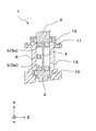
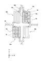
- the cross-sectional schematic of the torque detection apparatus which is 1st embodiment is shown.
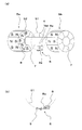
- 1 is a schematic plan view of a magnetism generator according to a first embodiment.
- the schematic explanatory drawing of the magnetism generation part and magnetic detection part which are 1st embodiment is shown.
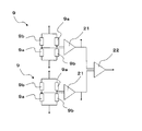
- the schematic explanatory drawing of the electric circuit of the magnetic detection part which is 1st embodiment is shown.
- An explanatory view of a torque detection device carried in an electric power steering device which is a first embodiment is shown.
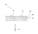
- 1 is a schematic sectional view of a GMR element according to a first embodiment. It is a plane top view of the GMR sensor which has the structure which shields the magnetic field orthogonal to the sensitivity axis which is 2nd embodiment.
- the torque detection device 1 is used by being mounted on an electric power steering device of an automobile. Torque detection device 1 detects torque generated in steering shaft 14 by steering of steering wheel 13, and a torque signal as an output thereof is transmitted to controller 17. Next, the controller 17 controls the electric motor 16 according to the torque signal and the vehicle speed, so that a steering assist force is applied to the steering shaft 14 via the reduction gear 15.
- the torque detection device 1 is used by being mounted on an electric power steering device, but is not limited to this.
- the present invention can be applied to, for example, torque detection of joint axes of various devices, in particular, finger joints of robots, or power-assisted bicycles and power tools.
- the torque detection device 1 has an input shaft 2 connected to the steering wheel 13 via the steering shaft 14 and an output shaft 3 connected to the pinion gear 18.
- the input shaft 2 and the output shaft 3 are supported by a housing 12 through a bearing 10 so as to be rotatable around the shaft, and the housing 12 is fixed to a constituent member of the automobile.
- the input shaft 2 and the output shaft 3 are arranged coaxially and are connected via a torsion bar 4 that is elastically deformed.
- the steering force of the steering wheel 13 acts on the input shaft 2 via the steering shaft 14 and acts on the output shaft 3 via the torsion bar 4.
- it acts on the wheel 20 via the pinion gear 18 and the rack gear 19, but when there is a repulsive force such as friction between the wheel 20 and the road surface, the rotation of the output shaft 3 begins to be delayed from the rotation of the input shaft 2, Torsion occurs in the torsion bar 4.
- FIG. 2 shows a schematic plan view of the magnetic generator 5 (5a, 5b) according to the first embodiment.
- the magnetic generation unit 5 includes a first magnetic generation unit 5a and a second magnetic generation unit 5b.
- 2a and 2b are schematic plan views when the first magnetic generator 5a or the second magnetic generator 5b is viewed from the torsion bar 4 side, respectively.
- the torsion bar 4 is shown in cross section.
- eight substantially arc-shaped magnet members 7 are concentrically arranged in the first magnetism generator 5a and the second magnetism generator 5b.
- FIG. 3 is a schematic explanatory diagram of the magnetic generator 5 and the magnetic detector 6 according to the first embodiment. As shown in FIG.
- both the first magnetism generating part 5a and the second magnetism generating part 5b are such that the directions of the plurality of magnet members 7 from the N pole to the S pole coincide with the longitudinal direction of the torsion bar 4.
- the magnetic poles of adjacent magnet members 7 in the same magnetism generator 5 (5a, 5b) are arranged so that the N pole and the S pole are alternately repeated.
- the magnetic detection unit 6 is composed of two GMR sensors 9.
- Patent Document 1 as shown in FIG. 10, the second signal generation member 106 is located outside the second signal detection member 108 in a direction substantially orthogonal to the inner shaft 103 with the second signal detection member 108 as the center. Are arranged concentrically.
- Patent Document 2 as shown in FIG. 11, the first magnetic sensor 207 and the second magnetic sensor 208 are connected to the first plate 205 and the second plate in a direction substantially orthogonal to the torsion bar 204. It is arranged concentrically outside the plate 206 to be detected. Therefore, in Patent Document 1 and Patent Document 2, the diameter in the direction orthogonal to the inner shaft 103 or the torsion bar 204 is large, and it is difficult to reduce the size.
- the input shaft 2, the first magnetic generator 5a, the torsion bar 4, the second magnetic generator 5b, the output shaft 3, and the two GMR sensors 9 are used.
- the two GMR sensors 9 overlap in the vicinity of the same radius as the first magnetic generator 5a and the second magnetic generator 5b in a direction substantially orthogonal to the torsion bar 4.
- the first magnetic generator 5 a, the second magnetic generator 5 b, and the two GMR sensors 9 are disposed inside the outer peripheral surfaces of the input shaft 2 and the output shaft 3, respectively. Therefore, compared to Patent Document 1 and Patent Document 2, the diameter in the direction orthogonal to the torsion bar 4 can be reduced, so that it is excellent in miniaturization.
- substantially arc-shaped magnet members 7 are concentrically arranged, but the present invention is not limited to this. Although it is possible to arrange a plurality of magnet members 7 having an arbitrary number and an arbitrary shape, torque can be detected if there are at least two magnet members 7.
- a material of the magnet member 7 a ferrite magnet, a rare earth magnet, a metal magnet, a sintered magnet, or the like can be used.
- a rubber magnet, a plastic magnet, a bond magnet, etc. can also be used.
- magnetism is generated so that N poles and S poles are alternately repeated. Part 5 can also be obtained.
- the magnetic detection unit 6 includes two GMR sensors 9. As shown in FIGS. 3 a and 3 b (enlarged views in the vicinity of the two GMR sensors 9), the two GMR sensors 9 are located at substantially the same distance from the center of the axis and are arranged on the line of the first circumference 51.
- the distance 8a on the line of the first circumference 51 that separates the equivalent points (for example, the center point, etc.) of the two GMR sensors 9 is such that the first circumference 51 is placed on the surface of the first magnetic generator 5a. It is set equal to approximately half of the magnetic pole length 8 on the line of the second circumference 52 translated in the longitudinal direction of the torsion bar 4 (X direction in FIG. 2).
- FIG. 4 is a schematic explanatory diagram of an electric circuit of the magnetic detection unit 6 according to the first embodiment.
- the two GMR sensors 9 are each formed by forming a bridge circuit with two GMR elements 9a and two resistance elements 9b.
- FIG. 6 shows a schematic cross-sectional view of the GMR element according to the first embodiment.
- the GMR element 9a includes a fixed magnetic layer 9f whose magnetization direction is fixed, a free magnetic layer 9h whose magnetization direction is changed by receiving an external magnetic field, a fixed magnetic layer 9f, and a free magnetic layer 9h. Is formed so as to include a nonmagnetic conductive layer 9g positioned therebetween, and a concave portion is provided in the free magnetic layer 9h to form a permanent magnet layer 9i.
- permanent magnet layers 9i are also formed at both ends of the free magnetic layer 9h in the length direction (Y direction in FIG. 6).
- the magnetization direction of the free magnetic layer 9h is directed to the length direction of the free magnetic layer 9h (Y direction in FIG. 6) by the permanent magnet layer 9i. Further, the pinned magnetization direction of the pinned magnetic layer 9f is directed to the element width direction (X direction in FIG. 6) orthogonal to the length direction of the free magnetic layer 9h.
- the GMR element 9a is configured as an element continuous body by an element portion having a fixed magnetic layer 9f, a nonmagnetic conductive layer 9g and a free magnetic layer 9h, and a permanent magnet layer 9i. Then, as shown in FIG. 7, a plurality of element connection bodies are arranged in parallel in the element width direction (X direction in FIG. 7), and the element length direction of the adjacent element connection bodies (in FIG. 7). The ends in the (Y direction) are connected to form a meander shape. Moreover, the permanent magnet layer 9i is provided in the middle position and both ends of the length direction (Y direction of FIG. 7) of the element continuous connection body. The sensitivity axis direction 9d is directed in the element width direction (X direction in FIG. 7).
- the magnetization direction 9k of the permanent magnet layer is magnetized in the element length direction (Y direction in FIG. 7).
- the magnetization direction of the free magnetic layer 9h is also changed by the magnetic field of the permanent magnet layer 9i. It faces the length direction (Y direction in FIG. 7).
- FIG. 7 there are three element connection bodies of the GMR element 9a, and the number of permanent magnet layers 9i provided in one element connection body is four.
- the present invention is not limited to this.
- the number can be arbitrarily set.
- the pattern shape can be arbitrarily provided according to the purpose.
- the two GMR sensors 9 are directed from the second magnetic generator 5b to the first magnetic generator 5a with the sensitivity axis direction 9d parallel to the longitudinal direction of the torsion bar 4. Is arranged. Therefore, this direction is the sensitivity axis direction 9d of the two GMR sensors 9, and the two GMR sensors 9 output a signal proportional to the value of the external magnetic field cosine in the sensitivity axis direction 9d.
- the first magnetism generating portion 5a and the second magnetism generating portion 5b are twisted. Rotate in the state. Due to the rotation in the twisted state, the opposing magnetic poles of the first magnetic generation unit 5a and the second magnetic generation unit 5b rotate in a twisted state, so the direction of the magnetic field between the magnetic poles also rotates. Therefore, the outputs of the two GMR sensors 9 are represented by signals proportional to the cosine value of the magnetic field between the rotating magnetic poles in the sensitivity axis direction 9d.
- the two GMR sensors 9 are arranged at a distance 8a on a line equal to approximately half of the magnetic pole length 8. Since approximately half of the magnetic pole length 8 corresponds to a quarter period of the magnetic pole arrangement period of the magnet member 7, the two signals output from the two GMR sensors 9 have a phase of a quarter period (90 °). ) It's off.
- the output of one GMR sensor 9 is represented by a signal proportional to the cosine value of the magnetic field between the rotating magnetic poles in the direction of the sensitivity axis, that is, the cosine wave signal, from the relationship of the trigonometric function
- the other The output of the GMR sensor 9 is proportional to the sine value of the magnetic field between the rotating magnetic poles in the sensitivity axis direction 9d, that is, can be represented by a sine wave signal.
- the first magnetism generating portion 5a and the second magnetism generating portion 5b rotate while being twisted.
- the twist causes the N and S poles of the first and second magnetic generators 5a and 5b facing each other to be obliquely displaced, so the direction of the magnetic field between the N and S poles is also oblique. become. Therefore, since the magnetic field that is inclined according to the torque rotates around the two GMR sensors 9, the outputs of the two GMR sensors 9 correspond to the cosine value in the sensitivity axis direction 9d of the inclined magnetic field. That is, it can be represented by a cosine wave signal or a sine wave signal having an amplitude corresponding to the torque.
- the first magnetism generating portion 5a and the second magnetism generating portion 5b having the same shape are arranged coaxially with different poles facing each other. Therefore, the magnetic field between the first magnetic generator 5a and the second magnetic generator 5b is symmetrically distributed on the same axis, and when there is no torque, as shown in FIG. In the vicinity of the central portion between them, there is a region in which linear magnetic lines of force parallel to the sensitivity axis direction 9d are distributed almost uniformly, and it is formed strong and stable. Further, when the first magnetism generating portion 5a and the second magnetism generating portion 5b rotate while being twisted by the torque, the magnetic field lines are inclined obliquely and change stably and continuously according to the torque.
- ⁇ A plurality of magnets are concentrically arranged, and a magnetism detection unit is arranged against the magnets.
- requiring a rotation angle from the number of the magnets which passed the said magnetic detection part by rotation is generally used.
- the detection accuracy is limited by the size of the magnet.
- the detection accuracy is excellent.
- the GMR sensor 9 is installed in a region where the linear magnetic lines of force are almost uniformly distributed, installation accuracy can be reduced and torque detection sensitivity variation can be suppressed to a small level. Therefore, the manufacturing and inspection loads are reduced, the price is reduced, and the quality is improved. In addition, when the sensitivity axis direction coincides with the direction of the linear magnetic lines of force, a strong magnetic field change can be detected, so that highly sensitive torque detection is possible.
- the magnetic detectors 107, 108, 207, and 208 are installed in the distribution of magnetic lines of force from the N pole to the S pole of the same magnet to detect the magnetic field.
- the magnetic field lines have an arc shape as shown in FIG. 8a, and the strength and direction of the magnetic field are likely to change depending on the position where the magnetic detection units 107, 108, 207, 208 are installed. Therefore, the installation accuracy of the magnetic detection units 107, 108, 207, and 208 is severe and the variation in torque detection sensitivity is large. Therefore, the cost was high and the quality was not good.
- the magnetic pole length, the length of the torsion bar 4, the diameter, the elastic modulus, and the like are set so that the torsion of the torsion bar 4 does not exceed one period of the magnetic pole arrangement with respect to the assumed maximum torque.
- the two GMR sensors 9 are mounted on a package and fixed to the housing 12. As shown in FIG. 4, the two GMR sensors 9 are each formed by forming a bridge circuit with two GMR elements 9a and two resistance elements 9b. Further, a large number of the bridge circuits are simultaneously formed on the same substrate by a semiconductor process technology. Therefore, the two GMR elements 9a constituting the bridge circuit are formed adjacent to each other with the same specifications, and thus exhibit substantially the same characteristics. The same applies to the resistance element 9b. Therefore, the two GMR sensors 9 each output a cosine wave signal and a sine wave signal that vibrate with substantially the same amplitude (A) in accordance with the torsion caused by the torque, as shown in equation (1).
- A amplitude
- the torque detection device 1 can detect the torque generated in the torsion bar 4 using this relationship. At this time, it is also possible to correct the amplitudes of the outputs of the two square amplifiers 21 to predetermined values by applying a predetermined torque. By performing such correction, the detection accuracy of the torque detection device 1 can be improved.
- the rotation angles of the first signal generation member 105 and the second signal generation member 106 are measured by the first signal detection member 107 and the second signal detection member 108, respectively.
- a relative rotation angle is calculated from the difference in rotation angle, and torque is detected according to the relative rotation angle.
- a first detected plate 205 eccentrically attached to the outer peripheral surface of the input shaft 202 and a second detected plate 206 eccentrically attached to the outer peripheral surface of the output shaft 203 are opposed to each other.
- the rotational phase difference between the input shaft 202 and the output shaft 203 is obtained from the output difference between the first magnetic sensor 207 and the second magnetic sensor 208 arranged in this manner, and torque is detected from this rotational phase difference.
- Patent Document 1 the magnetic detection units 107 and 108 are separately installed to face the two magnetic generation units 105 and 106, respectively. Then, torque is detected from the difference in rotation angle measured by the two magnetic detectors 107 and 108. Also in patent document 2, the magnetic detection parts 207 and 208 are installed separately facing the two magnetism generation parts 205 and 206, respectively. And the torque is detected from the output difference from the two magnetic detectors 207 and 208.
- the magnetism generation unit and the magnetism detection unit it is necessary to install two combinations of the magnetism generation unit and the magnetism detection unit, and two errors associated with the two installations occur in the detected torque value. Further, the magnetic field lines at the positions where the magnetic detectors are installed have an arc shape, and the two error values associated with the two installations are large.
- a package in which two GMR sensors 9 are mounted with an interval of approximately half of the magnetic pole length 8 is arranged at the center between the first magnetic generator 5a and the second magnetic generator 5b. Install in the vicinity of the part.
- the magnetic field lines in the vicinity of the central portion are linear and almost uniformly distributed. Therefore, the error associated with this package installation is very small. Therefore, only an error that mounts the two GMR sensors 9 on the package with an interval of about half of the magnetic pole length 8 remains as an effective error.
- the error associated with the installation of the magnetic detection unit with respect to the magnetic generation unit is greater than that of the torque detection devices 101 and 201 disclosed in Patent Literature 1 and Patent Literature 2 in the present embodiment. 1 is small. Therefore, according to this embodiment, it is possible to detect torque with high accuracy.
- the torque detection device 101 disclosed in Patent Document 1 has a double structure including an outer shaft 102 as a torsion bar and an inner shaft 103 that is concentrically disposed on the outer shaft 102. Because of its complicated structure, the cost was high. Further, as shown in FIG. 11, the torque detection device 201 disclosed in Patent Document 2 has a double structure in which a torsion bar 204 is inserted into an input shaft 202 and an output shaft 203, and a first detected plate. The cost is high because 205 and the second plate 206 to be detected are complex structures that are eccentrically attached to the input shaft 202 or the output shaft 203, respectively.
- the input shaft 2, the first magnetic generator 5 a, the torsion bar 4, the second magnetic generator 5 b, the output shaft 3, and the two GMR sensors 9 are used.
- the maximum value of the rotation angle is 360 °
- the structure of the detection part of the torque detection devices 101 and 201, the calculation method for calculating the torque, etc. are 360 ° which is the maximum rotation angle. It is necessary to set up to.
- the rotation angle due to the torque generated in the torsion bar 4 is about 5 °, and at most 10 ° or less.
- the torque detection devices 101 and 201 disclosed in Patent Document 1 and Patent Document 2 have poor detection accuracy.
- the torsion bar 4 is set so that the twist of the torsion bar 4 does not exceed one cycle of the arrangement of the magnetic poles due to the assumed maximum torque.
- the magnetism generator 5 is composed of eight magnet members 7, so that one cycle is 90 °. Therefore, a rotation angle of about 5 ° due to the torque generated in the torsion bar 4 is detected in an appropriate range of 90 °. Therefore, according to the present embodiment, the torque can be detected with high accuracy.
- torque is detected regardless of the rotation angle. Therefore, according to the magnitude of the torque to be detected, it is possible to appropriately set the magnetic pole length of the magnetism generator 5 and freely set the measurement range. Therefore, it is possible to detect the torque with high accuracy by appropriately responding to any torque magnitude.
- the magnetic detection unit 6 is configured using the two GMR sensors 9, but the present invention is not limited to this. It can also be configured by a sensor composed of a Hall element, an MI element (magnet impedance element), an AMR element (anisotropic magnetoresistive element), or the like.
- FIG. 7 is a schematic plan view of a GMR sensor having a structure for shielding a magnetic field orthogonal to the sensitivity axis according to the second embodiment.
- the GMR sensor according to the present embodiment includes two GMR elements 9a and two resistance elements 9b having a meander-shaped planar structure formed by folding a plurality of strip-like long patterns (stripes). A bridge circuit is formed.
- the sensitivity axis direction 9d is directed in the element width direction (X direction in FIG. 7) orthogonal to the length direction of the GMR element 9a.
- a shielding film 9c which is a strip-like long pattern, is provided on both sides in the length direction (Y direction in FIG. 7) of the GMR element 9a in a non-contact manner in the length direction (Y direction in FIG. 7).
- the shielding film 9c is made of a soft magnetic film and exhibits an effect of shielding a magnetic field component in the length direction (Y direction in FIG. 7). Therefore, only the magnetic field component in the direction orthogonal to the length direction (X direction in FIG. 7), that is, the magnetic field component parallel to the sensitivity axis direction 9d can enter the region occupied by the GMR element 9a.
- the shielding film 9c since the shielding film 9c exhibits the effect of amplifying the magnetic field component parallel to the sensitivity axis direction 9d, the sensitivity for detecting the torque is also improved.
- the difference between the first embodiment and the second embodiment is only the presence or absence of the shielding film 9c, and the others are basically the same.
- two GMR sensors 9 are installed at substantially the center of the opposing magnetic poles of the first magnetic generator 5a and the second magnetic generator 5b to detect a change in the magnetic field at this position. Torque is detected. In the vicinity of this position, as shown in FIG. 8b, when there is no torque, the magnetic lines of force (magnetic field) are distributed linearly in parallel to the sensitivity axis direction 9d, and when torque is generated, the magnetic lines of force (magnetic field) are in the direction of the sensitivity axis. It begins to change with respect to 9d and changes.
- magnetic field line substantially orthogonal to the sensitivity axis direction 9d as shown in FIG. 8a.
- This magnetic field line is not used for torque detection but acts as a noise component, but is shielded by the shielding film 9c.
- the shielding film 9c blocks the leakage magnetic field from the peripheral parts and the like, noise components due to these are also reduced.
- the soft magnetic film constituting the shielding film 9c can be formed of NiFe, CoFe, CoFeSiB, CoZrNb, or the like.
- FIG. 9 shows a schematic cross-sectional view of a torque detector according to the third embodiment.
- the magnetism generator 5 includes a plurality of magnet members 7 that are arranged concentrically at each of the opposing outer peripheral surface ends of the input shaft 2 and the output shaft 3. Become.
- the magnetism detection part 6 is installed in the magnetic field produced between the two magnetism generation parts 5.
- the input shaft 2, the magnetic generator 5 (5a), the torsion bar 4, the magnetic detector 6, the magnetic generator 5 (5b) and the output shaft 3 are arranged in series, that is, coaxially, the torsion The diameter in the direction perpendicular to the longitudinal direction of the bar 4 (X direction in FIG. 9) can be reduced.
- the second embodiment is an outer periphery where the input shaft 2 and the output shaft 3 are opposed to each other. Since the magnetism generating portion 5 is provided at the end of the surface, the torsion bar 4 can be relatively shortened. Therefore, the dimension of the longitudinal direction (X direction of FIG. 9) of the torsion bar 4 can be made small compared with 1st embodiment.
- the difference between the first embodiment and the third embodiment is only the position where the magnetism generator 5 is installed, and the others are basically the same.
Landscapes
- Physics & Mathematics (AREA)
- General Physics & Mathematics (AREA)
- Engineering & Computer Science (AREA)
- Chemical & Material Sciences (AREA)
- Combustion & Propulsion (AREA)
- Transportation (AREA)
- Mechanical Engineering (AREA)
- Electromagnetism (AREA)
- Power Steering Mechanism (AREA)
Abstract
【課題】本発明は、小型かつ低価格に優れると共に高精度にトルクを検出するトルク検出装置を提供することを目的とする。 【解決手段】力が作用する入力軸2と、弾性変形するトーションバー4と、トーションバー4を介して入力軸2に連結される出力軸3とを同軸に配置し、入力軸2と出力軸3との対向する端部のそれぞれに第一の磁気発生部5aと第二の磁気発生部5bを設置し、第一の磁気発生部5aと第二の磁気発生部5bの間に生じる磁界内に磁気検知部6を設置し、磁界の変化を磁気検知部6が検知することで、トーションバー4に生じるトルクを検出する。
Description
本発明は、トーションバーを介して連結される入力軸と出力軸とを有する回転体に生じるトルクを検出するトルク検出装置に関する。
自動車の操舵を補助する機構として電動パワーステアリング装置が普及している。この電動パワーステアリング装置は、トルク検出装置がステアリングシャフトに生じるトルクを検出し、この検出されたトルクに応じて電動モータにより補助力を加え操舵を補助している。
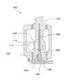
特許文献1に開示されるトルク検出装置101は、本願の図10に示すように、トーションバーとしての外軸102と同心的に配置される内軸103とを備え、外軸102と内軸103との一方の端部にトルクが作用し、外軸102と内軸103との他方の端部でトルクを検出する。
内軸103がトルクの作用する第一接続部分109で外軸102に堅固に固定され、外軸102及び内軸103の前記他方の端部にそれぞれ第二の信号発生部材(磁気発生部)106と第一の信号発生部材(磁気発生部)105が設置され、それぞれの一つの定置に第二の信号検出部材(磁気検知部)108と第一の信号検出部材(磁気検知部)107とが設置されている。
特許文献2に開示されるトルク検出装置201は、本願の図11に示すように、トルクが付与される入力軸202とトーションバー204を介して同軸に配置される出力軸203を備える。
第一の被検知板(磁気発生部)205が入力軸202の外周面に偏心的に設置され、第一の被検知板205に対向して第一の磁気センサ(磁気検知部)207が設置される。第二の被検知板(磁気発生部)206が、出力軸203の外周面に偏心的に設置され、第二の被検知板206に対向して第二の磁気センサ(磁気検知部)208が設置される。そして、第一の磁気センサ207と第二の磁気センサ208との出力の差に基づいて入力軸202に付与される回転トルクを検出する。
特許文献1に開示されるトルク検出装置101は、トーションバーとしての外軸102と外軸102に同心的に配置される内軸103とを備える二重構造であり、その構造が複雑であるためにコストが高いと共に、二重構造のために内軸103に直交する方向の径が大きくなり小型化が困難であった。
また、外軸102の他方の端部の領域において、第二の信号検出部材(磁気検知部)108が軸中心に配置され、内軸103に略直交する方向において第二の信号検出部材108の外側に第二の信号発生部材(磁気発生部)106が同心的に配置されているため、内軸103に直交する方向の径が大きくなり小型化が困難であった。
また、外軸102の外周に第二接続部分110が形成され、カイドロッド111が第二接続部分110に連結されて、外軸102の外周に設置されている。そして、回転運動が第二接続部分110からカイドロッド111に伝達される。このように、カイドロッド111が外軸102の外周に設置される構造のために、その構造が複雑であると共に、内軸103に直交する方向の径が大きくなり小型化が困難であった。
特許文献2に開示されるトルク検出装置201は、入力軸202と出力軸203とが同軸に配置され、入力軸202に第一の被検知板(磁気発生部)205及び出力軸203に第二の被検知板(磁気発生部)206が、それぞれ入力軸202及び出力軸203の外周面に偏心して取り付けられる複雑な構造である。そして、第一の被検知板205に対向して第一の磁気センサ(磁気検知部)207及び第二の被検知板206に対向して第二の磁気センサ(磁気検知部)208が、第一の被検知板205及び第二の被検知板206の外側に設置されている。
そのため、特許文献2に開示されるトルク検出装置201は、入力軸202及び出力軸203に直交する方向の径が大きくなり小型化が困難であると共に、コストが高かった。
特許文献1においては、二つの磁気発生部105、106のそれぞれに対向して磁気検知部107、108を別々に設置する。そして、二つの磁気検知部107、108が計測した回転角度の差からトルクを検出している。同じように、特許文献2においても、二つの磁気発生部205、206のそれぞれに対向して磁気検知部207、208を別々に設置する。そして、二つの磁気検知部207、208が計測した回転角度の差からトルクを検出している。
そのため、磁気発生部と磁気検知部の組み合わせを二つ設置することが必要であり、設置コストが増大すると共に、この二つの設置に伴う二つの誤差がトルクの検出値に生じることになり、検出精度が劣っていた。
また、全周360°回転角度の内の数度の角度差からトルクを検出するため、検出精度が劣っていた。
また、全周360°回転角度の内の数度の角度差からトルクを検出するため、検出精度が劣っていた。
自動車には安全性、省エネ性、快適性等が求められ、自動車の電子化が進展している。このため、自動車電装部品には、各種センサ、前記各種センサからの出力をデジタル信号に変換するA/D変換回路、また、電子制御を行うマイコン等と多数の電子部品が搭載されている。
このため、省スペース化が必須であり、前記各種センサを含めた電子部品の小型化が要求されている。また、自動車コストの数十%を電子部品が占めると言われる状況では、前記各種センサを含めた電子部品の低価格化が求められている。
本発明は、このような課題を顧みてなされたものであり、小型かつ低価格に優れると共にトルクを高精度に検出するトルク検出装置を提供することを目的とする。
力が作用する入力軸と、弾性変形するトーションバーと前記トーションバーを介して前記入力軸に連結される出力軸とを有し、前記入力軸と前記トーションバーと前記出力軸とは一体的に回転可能に設けられ、前記入力軸と前記出力軸との対向する端部のそれぞれに磁気発生部が設置され、二つの前記磁気発生部の間に生じる磁界内に磁気検知部が設置され、前記磁界の変化を前記磁気検知部が検知することで、前記トーションバーに生じるトルクを検出することを特徴とする。
前記磁気発生部が前記入力軸と前記出力軸との対向する端部のそれぞれに設置され、前記磁気検知部が二つの前記磁気発生部の間に生じる磁界内に設置されるので、二つの前記磁気発生部と磁気検知部とは軸方向に直列に設置される。このため、前記入力軸と前記出力軸とに直交する径の大きさが抑制され、小型化に優れる。
また、前記入力軸と前記出力軸とが前記トーションバーを介して配置され、それぞれの対向する端部に磁気発生部を設置し、二つの前記磁気発生部の間に生じる磁界内に前記磁気検知部を設置する単純な構造であるので、低価格化に優れる。
また、トルクによって前記トーションバーが捩れ、二つの前記磁気発生部が捩れた状態で回転し、前記捩れに応じて磁界は連続的に変化する。この磁界の連続的な変化を前記磁気検知部が検知することで、トルクが検出される。このような態様で磁界の連続的な変化のみに応じてトルクを検出するため、高精度にトルクを検出することが可能である。
よって、本発明によれば、小型かつ低価格に優れると共に高精度にトルクを検出するトルク検出装置を提供することができる。
前記入力軸、前記トーションバー及び前記出力軸が、同軸に配置されることが好ましい。
前記入力軸、前記トーションバー及び前記出力軸が同軸に配置されることは、前記同軸に直交する方向の径を抑制できるので、トルク検出装置の小型化に優れる。
二つの前記磁気発生部が前記入力軸と前記出力軸との対向する端部の前記同軸に直交する面のそれぞれに同心状に配列される複数の磁石部材からなることが好ましい。
二つの前記磁気発生部が前記入力軸と前記出力軸との対向する端部の前記同軸に直交する面内に配置されるので、前記入力軸と前記出力軸とに直交する径の大きさが抑制される。よって、小型化に優れる。また、同心状に配列される二つの前記複数の磁石部材が対向して配置されるので、その間に均一な強い磁界が生まれる、よって、高精度にトルクを検出することができる。
二つの前記磁気発生部が前記入力軸と前記出力軸との対向する外周面端部のそれぞれに同心状に配列される複数の磁石部材からなることが好ましい。
二つの前記磁気発生部が前記入力軸と前記出力軸との対向する外周面端部に配置されることで、二つの前記磁気発生部と前記磁気検知部とが軸方向に直列に配置されるので、前記入力軸と前記出力軸とに直交する径の大きさが抑制される。よって、小型化に優れる。また、同心状に配列される二つの前記複数の磁石部材が対向して配置されるので、その間に均一な強い磁界が生まれる。よって、高精度にトルクを検出することができる。
二つの前記複数の磁石部材が同数であり、且つ二つの前記複数の磁石部材の全てが略同形状であることが好ましい。
このような態様であれば、二つの前記複数の磁石部材の配列の中心を結んだ軸に対し、対称的な磁場分布を得ることができる。よって、二つの前記複数の磁石部材の配列の中心を結んだ軸と同軸である前記トーションバーの捩れに応じて、磁界は安定的に連続的な変化をする。
前記磁気検知部が二つの磁気センサからなり、前記二つの磁気センサが前記磁石部材の磁極長の略半分である間隔に配置されることが好ましい。
トルクが生じることで前記トーションバーが捩れ、二つの前記複数の磁石部材が互いに捩れた状態で回転することで磁界の方向が変化する。二つの前記磁気センサが軸の回転方向に前記磁石部材の磁極長の半分である間隔に配置されると、二つの前記磁気センサは前記磁界の変化を互いに90°の位相差で検知する。その結果、トルクに応じる振幅で振動する正弦波信号と余弦波信号とが得られ、両信号の二乗和を算出することでトルクを検出することができる。
前記磁気センサが複数のGMR素子からなることが好ましい。
このような態様であれば、トルクを高感度に検出することが可能である。
トルクがゼロの際に、対向する二つの前記磁気発生部が互いにN磁極とS磁極とを対向するように配置され、対向する前記N磁極と前記S磁極とが形成する磁界の方向が、前記複数のGMR素子の位置で前記複数のGMR素子の感度軸と同じ方向になるように、前記複数のGMR素子の感度軸が設定されていることが好ましい。
対向する二つの前記磁気発生部の間に形成される磁界の方向と前記複数のGMR素子の感度軸の方向とを一致させることで、トルクを高感度に検出することが可能となる。
前記複数のGMR素子が、磁化方向が固定される固定磁性層と、外部磁界によって磁化方向が変動する自由磁性層と、前記固定磁性層と前記自由磁性層との間に位置する非磁性導電層とを有し、前記固定磁性層の固定磁化方向が感度軸方向である素子部を備え、前記素子部には、前記素子部の素子幅方向に直交する素子長さ方向の途中位置及び両端部に、膜厚方向に向けて凹部が形成され、この凹部内に永久磁石層が設けられ、前記素子部と前記永久磁石層とで素子連設体が構成され、前記感度軸方向が前記素子幅方向であり、外部磁界がゼロの際に前記永久磁石層によって前記自由磁性層の磁化方向が前記素子長さ方向に向けられ、前記複数の前記素子連設体が前記素子幅方向に間隔を空けて並設され、隣接する前記素子連設体の前記素子長さ方向の端部同士が接続されてミアンダ状を成していることが好ましい。
このような態様であれば、外部磁界がゼロの際に前記複数のGMR素子の抵抗値が略中央値となり、外部磁界の変化に応じ前記中央値を中心に出力されるので、線形性の良い出力を得ることが可能となる。また、前記素子部を複数の帯状の長尺パターンが折り返してなるミアンダ形状にすることで、トルクを高感度に検出することが可能となる。
前記複数のGMR素子が、前記感度軸方向に直交する磁界を遮蔽する構造を有することが好ましい。
前記入力軸と前記出力軸との対向する面にそれぞれ配列される前記複数の磁石部材の近傍には、磁極間に円弧状の形状をした前記感度軸方向に略直交する磁力線が分布している。この磁力線はトルク検出に用いられず、この磁力線はノイズとして働く。よって、前記感度軸方向に直交する磁界を遮蔽する構造を有することは、S/N比の大きい出力が得られると共に、前記入力軸と前記出力軸との間隔を短くできるので小型化に優れる。
二つの前記磁気センサと前記磁気センサの出力を二乗する二つの二乗アンプと二つの前記二乗アンプの出力を加算する加算アンプとを有し、二つの前記磁気発生部の間に生じる磁界内に設置される二つの前記磁気センサがそれぞれに二つの前記GMR素子と二つの抵抗素子とでブリッジ回路を形成してなり、前記トーションバーにトルクが生じると前記磁界が変化し、この前記磁界の変化による二つの前記磁気センサの出力がそれぞれに各前記二乗アンプによって二乗され、二つの前記二乗アンプの出力が前記加算アンプにより加算された値によって、前記トーションバーに生じるトルクを検出することが好ましい。
このような態様であれば、トルクに応じてほぼ同じ振幅で振動する余弦波信号と正弦波信号とが二つの前記磁気センサから出力され、この二つの信号がそれぞれに各前記二乗アンプによって二乗され、二つの前記二乗アンプの出力が前記加算アンプにより加算されることで、前記振幅の二乗値が得られる。そして、この二乗値によって前記トーションバーに生じるトルクを求めることができる。
本発明によれば、小型かつ低価格に優れると共に高精度にトルクを検出するトルク検出装置を提供することができる。
<第一の実施形態>
第一の実施形態について、図1から図6の図面に基づいて説明する。図5に示すように、トルク検出装置1は、自動車の電動パワーステアリング装置に搭載されて用いられる。ステアリングホイール13の操舵によりステアリングシャフト14に生じるトルクをトルク検出装置1が検出し、その出力であるトルク信号が制御器17に送信される。次に、制御器17が、前記トルク信号と車速とに応じて電動モータ16を制御することで、減速ギア15を介してステアリングシャフト14に操舵補助力が加えられる。
第一の実施形態について、図1から図6の図面に基づいて説明する。図5に示すように、トルク検出装置1は、自動車の電動パワーステアリング装置に搭載されて用いられる。ステアリングホイール13の操舵によりステアリングシャフト14に生じるトルクをトルク検出装置1が検出し、その出力であるトルク信号が制御器17に送信される。次に、制御器17が、前記トルク信号と車速とに応じて電動モータ16を制御することで、減速ギア15を介してステアリングシャフト14に操舵補助力が加えられる。
本実施形態では、トルク検出装置1は電動パワーステアリング装置に搭載されて用いられるが、これに限定されるものではない。本発明は、例えば、各種機器の関節軸、特に、ロボットの指関節、または、電動アシスト自転車及び電動工具類等のトルク検知に応用することができる。
トルク検出装置1は、ステアリングシャフト14を介してステアリングホイール13に接続される入力軸2と、ピニオンギア18に接続される出力軸3を有する。入力軸2と出力軸3とは、ベアリング10を介して軸周りに回転自在に筐体12に支持され、筐体12は自動車の構成部材に固定されている。
入力軸2と出力軸3とは、同軸に配置され、弾性変形するトーションバー4を介して連結されている。ステアリングホイール13の操舵力はステアリングシャフト14を介して入力軸2に作用し、トーションバー4を介して出力軸3に作用する。そして、ピニオンギア18、ラックギア19を介して車輪20に作用するが、車輪20と路面との摩擦等の反発力がある際には、出力軸3の回転が入力軸2の回転に遅れ始め、トーションバー4に捩れが発生する。
図2に第一の実施形態である磁気発生部5(5a、5b)の平面略図を示す。本実施形態では、磁気発生部5は、第一の磁気発生部5aと第二の磁気発生部5bとによって構成される。この図2aと図2bは、それぞれ、トーションバー4側から第一の磁気発生部5aまたは第二の磁気発生部5bを見た際の平面略図である。ただし、トーションバー4は断面で図示している。図2に示すように、第一の磁気発生部5aと第二の磁気発生部5bとは、八個の略円弧状の磁石部材7が同心的に配列されている。図3に第一の実施形態である磁気発生部5と磁気検知部6の概略説明図を示す。図3aに示すように、第一の磁気発生部5aと第二の磁気発生部5bとは共に、複数の磁石部材7のN極からS極への向きがトーションバー4の長手方向に一致し、同一の磁気発生部5(5a、5b)内の隣接する磁石部材7の磁極が交互にN極とS極とが繰り返すように配列されている。また、磁気検知部6は、二つのGMRセンサ9によって構成されている。
特許文献1では、図10に示すように、第二の信号検出部材108を中心にして、内軸103に略直交する方向において第二の信号検出部材108の外側に第二の信号発生部材106が同心的に配置されている。また、特許文献2では、図11に示すように、第一の磁気センサ207と第二の磁気センサ208とが、トーションバー204に略直交する方向において第一の被検知板205と第二の被検知板206との外側に同心的に配置されている。よって、特許文献1と特許文献2とは、内軸103またはトーションバー204に直交する方向の径が大きくなり小型化が困難であった。
ところが、本実施形態は、図2、図3に示すように、入力軸2、第一の磁気発生部5a、トーションバー4、第二の磁気発生部5b、出力軸3及び二つのGMRセンサ9は、軸方向(図2のX方向)に配置されている。そして、二つのGMRセンサ9は、トーションバー4に略直交する方向において、第一の磁気発生部5a及び第二の磁気発生部5bと同一半径近傍に重なり合っている。また、第一の磁気発生部5a、第二の磁気発生部5b及び二つのGMRセンサ9が、それぞれ入力軸2及び出力軸3の外周面より内側に配置されている。よって、特許文献1及び特許文献2に比べて、トーションバー4に直交する方向の径を小さくできるので小型化に優れる。
本実施形態では、八個の略円弧状の磁石部材7を同心的に配列したが、これに限定されるものではない。任意の個数で、且つ任意の形状である複数の磁石部材7を配列することが可能であるが、最低二個の磁石部材7があればトルクを検出することができる。磁石部材7の材料として、フェライト磁石、希土類磁石、金属磁石及び焼結磁石等を用いることができる。また、ゴム磁石、プラスチック磁石、ボンド磁石等を用いることもできる。また、磁石部材7を複数設けずに、一つの磁石部材を軸方向(図2のX方向)に交互に着磁することによって、交互にN極とS極とを繰り返すように配列する磁気発生部5を得ることもできる。
本実施形態では、磁気検知部6は二個のGMRセンサ9によって構成される。図3a及び図3b(二つのGMRセンサ9近傍の拡大図)に示すように、二つのGMRセンサ9が軸中心から略同距離にあり第一の円周51の線上に配置されている。そして、二つのGMRセンサ9の同等な点(例えば、中心点等)を隔てる第一の円周51の線上の距離8aは、第一の円周51を第一の磁気発生部5aの表面にトーションバー4の長手方向(図2のX方向)に平行移動した第二の円周52の線上での磁極長の略半分8に等しく設定されている。
図4に第一の実施形態である磁気検知部6の電気回路の概略説明図を示す。図4に示すように、二つのGMRセンサ9は、それぞれ二つのGMR素子9aと二つの抵抗素子9bとでブリッジ回路を形成してなる。
図6に第一の実施形態であるGMR素子の断面略図を示す。GMR素子9aは、図6に示すように、磁化方向が固定される固定磁性層9fと、外部磁界を受けて磁化方向が変動する自由磁性層9hと、固定磁性層9fと自由磁性層9hとの間に位置する非磁性導電層9gを含むように形成され、自由磁性層9hに凹部が設けられて永久磁石層9iが形成されている。また、図示していないが、自由磁性層9hの長さ方向(図6のY方向)の両端部にも永久磁石層9iが形成されている。そして、外部磁界がゼロの際に永久磁石層9iによって自由磁性層9hの磁化方向は自由磁性層9hの長さ方向(図6のY方向)に向けられている。また、固定磁性層9fの固定磁化方向は自由磁性層9hの長さ方向に直交する素子幅方向(図6のX方向)に向けられている。
また、GMR素子9aは、固定磁性層9f、非磁性導電層9g及び自由磁性層9hを有する素子部と永久磁石層9iとで素子連設体に構成される。そして、図7に示すように、複数の素子連設体が素子幅方向(図7のX方向)に間隔を空けて並設され、隣接する素子連設体の素子長さ方向(図7のY方向)の端部同士が接続されてミアンダ状を成している。また、永久磁石層9iが、素子連設体の長さ方向(図7のY方向)の途中位置と両端部とに設けられている。そして、感度軸方向9dは素子幅方向(図7のX方向)に向けられている。永久磁石層の磁化方向9kは素子長さ方向(図7のY方向)に着磁されており、外部磁界がゼロの際には永久磁石層9iの磁界によって自由磁性層9hの磁化方向も素子長さ方向(図7のY方向)に向いている。
図7では、GMR素子9aの素子連設体は3本であり、1本の素子連設体に設けられた永久磁石層9iの数は4個であるが、これに限定されるものではなく、前記の数は任意に設けることができる。また、パターン形状も目的に応じて任意に設けることが可能である。
そして、二つのGMRセンサ9は、図3に示すように、感度軸方向9dがトーションバー4の長手方向に平行にして第二の磁気発生部5bから第一の磁気発生部5aに向けられるように配置されている。よって、この方向が二つのGMRセンサ9の感度軸方向9dであり、二つのGMRセンサ9は、外部磁界が感度軸方向9dへ余弦された値に比例する信号を出力する。
入力軸2に作用する操舵力と出力軸3に作用する反発力とにより生じるトルクに応じてトーションバー4が捩れると、第一の磁気発生部5aと第二の磁気発生部5bとが捩れた状態で回転する。この捩れた状態での回転によって、第一の磁気発生部5aと第二の磁気発生部5bとの対向する磁極が捩れた状態で回転するので、この磁極間の磁界の方向も回転する。よって、二つのGMRセンサ9の出力は、この回転する磁極間の磁界の感度軸方向9dへの余弦された値に比例する信号で表わされる。
この際、二つのGMRセンサ9は、磁極長の略半分8に等しい線上の距離8aを隔てて配置されている。この磁極長の略半分8は、磁石部材7の磁極配列周期の1/4周期に相当するので、二つのGMRセンサ9から出力される二つの信号は、互いに位相が1/4周期(90°)ずれている。よって、一方のGMRセンサ9の出力を、回転する磁極間の磁界の感度軸方向への余弦された値に比例する信号、即ち、余弦波信号で表わす際は、三角関数の関係から、他方のGMRセンサ9の出力は、回転する磁極間の磁界の感度軸方向9dへの正弦された値に比例する、即ち、正弦波信号で表わせる。
トルクに応じてトーションバー4が捩れると、第一の磁気発生部5aと第二の磁気発生部5bとが捩れた状態で回転する。この捩れによって、第一の磁気発生部5aと第二の磁気発生部5bとの対向するN極とS極とが斜めにずれるので、このN極とS極との間の磁界の方向も斜めになる。よって、トルクに応じて斜めになった磁界が、二つのGMRセンサ9の回りを回転するので、二つのGMRセンサ9の出力は、斜めになった磁界の感度軸方向9dへの余弦値に応じた、即ち、トルクに応じた振幅を持つ余弦波信号または正弦波信号で表わせる。
本実施形態では、同じ形状をした第一の磁気発生部5aと第二の磁気発生部5bとを、異なる極を対向させて同軸に配置している。そのため、第一の磁気発生部5aと第二の磁気発生部5bとの間の磁界は、前記同軸に対称的に分布し、図8bに示すように、トルクが無い際には、対向する磁極間の中央部近傍に感度軸方向9dに平行な直線状の磁力線がほぼ均一に分布している領域を持ち、強く且つ安定的に形成される。また、トルクによって第一の磁気発生部5aと第二の磁気発生部5bとが捩れた状態で回転すると、磁力線は斜めに傾斜しトルクに応じて安定的に連続的な変化をする。
本実施形態では、安定的に連続的な変化をする磁界によってトルクを検出するので、高精度なトルク検出が可能となる。
複数の磁石を同心的に配列し、前記磁石に対抗して磁気検知部を配置する。そして、回転により前記磁気検知部を通過した磁石の数から回転角度を求める方法が、一般的に用いられている。この方法で計測した回転角度からトルクを検出すると、磁石の大きさによって検出精度が制限される。ところが、本実施形態では、連続的に変化する磁界からトルクを検出するので、検出精度に優れる。
また、直線状の磁力線がほぼ均一に分布している領域にGMRセンサ9を設置すれば、設置精度が軽減されると共にトルク検出感度ばらつきを小さく抑えることができる。よって、製造及び検査の負荷が軽減され低価格となると共に品質も向上する。また、この直線状の磁力線の方向に感度軸方向を一致させると、強い磁界の変化を検知することができるので、高感度なトルク検出が可能となる。
ところが、特許文献1及び特許文献2においては、同一の磁石のN極からS極に向かう磁力線の分布中に磁気検知部107、108、207、208を設置して磁界を検知している。この磁力線は、図8aに示すように円弧状の形状をしており、磁気検知部107、108、207、208を設置する位置により磁界の強さ及び方向が変化し易い。よって、磁気検知部107、108、207、208の設置精度が厳しいと共にトルク検出感度ばらつきが大きかった。よって、コストが高いと共に品質も良くなかった。
本実施形態において、トーションバー4が大きく捩れて、磁極の配置の一周期を超えて捩れた状態で回転すると、一周期前の捩れた状態と磁極の状態が同じになるため、磁極間の距離は元に戻ったと誤認する。これにより正確なトルク検出ができなくなる。よって、想定される最大トルクに対してトーションバー4の捩れが磁極の配列の一周期を超えないように、磁極長、トーションバー4の長さ、径及び弾性率等を設定している。
二つのGMRセンサ9は、パッケージに実装されて筐体12に固定されている。図4に示すように、二つのGMRセンサ9は、それぞれ二つのGMR素子9aと二つの抵抗素子9bとでブリッジ回路を形成してなる。また、前記ブリッジ回路は、半導体プロセス技術によって、同時に同一の基板上に多数に形成される。よって、ブリッジ回路を構成する二つのGMR素子9aは、同じ仕様で隣接して形成されるので、ほぼ同じ特性を示す。このことは、抵抗素子9bにおいても同じである。よって、二つのGMRセンサ9は、(1)式に示すように、それぞれにトルクによって生じる捩れに応じてほぼ同じ振幅(A)で振動する余弦波信号と正弦波信号とを出力する。この二つの信号は、それぞれ二乗アンプ21で二乗されて、加算アンプ22で加算される。正弦波信号の二乗と余弦波信号の二乗との和は1である。よって、加算アンプ22からは、トルクに応じる振幅(A)の二乗の値が出力される。ただし、θは回転角度である。

よって、あらかじめトルクの値とトルクに応じる振幅の二乗の値の関係を求めて置けば、トルク検出装置1は、この関係を使ってトーションバー4に生じるトルクを検出することが可能となる。この際に、所定のトルクを加えて、二つの二乗アンプ21の出力の振幅がそれぞれ所定の値になるように補正することも可能である。このような補正をすることで、トルク検出装置1の検出精度を向上させることができる。
特許文献1では、第一の信号発生部材105と第二の信号発生部材106とのそれぞれの回転角度を、第一の信号検出部材107と第二の信号検出部材108とで計測し、それぞれの回転角度の差から相対的な回転角度を算出し、この相対的な回転角度に応じてトルクを検出している。
特許文献2では、入力軸202の外周面に偏心して取り付けられた第一の被検知板205と出力軸203の外周面に偏心して取り付けられた第二の被検知板206を、それぞれに対向して配置された第一の磁気センサ207と第二の磁気センサ208との出力差によって、入力軸202と出力軸203との回転位相差が求められ、この回転位相差からトルクが検出される。
特許文献1においては、二つの磁気発生部105、106のそれぞれに対向して磁気検知部107、108を別々に設置する。そして、二つの磁気検知部107、108が計測した回転角度の差からトルクを検出している。特許文献2においても、二つの磁気発生部205、206のそれぞれに対向して磁気検知部207、208を別々に設置する。そして、二つの磁気検知部207、208からの出力差からトルクを検出している。
そのため、磁気発生部と磁気検知部の組み合わせを二つ設置することが必要であり、この二つの設置に伴う二つの誤差がトルクの検出値に生じることになる。また、磁気検知部を設置する位置の磁力線は円弧状の形状をしており、この二つの設置に伴う二つの誤差の値は大きい。
ところが、本実施形態では、二つのGMRセンサ9が磁極長の略半分8の間隔を隔てて実装されたパッケージを、第一の磁気発生部5aと第二の磁気発生部5bとの間の中央部近傍に設置する。この中央部近傍の磁力線は、直線状でほぼ均一に分布している。そのため、このパッケージ設置に伴う誤差は非常に小さい。よって、二つのGMRセンサ9を磁極長の略半分8の間隔に隔ててパッケージに実装する誤差のみが、有効な誤差として残る。
このように、磁気発生部に対して磁気検知部を設置することに伴う誤差は、特許文献1及び特許文献2に開示されたトルク検出装置101、201に比べて、本実施形態のトルク検出装置1は小さい。よって、本実施形態によれば、高精度にトルクを検出することが可能である。
特許文献1に開示される、二つの磁気検知部107、108が計測した回転角度の差からトルクを検出する方式では、一般的にtan-1θの計算が行われる。例えば、(2)式によって回転角度の差(θ)を計算することが必要である。ここで、sinθとcosθとは、トルク検出装置の検出信号である。よって、回転角度を計算することなくトルクを検出する本実施形態に比べて、特許文献1に開示される方式は複雑な電子回路が必要となる。

特許文献2に開示される回転位相差からトルクを検出する方式では、操舵角度(軸の回転角度)がある程度に大きくなければ、出力である回転位相差を検出することができない。よって、検出できるトルクの大きさが制限される。
特許文献1に開示されるトルク検出装置101は、図10に示すように、トーションバーとしての外軸102と、外軸102に同心的に配置される内軸103とから構成される二重構造のために、その構造が複雑であるためにコストが高かった。また、特許文献2に開示されるトルク検出装置201は、図11に示すように、トーションバー204が入力軸202及び出力軸203の内部に挿入された二重構造、且つ第一の被検知板205と第二の被検知板206とが、それぞれ入力軸202または出力軸203に偏心して取り付けられる複雑な構造であるためにコストが高かった。
ところが、本実施形態は、図1、図3に示すように、入力軸2、第一の磁気発生部5a、トーションバー4、第二の磁気発生部5b、出力軸3及び二つのGMRセンサ9が軸方向(図1のX方向)に配置されている単純な構造であるので、特許文献1及び特許文献2に比べて価格を低く抑えることができる。
特許文献1及び特許文献2に開示されるトルク検出装置101、201では、それぞれ内軸103と外軸102との回転角度を計測し、または入力軸202と出力軸203との回転位相差が計測され、それぞれにトルクを検出している。
このような検出方法では、回転角度の最大値が360゜であることから、トルク検出装置101、201の検知部分の構造やトルクを算出する演算方法等を、最大値の回転角度である360゜まで設定することが必要である。
ところが、トーションバー4に生じるトルクによる回転角度は、5゜程度であり、大きくても10゜以下である。このような小さな回転角度を360゜の広いレンジで検出するために、特許文献1及び特許文献2に開示されるトルク検出装置101、201は、検出精度が劣っていた。
ところが、本実施形態では、想定される最大トルクによってトーションバー4の捩れが磁極の配列の一周期を超えないように設定している。そして、本実施形態では、図2に示すように、磁気発生部5を八個の磁石部材7で構成しているので、一周期は90゜である。よって、トーションバー4に生じるトルクによる5゜程度の回転角度を、90゜である適切なレンジで検出している。よって、本実施形態によれば、トルクを高精度に検出することができる。
また、本実施形態では、回転角度によらずにトルクを検出する。よって、検出するトルクの大きさに応じて、磁気発生部5の磁極長を適切に設定し、自由に測定のレンジを設定することが可能である。よって、どのようなトルクの大きさに対しても適切に対応して、トルクを高精度に検出することが可能である。
本実施形態では、磁気検知部6を二つのGMRセンサ9を用いて構成したが、これに限定されるものではない。ホール素子、MI素子(マグネトインピーダンス素子)、AMR素子(異方性磁気抵抗効果素子)等からなるセンサによっても構成可能である。
<第二の実施形態>
図7に第二の実施形態である感度軸に直交する磁界を遮蔽する構造を有するGMRセンサの平面略図を示す。図7に示すように、本実施形態であるGMRセンサは、複数の帯状の長尺パターン(ストライプ)が折り返してなるミアンダ形状の平面構造を有する、二つのGMR素子9a及び二つの抵抗素子9bによってブリッジ回路を形成してなる。そして、感度軸方向9dがGMR素子9aの長さ方向に直交する素子部幅方向(図7のX方向)に向けられている。
図7に第二の実施形態である感度軸に直交する磁界を遮蔽する構造を有するGMRセンサの平面略図を示す。図7に示すように、本実施形態であるGMRセンサは、複数の帯状の長尺パターン(ストライプ)が折り返してなるミアンダ形状の平面構造を有する、二つのGMR素子9a及び二つの抵抗素子9bによってブリッジ回路を形成してなる。そして、感度軸方向9dがGMR素子9aの長さ方向に直交する素子部幅方向(図7のX方向)に向けられている。
GMR素子9aの長さ方向(図7のY方向)の両側に、非接触に長さ方向(図7のY方向)に帯状の長尺パターンである遮蔽膜9cが設けられている。この遮蔽膜9cは、軟磁性膜からなり、長さ方向(図7のY方向)の磁界成分を遮蔽する効果を発揮する。よって、長さ方向に直交する方向(図7のX方向)の磁界成分、即ち感度軸方向9dに平行な磁界成分のみが、GMR素子9aが占める領域に進入することができる。また、遮蔽膜9cは、感度軸方向9dに平行な磁界成分を増幅する効果を発揮するので、トルクを検出する感度も向上する。
第一の実施形態と第二の実施形態との違いは、この遮蔽膜9cの有無のみであり、その他は基本的に同じである。
本実施形態では、第一の磁気発生部5aと第二の磁気発生部5bとの対抗する磁極のほぼ中央に二つのGMRセンサ9を設置して、この位置での磁界の変化を検知してトルクを検出する。この位置の近傍には、図8bに示すように、トルクの無い際に磁力線(磁界)が感度軸方向9dに対し平行に直線状に分布し、トルクが生じると磁力線(磁界)は感度軸方向9dに対して傾斜を始め変化する。また、第一の磁気発生部5aや第二の磁気発生部5bの近傍には、図8aに示すような感度軸方向9dに略直交する磁力線(磁界)がある。この磁力線(磁界)は、トルクが生じると感度軸方向9dに略直交するままに、その方向が変化する。この磁力線(磁界)はトルク検出には用いられなくノイズ成分として働くが、遮蔽膜9cによって遮蔽される。
また、遮蔽膜9cは周辺部品等からの漏洩磁場も遮断するので、これらに起因するノイズ成分も低減される。
よって、本実施形態によれば、ノイズ成分の磁界を遮蔽し、感度軸方向9dの磁界成分を増幅するので、S/N比が良好な出力を得ることができる。
また、第一の磁気発生部5aや第二の磁気発生部5bの近傍の感度軸方向9dに略直交する磁界が遮蔽されているので、第一の磁気発生部5aと第二の磁気発生部5bとの間隔を短くしても、S/N比が劣化することが低減される。よって、本実施形態によれば、この方向(図1のX方向)の小型化に優れる。
遮蔽膜9cを構成する軟磁性膜は、NiFe、CoFe、CoFeSiBやCoZrNb等で形成することができる。
<第三の実施形態>
図9に第三の実施形態であるトルク検出装置の断面略図を示す。第三の実施形態では、図9に示すように、磁気発生部5が、入力軸2と出力軸3との対向する外周面端部のそれぞれに同心状に配列される複数の磁石部材7からなる。そして、二つの磁気発生部5の間に生じる磁界内に磁気検知部6が設置される。このように、入力軸2、磁気発生部5(5a)、トーションバー4、磁気検知部6、磁気発生部5(5b)及び出力軸3が、直列、即ち同軸状に配置されるので、トーションバー4の長手方向(図9のX方向)に直交する方向の径を小さくできる。
図9に第三の実施形態であるトルク検出装置の断面略図を示す。第三の実施形態では、図9に示すように、磁気発生部5が、入力軸2と出力軸3との対向する外周面端部のそれぞれに同心状に配列される複数の磁石部材7からなる。そして、二つの磁気発生部5の間に生じる磁界内に磁気検知部6が設置される。このように、入力軸2、磁気発生部5(5a)、トーションバー4、磁気検知部6、磁気発生部5(5b)及び出力軸3が、直列、即ち同軸状に配置されるので、トーションバー4の長手方向(図9のX方向)に直交する方向の径を小さくできる。
また、入力軸2と出力軸3と対向する面のそれぞれに磁気発生部5を設ける第一の実施形態に対して、第二の実施形態は、入力軸2と出力軸3との対向する外周面端部に磁気発生部5を設けるので、相対的にトーションバー4を短くできる。よって、第一の実施形態に比べ、トーションバー4の長手方向(図9のX方向)の寸法を小さくできる。
第一の実施形態と第三の実施形態の違いは、磁気発生部5が設置された位置のみであり、その他は基本的に同じである。
1、101、201 トルク検出装置
2、202 入力軸
3、203 出力軸
4、204 トーションバー
5 磁気発生部
5a 第一の磁気発生部
5b 第二の磁気発生部
6 磁気検知部
7 磁石部材
8 磁極長の略半分
8a 線上の距離
9 GMRセンサ
9a GMR素子
9b 抵抗素子
9c 遮蔽膜
9d 感度軸方向
9e 磁界の方向
9f 固定磁性層
9g 非磁性導電層
9h 自由磁性層
9i 永久磁石層
9k 永久磁石層の磁化方向
10 ベアリング
11 ネジ
12 筐体
13 ステアリングホイール
14 ステアリングシャフト
15 減速ギア
16 電動モータ
17 制御器
18 ピニオンギア
19 ラックギア
20 車輪
21 二乗アンプ
22 加算アンプ
51 第一の円周
52 第二の円周
102 外軸
103 内軸
105 第一の信号発生部材(磁気発生部)
106 第二の信号発生部材(磁気発生部)
107 第一の信号検出部材(磁気検知部)
108 第二の信号検出部材(磁気検知部)
109 第一接続部分
110 第二接続部分
111 カイドロッド
205 第一の被検知板(磁気発生部)
206 第二の被検知板(磁気発生部)
207 第一の磁気センサ(磁気検知部)
208 第二の磁気センサ(磁気検知部)
2、202 入力軸
3、203 出力軸
4、204 トーションバー
5 磁気発生部
5a 第一の磁気発生部
5b 第二の磁気発生部
6 磁気検知部
7 磁石部材
8 磁極長の略半分
8a 線上の距離
9 GMRセンサ
9a GMR素子
9b 抵抗素子
9c 遮蔽膜
9d 感度軸方向
9e 磁界の方向
9f 固定磁性層
9g 非磁性導電層
9h 自由磁性層
9i 永久磁石層
9k 永久磁石層の磁化方向
10 ベアリング
11 ネジ
12 筐体
13 ステアリングホイール
14 ステアリングシャフト
15 減速ギア
16 電動モータ
17 制御器
18 ピニオンギア
19 ラックギア
20 車輪
21 二乗アンプ
22 加算アンプ
51 第一の円周
52 第二の円周
102 外軸
103 内軸
105 第一の信号発生部材(磁気発生部)
106 第二の信号発生部材(磁気発生部)
107 第一の信号検出部材(磁気検知部)
108 第二の信号検出部材(磁気検知部)
109 第一接続部分
110 第二接続部分
111 カイドロッド
205 第一の被検知板(磁気発生部)
206 第二の被検知板(磁気発生部)
207 第一の磁気センサ(磁気検知部)
208 第二の磁気センサ(磁気検知部)
Claims (11)
- 力が作用する入力軸と、
弾性変形するトーションバーと
前記トーションバーを介して前記入力軸に連結される出力軸と、
を有し、
前記入力軸と前記トーションバーと前記出力軸とは一体的に回転可能に設けられ、
前記入力軸と前記出力軸との対向する端部のそれぞれに磁気発生部が設置され、
二つの前記磁気発生部の間に生じる磁界内に磁気検知部が設置され、
前記磁界の変化を前記磁気検知部が検知することで、前記トーションバーに生じるトルクを検出することを特徴とするトルク検出装置。 - 前記入力軸、前記トーションバー及び前記出力軸が、同軸に配置されることを特徴とする請求項1に記載のトルク検出装置。
- 二つの前記磁気発生部が前記入力軸と前記出力軸との対向する端部の前記同軸に直交する面のそれぞれに同心状に配列される複数の磁石部材からなることを特徴とする請求項2に記載のトルク検出装置。
- 二つの前記磁気発生部が前記入力軸と前記出力軸との対向する外周面端部のそれぞれに同心状に配列される複数の磁石部材からなることを特徴とする請求項1または請求項2に記載のトルク検出装置。
- 二つの前記複数の磁石部材が同数であり、且つ二つの前記複数の磁石部材の全てが略同形状であることを特徴とする請求項3または請求項4に記載のトルク検出装置。
- 前記磁気検知部が二つの磁気センサからなり、前記二つの磁気センサが前記磁石部材の磁極長の略半分である間隔に配置されることを特徴とする請求項5に記載のトルク検出装置。
- 前記磁気センサが複数のGMR素子からなることを特徴とする請求項6に記載のトルク検出装置。
- トルクがゼロの際に、対向する二つの前記磁気発生部が互いにN磁極とS磁極とを対向するように配置され、対向する前記N磁極と前記S磁極とが形成する磁界の方向が、前記複数のGMR素子の位置で前記複数のGMR素子の感度軸と同じ方向になるように、前記複数のGMR素子の感度軸が設定されていることを特徴とする請求項7に記載のトルク検出装置。
- 前記複数のGMR素子が、磁化方向が固定される固定磁性層と、外部磁界によって磁化方向が変動する自由磁性層と、前記固定磁性層と前記自由磁性層との間に位置する非磁性導電層とを有し、前記固定磁性層の固定磁化方向が感度軸方向である素子部を備え、前記素子部には、前記素子部の素子幅方向に直交する素子長さ方向の途中位置及び両端部に、膜厚方向に向けて凹部が形成され、この凹部内に永久磁石層が設けられ、前記素子部と前記永久磁石層とで素子連設体が構成され、前記感度軸方向が前記素子幅方向であり、外部磁界がゼロの際に前記永久磁石層によって前記自由磁性層の磁化方向が前記素子長さ方向に向けられ、前記複数の前記素子連設体が前記素子幅方向に間隔を空けて並設され、隣接する前記素子連設体の前記素子長さ方向の端部同士が接続されてミアンダ状を成していることを特徴とする請求項7または請求項8に記載のトルク検出装置。
- 前記複数のGMR素子が、前記感度軸方向に直交する磁界を遮蔽する構造を有することを特徴とする請求項9に記載のトルク検出装置。
- 二つの前記磁気センサと、
前記磁気センサの出力を二乗する二つの二乗アンプと、
二つの前記二乗アンプの出力を加算する加算アンプと、
を有し、
二つの前記磁気発生部の間に生じる磁界内に設置される二つの前記磁気センサがそれぞれに二つの前記GMR素子と二つの抵抗素子とでブリッジ回路を形成してなり、前記トーションバーにトルクが生じると前記磁界が変化し、この前記磁界の変化による二つの前記磁気センサの出力がそれぞれに各前記二乗アンプによって二乗され、二つの前記二乗アンプの出力が前記加算アンプにより加算された値によって、前記トーションバーに生じるトルクを検出することを特徴とする請求項6から請求項10のいずれか一項に記載のトルク検出装置。
Applications Claiming Priority (2)
| Application Number | Priority Date | Filing Date | Title |
|---|---|---|---|
| JP2011-103700 | 2011-05-06 | ||
| JP2011103700A JP2014134382A (ja) | 2011-05-06 | 2011-05-06 | トルク検出装置 |
Publications (1)
| Publication Number | Publication Date |
|---|---|
| WO2012153554A1 true WO2012153554A1 (ja) | 2012-11-15 |
Family
ID=47139040
Family Applications (1)
| Application Number | Title | Priority Date | Filing Date |
|---|---|---|---|
| PCT/JP2012/053470 Ceased WO2012153554A1 (ja) | 2011-05-06 | 2012-02-15 | トルク検出装置 |
Country Status (2)
| Country | Link |
|---|---|
| JP (1) | JP2014134382A (ja) |
| WO (1) | WO2012153554A1 (ja) |
Families Citing this family (1)
| Publication number | Priority date | Publication date | Assignee | Title |
|---|---|---|---|---|
| JP7846315B1 (ja) * | 2025-09-05 | 2026-04-14 | マブチモーター株式会社 | 回転検出構造及びモータ |
Citations (8)
| Publication number | Priority date | Publication date | Assignee | Title |
|---|---|---|---|---|
| JPS4842662A (ja) * | 1971-09-27 | 1973-06-21 | ||
| US5195382A (en) * | 1990-04-20 | 1993-03-23 | The Torrington Company | Device for measuring speed and torque on a shaft |
| JP2004061149A (ja) * | 2002-07-25 | 2004-02-26 | Hitachi Ltd | トルクセンサ及びこれを用いた電動パワーステアリング装置 |
| JP2008232981A (ja) * | 2007-03-23 | 2008-10-02 | Jtekt Corp | トルクセンサ及び電動パワーステアリング装置 |
| WO2008156628A2 (en) * | 2007-06-12 | 2008-12-24 | Jentek Sensors, Inc. | Torque and load monitoring using magnetic sensor arrays |
| JP2011007673A (ja) * | 2009-06-26 | 2011-01-13 | Alps Electric Co Ltd | 地磁気センサ |
| JP2011017648A (ja) * | 2009-07-09 | 2011-01-27 | Showa Corp | 相対角度検出装置及びパワーステアリング装置 |
| JP2011209143A (ja) * | 2010-03-30 | 2011-10-20 | Honda Lock Mfg Co Ltd | トルクセンサ |
-
2011
- 2011-05-06 JP JP2011103700A patent/JP2014134382A/ja not_active Withdrawn
-
2012
- 2012-02-15 WO PCT/JP2012/053470 patent/WO2012153554A1/ja not_active Ceased
Patent Citations (8)
| Publication number | Priority date | Publication date | Assignee | Title |
|---|---|---|---|---|
| JPS4842662A (ja) * | 1971-09-27 | 1973-06-21 | ||
| US5195382A (en) * | 1990-04-20 | 1993-03-23 | The Torrington Company | Device for measuring speed and torque on a shaft |
| JP2004061149A (ja) * | 2002-07-25 | 2004-02-26 | Hitachi Ltd | トルクセンサ及びこれを用いた電動パワーステアリング装置 |
| JP2008232981A (ja) * | 2007-03-23 | 2008-10-02 | Jtekt Corp | トルクセンサ及び電動パワーステアリング装置 |
| WO2008156628A2 (en) * | 2007-06-12 | 2008-12-24 | Jentek Sensors, Inc. | Torque and load monitoring using magnetic sensor arrays |
| JP2011007673A (ja) * | 2009-06-26 | 2011-01-13 | Alps Electric Co Ltd | 地磁気センサ |
| JP2011017648A (ja) * | 2009-07-09 | 2011-01-27 | Showa Corp | 相対角度検出装置及びパワーステアリング装置 |
| JP2011209143A (ja) * | 2010-03-30 | 2011-10-20 | Honda Lock Mfg Co Ltd | トルクセンサ |
Also Published As
| Publication number | Publication date |
|---|---|
| JP2014134382A (ja) | 2014-07-24 |
Similar Documents
| Publication | Publication Date | Title |
|---|---|---|
| US8564283B2 (en) | Rotation-angle-detecting apparatus, rotating machine and rotation-angle-detecting method | |
| EP2284495B1 (en) | Magnetic sensor | |
| US8659289B2 (en) | Rotating field sensor | |
| JP5752322B2 (ja) | 磁気式位置検出装置 | |
| US8604780B2 (en) | Rotating field sensor | |
| CN102667412B (zh) | 相对角度检测装置、旋转角度检测装置、相对角度检测方法以及旋转角度检测方法 | |
| US9506738B2 (en) | Rotation detector | |
| US10545032B2 (en) | Angle sensor and angle sensor system | |
| US20170356764A1 (en) | Dual z-axis magnetoresistive angle sensor | |
| JP5062454B2 (ja) | 磁気センサ | |
| US9400166B2 (en) | Sensor arrangement | |
| US12007294B2 (en) | Operation processing apparatus, angle sensor and power steering apparatus | |
| JP2014066561A (ja) | 回転角度・トルク検出装置 | |
| JP5062453B2 (ja) | 磁気センサ | |
| US12072211B2 (en) | Apparatuses and methods for position detection | |
| JP5170457B2 (ja) | 角度検出装置 | |
| JP2014134382A (ja) | トルク検出装置 | |
| JP5071742B2 (ja) | トルク検出装置 | |
| JP5407077B2 (ja) | トルクセンサ及びトルク検出方法 | |
| JP2018200284A (ja) | 検出装置および検出システム |
Legal Events
| Date | Code | Title | Description |
|---|---|---|---|
| 121 | Ep: the epo has been informed by wipo that ep was designated in this application |
Ref document number: 12781816 Country of ref document: EP Kind code of ref document: A1 |
|
| NENP | Non-entry into the national phase |
Ref country code: DE |
|
| 122 | Ep: pct application non-entry in european phase |
Ref document number: 12781816 Country of ref document: EP Kind code of ref document: A1 |
|
| NENP | Non-entry into the national phase |
Ref country code: JP |