US8604780B2 - Rotating field sensor - Google Patents
Rotating field sensor Download PDFInfo
- Publication number
- US8604780B2 US8604780B2 US13/164,427 US201113164427A US8604780B2 US 8604780 B2 US8604780 B2 US 8604780B2 US 201113164427 A US201113164427 A US 201113164427A US 8604780 B2 US8604780 B2 US 8604780B2
- Authority
- US
- United States
- Prior art keywords
- field
- magnetic field
- rotating
- detection
- component
- Prior art date
- Legal status (The legal status is an assumption and is not a legal conclusion. Google has not performed a legal analysis and makes no representation as to the accuracy of the status listed.)
- Active, expires
Links
Images
Classifications
-
- G—PHYSICS
- G01—MEASURING; TESTING
- G01R—MEASURING ELECTRIC VARIABLES; MEASURING MAGNETIC VARIABLES
- G01R33/00—Arrangements or instruments for measuring magnetic variables
- G01R33/02—Measuring direction or magnitude of magnetic fields or magnetic flux
- G01R33/06—Measuring direction or magnitude of magnetic fields or magnetic flux using galvano-magnetic devices
- G01R33/09—Magnetoresistive devices
- G01R33/091—Constructional adaptation of the sensor to specific applications
-
- G—PHYSICS
- G01—MEASURING; TESTING
- G01D—MEASURING NOT SPECIALLY ADAPTED FOR A SPECIFIC VARIABLE; ARRANGEMENTS FOR MEASURING TWO OR MORE VARIABLES NOT COVERED IN A SINGLE OTHER SUBCLASS; TARIFF METERING APPARATUS; MEASURING OR TESTING NOT OTHERWISE PROVIDED FOR
- G01D5/00—Mechanical means for transferring the output of a sensing member; Means for converting the output of a sensing member to another variable where the form or nature of the sensing member does not constrain the means for converting; Transducers not specially adapted for a specific variable
- G01D5/12—Mechanical means for transferring the output of a sensing member; Means for converting the output of a sensing member to another variable where the form or nature of the sensing member does not constrain the means for converting; Transducers not specially adapted for a specific variable using electric or magnetic means
- G01D5/14—Mechanical means for transferring the output of a sensing member; Means for converting the output of a sensing member to another variable where the form or nature of the sensing member does not constrain the means for converting; Transducers not specially adapted for a specific variable using electric or magnetic means influencing the magnitude of a current or voltage
- G01D5/142—Mechanical means for transferring the output of a sensing member; Means for converting the output of a sensing member to another variable where the form or nature of the sensing member does not constrain the means for converting; Transducers not specially adapted for a specific variable using electric or magnetic means influencing the magnitude of a current or voltage using Hall-effect devices
- G01D5/145—Mechanical means for transferring the output of a sensing member; Means for converting the output of a sensing member to another variable where the form or nature of the sensing member does not constrain the means for converting; Transducers not specially adapted for a specific variable using electric or magnetic means influencing the magnitude of a current or voltage using Hall-effect devices influenced by the relative movement between the Hall device and magnetic fields
Definitions
- the present invention relates to a rotating field sensor for detecting an angle that the direction of a rotating magnetic field forms with respect to a reference direction.
- rotating field sensors have been widely used to detect the rotational position of an object in various applications such as detecting the rotational position of an automotive steering wheel.
- Rotating field sensors are used not only to detect the rotational position of an object but also to detect a linear displacement of an object.
- Systems using rotating field sensors are typically provided with means (for example, a magnet) for generating a rotating magnetic field whose direction rotates in conjunction with the rotation or linear movement of the object.
- the rotating field sensors use magnetic detection elements to detect the angle that the direction of the rotating magnetic field forms with respect to a reference direction. The rotational position or linear displacement of the object is thus detected.
- each of the two bridge circuits includes four magnetoresistive elements (hereinafter referred to as MR elements) serving as magnetic detection elements.
- MR elements magnetoresistive elements
- Each of the bridge circuits detects the intensity of a component of the rotating magnetic field in one direction, and outputs a signal that indicates the intensity.
- the output signals of the two bridge circuits differ in phase by 1 ⁇ 4 the period of the output signals of the bridge circuits.
- the angle that the direction of the rotating magnetic field forms with respect to a reference direction is calculated based on the output signals of the two bridge circuits.
- JP-A-2009-186410 describes a rotation detecting apparatus including an encoder and a sensor unit.
- the encoder has a portion to be detected that is arranged concentrically to the center of rotation of a rotating member.
- the magnetic property of the portion to be detected alternates in the circumferential direction.
- the detecting part of the sensor unit includes a pair of magnetic detection elements of the same type. The magnetic detection elements are arranged so as to coincide in phase in the circumferential direction of the encoder and differ in phase by 180° in the direction of flow of magnetic flux.
- JP-A-2009-186410 describes that the output signals of the pair of magnetic detection elements can be input to a differential line receiver to eliminate the effect of electrical noise that the transmission signals in the cable undergo from outside.
- JPA-2005-315696 describes a rotation angle detecting apparatus including a magnet that rotates with the rotation of a rotating body, and first and second groups of magnetic detection elements.
- the magnet is formed in a cylindrical shape and is magnetized to two poles, or an N pole and an S pole, in parallel.
- the first and second groups of magnetic detection elements each include four Hall devices serving as the magnetic detection elements, which are arranged at intervals of 90° around the rotating axis of the magnet.
- the four Hall devices H 1 to H 4 of the first group of magnetic detection elements and the four Hall devices H 5 to H 8 of the second group of magnetic detection elements are alternately arranged at intervals of 45°.
- the four Hall devices H 1 to H 4 of the first group of magnetic detection elements output signals of sinusoidal waveform with a phase difference of 90° from each other.
- the four Hall devices H 5 to H 8 of the second group of magnetic detection elements output signals of sinusoidal waveform with a phase difference of 90° from each other.
- the rotation angle detecting apparatus described in JP-A-2005-315696 generates difference data from the output signals of two Hall devices that lie at an interval of 180°, and detects the rotation angle of the rotating body based on the difference data. Specifically, the rotation angle detecting apparatus generates difference data H 1 ⁇ H 2 , H 3 ⁇ H 4 , H 6 ⁇ H 5 , and H 8 ⁇ H 7 on respective four pairs of two Hall devices at an interval of 180°, i.e., H 1 and H 2 , H 3 and H 4 , H 5 and H 6 , and H 7 and H 8 .
- a rotation angle ⁇ 1 that is detected by the first group of magnetic detection elements is calculated from the difference data H 1 ⁇ H 2 and the difference data H 3 ⁇ H 4 .
- a rotation angle ⁇ 2 that is detected by the second group of magnetic detection elements is calculated from the difference data H 6 ⁇ H 5 and the difference data H 8 ⁇ H 7 .
- JP-A-2005-315696 describes that the generation of the difference data from the output signals of two Hall devices at an interval of 180° can cancel the difference between the center of the magnet and the center of the Hall array of the eight Hall devices. JP-A-2005-315696 further describes that the rotation angle detected by the first group of magnetic detection elements and that detected by the second group of magnetic detection elements are compared to determine the presence or absence of the occurrence of an abnormal condition.
- the magnetic detection elements of a rotating field sensor sometimes undergo not only the rotating magnetic field to detect but also a magnetic field other than the rotating magnetic field to detect.
- a magnetic field other than the rotating magnetic field will hereinafter be referred to as noise field.
- the noise field include a leakage magnetic field from a motor and the magnetism of the earth.
- the rotating magnetic field to detect in terms of magnetic flux density, has a magnitude of 20 mT
- the noise field has a magnitude equivalent to the earth's magnetism, or 0.05 mT
- the direction of the noise field is orthogonal to that of the rotating magnetic field to detect.
- the direction of the composite magnetic field is different from that of the rotating magnetic field to detect by 0.14°.
- the angle detected by the rotating field sensor includes an error of 0.14°. This shows that if, for example, an angle accuracy (resolution) of 0.1° is required of the angle to be detected by the rotating field sensor, even the earth's magnetism can be an extremely large noise source.
- a possible measure is to cover the magnetic detection elements and the magnet that generates the rotating magnetic field with a magnetic shield integrated with the rotating field sensor. If the noise field source is known, a magnetic shield can be provided between the noise field source and the magnetic detection elements. Such measures, however, have the drawbacks of making the design of the rotating field sensor including the magnetic shield large in scale, increasing the cost of the rotating field sensor, and placing various constraints on the assembly steps and on the installation of the rotating field sensor.
- the rotation angle detecting apparatus According to the rotation angle detecting apparatus described in JP-A-2005-315696, the generation of difference data from the output signals of two Hall devices that lie at an interval of 180° can reduce errors in the detected angle resulting from the noise field. To obtain a detected angle, i.e., an angle ⁇ 1 or ⁇ 2 , however, the rotation angle detecting apparatus needs at least four magnetic detection elements (Hall devices) that are arranged at intervals of 90° around the rotating axis of the magnet.
- the rotation angle detecting apparatus described in JP-A-2005-315696 thus has a drawback that its application is limited to cases where the four magnetic detection elements can be arranged at intervals of 90°.
- a rotating field sensor of the present invention detects an angle that the direction of a rotating magnetic field in a reference position forms with respect to a reference direction.
- the rotating field sensor of the present invention includes a field generation unit that generates the rotating magnetic field.
- the rotating magnetic field generated by the field generation unit includes a first partial magnetic field in a first position and a second partial magnetic field in a second position.
- the first partial magnetic field and the second partial magnetic field differ in direction by 180° and rotate in the same direction of rotation.
- the rotating field sensor of the present invention further includes: a first detection unit that detects a first applied field in the first position, the first applied field including the first partial magnetic field as its main component; and a second detection unit that detects a second applied field in the second position, the second applied field including the second partial magnetic field as its main component.
- the first detection unit has a first detection circuit that detects the intensity of a component of the first applied field in a first direction and outputs a signal indicating the intensity, and a second detection circuit that detects the intensity of a component of the first applied field in a second direction and outputs a signal indicating the intensity.
- the second detection unit has a third detection circuit that detects the intensity of a component of the second applied field in a third direction and outputs a signal indicating the intensity, and a fourth detection circuit that detects the intensity of a component of the second applied field in a fourth direction and outputs a signal indicating the intensity.
- the first direction and the third direction are parallel to each other.
- the second direction and the fourth direction are parallel to each other.
- Each of the first to fourth detection circuits includes at least one magnetic detection element.
- the output signals of the first to fourth detection circuits have the same period.
- the output signal of the second detection circuit differs from the output signal of the first detection circuit in phase by an odd number of times 1 ⁇ 4 the period.
- the output signal of the third detection circuit differs from the output signal of the first detection circuit in phase by an integer multiple of 1 ⁇ 2 the period.
- the output signal of the fourth detection circuit differs from the output signal of the third detection circuit in phase by an odd number of times 1 ⁇ 4 the period.
- the rotating field sensor of the present invention further includes: a first arithmetic circuit that generates a first signal having a correspondence relationship with both the intensity of the component of the first applied field in the first direction and the intensity of the component of the second applied field in the third direction, based on the output signals of the first and third detection circuits; a second arithmetic circuit that generates a second signal having a correspondence relationship with both the intensity of the component of the first applied field in the second direction and the intensity of the component of the second applied field in the fourth direction, based on the output signals of the second and fourth detection circuits; and a third arithmetic circuit that calculates a detected angle value having a correspondence relationship with the angle that the direction of the rotating magnetic field in the reference position forms with respect to the reference direction, based on the first and second signals.
- the field generation unit generates a rotating magnetic field that includes the first partial magnetic field in the first position and the second partial magnetic field in the second position.
- the first partial magnetic field and the second partial magnetic field differ in direction by 180° and rotate in the same direction of rotation.
- the first arithmetic circuit generates a first signal that has a correspondence relationship with both the intensity of the component of the first applied field in the first direction and the intensity of the component of the second applied field in the third direction, based on the output signals of the first and third detection circuits.
- the second arithmetic circuit generates a second signal that has a correspondence relationship with both the intensity of the component of the first applied field in the second direction and the intensity of the component of the second applied field in the fourth direction, based on the output signals of the second and fourth detection circuits. Then, based on the first and second signals, the third arithmetic circuit calculates the detected angle value having a correspondence relationship with the angle that the direction of the rotating magnetic field in the reference position forms with respect to the reference direction.
- a noise field other than the rotating magnetic field may be applied to the rotating field sensor of the present invention from outside.
- the first applied field may be a composite magnetic field resulting from a combination of the first partial magnetic field and the noise field
- the second applied field may be a composite magnetic field resulting from a combination of the second partial magnetic field and the noise field.
- the first direction and the third direction may be different from each other by 180°.
- the second direction and the fourth direction may be different from each other by 180°.
- each of the first to fourth detection circuits may include, as the at least one magnetic detection element, a pair of magnetic detection elements connected in series.
- each of the first to fourth detection circuits may have a Wheatstone bridge circuit that includes a first pair of magnetic detection elements connected in series and a second pair of magnetic detection elements connected in series.
- the magnetic detection elements may be magnetoresistive elements.
- Each of the magnetoresistive elements may have a magnetization pinned layer whose direction of magnetization is pinned, a free layer whose direction of magnetization varies according to the direction of a magnetic field applied thereto, and a nonmagnetic layer disposed between the magnetization pinned layer and the free layer.
- the directions of magnetization of the magnetization pinned layers of the magnetoresistive elements in the second detection circuit may be orthogonal to those of the magnetization pinned layers of the magnetoresistive elements in the first detection circuit.
- the directions of magnetization of the magnetization pinned layers of the magnetoresistive elements in the fourth detection circuit may be orthogonal to those of the magnetization pinned layers of the magnetoresistive elements in the third detection circuit.
- the rotating magnetic field may further include a third partial magnetic field in a third position and a fourth partial magnetic field in a fourth position.
- the third partial magnetic field and the fourth partial magnetic field differ in direction by 180° and rotate in the same direction of rotation as the direction of rotation of the first and second partial magnetic fields.
- the rotating field sensor of the present invention may further include: a third detection unit that detects a third applied field in the third position, the third applied field including the third partial magnetic field as its main component; and a fourth detection unit that detects a fourth applied field in the fourth position, the fourth applied field including the fourth partial magnetic field as its main component.
- the third detection unit has a fifth detection circuit that detects the intensity of a component of the third applied field in a fifth direction and outputs a signal indicating the intensity, and a sixth detection circuit that detects the intensity of a component of the third applied field in a sixth direction and outputs a signal indicating the intensity.
- the fourth detection unit has a seventh detection circuit that detects the intensity of a component of the fourth applied field in a seventh direction and outputs a signal indicating the intensity, and an eighth detection circuit that detects the intensity of a component of the fourth applied field in an eighth direction and outputs a signal indicating the intensity.
- the fifth direction and the seventh direction are parallel to each other.
- the sixth direction and the eighth direction are parallel to each other.
- Each of the fifth to eighth detection circuits includes at least one magnetic detection element.
- the output signals of the first to eighth detection circuits have the same period.
- the output signal of the sixth detection circuit differs from the output signal of the fifth detection circuit in phase by an odd number of times 1 ⁇ 4 the period.
- the output signal of the seventh detection circuit differs from the output signal of the fifth detection circuit in phase by an integer multiple of 1 ⁇ 2 the period.
- the output signal of the eighth detection circuit differs from the output signal of the seventh detection circuit in phase by an odd number of times 1 ⁇ 4 the period.
- the rotating field sensor of the present invention may further include: a fourth arithmetic circuit that generates a third signal having a correspondence relationship with both the intensity of the component of the third applied field in the fifth direction and the intensity of the component of the fourth applied field in the seventh direction, based on the output signals of the fifth and seventh detection circuits; a fifth arithmetic circuit that generates a fourth signal having a correspondence relationship with both the intensity of the component of the third applied field in the sixth direction and the intensity of the component of the fourth applied field in the eighth direction, based on the output signals of the sixth and eighth detection circuits; a sixth arithmetic circuit that calculates a second detected angle value having a correspondence relationship with the angle that the direction of the rotating magnetic field in the reference position forms with respect to the reference direction, based on the third and fourth signals; and a seventh arithmetic circuit that calculates a detected value of the angle that the direction of the rotating magnetic field in the reference position forms with respect to the reference direction, based on a first detected angle value, which
- a noise field other than the rotating magnetic field may be applied to the rotating field sensor from outside.
- the first applied field may be a composite magnetic field resulting from a combination of the first partial magnetic field and the noise field.
- the second applied field may be a composite magnetic field resulting from a combination of the second partial magnetic field and the noise field.
- the third applied field may be a composite magnetic field resulting from a combination of the third partial magnetic field and the noise field.
- the fourth applied field may be a composite magnetic field resulting from a combination of the fourth partial magnetic field and the noise field.
- the first direction and the third direction may be different from each other by 180°.
- the second direction and the fourth direction may be different from each other by 180°.
- the fifth direction and the seventh direction may be different from each other by 180°.
- the sixth direction and the eighth direction may be different from each other by 180°.
- the first detected angle value may include a first angular error with respect to a theoretical value of the first detected angle value that is expected when the first applied field consists only of the first partial magnetic field, the second applied field consists only of the second partial magnetic field, and the directions of the first and second partial magnetic fields make an ideal rotation.
- the second detected angle value may include a second angular error with respect to a theoretical value of the second detected angle value that is expected when the third applied field consists only of the third partial magnetic field, the fourth applied field consists only of the fourth partial magnetic field, and the directions of the third and fourth partial magnetic fields make an ideal rotation.
- the first and second angular errors may make periodic changes with the same error period in response to a change of the directions of the first to fourth partial magnetic fields.
- the change of the first angular error may depend on a change of the first detected angle value
- the change of the second angular error may depend on a change of the second detected angle value.
- the first detected angle value and the second detected angle value may differ in phase by an odd number of times 1 ⁇ 2 the error period.
- the third position and the fourth position may be offset from the first position and the second position, respectively, by an amount equivalent to an odd number of times 1 ⁇ 2 the error period.
- the error period may be 1 ⁇ 4 the period of the output signals of the respective detection circuits.
- the first and second angular errors may make periodic changes with the same error period in response to a change of the directions of the first to fourth partial magnetic fields.
- the change of the first angular error may depend on a change of the directions of the first and second partial magnetic fields
- the change of the second angular error may depend on a change of the directions of the third and fourth magnetic fields.
- the third position and the fourth position may be offset from the first position and the second position, respectively, by an amount equivalent to an odd number of times 1 ⁇ 2 the error period.
- the error period may be 1 ⁇ 2 the period of the rotation of the direction of the rotating magnetic field.
- the first angular error may include a component that changes with the error period depending on the change of the directions of the first and second partial magnetic fields, and a component that changes with a second error period depending on a change of the first detected angle value.
- the second angular error may include a component that changes with the error period depending on the change of the directions of the third and fourth partial magnetic fields, and a component that changes with the second error period depending on a change of the second detected angle value.
- the first detected angle value and the second detected angle value may differ in phase by an odd number of times 1 ⁇ 2 the second error period.
- the noise components produced in the output signals of the first and third detection circuits by the noise field have a value with opposite signs
- the noise components produced in the output signals of the second and fourth detection circuits by the noise field have a value with opposite signs. Consequently, according to the present invention, it is possible to reduce errors in detected angles resulting from the noise field.
- the foregoing effect of the present invention is provided by the arrangement of the first and second detection units in the first and second positions. The present invention thus makes it possible to reduce errors in detected angles resulting from the noise field and also reduce the installation locations of magnetic detection elements.
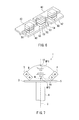
- FIG. 1 is a perspective view showing the general configuration of a rotating field sensor according to a first embodiment of the invention.
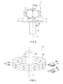
- FIG. 2 is a side view showing the general configuration of the rotating field sensor according to the first embodiment of the invention.
- FIG. 3 is a circuit diagram showing the configuration of the rotating field sensor according to the first embodiment of the invention.
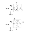
- FIG. 4A is an explanatory diagram illustrating the definitions of directions and angles in the first embodiment of the invention.
- FIG. 4B is an explanatory diagram illustrating the definitions of directions and angles in the first embodiment of the invention.
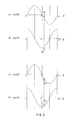
- FIG. 5 is a waveform chart showing the output signals of first to fourth detection circuits of the first embodiment of the invention.
- FIG. 6 is a perspective view showing part of an MR element in the rotating field sensor shown in FIG. 3 .
- FIG. 7 is a side view showing the general configuration of a rotating field sensor of a first modification example of the first embodiment of the invention.
- FIG. 8 is a side view showing the general configuration of a rotating field sensor of a second modification example of the first embodiment of the invention.
- FIG. 9 is a perspective view showing the general configuration of a rotating field sensor according to a second embodiment of the invention.
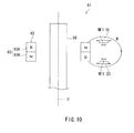
- FIG. 10 is a side view showing the general configuration of the rotating field sensor according to the second embodiment of the invention.
- FIG. 11 is a perspective view showing the general configuration of a rotating field sensor of a modification example of the second embodiment of the invention.
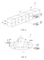
- FIG. 12 is a perspective view showing the general configuration of a rotating field sensor according to a third embodiment of the invention.
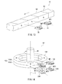
- FIG. 13 is a perspective view showing the general configuration of a rotating field sensor of a modification example of the third embodiment of the invention.
- FIG. 14 is a perspective view showing the general configuration of a rotating field sensor according to a fourth embodiment of the invention.
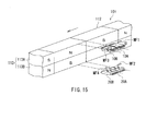
- FIG. 15 is a perspective view showing the general configuration of a rotating field sensor of a modification example of the fourth embodiment of the invention.
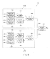
- FIG. 16 is a block diagram showing the configuration of the rotating field sensor according to the fourth embodiment of the invention.
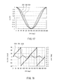
- FIG. 17 is a waveform chart showing how the output signals of the detection circuits of the rotating field sensor according to the fourth embodiment of the invention are distorted in waveform.
- FIG. 18 is a waveform chart showing the relationship between a first detected angle value and a first angular error in the fourth embodiment of the invention.
- FIG. 19 is an explanatory diagram showing the operation of reducing an angular error in the fourth embodiment of the invention.
- FIG. 20 is a waveform chart showing the relationship between a detected angle value and an angular error in the fourth embodiment of the invention.
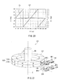
- FIG. 21 is a perspective view showing the general configuration of a rotating field sensor according to a fifth embodiment of the invention.
- FIG. 22 is a perspective view showing the general configuration of a rotating field sensor of a modification example of the fifth embodiment of the invention.
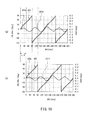
- FIG. 23 is a waveform chart showing the relationship between a first partial magnetic field, a first detected angle value, and a first angular error in the fifth embodiment of the invention.
- FIG. 24 is an explanatory diagram showing the operation of reducing an angular error in the fifth embodiment of the invention.
- FIG. 25 is a waveform chart showing the relationship between a detected angle value and an angular error in the fifth embodiment of the invention.
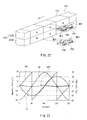
- FIG. 26 is a perspective view showing the general configuration of a rotating field sensor according to a sixth embodiment of the invention.
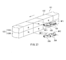
- FIG. 27 is a perspective view showing the general configuration of a rotating field sensor of a modification example of the sixth embodiment of the invention.
- FIG. 1 is a perspective view showing the general configuration of the rotating field sensor according to the present embodiment.
- FIG. 2 is a side view showing the general configuration of the rotating field sensor according to the present embodiment.
- FIG. 4A and FIG. 4B are explanatory diagrams illustrating the definitions of directions and angles in the present embodiment.
- a rotating field sensor 1 detects the angle that the direction of a rotating magnetic field in a reference position forms with respect to a reference direction.
- the rotating magnetic field includes a first partial magnetic field MF 1 in a first position and a second partial magnetic field MF 2 in a second position.
- the first partial magnetic field MF 1 and the second partial magnetic field MF 2 differ in direction by 180° and rotate in the same direction of rotation.
- the rotating field sensor 1 includes: a field generation unit 2 that generates the rotating magnetic field; a first detection unit 10 that detects a first applied field in the first position; and a second detection unit 20 that detects a second applied field in the second position.
- the first applied field includes the first partial magnetic field MF 1 as its main component.
- the second applied field includes the second partial magnetic field MF 2 as its main component.
- the first detection unit 10 is shown in a position separate from the arrow that represents the first partial magnetic field MF 1
- the second detection unit 20 is shown in a position separate from the arrow that represents the second partial magnetic field MF 2 .
- the first detection unit 10 is located in the first position where the first partial magnetic field MF 1 occurs, and the second detection unit 20 is located in the second position where the second partial magnetic field MF 2 occurs.
- the definitions of directions and angles will be described in detail later.
- the field generation unit 2 includes a disc part 5 , and a pair of magnets 3 and 4 attached to the disc part 5 .
- the disc part 5 is attached to one axial end of a rotating shaft 6 which is the object whose rotational position is to be detected.
- the rotating shaft 6 rotates about its center axis. With the rotation, the field generation unit 2 also rotates about the center of rotation C including the center axis of the rotating shaft 6 .
- the pair of magnets 3 and 4 are arranged in symmetrical positions with respect to a virtual plane that includes the center of rotation C.
- the lower surface in FIG. 1 and FIG. 2 will be defined as a “bottom surface”, and the upper surface in FIG. 1 and FIG.
- the magnets 3 and 4 are fixed to the top surface of the disc part 5 .
- the one end of the rotating shaft 6 is fixed to the bottom surface of the disc part 5 .
- the magnets 3 and 4 are rotated about the center of rotation C, whereby a rotating magnetic field is generated based on the magnetic field generated by the magnets 3 and 4 .
- Each of the magnets 3 and 4 has an N pole and an S pole.
- the N and S poles of the magnet 3 are arranged in the order of the S pole and the N pole from the top surface of the disc part 5 .
- the N and S poles of the magnet 4 are arranged in the order of the N pole and the S pole from the top surface of the disc part 5 .
- the direction of the rotating magnetic field generated by the pair of magnets 3 and 4 rotates about the center of rotation C with the rotation of the field generation unit 2 .
- FIG. 1 and FIG. 2 the major portion of the magnetic flux from the N pole of the magnet 3 to the S pole of the magnet 4 and the major portion of the magnetic flux from the N pole of the magnet 4 to the S pole of the magnet 3 are shown by curves designated by symbol M.
- the magnetic flux from the N pole of the magnet 3 to the S pole of the magnet 4 produces most of the first partial magnetic field MF 1 in the first position.
- the magnetic flux from the N pole of the magnet 4 to the S pole of the magnet 3 produces most of the second partial magnetic field MF 2 in the second position.
- the first and second detection units 10 and 20 are arranged above the top surface of the disc part 5 , between the magnets 3 and 4 . More specifically, in the present embodiment, the first detection unit 10 is located in the first position on the center of rotation C where the first partial magnetic field MF 1 occurs, and the second detection unit 20 is located in the second position on the center of rotation C where the second partial magnetic field MF 2 occurs. In FIG. 1 and FIG. 2 , the first detection unit 10 and the second detection unit 20 are shown as separate members. However, the first detection unit 10 and the second detection unit 20 may be integrated with each other as long as they are located in the first position and the second position, respectively.
- the direction of the first partial magnetic field MF 1 is from the N pole of the magnet 3 to the S pole of the magnet 4 .
- the direction of the second partial magnetic field MF 2 is from the N pole of the magnet 4 to the S pole of the magnet 3 .
- the direction of the first partial magnetic field MF 1 and that of the second partial magnetic field MF 2 are different from each other by 180°.
- the rotation of the field generation unit 2 rotates the first partial magnetic field MF 1 and the second partial magnetic field MF 2 in the same direction of rotation.
- FIG. 4A illustrates the definitions of directions and angles in the first position.
- FIG. 4B illustrates the definitions of directions and angles in the second position.
- a direction that is parallel to the center of rotation C shown in FIG. 1 and FIG. 2 and is away from the top surface of the disc part 5 will be defined as the Z direction.
- two mutually-orthogonal directions on a virtual plane perpendicular to the Z direction will be defined as the X direction and Y direction.
- the X direction is shown as the direction toward the right, and the Y direction is shown as the upward direction.
- the direction opposite to the X direction will be defined as the ⁇ X direction
- the direction opposite to the Y direction will be defined as the ⁇ Y direction.
- the first position is where the first detection unit 10 detects the first applied field.
- the first position is located on the center of rotation C, above the top surface of the disc part 5 .
- the arrow designated by symbol “D 1 ” in FIG. 4A shows the direction with respect to which the first detection unit 10 indicates the direction DM 1 of the first applied field.
- the direction D 1 coincides with the Y direction.
- the first applied field includes the first partial magnetic field MF 1 as its main component.
- the direction DM 1 of the first applied field and the direction of the first partial magnetic field MF 1 shall rotate clockwise in FIG. 4A .
- the second position is where the second detection unit 20 detects the second applied field.
- the second position is located on the center of rotation C, above the top surface of the disc part 5 , and is located closer to the top surface of the disc part 5 than is the first position.
- the arrow designated by symbol “D 2 ” in FIG. 4B shows the direction with respect to which the second detection unit 20 indicates the direction DM 2 of the second applied field.
- the direction D 1 and the direction D 2 is different from each other by 180°.
- the direction D 2 coincides with the ⁇ Y direction.
- the second applied field includes the second partial magnetic field MF 2 as its main component.
- the direction DM 2 of the second applied field and the direction of the second partial magnetic field MF 2 shall rotate clockwise in FIG. 4B .
- the reference position and the reference direction may coincide with the first position and the direction D 1 , respectively, or with the second position and the direction D 2 , respectively, or may be any position and direction different from those positions and directions.
- the direction D 1 and the direction D 2 are different from each other by 180°.
- the direction of the first partial magnetic field MF 1 and that of the second partial magnetic field MF 2 are also different from each other by 180°. Therefore, the angle that the direction of the first partial magnetic field MF 1 forms with respect to the direction D 1 is equal to the angle that the direction of the second partial magnetic field MF 2 forms with respect to the direction D 2 . If the first applied field consists only of the first partial magnetic field MF 1 and the second applied field consists only of the second partial magnetic field MF 2 , the angle that the direction DM 1 of the first applied field forms with respect to the direction D 1 is equal to the angle that the direction DM 2 of the second applied field forms with respect to the direction D 2 .
- FIG. 4A and FIG. 4B show the angle ⁇ .
- the angle ⁇ will be expressed in a positive value when seen clockwise from the direction D 1 or D 2 , and in a negative value when seen counterclockwise from the direction D 1 or D 2 .
- the rotating field sensor 1 detects components of the first applied field in two reference directions and components of the second applied field in two reference directions, thereby detecting the angle that the direction of the rotating magnetic field in a reference position forms with respect to a reference direction.
- the reference direction for one component of the first applied field will be referred to as a first direction.
- the reference direction for another component of the first applied field will be referred to as a second direction.
- the reference direction for one component of the second applied field will be referred to as a third direction.
- the reference direction for another component of the second applied field will be referred to as a fourth direction.
- the first direction and the third direction are parallel to each other.
- the second direction and the fourth direction are parallel to each other. In the present embodiment, in particular, the first direction and the third direction are different from each other by 180°, and the second direction and the fourth direction are different from each other by 180°.
- the direction D 1 and the direction D 2 may be the same as the first direction and the third direction, respectively, or as the second direction and the fourth direction, respectively, or may be any directions different from those directions.
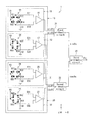
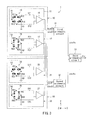
- FIG. 3 is a circuit diagram showing the configuration of the rotating field sensor 1 .
- the rotating field sensor 1 includes the first detection unit 10 and the second detection unit 20 .
- the first detection unit 10 detects the first applied field.
- the first detection unit 10 has a first detection circuit 11 that detects the intensity of the component of the first applied field in the first direction and outputs a signal indicating the intensity, and a second detection circuit 12 that detects the intensity of the component of the first applied field in the second direction and outputs a signal indicating the intensity.
- the second detection unit 20 detects the second applied field.
- the second detection unit 20 has a third detection circuit 21 that detects the intensity of the component of the second applied field in the third direction and outputs a signal indicating the intensity, and a fourth detection circuit 22 that detects the intensity of the component of the second applied field in the fourth direction and outputs a signal indicating the intensity.
- the output signals of the first to fourth detection circuits 11 , 12 , 21 , and 22 have the same period.
- the period of the output signals of the first to fourth detection circuits 11 , 12 , 21 , and 22 will be referred to as period T.
- the output signal of the second detection circuit 12 differs from the output signal of the first detection circuit 11 in phase by an odd number of times 1 ⁇ 4 the period T.
- the output signal of the third detection circuit 21 differs from the output signal of the first detection circuit 11 in phase by an integer multiple of 1 ⁇ 2 the period T.
- the output signal of the fourth detection circuit 22 differs from the output signal of the third detection circuit 21 in phase by an odd number of times 1 ⁇ 4 the period T.
- the rotating field sensor 1 further includes first to third arithmetic circuits 31 , 32 , and 33 .
- the first arithmetic circuit 31 generates a first signal that has a correspondence relationship with both the intensity of the component of the first applied field in the first direction and the intensity of the component of the second applied field in the third direction, based on the output signals of the first and third detection circuits 11 and 21 .
- the second arithmetic circuit 32 generates a second signal that has a correspondence relationship with both the intensity of the component of the first applied field in the second direction and the intensity of the component of the second applied field in the fourth direction, based on the output signals of the second and fourth detection circuits 12 and 22 .
- the third arithmetic circuit 33 calculates a detected angle value ⁇ s that has a correspondence relationship with the angle that the direction of the rotating magnetic field in the reference position forms with respect to the reference direction.
- the first to third arithmetic circuits 31 , 32 , and 33 can be implemented by a single microcomputer, for example. The method of generating the first and second signals and the method of calculating ⁇ s will be described in detail later.
- Each of the first to fourth detection circuits 11 , 12 , 21 , and 22 includes at least one magnetic detection element.
- Each of the first to fourth detection circuits 11 , 12 , 21 , and 22 may include, as the at least one magnetic detection element, a pair of magnetic detection elements connected in series.
- each of the first to fourth detection circuits 11 , 12 , 21 , and 22 may have a Wheatstone bridge circuit that includes a first pair of magnetic detection elements connected in series and a second pair of magnetic detection elements connected in series. The following description will deal with the case where each of the first to fourth detection circuits 11 , 12 , 21 , and 22 has such a Wheatstone bridge circuit.
- the first detection circuit 11 has a Wheatstone bridge circuit 14 and a difference detector 15 .
- the Wheatstone bridge circuit 14 includes a power supply port V 1 , a ground port G 1 , two output ports E 11 and E 12 , a first pair of magnetic detection elements R 11 and R 12 connected in series, and a second pair of magnetic detection elements R 13 and R 14 connected in series.
- One end of each of the magnetic detection elements R 11 and R 13 is connected to the power supply port V 1 .
- the other end of the magnetic detection element R 11 is connected to one end of the magnetic detection element R 12 and the output port E 11 .
- the other end of the magnetic detection element R 13 is connected to one end of the magnetic detection element R 14 and the output port E 12 .
- each of the magnetic detection elements R 12 and R 14 is connected to the ground port G 1 .
- a power supply voltage of predetermined magnitude is applied to the power supply port V 1 .
- the ground port G 1 is grounded.
- the difference detector 15 outputs to the first arithmetic circuit 31 a signal that corresponds to the potential difference between the output ports E 11 and E 12 .
- the second detection circuit 12 has a Wheatstone bridge circuit 16 and a difference detector 17 .
- the Wheatstone bridge circuit 16 includes a power supply port V 2 , a ground port G 2 , two output ports E 21 and E 22 , a first pair of magnetic detection elements R 21 and R 22 connected in series, and a second pair of magnetic detection elements R 23 and R 24 connected in series.
- One end of each of the magnetic detection elements R 21 and R 23 is connected to the power supply port V 2 .
- the other end of the magnetic detection element R 21 is connected to one end of the magnetic detection element R 22 and the output port E 21 .
- the other end of the magnetic detection element R 23 is connected to one end of the magnetic detection element R 24 and the output port E 22 .
- each of the magnetic detection elements R 22 and R 24 is connected to the ground port G 2 .
- a power supply voltage of predetermined magnitude is applied to the power supply port V 2 .
- the ground port G 2 is grounded.
- the difference detector 17 outputs to the second arithmetic circuit 32 a signal that corresponds to the potential difference between the output ports E 21 and E 22 .
- the third detection circuit 21 has a Wheatstone bridge circuit 24 and a difference detector 25 .
- the Wheatstone bridge circuit 24 includes a power supply port V 3 , a ground port G 3 , two output ports E 31 and E 32 , a first pair of magnetic detection elements R 31 and R 32 connected in series, and a second pair of magnetic detection elements R 33 and R 34 connected in series.
- One end of each of the magnetic detection elements R 31 and R 33 is connected to the power supply port V 3 .
- the other end of the magnetic detection element R 31 is connected to one end of the magnetic detection element R 32 and the output port E 31 .
- the other end of the magnetic detection element R 33 is connected to one end of the magnetic detection element R 34 and the output port E 32 .
- each of the magnetic detection elements R 32 and R 34 is connected to the ground port G 3 .
- a power supply voltage of predetermined magnitude is applied to the power supply port V 3 .
- the ground port G 3 is grounded.
- the difference detector 25 outputs to the first arithmetic circuit 31 a signal that corresponds to the potential difference between the output ports E 31 and E 32 .
- the fourth detection circuit 22 has a Wheatstone bridge circuit 26 and a difference detector 27 .
- the Wheatstone bridge circuit 26 includes a power supply port V 4 , a ground port G 4 , two output ports E 41 and E 42 , a first pair of magnetic detection elements R 41 and R 42 connected in series, and a second pair of magnetic detection elements R 43 and R 44 connected in series.
- One end of each of the magnetic detection elements R 41 and R 43 is connected to the power supply port V 4 .
- the other end of the magnetic detection element R 41 is connected to one end of the magnetic detection element R 42 and the output port E 41 .
- the other end of the magnetic detection element R 43 is connected to one end of the magnetic detection element R 44 and the output port E 42 .
- each of the magnetic detection elements R 42 and R 44 is connected to the ground port G 4 .
- a power supply voltage of predetermined magnitude is applied to the power supply port V 4 .
- the ground port G 4 is grounded.
- the difference detector 27 outputs to the second arithmetic circuit 32 a signal that corresponds to the potential difference between the output ports E 41 and E 42 .
- all the magnetic detection elements included in the Wheatstone bridge circuits (hereinafter, referred to as bridge circuits) 14 , 16 , 24 , and 26 are MR elements, or TMR elements in particular.
- GMR elements may be employed instead of the TMR elements.
- the TMR elements or GMR elements each have a magnetization pinned layer whose direction of magnetization is pinned, a free layer whose direction of magnetization varies according to the direction of a magnetic field applied thereto, and a nonmagnetic layer disposed between the magnetization pinned layer and the free layer.
- the nonmagnetic layer is a tunnel barrier layer.
- the nonmagnetic layer is a nonmagnetic conductive layer.
- the TMR elements or GMR elements vary in resistance depending on the angle that the direction of magnetization of the free layer forms with respect to the direction of magnetization of the magnetization pinned layer.
- the resistance reaches its minimum value when the foregoing angle is 0°.
- the resistance reaches its maximum value when the foregoing angle is 180°.
- the magnetic detection elements included in the bridge circuits 14 , 16 , 24 , and 26 will be referred to as MR elements.
- the filled arrows indicate the directions of magnetization of the magnetization pinned layers in the MR elements.
- the hollow arrows indicate the directions of magnetization of the free layers in the MR elements.
- the magnetization pinned layers of the MR elements R 11 and R 14 are magnetized in a direction parallel to the first direction, and the magnetization pinned layers of the MR elements R 12 and R 13 are magnetized in a direction opposite to the direction of magnetization of the magnetization pinned layers of the MR elements R 11 and R 14 .
- the potential difference between the output ports E 11 and E 12 varies according to the intensity of the component of the first applied field in the first direction.
- the first direction therefore serves as a reference direction when the first detection circuit 11 detects the first applied field.
- the first detection circuit 11 detects the intensity of the component of the first applied field in the first direction, and outputs a signal that indicates the intensity. In the example shown in FIG.
- the magnetization pinned layers of the MR elements R 11 and R 14 are magnetized in the X direction
- the magnetization pinned layers of the MR elements R 12 and R 13 are magnetized in the ⁇ X direction.
- the first direction is the same as the X direction.
- the magnetization pinned layers of the MR elements R 21 and R 24 are magnetized in a direction parallel to the second direction, and the magnetization pinned layers of the MR elements R 22 and R 23 are magnetized in a direction opposite to the direction of magnetization of the magnetization pinned layers of the MR elements R 21 and R 24 .
- the potential difference between the output ports E 21 and E 22 varies according to the intensity of the component of the first applied field in the second direction.
- the second direction therefore serves as a reference direction when the second detection circuit 12 detects the first applied field.
- the second detection circuit 12 detects the intensity of the component of the first applied field in the second direction, and outputs a signal that indicates the intensity. In the example shown in FIG.
- the magnetization pinned layers of the MR elements R 21 and R 24 are magnetized in the Y direction
- the magnetization pinned layers of the MR elements R 22 and R 23 are magnetized in the ⁇ Y direction.
- the second direction is the same as the Y direction.
- the magnetization pinned layers of the MR elements R 31 and R 34 are magnetized in a direction parallel to the third direction, and the magnetization pinned layers of the MR elements R 32 and R 33 are magnetized in a direction opposite to the direction of magnetization of the magnetization pinned layers of the MR elements R 31 and R 34 .
- the potential difference between the output ports E 31 and E 32 varies according to the intensity of the component of the second applied field in the third direction.
- the third direction therefore serves as a reference direction when the third detection circuit 21 detects the second applied field.
- the third detection circuit 21 detects the intensity of the component of the second applied field in the third direction, and outputs a signal that indicates the intensity. In the example shown in FIG.
- the magnetization pinned layers of the MR elements R 31 and R 34 are magnetized in the ⁇ X direction, and the magnetization pinned layers of the MR elements R 32 and R 33 are magnetized in the X direction.
- the third direction is the same as the X direction.
- the magnetization pinned layers of the MR elements R 41 and R 44 are magnetized in a direction parallel to the fourth direction, and the magnetization pinned layers of the MR elements R 42 and R 43 are magnetized in a direction opposite to the direction of magnetization of the magnetization pinned layers of the MR elements R 41 and R 44 .
- the potential difference between the output ports E 41 and E 42 varies according to the intensity of the component of the second applied field in the fourth direction.
- the fourth direction therefore serves as a reference direction when the fourth detection circuit 22 detects the second applied field.
- the fourth detection circuit 22 detects the intensity of the component of the second applied field in the fourth direction, and outputs a signal that indicates the intensity. In the example shown in FIG.
- the magnetization pinned layers of the MR elements R 41 and R 44 are magnetized in the ⁇ Y direction, and the magnetization pinned layers of the MR elements R 42 and R 43 are magnetized in the Y direction.
- the fourth direction is the same as the Y direction.
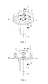
- FIG. 6 is a perspective view showing a part of an MR element in the rotating field sensor 1 shown in FIG. 3 .
- the MR element has a plurality of lower electrodes, a plurality of MR films, and a plurality of upper electrodes.
- the plurality of lower electrodes 42 are arranged on a not-shown substrate.
- Each of the lower electrodes 42 has a long slender shape.
- Two lower electrodes 42 adjoining in the longitudinal direction of the lower electrodes 42 have a gap therebetween.
- MR films 50 are provided on the top surfaces of the lower electrodes 42 , near opposite ends in the longitudinal direction.
- Each of the MR films 50 includes a free layer 51 , a nonmagnetic layer 52 , a magnetization pinned layer 53 , and an antiferromagnetic layer 54 that are stacked in this order, the free layer 51 being closest to the lower electrode 42 .
- the free layer 51 is electrically connected to the lower electrode 42 .
- the antiferromagnetic layer 54 is made of an antiferromagnetic material.
- the antiferromagnetic layer 54 is in exchange coupling with the magnetization pinned layer 53 so as to pin the direction of magnetization of the magnetization pinned layer 53 .
- the plurality of upper electrodes 43 are arranged over the plurality of MR films 50 .
- Each of the upper electrodes 43 has a long slender shape, and establishes electrical connection between the respective antiferromagnetic layers 54 of two adjoining MR films 50 that are arranged on two lower electrodes 42 adjoining in the longitudinal direction of the lower electrodes 42 .
- the plurality of MR films 50 in the MR element shown in FIG. 6 are connected in series by the plurality of lower electrodes 42 and the plurality of upper electrodes 43 .
- the layers 51 to 54 of the MR films 50 may be stacked in an order reverse to that shown in FIG. 6 .
- the first arithmetic circuit 31 generates the first signal based on the output signals of the first and third detection circuits 11 and 21
- the second arithmetic circuit 32 generates the second signal based on the output signals of the second and fourth detection circuits 12 and 22
- the third arithmetic circuit 33 calculates the detected angle value ⁇ s that has a correspondence relationship with the angle that the direction of the rotating magnetic field in the reference position forms with respect to the reference direction.
- noise field H ext the noise field
- the directions of magnetization of the magnetization pinned layers of the MR elements in the second detection circuit 12 are orthogonal to those of the magnetization pinned layers of the MR elements in the first detection circuit 11 .
- the output signal of the first detection circuit 11 traces a sine waveform
- the output signal of the second detection circuit 12 traces a cosine waveform.
- the output signal of the second detection circuit 12 differs from that of the first detection circuit 11 in phase by 1 ⁇ 4 the period T, i.e., by ⁇ /2(90°).
- the output signal of the first detection circuit 11 When the angle ⁇ shown in FIG. 4A is greater than 0° and smaller than 180°, the output signal of the first detection circuit 11 has a positive value. When the angle ⁇ shown in FIG. 4A is greater than 180° and smaller than 360°, the output signal of the first detection circuit 11 has a negative value. When the angle ⁇ shown in FIG. 4A is equal to or greater than 0° and smaller than 90° and when the angle ⁇ is greater than 270° and smaller than or equal to 360°, the output signal of the second detection circuit 12 has a positive value. When the angle ⁇ is greater than 90° and smaller than 270°, the output signal of the second detection circuit 12 has a negative value.
- the output signal of the first detection circuit 11 will be denoted by sin ⁇ 1
- the output signal of the second detection circuit 12 will be denoted by cos ⁇ 1
- the output signal sin ⁇ 1 is a signal that indicates the intensity of the component of the first applied field in the first direction (the X direction).
- the output signal cos ⁇ 1 is a signal that indicates the intensity of the component of the first applied field in the second direction (the Y direction).
- the arrow with symbol H ext indicates the direction of the noise field H ext that is applied to the first detection unit 10 .
- the noise field H ext includes a first component in a direction parallel to the X direction and a second component in a direction parallel to the Y direction.
- the first component of the noise field H ext is in the same direction as the first direction (i.e., in the X direction)
- the second component of the noise field H ext is in the direction opposite to the second direction (i.e., in the ⁇ Y direction).
- the first applied field is a composite magnetic field resulting from a combination of the first partial magnetic field MF 1 and the noise field H ext .
- the output signal sin ⁇ 1 includes a noise component of a positive value that results from the first component of the noise field H ext
- the output signal cos ⁇ 1 includes a noise component of a negative value that results from the second component of the noise field H ext .
- the directions of magnetization of the magnetization pinned layers of the MR elements in the fourth detection circuit 22 are orthogonal to those of the magnetization pinned layers of the MR elements in the third detection circuit 21 .
- the output signal of the third detection circuit 21 traces a sine waveform
- the output signal of the fourth detection circuit 22 traces a cosine waveform.
- the output signal of the fourth detection circuit 22 differs from that of the third detection circuit 21 in phase by 1 ⁇ 4 the period T, i.e., by ⁇ /2(90°).
- the output signal of the third detection circuit 21 When the angle ⁇ shown in FIG. 4B is greater than 0° and smaller than 180°, the output signal of the third detection circuit 21 has a positive value. When the angle ⁇ shown in FIG. 4B is greater than 180° and smaller than 360°, the output signal of the third detection circuit 21 has a negative value. When the angle ⁇ shown in FIG. 4B is equal to or greater than 0° and smaller than 90° and when the angle ⁇ is greater than 270° and smaller than or equal to 360°, the output signal of the fourth detection circuit 22 has a positive value. When the angle ⁇ is greater than 90° and smaller than 270°, the output signal of the fourth detection circuit 22 has a negative value.
- the output signal of the third detection circuit 21 will be denoted by sin ⁇ 2
- the output signal of the fourth detection circuit 22 will be denoted by cos ⁇ 2
- the output signal sin ⁇ 2 is a signal that indicates the intensity of the component of the second applied field in the third direction (the ⁇ X direction).
- the output signal cos ⁇ 2 is a signal that indicates the intensity of the component of the second applied field in the fourth direction (the ⁇ Y direction).
- the second detection unit 20 undergoes a noise field H ext whose direction and magnitude are the same as those of the noise field H ext that is applied to the first detection unit 10 .
- the noise field H ext includes a first component in a direction parallel to the X direction and a second component in a direction parallel to the Y direction.
- the first component of the noise field H ext is in the direction opposite to the third direction (i.e., in the X direction), and the second component of the noise field H ext is in the same direction as the fourth direction (i.e., in the ⁇ Y direction).
- the second applied field is a composite magnetic field resulting from a combination of the second partial magnetic field MF 2 and the noise field H ext .
- the output signal sin ⁇ 2 includes a noise component of a negative value that results from the first component of the noise field H ext
- the output signal cos ⁇ 2 includes a noise component of a positive value that results from the second component of the noise field H ext .
- the noise component included in the output signal sin ⁇ 2 has the same magnitude as the magnitude Es of the noise component included in the output signal sin ⁇ 1 , with an opposite sign.
- the noise component included in the output signal cos ⁇ 2 has the same magnitude as the magnitude Ec of the noise component included in the output signal cos ⁇ 1 , with an opposite sign.
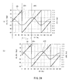
- FIG. 5 is an explanatory diagram showing the waveforms of the output signals of the first to fourth detection circuits 11 , 12 , 21 , and 22 .
- Portions (a) to (d) of FIG. 5 show the waveforms of the output signals sin ⁇ 1 , cos ⁇ 1 , sin ⁇ 2 , and cos ⁇ 2 , respectively.
- the direction of the first partial magnetic field MF 1 and that of the second partial magnetic field MF 2 are different from each other by 180°.
- the first direction and the third direction are also different from each other by 180°.
- the output signal sin ⁇ 1 and the output signal sin ⁇ 2 therefore have the same phase.
- the second direction and the fourth direction are also different from each other by 180°.
- the output signal cos ⁇ 1 and the output signal cos ⁇ 2 therefore have the same phase.
- FIG. 5 also shows the noise components included in the respective output signals.
- the noise field H ext is a pulsed noise field that is applied for a time sufficiently shorter than the period T.
- the output signal sin ⁇ 1 includes a noise component of a positive value resulting from the noise field H ext
- the output signal sin ⁇ 2 includes a noise component of a negative value resulting from the noise field H ext .
- the output signal cos ⁇ 1 includes a noise component of a negative value resulting from the noise field H ext
- the output signal cos ⁇ 2 includes a noise component of a positive value resulting from the noise field H ext .
- the noise component included in the output signal sin ⁇ 1 has a positive value (Es) and the noise component included in the output signal sin ⁇ 2 has a negative value ( ⁇ Es).
- the noise component included in the output signal cos ⁇ 1 has a negative value ( ⁇ Ec) and the noise component included in the output signal cos ⁇ 2 has a positive value (Ec).
- the first arithmetic circuit 31 Based on the output signal sin ⁇ 1 of the first detection circuit 11 and the output signal sin ⁇ 2 of the third detection circuit 21 , the first arithmetic circuit 31 generates the first signal sin ⁇ s that has a correspondence relationship with both the intensity of the component of the first applied field in the first direction and the intensity of the component of the second applied field in the third direction.
- the output signal sin ⁇ 1 and the output signal sin ⁇ 2 can be averaged into the first signal sin ⁇ s.
- the first signal sin ⁇ s is given by the following equation (5):
- the first signal sin ⁇ s is equal to sin ⁇ .
- the noise component included in the output signal sin ⁇ 1 and that included in the output signal sin ⁇ 2 have a value with opposite signs, the noise component included in the output signal sin ⁇ 1 and that included in the output signal sin ⁇ 2 cancel each other out when the first arithmetic circuit 31 generates the first signal sin ⁇ s.
- the output signal sin ⁇ 1 indicating the intensity of the component of the first applied field in the first direction and the output signal sin ⁇ 2 indicating the intensity of the second applied field in the third direction both include sin ⁇ .
- the first signal sin ⁇ s therefore has a correspondence relationship with both the intensity of the component of the first applied field in the first direction and the intensity of the component of the second applied field in the third direction.
- the output signal sin ⁇ 1 and the output signal sin ⁇ 2 are averaged in the equation (5), the output signal sin ⁇ 1 and the output signal sin ⁇ 2 may be added into the first signal sin ⁇ s. In this case also, the noise component included in the output signal sin ⁇ 1 and that included in the output signal sin ⁇ 2 cancel each other out.
- the second arithmetic circuit 32 Based on the output signal cos ⁇ 1 of the second detection circuit 12 and the output signal cos ⁇ 2 of the fourth detection circuit 22 , the second arithmetic circuit 32 generates the second signal cos ⁇ s that has a correspondence relationship with both the intensity of the component of the first applied field in the second direction and the intensity of the component of the second applied field in the fourth direction.
- the output signal cos ⁇ 1 and the output signal cos ⁇ 2 can be averaged into the second signal cos ⁇ s.
- the second signal cos ⁇ s is given by the following equation (6):
- the second signal cos ⁇ s is equal to cos ⁇ .
- the noise component included in the output signal cos ⁇ 1 and that included in the output signal cos ⁇ 2 have a value with opposite signs, the noise component included in the output signal cos ⁇ 1 and that included in the output signal cos ⁇ 2 cancel each other out when the second arithmetic circuit 32 generates the second signal cos ⁇ s.
- the output signal cos ⁇ 1 indicating the intensity of the component of the first applied field in the second direction and the output signal cos ⁇ 2 indicating the intensity of the second applied field in the fourth direction both include cos ⁇ .
- the second signal cos ⁇ s therefore has a correspondence relationship with both the intensity of the component of the first applied field in the second direction and the intensity of the component of the second applied field in the fourth direction.
- the output signal cos ⁇ 1 and the output signal cos ⁇ 2 may be added into the second signal cos ⁇ s.
- the noise component included in the output signal cos ⁇ 1 and that included in the output signal cos ⁇ 2 cancel each other out.
- the third arithmetic circuit 33 calculates the detected angle value ⁇ s and the relationship between the detected angle value ⁇ s and the noise field H ext. Based on the first signal sin ⁇ s and the second signal cos ⁇ s, the third arithmetic circuit 33 calculates the detected angle value ⁇ s that has a correspondence relationship with the angle that the direction of the rotating magnetic field in the reference position forms with respect to the reference direction. Specifically, for example, the third arithmetic circuit 33 calculates ⁇ s by the following equation (7):
- ⁇ in the equation (7) has two solutions with a difference of 180° in value. Which of the two solutions of ⁇ in the equation (7) is the true solution to ⁇ can be determined from the combination of positive and negative signs on sin ⁇ and cos ⁇ . More specifically, if sin ⁇ is positive in value, ⁇ is greater than 0° and smaller than 180°. If sin ⁇ is negative in value, ⁇ is greater than 180° and smaller than 360°. If cos ⁇ is positive in value, ⁇ is equal to or greater than 0° and smaller than 90°, or is greater than 270° and smaller than or equal to 360°. If cos ⁇ is negative in value, ⁇ is greater than 90° and smaller than 270°.
- the third arithmetic circuit 33 determines ⁇ in the range of 360°, based on the equation (7) and the foregoing determination of the combination of positive and negative signs on sin ⁇ and cos ⁇ .
- the detected angle value ⁇ s is equal to the angle ⁇ .
- the noise components included in the respective output signals sin ⁇ 1 and sin ⁇ 2 cancel each other out when the first signal sin ⁇ s is generated, and the noise components included in the respective output signals cos ⁇ 1 and cos ⁇ 2 cancel each other out when the second signal cos ⁇ s is generated. Consequently, it is possible for the third arithmetic circuit 33 to calculate ⁇ s by using the first signal sin ⁇ s containing no noise component and the second signal cos ⁇ s containing no noise component.
- the direction of the noise field H ext is opposite to that in the case of FIG. 4A and FIG. 4B , the direction of the first component of the noise field H ext coincides with the ⁇ X direction, and the direction of the second component of the noise field H ext coincides with the Y direction. That is, in such a case, the noise component included in the output signal sin ⁇ 1 has a negative value, the noise component included in the output signal sin ⁇ 2 has a positive value, the noise component included in the output signal cos ⁇ 1 has a positive value, and the noise component included in the output signal cos ⁇ 2 has a negative value.
- the noise components included in the respective output signals sin ⁇ 1 and sin ⁇ 2 cancel each other out when the first signal sin ⁇ s is generated, and the noise components included in the respective output signals cos ⁇ 1 and cos ⁇ 2 cancel each other out when the second signal cos ⁇ s is generated.
- the detected angle value ⁇ s is calculated based on two output signals containing noise components.
- the noise components included in the respective output signals sin ⁇ 1 and sin ⁇ 2 have a value with opposite signs
- the noise components included in the respective output signals cos ⁇ 1 and cos ⁇ 2 have a value with opposite signs.
- the noise components included in the respective output signals sin ⁇ 1 and sin ⁇ 2 cancel each other out when the first signal sin ⁇ s is generated, and the noise components included in the respective output signals cos ⁇ 1 and cos ⁇ 2 cancel each other out when the second signal cos ⁇ s is generated.
- the first signal sin ⁇ s containing no noise component and the second signal cos ⁇ s containing no noise component are used to calculate the detected angle value ⁇ s. Consequently, according to the present embodiment, it is possible to reduce errors in the detected angle resulting from the noise field H ext .
- phase of the output signal cos ⁇ 1 is different from that of the output signal sin ⁇ 1 by 1 ⁇ 4 the period T
- the phase of the output signal sin ⁇ 2 is the same as that of the output signal sin ⁇ 1
- the phase of the output signal cos ⁇ 2 is different from that of the output signal sin ⁇ 2 by 1 ⁇ 4 the period T.
- phase of the output signal cos ⁇ 1 may be different from that of the output signal sin ⁇ 1 by an odd number of times 1 ⁇ 4 the period T
- the phase of the output signal sin ⁇ 2 may be different from that of the output signal sin ⁇ 1 by an integer multiple of 1 ⁇ 2 the period T
- the phase of the output signal cos ⁇ 2 may be different from that of the output signal sin ⁇ 2 by an odd number of times 1 ⁇ 4 the period T.
- the noise component included in the output signal sin ⁇ 1 and that included in the output signal sin ⁇ 2 have the same magnitude.
- the noise components may be different in magnitude.
- the value of the noise component included in the output signal sin ⁇ 1 and the value of the noise component included in the output signal sin ⁇ 2 are of opposite sign. Therefore, when calculating the first signal sin ⁇ s using the equation (5), the noise components included in the respective output signals sin ⁇ 1 and sin ⁇ 2 cancel each other out. This makes the magnitude of the noise component included in the first signal sin ⁇ s smaller than the average of the magnitudes of the noise components included in the output signals sin ⁇ 1 and sin ⁇ 2 .
- the noise component included in the first signal sin ⁇ s has a smaller magnitude as described above, it is possible to reduce errors in the detected angle that result from the noise field H ext .
- the noise component included in the output signal cos ⁇ 1 and that included in the output signal cos ⁇ 2 may be different in magnitude.
- the noise component included in the second signal cos ⁇ s has a smaller magnitude than the average of the magnitudes of the noise components included in the output signals cos ⁇ 1 and cos ⁇ 2 , and it is thus possible to reduce errors in the detected angle that result from the noise field H ext .
- the noise field H ext is a pulsed noise field.
- the noise field H ext may be one that makes no change in magnitude or direction with time, or may be one that varies periodically in magnitude and direction. In such cases also, it is possible to cancel out the noise components resulting from the noise field H ext .
- the first detection unit 10 including the first and second detection circuits 11 and 12 is located in the first position
- the second detection unit 20 including the third and fourth detection circuits 21 and 22 is located in the second position. This allows reducing the installation locations of the first to fourth detection circuits 11 , 12 , 21 , and 22 as compared to a case where the first to fourth detection circuits 11 , 12 , 21 , and 22 are installed in respective different positions.
- Each of the first to fourth detection circuits 11 , 12 , 21 , and 22 includes at least one MR element.
- the present embodiment since the installation locations of the first to fourth detection circuits 11 , 12 , 21 , and 22 are reduced as mentioned above, the installation locations of the MR elements included in the detection circuits 11 , 12 , 21 , and 22 are also reduced. Consequently, the present embodiment makes it possible to reduce the installation locations of the magnetic detection elements (MR elements) while reducing errors in the detected angle resulting from the noise field H ext .
- FIG. 7 is a side view showing the general configuration of the rotating field sensor 1 of the first modification example.
- the pair of magnets 3 and 4 are tilted with respect to the center of rotation C so that the distance between the magnets 3 and 4 increases with increasing distance from the top surface of the disc part 5 .
- the N and S poles of the magnet 3 are arranged obliquely to the center of rotation C, in the order of the S pole and the N pole in the direction away from the top surface of the disc part 5 .
- the N and S poles of the magnet 4 are arranged obliquely to the center of rotation C, in the order of the N pole and the S pole in the direction away from the top surface of the disc part 5 .
- FIG. 7 the major portion of the magnetic flux from the N pole of the magnet 3 to the S pole of the magnet 4 and the major portion of the magnetic flux from the N pole of the magnet 4 to the S pole of the magnet 3 are shown by the curve and the straight line each designated by symbol M.
- the major portions of these magnetic fluxes are shifted upward in FIG. 7 as compared with the case where the pair of magnets 3 and 4 are not tilted with respect to the center of rotation C ( FIG. 2 ). If the pair of magnets 3 and 4 are not tilted with respect to the center of rotation C, as shown in FIG. 2 , the major portion of the magnetic flux from the N pole of the magnet 4 to the S pole of the magnet 3 may pass below the top surface of the disc unit 5 .
- the second detection unit 20 it is sometimes difficult to locate the second detection unit 20 in an optimum position, i.e., the position where the major portion of the magnetic flux from the N pole of the magnet 4 to the S pole of the magnet 3 passes.
- the first partial magnetic field MF 1 and the second partial magnetic field MF 2 may have different intensities.
- a correcting calculation is preferably performed in consideration of the intensities of the first partial magnetic field MF 1 and the second partial magnetic field MF 2 .
- either one of the output signals sin ⁇ 1 and sin ⁇ 2 is multiplied by a predetermined coefficient to create a pair of corrected output signals such that the corrected output signals have the same magnitude with no noise component contained in the output signals sin ⁇ 1 and sin ⁇ 2 .
- the pair of corrected output signals is then used to generate the first signal sin ⁇ s.
- either one of the output signals cos ⁇ 1 and cos ⁇ 2 is multiplied by a predetermined coefficient to create a pair of corrected output signals such that the corrected output signals have the same magnitude with no noise component contained in the output signals cos ⁇ 1 and cos ⁇ 2 .
- the pair of corrected output signals is then used to generate the second signal cos ⁇ s.
- FIG. 8 is a side view showing the general configuration of the rotating field sensor 1 of the second modification example.
- the pair of magnets 3 and 4 are located away from the top surface of the disc part 5 .
- the field generation unit 2 of this modification example includes supporters 7 and 8 secured to the top surface of the disc part 5 .
- the magnets 3 and 4 are fixed on the supporters 7 and 8 , respectively.
- FIG. 8 the major portion of the magnetic flux from the N pole of the magnet 3 to the S pole of the magnet 4 and the major portion of the magnetic flux from the N pole of the magnet 4 to the S pole of the magnet 3 are shown by the curves designated by symbol M. These major portions of the magnetic fluxes are shifted upward in FIG. 8 as compared with the case where the magnets 3 and 4 are fixed to the top surface of the disc part 5 ( FIG. 2 ). Consequently, according to the second modification example, it is possible to install the second detection unit 20 in an optimum position easily, as with the first modification example. Moreover, the second modification example allows preventing the occurrence of a difference in intensity between the first partial magnetic field MF 1 and the second partial magnetic field MF 2 . This eliminates the need for the foregoing correcting calculation.
- FIG. 9 is a perspective view showing the general configuration of the rotating field sensor according to the present embodiment.
- FIG. 10 is a side view showing the general configuration of the rotating field sensor according to the present embodiment.
- the rotating field sensor 61 according to the present embodiment has a field generation unit 62 instead of the field generation unit 2 of the first embodiment.
- the field generation unit 62 has a ring-shaped magnet 63 .
- the magnet 63 is attached to a rotating shaft 66 which is the object whose rotational position is to be detected.
- the dot-and-dash line designated by symbol C shows the center of rotation including the center axis of the rotating shaft 66 .
- the magnet 63 is fixed to the rotating shaft 66 by not-shown fixing means so as to be symmetrical about the center of rotation C.
- the magnet 63 rotates about the center of rotation C along with the rotating shaft 66 . As a result, a rotating magnetic field occurs based on the magnetic field generated by the magnet 63 .
- the magnet 63 includes a first layer 63 A and a second layer 63 B.
- first and second layers 63 A and 63 B In each of the first and second layers 63 A and 63 B, one or more pairs of N and S poles are alternately arranged in a ring shape.
- the first layer 63 A and the second layer 63 B are stacked in the vertical direction (the direction parallel to the center of rotation C) in FIG. 9 and FIG. 10 .
- the N poles of the first layer 63 A are arranged to be vertically adjacent to the S poles of the second layer 63 B.
- the S poles of the first layer 63 A are arranged to be vertically adjacent to the N poles of the second layer 63 B.
- the first and second detection units 10 and 20 are located outside the outer periphery of the magnet 63 and arranged in the direction parallel to the center of rotation C.
- the position where the first detection unit 10 is located is the first position.
- the position where the second detection unit 20 is located is the second position.
- the first position lies above a virtual plane that includes the interface between the first layer 63 A and the second layer 63 B.
- the second position is below the virtual plane.
- the rotating magnetic field includes a first partial magnetic field MF 1 in the first position and a second partial magnetic field MF 2 in the second position. Magnetic fluxes in the vicinity of the first layer 63 A produce most of the first partial magnetic field MF 1 .
- the magnetic fluxes in the vicinity of the first layer 63 A include a magnetic flux between two different poles of the first and second layers 63 A and 63 B that are vertically adjacent to each other, and a magnetic flux between two different poles of the first layer 63 A that are adjacent to each other in the direction of rotation.
- Magnetic fluxes in the vicinity of the second layer 63 B produce most of the second partial magnetic field MF 2 .
- the magnetic fluxes in the vicinity of the second layer 6313 include a magnetic flux between two different poles of the first and second layers 63 A and 63 B that are vertically adjacent to each other, and a magnetic flux between two different poles of the second layer 63 B that are adjacent to each other in the direction of rotation. In FIG.
- the first partial magnetic field MF 1 and the second partial magnetic field MF 2 differ in direction by 180° and rotate in the same direction of rotation.
- the first detection unit 10 detects a first applied field in the first position.
- the first applied field includes the first partial magnetic field MF 1 as its main component.
- the second detection unit 20 detects a second applied field in the second position.
- the second applied field includes the second partial magnetic field MF 2 as its main component.
- a first direction serving as the reference direction for one component of the first applied field and a third direction serving as the reference direction for one component of the second applied field are different from each other by 180°.
- a second direction serving as the reference direction for another component of the first applied field and a fourth direction serving as the reference direction for another component of the second applied field are different from each other by 180°.
- each of the first layer 63 A and the second layer 63 B includes five pairs of N and S poles.
- One rotation of the magnet 63 produces five rotations of the first partial magnetic field MF 1 and the second partial magnetic field MF 2 .
- one period of the output signals of the detection circuits 11 , 12 , 21 , and 22 i.e., an electrical angle of 360°, is equivalent to a one-fifth rotation of the magnet 63 , i.e., an angle of rotation of 72° of the magnet 63 .
- FIG. 11 is a side view showing the general configuration of a rotating field sensor 61 of the modification example of the present embodiment.
- the rotating field sensor 61 of the modification example has a field generation unit 72 instead of the field generation unit 62 .
- the field generation unit 72 includes a magnet 73 that is long in one direction.
- the magnet 73 makes a straight movement in its longitudinal direction along with a straight movement of the object. As a result, a rotating magnetic field occurs based on the magnetic field generated by the magnet 73 .
- the magnet 73 includes a first layer 73 A and a second layer 73 B each of which has a plurality of pairs of N and S poles alternately arranged in a line.
- the first layer 73 A and the second layer 73 B are stacked in the vertical direction in FIG. 11 (the direction orthogonal to the direction of movement of the magnet 73 ).
- the N poles of the first layer 73 A are arranged to be vertically adjacent to the S poles of the second layer 73 B.
- the S poles of the first layer 73 A are arranged to be vertically adjacent to the N poles of the second layer 73 B.
- the first and second detection units 10 and 20 are located beside the magnet 73 and arranged in the vertical direction in FIG. 11 (the stacking direction of the first layer 73 A and the second layer 73 B).
- the position where the first detection unit 10 is located is the first position.
- the position where the second detection unit 20 is located is the second position.
- the first position lies above a virtual plane that includes the interface between the first layer 73 A and the second layer 73 B.
- the second position is below the virtual plane.
- the rotating magnetic field includes a first partial magnetic field MF 1 in the first position and a second partial magnetic field MF 2 in the second position. Magnetic fluxes in the vicinity of the first layer 73 A produce most of the first partial magnetic field MF 1 .
- the magnetic fluxes in the vicinity of the first layer 73 A include a magnetic flux between two different poles of the first and second layers 73 A and 73 B that are vertically adjacent to each other, and a magnetic flux between two different poles of the first layer 73 A that are adjacent to each other in the direction of movement of the magnet 73 .
- Magnetic fluxes in the vicinity of the second layer 73 B produce most of the second partial magnetic field MF 2 .
- the magnetic fluxes in the vicinity of the second layer 73 B include a magnetic flux between two different poles of the first and second layers 73 A and 73 B that are vertically adjacent to each other, and a magnetic flux between two different poles of the second layer 73 B that are adjacent to each other in the direction of movement of the magnet 73 .
- the first partial magnetic field MF 1 and the second partial magnetic field MF 2 differ in direction by 180° and rotate in the same direction of rotation.
- the first detection unit 10 detects a first applied field in the first position.
- the first applied field includes the first partial magnetic field MF 1 as its main component.
- the second detection unit 20 detects a second applied field in the second position.
- the second applied field includes the second partial magnetic field MF 2 as its main component.
- a first direction serving as the reference direction for one component of the first applied field and a third direction serving as the reference direction for one component of the second applied field are different from each other by 180°.
- a second direction serving as the reference direction for another component of the first applied field and a fourth direction serving as the reference direction for another component of the second applied field are different from each other by 180°.
- each of the first partial magnetic field MF 1 and the second partial magnetic pole MF 2 makes one rotation.
- one period of the output signals of the detection circuits 11 , 12 , 21 , and 22 i.e., an electrical angle of 360°, is equivalent to one pitch of the magnet 73 .
- FIG. 12 is a perspective view showing the general configuration of the rotating field sensor according to the present embodiment.
- the rotating field sensor 81 according to the present embodiment has a field generation unit 82 instead of the field generation unit 62 of the second embodiment.
- the field generation unit 82 has a ring-shaped magnet 83 .
- the magnet 83 is attached to a rotating shaft 66 which is the object whose rotational position is to be detected.
- the dot-and-dash line designated by symbol C shows the center of rotation including the center axis of the rotating shaft 66 .
- the magnet 83 is fixed to the rotating shaft 66 by not-shown fixing means so as to be symmetrical about the center of rotation C.
- the magnet 83 rotates about the center of rotation C along with the rotating shaft 66 . As a result, a rotating magnetic field occurs based on the magnetic field generated by the magnet 83 .
- the magnet 83 is composed of 2n pairs (n is an integer equal to or greater than 1) of N and S poles that are alternately arranged in a ring shape. In the example shown in FIG. 12 , the magnet 83 includes two pairs of N and S poles.
- the first and second detection units 10 and 20 are arranged with the magnet 83 therebetween, in symmetrical positions with respect to a virtual plane that includes the center of rotation C.
- the position where the first detection unit 10 is located is the first position.
- the position where the second detection unit 20 is located is the second position.
- the rotating magnetic field includes a first partial magnetic field MF 1 in the first position and a second partial magnetic field MF 2 in the second position.
- the first partial magnetic field MF 1 and the second partial magnetic field MF 2 differ in direction by 180° and rotate in the same direction of rotation.
- the first detection unit 10 detects a first applied field in the first position.
- the first applied field includes the first partial magnetic field MF 1 as its main component.
- the second detection unit 20 detects a second applied field in the second position.
- the second applied field includes the second partial magnetic field MF 2 as its main component.
- a first direction serving as the reference direction for one component of the first applied field and a third direction serving as the reference direction for one component of the second applied field are different from each other by 180°.
- a second direction serving as the reference direction for another component of the first applied field and a fourth direction serving as the reference direction for another component of the second applied field are different from each other by 180°.
- one rotation of the magnet 83 produces two rotations of the first partial magnetic field MF 1 and the second partial magnetic field MF 2 .
- one period of the output signals of the detection circuits 11 , 12 , 21 , and 22 i.e., an electrical angle of 360°, is equivalent to a one-half rotation of the magnet 83 , i.e., an angle of rotation of 180° of the magnet 83 .
- FIG. 13 is a side view showing the general configuration of a rotating field sensor 81 of the modification example of the present embodiment.
- the rotating field sensor 81 of the modification example has a field generation unit 92 instead of the field generation unit 82 .
- the field generation unit 92 includes a magnet 93 that is long in one direction.
- the magnet 93 makes a straight movement in its longitudinal direction along with a straight movement of the object. As a result, a rotating magnetic field occurs based on the magnetic field generated by the magnet 93 .
- the magnet 93 is composed of a plurality of pairs of N and S poles that are alternately arranged in a line.
- the first and second detection units 10 and 20 are located beside the magnet 93 and arranged in a direction parallel to the direction of movement of the magnet 93 .
- the second detection unit 20 is located in a position offset from the position of the first detection unit 10 by one half pitch of the magnet 93 .
- the position where the first detection unit 10 is located is the first position.
- the position where the second detection unit 20 is located is the second position.
- the rotating magnetic field includes a first partial magnetic field MF 1 in the first position and a second partial magnetic field MF 2 in the second position.
- the first partial magnetic field MF 1 and the second partial magnetic field MF 2 differ in direction by 180° and rotate in the same direction of rotation.
- the first detection unit 10 detects a first applied field in the first position.
- the first applied field includes the first partial magnetic field MF 1 as its main component.
- the second detection unit 20 detects a second applied field in the second position.
- the second applied field includes the second partial magnetic field MF 2 as its main component.
- a first direction serving as the reference direction for one component of the first applied field and a third direction serving as the reference direction for one component of the second applied field are different from each other by 180°.
- a second direction serving as the reference direction for another component of the first applied field and a fourth direction serving as the reference direction for another component of the second applied field are different from each other by 180°.
- each of the first partial magnetic field MF 1 and the second partial magnetic pole MF 2 makes one rotation.
- one period of the output signals of the detection circuits 11 , 12 , 21 , and 22 i.e., an electrical angle of 360°, is equivalent to one pitch of the magnet 93 .
- FIG. 14 is a perspective view showing the general configuration of the rotating field sensor according to the present embodiment.
- FIG. 15 is a perspective view showing the general configuration of a rotating field sensor of a modification example of the present embodiment.
- FIG. 16 is a block diagram showing the configuration of the rotating field sensor according to the present embodiment.
- the rotating field sensor 101 has first and second composite detection units 210 A and 210 B.
- the first composite detection unit 210 A includes a first detection unit 10 A, a second detection unit 20 A, a first arithmetic circuit 31 A, a second arithmetic circuit 32 A, and a third arithmetic circuit 33 A that are the same in configuration as the first detection unit 10 , the second detection unit 20 , the first arithmetic circuit 31 , the second arithmetic circuit 32 , and the third arithmetic circuit 33 , respectively.
- the second composite detection unit 210 B includes a third detection unit 10 B, a fourth detection unit 20 B, a fourth arithmetic circuit 31 B, a fifth arithmetic circuit 32 B, and a sixth arithmetic circuit 33 B that are the same in configuration as the first detection unit 10 , the second detection unit 20 , the first arithmetic circuit 31 , the second arithmetic circuit 32 , and the third arithmetic circuit 33 , respectively.
- the first detection unit 10 A is located in a first position
- the second detection unit 20 A is located in a second position
- the third detection unit 10 B is located in a third position
- the fourth detection unit 20 B is located in a fourth position.
- the rotating field sensor 101 further includes a field generation unit 102 for generating a rotating magnetic field.
- the field generation unit 102 has the same configuration as that of the field generation unit 62 of the second embodiment.
- the field generation unit 102 has a ring-shaped magnet 103 attached to a rotating shaft 66 .
- the magnet 103 includes a first layer 103 A and a second layer 103 B that are the same in configuration as the first layer 63 A and the second layer 63 B, respectively.
- each of the first layer 103 A and the second layer 103 B includes two pairs of N and S poles.
- the relative positional relationship of the first and second detection units 10 A and 20 A with respect to the magnet 103 is the same as that of the first and second detection units 10 and 20 with respect to the magnet 63 in the second embodiment.
- the relative positional relationship of the third and fourth detection units 1013 and 20 B with respect to the magnet 103 is also the same as that of the first and second detection units 10 and 20 with respect to the magnet 63 in the second embodiment.
- the third and fourth detection units 10 B and 20 B are located in positions offset from the positions of the first and second detection units 10 A and 20 A, respectively, by an amount equivalent to 1 ⁇ 8 the period of the rotation of the rotating magnetic field, i.e., as much as an electrical angle of 45°.
- the position where the first detection unit 10 A is located is the first position.
- the position where the second detection unit 20 A is located is the second position.
- the rotating magnetic field includes a first partial magnetic field MF 1 in the first position and a second partial magnetic field MF 2 in the second position.
- the first and second partial magnetic fields MF 1 and MF 2 are generated by the magnet 103 on the same principle as in the second embodiment.
- the first partial magnetic field MF 1 and the second partial magnetic field MF 2 differ in direction by 180° and rotate in the same direction of rotation.
- the first detection unit 10 A detects a first applied field in the first position.
- the first applied field includes the first partial magnetic field MF 1 as its main component.
- the second detection unit 20 A detects a second applied field in the second position.
- the second applied field includes the second partial magnetic field MF 2 as its main component.
- a first direction serving as the reference direction for one component of the first applied field and a third direction serving as the reference direction for one component of the second applied field are different from each other by 180°.
- a second direction serving as the reference direction for another component of the first applied field and a fourth direction serving as the reference direction for another component of the second applied field are different from each other by 180°.
- the first direction is, for example, from the center to rotation C to the first detection unit 10 A.
- the position where the third detection unit 10 B is located is the third position.
- the position where the fourth detection unit 20 B is located is the fourth position.
- the rotating magnetic field further includes a third partial magnetic field MF 3 in the third position and a fourth partial magnetic field MF 4 in the fourth position.
- the third and fourth partial magnetic fields MF 3 and MF 4 are generated by the magnet 103 on the same principle as with the first and second partial magnetic fields MF 1 and MF 2 .
- the third partial magnetic field MF 3 and the fourth partial magnetic field MF 4 differ in direction by 180° and rotate in the same direction of rotation as that of the first and second partial magnetic fields MF 1 and MF 2 .
- the third detection unit 10 B detects a third applied field in the third position.
- the third applied field includes the third partial magnetic field MF 3 as its main component.
- the fourth detection unit 20 B detects a fourth applied field in the fourth position.
- the fourth applied field includes the fourth partial magnetic field MF 4 as its main component.
- the direction serving as a reference direction for one component of the third applied field will be referred to as a fifth direction
- the direction serving as a reference direction for another component of the third applied field will be referred to as a sixth direction.
- the direction serving as a reference direction for one component of the fourth applied field will be referred to as a seventh direction
- the direction serving as a reference direction for another component of the fourth applied field will be referred to as an eighth direction.
- the fifth direction and the seventh direction are parallel to each other.
- the sixth direction and the eighth direction are parallel to each other.
- the fifth direction and the seventh direction are different from each other by 180°.
- the sixth direction and the eighth direction are different from each other by 180°.
- the fifth direction is, for example, from the center to rotation C to the third detection unit 10 B.
- the angle that the direction of the third partial magnetic field MF 3 forms with respect to the fifth direction is different from the angle that the direction of the first partial magnetic field MF 1 forms with respect to the first direction by an angle equivalent to an electrical angle of 45°.
- the angle that the direction of the fourth partial magnetic field MF 4 forms with respect to the seventh direction is different from the angle that the direction of the second partial magnetic field MF 2 forms with respect to the fourth direction by an angle equivalent to an electrical angle of 45°.
- the first detection unit 10 A includes a first detection circuit 11 A and a second detection circuit 12 A.
- the first detection circuit 11 A and the second detection circuit 12 A are the same in configuration as the first detection circuit 11 and the second detection circuit 12 of the first embodiment, respectively.
- the first detection circuit 11 A detects the intensity of the component of the first applied field in the first direction, and outputs a signal that indicates the intensity.
- the second detection circuit 12 A detects the intensity of the component of the first applied field in the second direction, and outputs a signal that indicates the intensity.
- the first direction serves as a reference direction when the first detection circuit 11 A detects the first applied field.
- the second direction serves as a reference direction when the second detection circuit 12 A detects the first applied field.
- the second detection unit 20 A includes a third detection circuit 21 A and a fourth detection circuit 22 A.
- the third detection circuit 21 A and the fourth detection circuit 22 A are the same in configuration as the third detection circuit 21 and the fourth detection circuit 22 of the first embodiment, respectively.
- the third detection circuit 21 A detects the intensity of the component of the second applied field in the third direction, and outputs a signal that indicates the intensity.
- the fourth detection circuit 22 A detects the intensity of the component of the second applied field in the fourth direction, and outputs a signal that indicates the intensity.
- the third direction serves as a reference direction when the third detection circuit 21 A detects the second applied field.
- the fourth direction serves as a reference direction when the fourth detection circuit 22 A detects the second applied field.
- the third detection unit 10 B includes a fifth detection circuit 11 B and a sixth detection circuit 12 B.
- the fifth detection circuit 11 B and the sixth detection circuit 12 B are the same in configuration as the first detection circuit 11 and the second detection circuit 12 of the first embodiment, respectively.
- the fifth detection circuit 11 B detects the intensity of the component of the third applied field in the fifth direction, and outputs a signal that indicates the intensity.
- the sixth detection circuit 12 B detects the intensity of the component of the third applied field in the sixth direction, and outputs a signal that indicates the intensity.
- the fifth direction serves as a reference direction when the fifth detection circuit 11 B detects the third applied field.
- the sixth direction serves as a reference direction when the sixth detection circuit 12 B detects the third applied field.
- the fourth detection unit 20 B includes a seventh detection circuit 21 B and an eighth detection circuit 22 B.
- the seventh detection circuit 21 B and the eighth detection circuit 22 B are the same in configuration as the third detection circuit 21 and the fourth detection circuit 22 of the first embodiment, respectively.
- the seventh detection circuit 21 B detects the intensity of the component of the fourth applied field in the seventh direction, and outputs a signal that indicates the intensity.
- the eighth detection circuit 22 B detects the intensity of the component of the fourth applied field in the eighth direction, and outputs a signal that indicates the intensity.
- the seventh direction serves as a reference direction when the seventh detection circuit 21 B detects the fourth applied field.
- the eighth direction serves as a reference direction when the eighth detection circuit 22 B detects the fourth applied field.
- each of the first layer 103 A and the second layer 103 B includes two pairs of N and S poles.
- One rotation of the magnet 103 produces two rotations of the first partial magnetic field MF 1 and the second partial magnetic field MF 2 .
- one period of the output signals of the detection circuits 11 A, 12 A, 21 A, 22 A, 11 B, 12 B, 21 B, and 22 B, i.e., an electrical angle of 360° is equivalent to a one-half rotation of the magnet 103 , i.e., an angle of rotation of 180° of the magnet 103 .
- the output signals of the first to eighth detection circuits 11 A, 12 A, 21 A, 22 A, 11 B, 12 B, 21 B, and 22 B have the same period.
- the period of the output signals of the first to eighth detection circuits 11 A, 12 A, 21 A, 22 A, 11 B, 12 B, 21 B, and 22 B will be referred to as period T.
- the output signal of the second detection circuit 12 A differs from the output signal of the first detection circuit 11 A in phase by an odd number of times 1 ⁇ 4 the period T.
- the output signal of the third detection circuit 21 A differs from the output signal of the first detection circuit 11 A in phase by an integer multiple of 1 ⁇ 2 the period T.
- the output signal of the fourth detection circuit 22 A differs from the output signal of the third detection circuit 21 A in phase by an odd number of times 1 ⁇ 4 the period T.
- the output signal of the sixth detection circuit 12 B differs from the output signal of the fifth detection circuit 11 B in phase by an odd number of times 1 ⁇ 4 the period T.
- the output signal of the seventh detection circuit 21 B differs from the output signal of the fifth detection circuit 11 B in phase by an integer multiple of 1 ⁇ 2 the period T.
- the output signal of the eighth detection circuit 22 B differs from the output signal of the seventh detection circuit 21 B in phase by an odd number of times 1 ⁇ 4 the period. T.
- the first arithmetic circuit 31 A generates a first signal that has a correspondence relationship with both the intensity of the component of the first applied field in the first direction and the intensity of the component of the second applied field in the third direction, based on the output signals of the first and third detection circuits 11 A and 21 A.
- the second arithmetic circuit 32 A generates a second signal that has a correspondence relationship with both the intensity of the component of the first applied field in the second direction and the intensity of the component of the second applied field in the fourth direction, based on the output signals of the second and fourth detection circuits 12 A and 22 A.
- the third arithmetic circuit 33 A calculates a detected value of the angle that the direction of the rotating magnetic field in a first reference position forms with respect to a first reference direction.
- the detected value calculated by the third arithmetic circuit 33 A will be referred to as a first detected angle value and denoted by symbol ⁇ As.
- the first detected angle value ⁇ As is calculated by the same method as with the detected angle value ⁇ s in the first embodiment. Leaving errors aside, the first detected angle value ⁇ As has a difference of constant value (including 0) from the angle that the direction of the rotating magnetic field in a reference position forms with respect to a reference direction.
- the first detected angle value ⁇ As thus has a correspondence relationship with the angle that the direction of the rotating magnetic field in the reference position forms with the respect to the reference direction.
- the fourth arithmetic circuit 31 B generates a third signal that has a correspondence relationship with both the intensity of the component of the third applied field in the fifth direction and the intensity of the component of the fourth applied field in the seventh direction, based on the output signals of the fifth and seventh detection circuits 11 B and 21 B.
- the fifth arithmetic circuit 32 B generates a fourth signal that has a correspondence relationship with both the intensity of the component of the third applied field in the sixth direction and the intensity of the component of the fourth applied field in the eighth direction, based on the output signals of the sixth and eighth detection circuits 12 B and 22 B.
- the sixth arithmetic circuit 33 B calculates a detected value of the angle that the direction of the rotating magnetic field in a second reference position forms with respect to a second reference direction.
- the detected value calculated by the sixth arithmetic circuit 33 B will be referred to as a second detected angle value and denoted by symbol ⁇ Bs.
- the second detected angle value ⁇ Bs is calculated by the same method as with the detected angle value ⁇ s in the first embodiment. Leaving errors aside, the second detected angle value ⁇ Bs has a difference of constant value (including 0) from the angle that the direction of the rotating magnetic field in the reference position forms with respect to the reference direction.
- the second detected angle value ⁇ Bs thus has a correspondence relationship with the angle that the direction of the rotating magnetic field in the reference position forms with the respect to the reference direction.
- the rotating field sensor 101 further includes a seventh arithmetic circuit 211 that calculates a detected angle value ⁇ s having a correspondence relationship with the angle that the direction of the rotating magnetic field in the reference position of the rotating field sensor 101 forms with respect to the reference direction of the rotating field sensor 101 .
- the seventh arithmetic circuit 211 calculates the detected angle value ⁇ s based on the first detected angle value ⁇ As calculated by the third arithmetic circuit 30 A and the second detected angle value ⁇ Bs calculated by the sixth arithmetic circuit 30 B.
- the seventh arithmetic circuit 211 can be implemented by a microcomputer, for example.
- the reference position and the reference direction of the rotating field sensor 101 may coincide with the first reference position and the first reference direction, respectively, or with the second reference position and the second reference direction, respectively, or may be any position and direction different from those positions and directions.
- the rotating field sensor 101 of the modification example of the present embodiment has a field generation unit 112 instead of the field generation unit 102 .
- the field generation unit 112 has the same configuration as that of the field generation unit 72 of the second embodiment.
- the field generation unit 112 includes a magnet 113 having the same configuration as that of the magnet 73 .
- the magnet 113 makes a straight movement in its longitudinal direction along with a straight movement of the object. As a result, a rotating magnetic field occurs based on the magnetic field generated by the magnet 113 .
- the magnet 113 includes a first layer 113 A and a second layer 113 B that are the same in configuration as the first layer 73 A and the second layer 73 B, respectively.
- the relative positional relationship of the first and second detection units 10 A and 20 A with respect to the magnet 113 is the same as that of the first and second detection units 10 and 20 with respect to the magnet 73 in the second embodiment.
- the relative positional relationship of the third and fourth detection units 10 B and 20 B with respect to the magnet 113 is also the same as that of the first and second detection units 10 and 20 with respect to the magnet 73 in the second embodiment.
- the third and fourth detection units 10 B and 20 B are located in positions offset from the positions of the first and second detection units 10 A and 20 A, respectively, by an amount equivalent to 1 ⁇ 8 the period of the rotation of the rotating magnetic field or an electrical angle of 45°, i.e., as much as a one-eighth pitch of the magnet 113 .
- the seventh arithmetic circuit 211 calculates the detected angle value ⁇ s based on the first detected angle value ⁇ As calculated by the third arithmetic circuit 33 A of the composite detection unit 210 A and the second detected angle value ⁇ Bs calculated by the sixth arithmetic circuit 33 B of the composite detection unit 210 B.
- the third and fourth detection units 10 B and 20 B of the composite detection unit 210 B are located in positions offset from the positions of the first and second detection units 10 A and 20 A of the composite detection unit 210 A by an amount equivalent to an electrical angle of 45°.
- the first detected angle value ⁇ As obtained by the detection of the first and second applied fields therefore differs from the second detected angle value ⁇ Bs obtained by the detection of the third and fourth applied fields in phase by an electrical angle of 45°.
- the third arithmetic circuit 33 A calculates the first detected angle value ⁇ As based on the first signal and the second signal.
- the first signal is generated based on the output signals of the first and third detection circuits 11 A and 21 A
- the second signal is generated based on the output signals of the second and fourth detection circuits 12 A and 22 A.
- the sixth arithmetic circuit 33 B calculates the second detected angle value ⁇ Bs based on the third signal and the fourth signal.
- the third signal is generated based on the output signals of the fifth and seventh detection circuits 11 B and 21 B
- the fourth signal is generated based on the output signals of the sixth and eighth detection circuits 12 B and 22 B.
- the seventh arithmetic circuit 211 calculates, by using the equation (8), the detected angle value ⁇ s that has a correspondence relationship with the angle that the direction of the rotating magnetic field in the reference position forms with respect to the reference direction.
- the waveforms of the output signals of the detection circuits 11 A, 12 A, 21 A, 22 A, 11 B, 12 B, 21 B, and 22 B ideally trace a sinusoidal curve (including a sine waveform and a cosine waveform).
- the waveforms of the output signals of the detection circuits 11 A, 12 A, 21 A, 22 A, 11 B, 12 B, 21 B, and 22 B are distorted from a sinusoidal curve since the output signal waveforms of the MR elements are distorted due to the MR elements.
- FIG. 17 illustrates how the output signals of the detection circuits are distorted in waveform.
- FIG. 17 shows the waveform of the output signal of the detection circuit 12 A which typifies the detection circuits 11 A, 12 A, 21 A, 22 A, 11 B, 12 B, 21 B, and 22 B.
- FIG. 17 shows the waveform of the output signal of the detection circuit 12 A which typifies the detection circuits 11 A, 12 A, 21 A, 22 A, 11 B, 12 B, 21 B, and 22 B.
- the angle that the direction of the rotating magnetic field in the first reference position forms with respect to the first reference direction is represented by symbol ⁇ A
- the output signal of the detection circuit 12 A is represented by symbol cos ⁇ A 1
- the horizontal axis indicates the angle ⁇ A
- the vertical axis indicates the output signal cos ⁇ A 1 .
- the reference numeral 220 designates an ideal sinusoidal curve.
- the two waveforms designated by the reference numerals 221 and 222 show waveforms that are distorted due to the MR elements.
- the output signals of the detection circuits HA, 12 A, 21 A, and 22 A are distorted in waveform due to the MR elements.
- the first detected angle value ⁇ As therefore includes a first angular error d ⁇ A with respect to a theoretical value of the first detected angle value ⁇ As that is expected when the first applied field consists only of the first partial magnetic field MF 1 , the second applied field consists only of the second partial magnetic field MF 2 , and the directions of the first and second partial magnetic fields MF 1 and MF 2 make an ideal rotation.
- the output signals of the detection circuits 11 B, 12 B, 21 B, and 22 B are distorted in waveform due to the MR elements.
- the second detected angle value ⁇ Bs therefore includes a second angular error d ⁇ B with respect to a theoretical value of the second detected angle value ⁇ Bs that is expected when the third applied field consists only of the third partial magnetic field MF 3 , the fourth applied field consists only of the fourth partial magnetic field MF 4 , and the directions of the third and fourth partial magnetic fields MF 3 and MF 4 make an ideal rotation.
- the first angular error d ⁇ A and the second angular error d ⁇ B make periodic changes with the same error period in response to changes of the directions of the first to fourth partial magnetic fields MF 1 , MF 2 , MF 3 , and MF 4 .
- the change of the first angular error d ⁇ A depends on a change of the first detected angle value ⁇ As
- the change of the second angular error d ⁇ B depends on a change of the second detected angle value ⁇ Bs.
- the error period is 1 ⁇ 4 the period of the output signals of the detection circuits, i.e., ⁇ /2 (electrical angle of 90°).
- FIG. 18 shows the relationship between the first detected angle value ⁇ As and the first angular error d ⁇ A.
- the horizontal axis indicates the angle ⁇ A
- the vertical axis indicates the angle ⁇ A
- the first detected angle value ⁇ As and the first angular error d ⁇ A.
- FIG. 18 shows the angle ⁇ A and the first detected angle value ⁇ As on the vertical axis in values after a subtraction of 180° if the actual angles are in the range of 90° to 270°, and in values after a subtraction of 360° if the actual angles are in the range of 270° to 360°.
- charts similar to FIG. 18 will be shown in the same way as with FIG. 18 .
- FIG. 18 shows the waveform of the first detected angle value ⁇ As with emphasis on the component of the angular error d ⁇ A. The same holds for other charts that are similar to FIG. 18 .
- the first detected angle value ⁇ As and the second detected angle value ⁇ Bs differ in phase by 1 ⁇ 2 the error period, i.e., by ⁇ /4 (electrical angle of 45°).
- the third position and the fourth position are offset from the first position and the second position, respectively, by an amount equivalent to 1 ⁇ 2 the error period (electrical angle of 45°).
- Portion (a) of FIG. 19 shows the relationship between the first detected angle value ⁇ As and the first angular error d ⁇ A shown in FIG.
- Portion (b) of FIG. 19 shows the relationship between the second detected angle value ⁇ Bs and the second angular error d ⁇ B.
- the angle that the direction of the rotating magnetic field in the second reference position forms with respect to the second reference direction is represented by symbol ⁇ B.
- the first angular error d ⁇ A and the second angular error d ⁇ B have an amplitude of ⁇ 0.09°.
- the first detected angle value ⁇ As and the second detected angle value ⁇ Bs are given a difference in phase by an odd number of times 1 ⁇ 2 the error period, i.e., by an odd number of times ⁇ /4.
- the detected angle value ⁇ s is then calculated by using the first detected angle value ⁇ As and the second detected angle value ⁇ Bs.
- the first angular error d ⁇ A and the second angular error d ⁇ B are thus in opposite phases. Consequently, the first angular error d ⁇ A and the second angular error d ⁇ B cancel each other out.
- FIG. 20 shows the relationship between the detected angle value ⁇ s calculated as described above and an angular error d ⁇ included in the detected angle value ⁇ s.
- the angle that the direction of the rotating magnetic field in a reference position forms with respect to a reference direction is represented by symbol ⁇ .
- the angular error d ⁇ is significantly smaller than the first angular error d ⁇ A and the second angular error d ⁇ B.
- the angular error d ⁇ has an amplitude of ⁇ 0.02°.
- the difference in phase between the first detected angle value ⁇ As and the second detected angle value ⁇ Bs is not limited to 1 ⁇ 2 the error period, and may be any odd number of times 1 ⁇ 2 the error period.
- the first angular error d ⁇ A and the second angular error d ⁇ B are cancelled out to significantly reduce the angular error d ⁇ that is included in the detected angle value ⁇ s.
- the third and fourth detection units 10 B and 20 B of the composite detection unit 210 B may be located in positions offset from the positions of the first and second detection units 10 A and 20 A of the composite detection unit 210 A by an amount equivalent to an odd number of times 1 ⁇ 2 the error period in the direction of rotation of the field generation unit 102 . This can make the difference in phase between the first detected angle value ⁇ As and the second detected angle value ⁇ Bs an odd number of times 1 ⁇ 2 the error period.
- the detected angle is corrected by using the two detection units 10 A and 20 A or 10 B and 20 B which have exactly the same configuration except in the directions of magnetization of the magnetization pinned layers in the MR elements. Therefore, even if the angular errors in the respective detection units vary as a function of temperature, it is possible to cancel out the angular errors in the respective detection units, including temperature-based variations of the angular errors, to correct the detected angle. Consequently, according to the present embodiment, it is eventually possible to obtain a detected angle value with less temperature-based error variations.
- the first detected angle value ⁇ As is calculated by the same method as with the detected angle value ⁇ s in the first embodiment. Consequently, as discussed in the first embodiment, when a noise field H ext other than the rotating magnetic field is applied to the rotating field sensor 101 from outside, the noise components included in the respective output signals of the first detection circuit 11 A and the third detection circuit 21 A have a value with opposite signs, and the noise components included in the respective output signals of the second detection circuit 12 A and the fourth detection circuit 22 A have a value with opposite signs. According to the present embodiment, it is therefore possible to reduce errors in the first detected angle value ⁇ As resulting from the noise field H ext , for the same reason as in the description of the first embodiment.
- the second detected angle value ⁇ Bs is calculated by the same method as with the detected angle value ⁇ s in the first embodiment. Consequently, as discussed in the first embodiment, when a noise field H ext other than the rotating magnetic field is applied to the rotating field sensor 101 from outside, the noise components included in the respective output signals of the fifth detection circuit 11 B and the seventh detection circuit 21 B have a value with opposite signs, and the noise components included in the respective output signals of the sixth detection circuit 12 B and the eighth detection circuit 22 B have a value with opposite signs. According to the present embodiment, it is therefore possible to reduce errors in the second detected angle value ⁇ Bs resulting from the noise field H ext for the same reason as in the description of the first embodiment.
- FIG. 21 is a perspective view showing the general configuration of the rotating field sensor according to the present embodiment.
- FIG. 22 is a perspective view showing the general configuration of a rotating field sensor of a modification example of the present embodiment.
- the configuration of the rotating field sensor 121 is basically the same as that of the rotating field sensor 101 according to the fourth embodiment shown in FIG. 14 .
- the rotating field sensor 121 has a field generation unit 122 for generating a rotating magnetic field, instead of the field generation unit 102 of the fourth embodiment.
- the field generation unit 122 has the same configuration as that of the field generation unit 62 of the second embodiment. Specifically, the field generation unit 122 has a ring-shaped magnet 123 attached to a rotating shaft 66 .
- the magnet 123 includes a first layer 123 A and a second layer 123 B that are the same in configuration as the first layer 63 A and the second layer 63 B, respectively.
- the relative positional relationship of the first and second detection units 10 A and 20 A with respect to the magnet 123 and that of the third and fourth detection units 10 B and 20 B with respect to the magnet 123 are the same.
- the third and fourth detection units 10 B and 20 B are located in positions offset from the positions of the first and second detection units 10 A and 20 A, respectively, by an amount equivalent to 1 ⁇ 4 the period of the rotation of the rotating magnetic field, i.e., as much as an electrical angle of 90°.
- the position where the first detection unit 10 A is located is the first position.
- the position where the second detection unit 20 A is located is the second position.
- the position where the third detection unit 10 B is located is the third position.
- the position where the fourth detection unit 20 B is located is the fourth position.
- the angle that the direction of the third partial magnetic field MF 3 forms with respect to the fifth direction is different from the angle that the direction of the first partial magnetic field MF 1 forms with respect to the first direction by an angle equivalent to an electrical angle of 90°.
- the angle that the direction of the fourth partial magnetic field MF 4 forms with respect to the seventh direction is different from the angle that the direction of the second partial magnetic field MF 2 forms with respect to the fourth direction by an angle equivalent to an electrical angle of 90°.
- the rotating field sensor 121 of the modification example has basically the same configuration as that of the rotating field sensor 101 of the modification example of the fourth embodiment shown in FIG. 15 .
- the rotating field sensor 121 has a field generation unit 132 instead of the field generation unit 112 of the fourth embodiment.
- the field generation unit 132 has the same configuration as that of the field generation unit 72 of the second embodiment.
- the field generation unit 132 includes a magnet 133 having the same configuration as that of the magnet 73 .
- the magnet 133 makes a straight movement in its longitudinal direction along with a straight movement of the object.
- the magnet 133 includes a first layer 133 A and a second layer 133 B that are the same in configuration as the first layer 73 A and the second layer 73 B, respectively.
- the third detection unit 10 B is located in a position offset from the position of the first detection unit 10 A by an amount equivalent to 1 ⁇ 4 the period of the rotation of the rotating magnetic field, or an electrical angle of 90°, i.e., as much as a one-fourth pitch of the magnet 133 .
- the fourth detection unit 20 B is located in a position offset from the position of the second detection unit 20 A by an amount equivalent to 1 ⁇ 4 the period of the rotation of the rotating magnetic field, or an electrical angle of 90°, i.e., as much as a one-fourth pitch of the magnet 133 .
- the first and second detected angle values ⁇ As and ⁇ Bs are calculated by the same method as in the fourth embodiment.
- the third position and the fourth position are offset from the first position and the second position, respectively, by an amount equivalent to an electrical angle of 90°.
- the first detected angle value ⁇ As and the second detected angle value ⁇ Bs are different in phase by an electrical angle of 90°.
- each of the first and second partial magnetic fields MF 1 and MF 2 includes not-shown components Hr and H ⁇ .
- the component Hr is in the radial direction of the magnet 123 .
- the component H ⁇ is in the direction orthogonal to Hr within a plane perpendicular to the center of rotation C.
- FIG. 21 In the example shown in FIG. 21 , each of the first and second partial magnetic fields MF 1 and MF 2 includes not-shown components Hr and H ⁇ .
- the component Hr is in the radial direction of the magnet 123 .
- the component H ⁇ is in the direction orthogonal to Hr within a plane perpendicular to the center of rotation C.
- each of the first and second partial magnetic fields MF 1 and MF 2 includes not-shown components Hr and H ⁇ .
- the component Hr is in the direction orthogonal to the direction of movement of the magnet 133 within a plane perpendicular to the direction of arrangement of the first detection unit 10 A and the second detection unit 20 A.
- the component H ⁇ is in the direction orthogonal to Hr within the foregoing plane.
- the first applied field consists only of the first partial magnetic field MF 1
- the first detection unit 10 A detects the direction of the first applied field
- the second applied field consists only of the second partial magnetic field MF 2
- the second detection unit 20 A detects the direction of the second applied field
- the first detected angle value ⁇ As is determined based on the output signals of the detection units 10 A and 20 A.
- FIG. 23 shows an example of the relationship between Hr, H ⁇ , ⁇ As, and a first angular error d ⁇ A in such a case. Note that FIG. 23 shows Hr and H ⁇ of the first partial magnetic field MF 1 .
- FIG. 23 shows Hr and H ⁇ of the first partial magnetic field MF 1 .
- FIG. 23 shows the waveform of the first angular error d ⁇ A with exaggerated amplitude.
- the directions of the first and second partial magnetic fields MF 1 and MF 2 and the intensities of the components of the first and second partial magnetic fields MF 1 and MF 2 in one direction sometimes fail to make a sinusoidal change.
- the first detected angle value ⁇ As includes a first angular error d ⁇ A.
- the change of the first angular error d ⁇ A here depends on a change of the directions of the first and second partial magnetic fields MF 1 and MF 2 .
- the first angular error d ⁇ A has an error period of 1 ⁇ 2 the period of the rotation of the direction of the rotating magnetic field.
- the third applied field consists only of the third partial magnetic field MF 3
- the third detection unit 10 B detects the direction of the third applied field
- the fourth applied field consists only of the fourth partial magnetic field MF 2
- the fourth detection unit 20 B detects the direction of the fourth applied field
- the second detected angle value ⁇ Bs is determined based on the output signals of the detection units 10 B and 20 B.
- the second detected angle value ⁇ Bs includes a second angular error d ⁇ B that changes depending on a change of the direction of the rotating magnetic field.
- the second angular error d ⁇ B has an error period of 1 ⁇ 2 the period of the rotation of the direction of the rotating magnetic field.
- Portion (a) of FIG. 24 shows the relationship between the first detected angle value ⁇ As and the first angular error d ⁇ A included in the first detected angle value ⁇ As.
- Portion (b) of FIG. 24 shows the relationship between the second detected angle value ⁇ Bs and the second angular error d ⁇ B included in the second detected angle value ⁇ Bs.
- the first angular error d ⁇ A and the second angular error d ⁇ B have an amplitude of ⁇ 0.17°.
- the third position and the fourth position are offset from the first position and the second position, respectively, by an amount equivalent to 1 ⁇ 2 the error period (electrical angle of 90°), and the detected angle values ⁇ As and ⁇ Bs differ in phase by 1 ⁇ 2 the error period (electrical angle of 90°). Therefore, when calculating the detected angle value ⁇ s, the first angular error d ⁇ A and the second angular error d ⁇ B are in opposite phases. Consequently, the first angular error d ⁇ A and the second angular error d ⁇ B cancel each other out.
- FIG. 25 shows the relationship between the detected angle value ⁇ s calculated as described above and an angular error d ⁇ included in the detected angle value ⁇ s.
- the angle that the direction of the rotating magnetic field in a reference position forms with respect to a reference direction is represented by symbol ⁇ .
- the angular error d ⁇ is significantly smaller than the first angular error d ⁇ A and the second angular error d ⁇ B.
- the angular error d ⁇ has an amplitude of ⁇ 0.03°.
- the third position and the fourth position are offset from the first position and the second position, respectively, by an amount equivalent to 1 ⁇ 2 the error period.
- the third position and the fourth position may be offset from the first position and the second position by an amount equivalent to an odd number of times 1 ⁇ 2 the error period.
- the angular error d ⁇ A and the angular error d ⁇ B cancel each other out to significantly reduce the angular error d ⁇ that is included in the detected angle value ⁇ s.
- the rotating field sensor 141 is capable of reducing both an angular error component that results from the MR elements and an angular error component that results from the rotating magnetic field.
- FIG. 26 is a perspective view showing the general configuration of the rotating field sensor 141 according to the present embodiment.
- the configuration of the rotating field sensor 141 is basically the same as that of the rotating field sensor 121 according to the fifth embodiment shown in FIG. 21 .
- the first detected angle value ⁇ As obtained by the detection of the first and second applied fields differs from the second detected angle value ⁇ Bs obtained by the detection of the third and fourth applied fields in phase by an odd number of times the electrical angle of 45°.
- the third and fourth detection units 10 B and 20 B are arranged in an orientation different from that shown in FIG.
- the third and fourth detection units 10 B and 20 B are each situated in an orientation 45° rotated from the state shown in FIG. 21 within a virtual plane perpendicular to the center of rotation C.
- the third and fourth detection units 10 B and 20 B are rotated about an axis that passes the centers of the detection units 10 B and 20 B and is parallel to the center of rotation C.
- the first and second detection units 10 A and 20 A are in the same orientation as shown in FIG. 21 .
- FIG. 27 is a perspective view showing the general configuration of the rotating field sensor 141 of the modification example of the present embodiment.
- the configuration of the rotating field sensor 141 of the modification example is basically the same as that of the rotating field sensor 121 of the modification example of the fifth embodiment shown in FIG. 22 .
- the third and fourth detection units 10 B and 20 B have a different orientation from that shown in FIG. 22 .
- the third detection unit 10 B is situated in an orientation 45° rotated from the state shown in FIG.
- the fourth detection unit 20 B is situated in an orientation 45° rotated from the state shown in FIG. 22 within a virtual plane on which the detection units 20 A and 20 B are arranged, about an axis that passes the center of the detection unit 20 B and is perpendicular to the virtual plane. It should be appreciated that instead of arranging the detection units 10 B and 20 B in the foregoing orientation, the directions of magnetization of the magnetization pinned layers in the MR elements that are included in the detection units 10 B and 20 B may be rotated by 45° with respect to those of the fifth embodiment.
- the detection unit 10 A may be situated in an orientation ⁇ 45° rotated from the state shown in FIG. 22 within the virtual plane on which the detection units 10 A and 10 B are arranged, about an axis that passes the center of the detection unit 10 A and is perpendicular to the virtual plane.
- the detection unit 20 A is also situated in an orientation ⁇ 45° rotated from the state shown in FIG. 22 within the virtual plane on which the detection units 20 A and 20 B are arranged, about an axis that passes the center of the detection unit 20 A and is perpendicular to the virtual plane.
- the directions of magnetization of the magnetization pinned layers in the MR elements that are included in the detection units 10 A and 20 A may be rotated by ⁇ 45° with respect to those of the fifth embodiment.
- the third and fourth detection units 10 B and 20 B are located in positions offset from the positions of the first and second detection units 10 A and 20 A, respectively, by an amount equivalent to an electrical angle of 90°.
- the third and fourth detection units 10 B and 20 B are also situated in an orientation rotated by 45° as described above.
- the second detected angle value ⁇ Bs therefore differs in phase from the first detected angle value ⁇ As by an electrical angle of 90°+an electrical angle of 45°, i.e., an electrical angle of 135° (three times the electrical angle of 45°).
- each of the first and second detected angle values ⁇ As and ⁇ Bs can include an angular error component resulting from the rotating magnetic field.
- each of the first and second detected angle values ⁇ As and ⁇ Bs can also include an angular error component resulting from the MR elements.
- each of the first angular error d ⁇ A of the first detected angle value ⁇ As and the second angular error d ⁇ B of the second detected angle value ⁇ Bs sometimes includes a first error component that results from the rotating magnetic field and a second error component that results from the MR elements.
- the first error component changes depending on a change of the direction of the rotating magnetic field, with a first error period which is 1 ⁇ 2 the period of the rotation of the direction of the rotating magnetic field, i.e., an electrical angle of 180°.
- the second error component changes with a second error period which is 1 ⁇ 4 the period of the output signals of the first to eighth detection circuits 11 A, 12 A, 21 A, 22 A, 11 B, 12 B, 21 B, and 22 B (see FIG. 16 ), i.e., an electrical angle of 90°.
- the third position where the third detection unit 10 B is located and the fourth position where the fourth detection unit 20 B is located are offset from the first position where the first detection unit 10 A is located and the second position where the second detection unit 20 A is located, respectively, by an amount equivalent to 1 ⁇ 2 the first error period (electrical angle of 90°).
- the first error component of the first angular error d ⁇ A and the first error component of the second angular error d ⁇ B are thus in opposite phases. Consequently, the first error component of the first angular error d ⁇ A and the first error component of the second angular error d ⁇ B cancel each other out.
- the first detected angle value ⁇ As and the second detected angle value ⁇ Bs are given a difference in phase by an odd number of times 1 ⁇ 2 of the second error period (an electrical angle of 45°).
- the second error component of the first angular error d ⁇ A and the second error component of the second angular error d ⁇ B are thus in opposite phases. Consequently, the second error component of the first angular error d ⁇ A and the second error component of the second angular error d ⁇ B cancel each other out.
- the third position and the fourth position may be offset from the first position and the second position by an amount equivalent to an odd number of times 1 ⁇ 2 the first error period.
- the other configuration, operation, and effects of the present embodiment are the same as those of the fifth embodiment.
- the present invention is not limited to the foregoing embodiments, and various modifications may be made thereto.
- the arrangement of the plurality of detection units in the foregoing embodiments are illustrative only.
- Various modifications may be made to the arrangement of the plurality of detection units within the scope of the requirements set forth in the claims.
- the first direction and the third direction may be the same.
- the output signal sin ⁇ 2 of the third detection circuit 21 differs from the output signal sin ⁇ 1 of the first detection circuit 11 in phase by 1 ⁇ 2 the period T, i.e., by ⁇ (180°), and the noise component included in the output signal sin ⁇ 1 and that included in the output signal sin ⁇ 2 , resulting from the first component of the noise field H ext , both have a positive value (Es).
- the first signal sin ⁇ s is determined by, for example, subtracting the output signal sin ⁇ 2 from the output signal sin ⁇ 1 .
- the second direction and the fourth direction may be the same.
- the output signal cos ⁇ 2 of the fourth detection circuit 22 can be subtracted from the output signal cos ⁇ 1 of the second detection circuit 12 , for example. This allows the noise component included in the output signal cos ⁇ 1 and that included in the output signal cos ⁇ 2 , resulting from the second component of the noise field H ext , to cancel each other out.
Abstract
Description
sin θ1=sin θ+Es (1)
cos θ1=cos θ−Ec (2)
where Es is the magnitude (absolute value) of the noise component included in the output signal sin θ1, and Ec is the magnitude of the noise component included in the output signal cos θ1.
sin θ2=sin θ−Es (3)
cos θ2=cos θ+Ec. (4)
where “a tan” represents an arctangent.
θs=(θAs+θBs+π/4)/2 (8)
θs=(θAs+θBs+π/2)/2 (9)
θs=(θAs+θBs+β)/2 (10)
θs=(θAs+θBs+π/2+π/4)/2. (11)
Claims (17)
Applications Claiming Priority (2)
| Application Number | Priority Date | Filing Date | Title |
|---|---|---|---|
| JP2010179934A JP5062449B2 (en) | 2010-08-11 | 2010-08-11 | Rotating magnetic field sensor |
| JP2010-179934 | 2010-08-11 |
Publications (2)
| Publication Number | Publication Date |
|---|---|
| US20120038351A1 US20120038351A1 (en) | 2012-02-16 |
| US8604780B2 true US8604780B2 (en) | 2013-12-10 |
Family
ID=45528555
Family Applications (1)
| Application Number | Title | Priority Date | Filing Date |
|---|---|---|---|
| US13/164,427 Active 2032-07-18 US8604780B2 (en) | 2010-08-11 | 2011-06-20 | Rotating field sensor |
Country Status (3)
| Country | Link |
|---|---|
| US (1) | US8604780B2 (en) |
| JP (1) | JP5062449B2 (en) |
| DE (1) | DE102011079019B4 (en) |
Cited By (9)
| Publication number | Priority date | Publication date | Assignee | Title |
|---|---|---|---|---|
| US20160305795A1 (en) * | 2015-04-14 | 2016-10-20 | Texas Instruments Incorporated | Incremental Rotary Encoder Using Hall Effect Sensors and Magnetic Detents |
| US20170284536A1 (en) * | 2016-03-30 | 2017-10-05 | Alps Electric Co., Ltd. | Shift device |
| US10386170B2 (en) | 2017-03-22 | 2019-08-20 | Tdk Corporation | Angle sensor and angle sensor system |
| US10408854B2 (en) * | 2015-03-25 | 2019-09-10 | Robert Bosch Gmbh | Sensor arrangement for measuring the rate of rotation of a rotating component |
| CN110573895A (en) * | 2017-04-25 | 2019-12-13 | 柯尼卡美能达株式会社 | Magnetic sensor |
| US10533878B2 (en) | 2016-09-28 | 2020-01-14 | Tdk Corporation | Angle sensor and angle sensor system |
| US10712177B2 (en) * | 2017-10-31 | 2020-07-14 | Tdk Corporation | Position detection device |
| US10871381B2 (en) | 2016-12-09 | 2020-12-22 | Tdk Corporation | Angle sensor and angle sensor system |
| US20210018717A1 (en) * | 2019-07-19 | 2021-01-21 | Tdk Taiwan Corporation | Optical element drive device |
Families Citing this family (21)
| Publication number | Priority date | Publication date | Assignee | Title |
|---|---|---|---|---|
| JP5062450B2 (en) * | 2010-08-11 | 2012-10-31 | Tdk株式会社 | Rotating magnetic field sensor |
| DE102012204634A1 (en) * | 2012-03-22 | 2013-09-26 | Zf Friedrichshafen Ag | Magnetic field sensor, actuator and method for determining a relative position |
| WO2014079470A1 (en) * | 2012-11-23 | 2014-05-30 | Cameron International Corporation | Angle measuring device |
| JP2015045529A (en) * | 2013-08-27 | 2015-03-12 | Tdk株式会社 | Revolving magnetic field sensor |
| US20150115936A1 (en) * | 2013-10-28 | 2015-04-30 | Freescale Semiconductor, Inc. | Signal error compensation for a magnetometer in a sensor package |
| JP5822185B2 (en) * | 2014-01-20 | 2015-11-24 | Tdk株式会社 | Rotating magnetic field sensor and angle determination method using the same |
| US9733317B2 (en) * | 2014-03-10 | 2017-08-15 | Dmg Mori Seiki Co., Ltd. | Position detecting device |
| US20160054149A1 (en) * | 2014-08-20 | 2016-02-25 | Zedi Canada Inc. | System and method for tracking linear position and rotation of a piston |
| CN205066678U (en) * | 2015-10-26 | 2016-03-02 | 深圳市道通智能航空技术有限公司 | Angle displacement detection device , motor corner control system , cloud platform and aircraft |
| JP6288481B2 (en) * | 2016-06-24 | 2018-03-07 | Tdk株式会社 | Angle sensor and angle sensor system |
| DE102016118384B4 (en) * | 2016-09-28 | 2023-10-26 | Infineon Technologies Ag | Magnetic angle sensor device and method of operation |
| US10591274B2 (en) * | 2016-09-28 | 2020-03-17 | Infineon Technologies Ag | External field robust angle sensing with differential magnetic field |
| US10264341B2 (en) * | 2017-01-20 | 2019-04-16 | Bose Corporation | Magnetic pivot sensor for headset microphone |
| US10557724B1 (en) * | 2018-09-28 | 2020-02-11 | Apple Inc. | Angle detection of a rotating system using a single magnet and multiple hall sensors |
| DE102018220662A1 (en) * | 2018-11-30 | 2020-06-04 | Zf Friedrichshafen Ag | Sensor arrangement for position detection of a lever, selector lever system with the sensor arrangement and method for position detection of the lever |
| DE102019124371B9 (en) * | 2019-09-11 | 2021-04-29 | Infineon Technologies Ag | DEVICE AND METHOD FOR DETERMINING AN ANGLE OF ROTATION |
| JP7406362B2 (en) * | 2019-12-12 | 2023-12-27 | 東洋電装株式会社 | Position sensor and position detection method |
| DE102020133041A1 (en) * | 2020-12-10 | 2022-06-15 | Infineon Technologies Ag | A magnetoresistive angle sensor system and a vehicle comprising a magnetoresistive angle sensor system |
| US11846529B2 (en) * | 2021-04-19 | 2023-12-19 | Joral Llc | Magnetic rack and pinion linear magnetic encoder and position sensing system |
| DE102021125964A1 (en) | 2021-10-06 | 2023-04-06 | Infineon Technologies Ag | A position sensor system, an optical lens system and a display |
| JP7447883B2 (en) | 2021-11-12 | 2024-03-12 | Tdk株式会社 | Inspection equipment and magnetic sensor inspection method |
Citations (6)
| Publication number | Priority date | Publication date | Assignee | Title |
|---|---|---|---|---|
| US20020105445A1 (en) * | 2001-02-05 | 2002-08-08 | Asahi Kogaku Kogyo Kabushiki Kaisha | Magnetic encoder and method for reducing harmonic distortion thereof |
| JP2003065795A (en) | 2001-06-27 | 2003-03-05 | Koninkl Philips Electronics Nv | Adjustment for magnetic resistance angle sensor |
| JP2005315696A (en) | 2004-04-28 | 2005-11-10 | Yazaki Corp | Apparatus for detecting rotation angle of rotating body |
| JP2009186410A (en) | 2008-02-08 | 2009-08-20 | Nsk Ltd | Rotation detecting apparatus |
| US20090206827A1 (en) * | 2006-11-21 | 2009-08-20 | Hitachi Metals, Ltd. | Rotation-angle-detecting apparatus, rotating machine, and rotation-angle-detecting method |
| US7852070B2 (en) * | 2006-10-30 | 2010-12-14 | Hitachi, Ltd. | GMR sensor device having AC power supply |
Family Cites Families (6)
| Publication number | Priority date | Publication date | Assignee | Title |
|---|---|---|---|---|
| JP2002022406A (en) * | 2000-07-11 | 2002-01-23 | Yazaki Corp | Rotation angle sensor |
| JP2002323345A (en) * | 2001-04-25 | 2002-11-08 | Kayaba Ind Co Ltd | Rotation angle sensor |
| JP2005049097A (en) | 2003-07-29 | 2005-02-24 | Alps Electric Co Ltd | Fault detection circuit |
| JP4552698B2 (en) * | 2005-03-08 | 2010-09-29 | 株式会社デンソー | Magnetic detector |
| JP2007155618A (en) * | 2005-12-07 | 2007-06-21 | Denso Corp | Rotation angle detection device |
| JP4941707B2 (en) * | 2006-03-31 | 2012-05-30 | アイシン精機株式会社 | Angle detector |
-
2010
- 2010-08-11 JP JP2010179934A patent/JP5062449B2/en active Active
-
2011
- 2011-06-20 US US13/164,427 patent/US8604780B2/en active Active
- 2011-07-12 DE DE102011079019.5A patent/DE102011079019B4/en active Active
Patent Citations (7)
| Publication number | Priority date | Publication date | Assignee | Title |
|---|---|---|---|---|
| US20020105445A1 (en) * | 2001-02-05 | 2002-08-08 | Asahi Kogaku Kogyo Kabushiki Kaisha | Magnetic encoder and method for reducing harmonic distortion thereof |
| JP2003065795A (en) | 2001-06-27 | 2003-03-05 | Koninkl Philips Electronics Nv | Adjustment for magnetic resistance angle sensor |
| US6943544B2 (en) | 2001-06-27 | 2005-09-13 | Koninklijke Philips Electronics N.V. | Adjustment of a magneto-resistive angle sensor |
| JP2005315696A (en) | 2004-04-28 | 2005-11-10 | Yazaki Corp | Apparatus for detecting rotation angle of rotating body |
| US7852070B2 (en) * | 2006-10-30 | 2010-12-14 | Hitachi, Ltd. | GMR sensor device having AC power supply |
| US20090206827A1 (en) * | 2006-11-21 | 2009-08-20 | Hitachi Metals, Ltd. | Rotation-angle-detecting apparatus, rotating machine, and rotation-angle-detecting method |
| JP2009186410A (en) | 2008-02-08 | 2009-08-20 | Nsk Ltd | Rotation detecting apparatus |
Cited By (14)
| Publication number | Priority date | Publication date | Assignee | Title |
|---|---|---|---|---|
| US10408854B2 (en) * | 2015-03-25 | 2019-09-10 | Robert Bosch Gmbh | Sensor arrangement for measuring the rate of rotation of a rotating component |
| US10024690B2 (en) * | 2015-04-14 | 2018-07-17 | Texas Instruments Incorporated | Incremental rotary encoder using hall effect sensors and magnetic detents |
| US20160305795A1 (en) * | 2015-04-14 | 2016-10-20 | Texas Instruments Incorporated | Incremental Rotary Encoder Using Hall Effect Sensors and Magnetic Detents |
| US20170284536A1 (en) * | 2016-03-30 | 2017-10-05 | Alps Electric Co., Ltd. | Shift device |
| US10533878B2 (en) | 2016-09-28 | 2020-01-14 | Tdk Corporation | Angle sensor and angle sensor system |
| US10697799B2 (en) | 2016-09-28 | 2020-06-30 | Tdk Corporation | Angle sensor and angle sensor system |
| US10871381B2 (en) | 2016-12-09 | 2020-12-22 | Tdk Corporation | Angle sensor and angle sensor system |
| US10386170B2 (en) | 2017-03-22 | 2019-08-20 | Tdk Corporation | Angle sensor and angle sensor system |
| CN110573895A (en) * | 2017-04-25 | 2019-12-13 | 柯尼卡美能达株式会社 | Magnetic sensor |
| US10712177B2 (en) * | 2017-10-31 | 2020-07-14 | Tdk Corporation | Position detection device |
| US11674822B2 (en) | 2017-10-31 | 2023-06-13 | Tdk Corporation | Position detection device |
| US11953347B2 (en) | 2017-10-31 | 2024-04-09 | Tdk Corporation | Position detection device |
| US20210018717A1 (en) * | 2019-07-19 | 2021-01-21 | Tdk Taiwan Corporation | Optical element drive device |
| US11567289B2 (en) * | 2019-07-19 | 2023-01-31 | Tdk Taiwan Corporation | Optical element drive device |
Also Published As
| Publication number | Publication date |
|---|---|
| JP5062449B2 (en) | 2012-10-31 |
| DE102011079019B4 (en) | 2023-07-06 |
| DE102011079019A1 (en) | 2012-02-16 |
| JP2012037466A (en) | 2012-02-23 |
| US20120038351A1 (en) | 2012-02-16 |
Similar Documents
| Publication | Publication Date | Title |
|---|---|---|
| US8604780B2 (en) | Rotating field sensor | |
| US8659289B2 (en) | Rotating field sensor | |
| US8232795B2 (en) | Magnetic sensor | |
| US8589105B2 (en) | Rotating field sensor | |
| US8909489B2 (en) | Rotating field sensor | |
| CN107870002B (en) | Angle sensor and angle sensor system | |
| US8736256B2 (en) | Rotating field sensor | |
| US10545032B2 (en) | Angle sensor and angle sensor system | |
| CN108627083B (en) | Angle sensor system | |
| JP5062454B2 (en) | Magnetic sensor | |
| US20160169707A1 (en) | Rotating field sensor | |
| US11119162B2 (en) | Angle sensor and angle sensor system | |
| US11566884B2 (en) | Correction apparatus for angle sensor, and angle sensor | |
| US20210140837A1 (en) | Operation processing apparatus, angle sensor and power steering apparatus | |
| US11761800B2 (en) | Correction apparatus for angle sensor, and angle sensor | |
| JP5062453B2 (en) | Magnetic sensor | |
| JP7351179B2 (en) | position detection device | |
| CN111693909A (en) | System for determining at least one rotation parameter of a rotating member |
Legal Events
| Date | Code | Title | Description |
|---|---|---|---|
| AS | Assignment |
Owner name: TDK CORPORATION, JAPAN Free format text: ASSIGNMENT OF ASSIGNORS INTEREST;ASSIGNORS:SARUKI, SHUNJI;HIRABAYASHI, HIRAKU;REEL/FRAME:026461/0869 Effective date: 20110613 |
|
| AS | Assignment |
Owner name: TDK CORPORATION, JAPAN Free format text: CHANGE OF ADDRESS;ASSIGNOR:TDK CORPORATION;REEL/FRAME:030651/0687 Effective date: 20130612 |
|
| STCF | Information on status: patent grant |
Free format text: PATENTED CASE |
|
| FEPP | Fee payment procedure |
Free format text: PAYOR NUMBER ASSIGNED (ORIGINAL EVENT CODE: ASPN); ENTITY STATUS OF PATENT OWNER: LARGE ENTITY |
|
| FPAY | Fee payment |
Year of fee payment: 4 |
|
| MAFP | Maintenance fee payment |
Free format text: PAYMENT OF MAINTENANCE FEE, 8TH YEAR, LARGE ENTITY (ORIGINAL EVENT CODE: M1552); ENTITY STATUS OF PATENT OWNER: LARGE ENTITY Year of fee payment: 8 |