JP2007155618A - Rotation angle detection device - Google Patents
Rotation angle detection device Download PDFInfo
- Publication number
- JP2007155618A JP2007155618A JP2005354009A JP2005354009A JP2007155618A JP 2007155618 A JP2007155618 A JP 2007155618A JP 2005354009 A JP2005354009 A JP 2005354009A JP 2005354009 A JP2005354009 A JP 2005354009A JP 2007155618 A JP2007155618 A JP 2007155618A
- Authority
- JP
- Japan
- Prior art keywords
- rotation angle
- signal
- magnetic sensing
- sensing element
- detection device
- Prior art date
- Legal status (The legal status is an assumption and is not a legal conclusion. Google has not performed a legal analysis and makes no representation as to the accuracy of the status listed.)
- Pending
Links
Images

Landscapes
- Measurement Of Length, Angles, Or The Like Using Electric Or Magnetic Means (AREA)
- Transmission And Conversion Of Sensor Element Output (AREA)
Abstract
Description
この発明は、磁気感知素子を用いてクランク軸等の各種被検出回転体の回転角度を検出する回転角度検出装置に関する。 The present invention relates to a rotation angle detection device that detects a rotation angle of various detected rotating bodies such as a crankshaft using a magnetic sensing element.
従来、この種の回転角度検出装置としては、例えば特許文献1に記載の回転角度検出装置が知られている。図8に、この特許文献1に記載されている回転角度検出装置も含めて、磁気感知素子を用いてクランク軸の回転角度を検出する従来一般の回転角度検出装置の概要を示す。
Conventionally, as this type of rotation angle detection device, for example, a rotation angle detection device described in
同図8(a)及び(b)に示すように、この装置は、磁気感知素子として一般によく用いられている横型ホール素子を採用しており、2つの横型のホール素子11a、11bがICチップ1a、1bとして各々樹脂モールドされるかたちで構成されている。また、これら2つのICチップ1a、1bは互いに90度の角度をもって配設され、N極とS極とが分離着磁された円盤状の着磁ロータRTと対向配設されている。すなわち、これらICチップ1a、1bは、該着磁ロータRTから上記ホール素子11a、11bに対して付与される磁気ベクトルMVの角度検出を通じて、同着磁ロータRTの中心軸でもあるクランク軸CSの回転角度を得る構成とされている。
As shown in FIGS. 8A and 8B, this apparatus adopts a horizontal Hall element that is generally used as a magnetic sensing element, and the two
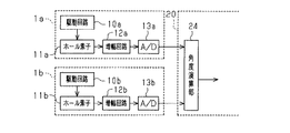
図9は、このようなICチップ1a、1bの内部回路をブロック図として示したものであり、以下、同図9を併せ参照して、その電気的な構成、並びにその構成に基づく動作についてさらに説明する。なお、このような回転角度検出装置は、種々の電気的構成によって実現されるものであるが、ここではICチップ1a、1bの内部回路として特に現在実用されている回路を説明する。
FIG. 9 is a block diagram showing the internal circuits of
同図9に示されるように、ICチップ1a、1bにあって、上記ホール素子11a、11bは、駆動回路10a、10bからの定電流、若しくは定電圧によってそれぞれ駆動される。ここで、これらホール素子11a、11bは、先の図8(b)に示した通り、互いの磁気感知面が直交するかたちで設けられている。また、これらホール素子11a、11bに付与される磁気ベクトルMVの向き(角度)は、上記着磁ロータRT(クランク軸CS)の回転角度が直接反映されたものとなっている。このような構成により、同ホール素子11a、11bからは、上記クランク軸CSの回動に伴って、図10(a)に示される90°だけ位相のずれたsin波形電圧(ホール電圧)A、Bがそれらの出力として取り出されるようになる。こうした出力信号A、Bは、これらICチップ1a、1bにおいて、増幅回路12a、12b、さらにはA/D変換器13a、13bに順次に取り込まれる。そして、上記増幅回路12a、12bでは各々所望に増幅され、上記A/D変換器13a、13bでは各々所要の分解能にて量子化されて後に離散的な値(デジタル値)に変換される。こうして離散化された2つの出力信号A、Bは、上記クランク軸CSの角度情報として当該ICチップ1a、1bの出力端子から各々取り出され、次いで、例えば車載エンジンの燃料噴射等の制御を行う電子制御装置20内の角度演算部24に取り込まれる。そして通常は、この角度演算部24において、上記クランク軸CSの回動に対して直線的に変化する信号にデジタル補正(角度演算)されることで、この信号に基づいて同クランク軸CSの回転角度が検出されるようになる。
As shown in FIG. 9, in the
ちなみに、この角度演算部24においては、まず、上記着磁ロータRT(クランク軸CS)の回転角度をθとしたときの上記出力信号Aをsinθ、他方の出力信号Bをcosθとするとき、同回転角度θが「θ=tan−1(A/B)」として算出される。ただし、こうして算出される信号波形は、図10(b)に示されるように、「θ=90°」及び「θ=270°」の各角度位置においてその値が最小値まで立ち下がるものであり、その算出結果のみから上記クランク軸CSの回転角度を一義的に導き出すことは困難である。そこで、この角度演算部24では次に、上記離散化された2つの出力信号A、Bの値やそれらの大小関係に基づき、図10(b)に示される信号波形のうち、例えば「θ=0°〜90°」の角度範囲、及び「θ=90°〜270°」の角度範囲、及び「θ=270°〜360°」の角度範囲に所定のオフセット値を各々加減算するなどして、これを図10(c)に示される信号波形に変換する。これにより、上記クランク軸CSの1回転(0°〜360°)毎の回転角度θに対して固有の値を持つリニアな信号波形が得られるようになり、このリニア信号に基づいて同クランク軸CSの回転角度θをきめ細かく検出することができるようになる。
ところで、上述したような回転角度検出装置は、その配設環境が必ずしも望ましい環境にあるとは限らず、例えば周辺機器の稼働等によって外乱磁界が発生したような場合には、上記磁気ベクトルMVの大きさが変化することが懸念される。すなわち、上記磁気ベクトルMVの大きさがこうして変化するようなことがあると、同磁気ベクトルMVの上記ホール素子11a、11bに作用する各ベクトル成分もその大きさが変化する。このため、それらホール素子11a、11bによる出力信号A、Bの振幅値などにずれが生じ、ひいてはこうした出力信号A、Bの振幅値などのずれが上記検出される回転角度θの角度誤差として現われるようになる。
By the way, the rotation angle detection apparatus as described above is not necessarily in a desirable environment. For example, when a disturbance magnetic field is generated due to operation of a peripheral device, the magnetic vector MV There is concern that the size will change. That is, when the magnitude of the magnetic vector MV changes in this way, the magnitude of each vector component acting on the
一方、上述の角度演算(「θ=tan−1(A/B)」)には、このような角度誤差を低減せしめる一定の効果があることが発明者によって確認されてはいるものの、より信頼性の高い角度情報を得ることのできる回転角度検出装置の開発が望まれている。 On the other hand, although the above-described angle calculation (“θ = tan −1 (A / B)”) has been confirmed by the inventor to have a certain effect of reducing such an angle error, it is more reliable. Development of a rotation angle detection device capable of obtaining highly reliable angle information is desired.
なお、ホール素子を用いた回転角度検出装置に限らず、例えば磁気抵抗素子などの他の磁気感知素子を用いた回転角度検出装置であっても、磁気感知素子による出力信号の振幅値やオフセットにずれが生じたときにその検出精度が低下する傾向は概ね共通したものとなっている。 It should be noted that the rotation angle detection device using another magnetic sensing element such as a magnetoresistive element is not limited to the rotation angle detection device using the Hall element, but the amplitude value or offset of the output signal from the magnetic sensing element is not limited. The tendency for the detection accuracy to decrease when a deviation occurs is generally the same.
この発明は、こうした実情に鑑みてなされたものであり、その目的は、磁気感知素子による出力信号に基づき被検出回転体の回転角度を検出するにあたってその出力信号の振幅値やオフセット値にずれが生じた場合であれ、被検出回転体に対する検出精度をより好適に維持することのできる回転角度検出装置を提供することにある。 The present invention has been made in view of such circumstances, and its purpose is to detect a deviation in the amplitude value or offset value of the output signal when detecting the rotation angle of the detected rotating body based on the output signal from the magnetic sensing element. It is an object of the present invention to provide a rotation angle detection device that can maintain the detection accuracy of a detected rotating body more favorably even if it occurs.
こうした目的を達成するため、請求項1に記載の回転角度検出装置では、回転角度の検出対象とする回転軸の回動に伴って回動する磁石から発せられる磁気ベクトルの変化を90度だけ位相のずれた正弦波信号として感知すべく配置された2つの磁気感知素子を有するセンサ部と、前記回転軸の回転角度を「θ」、前記磁気感知素子の一方の出力信号Aを「A=sinθ」、前記磁気感知素子の他方の出力信号Bを「B=cosθ」とするとき、前記2つの磁気感知素子による出力信号を「θ=tan−1(A/B)」の演算式に基づいて前記回転軸の回動に対してリニアに変化するリニア信号に変換する信号処理部とを備え、該信号処理部から取り出される信号に基づいて前記回転軸の回転角度を検出する回転角度検出装置として、前記2つの磁気感知素子を磁気感知素子対とするとき、前記センサ部が、複数の磁気感知素子対を有し、前記信号処理部が、前記複数の磁気感知素子対による出力信号の別に前記リニア信号を得るとともにそれらリニア信号に対して角度誤差を吸収し得る操作を施すことによって算出される1つの信号を前記回転軸の回転角度情報として出力することとした。
In order to achieve such an object, in the rotation angle detection device according to
前述の通り、「θ=tan−1(A/B)」の演算式には、上記磁気感知素子による出力信号A、Bの振幅値やオフセット値にずれが生じた場合に現われる角度誤差を低減せしめる一定の効果がある。この点、上記構成では、上記複数の磁気感知素子対による出力信号の別にこのような「θ=tan−1(A/B)」を演算し、それによって得られる複数のリニア信号に対して角度誤差を吸収し得る操作を施すこととしたため、より信頼性の高い角度情報を得ることが可能となる。 As described above, the calculation formula “θ = tan −1 (A / B)” reduces the angular error that appears when the amplitude values and offset values of the output signals A and B from the magnetic sensing element are shifted. It has a certain effect. In this regard, in the above-described configuration, such “θ = tan −1 (A / B)” is calculated separately from the output signals from the plurality of magnetic sensing element pairs, and the angle with respect to the plurality of linear signals obtained thereby is calculated. Since the operation capable of absorbing the error is performed, more reliable angle information can be obtained.
また、発明者は、「θ=tan−1(A/B)」の演算式について、その角度誤差の低減効果が同式中の左辺の「θ」を基準とした位相に応じて異なることを見い出した。この点、請求項1に記載の回転角度検出装置において、請求項2に記載の回転角度検出装置では、まず、上記複数の磁気感知素子対を、上記回転軸の回動に伴う磁気ベクトルの変化を各々位相の異なる出力信号として感知すべく配置した。そして、このような位相の異なる出力信号の別に「θ=tan−1(A/B)」の演算式を各々実施した。そしてこの上で、こうしたリニア信号に対してそれらの位相関係を維持しつつ上記角度誤差を吸収し得る操作を施すこととした。このため、上記「θ=tan−1(A/B)」の演算式による上記角度誤差の低減効果をその広い角度範囲にわたって得ることが可能となる。
Further, the inventor has found that the effect of reducing the angle error of the arithmetic expression “θ = tan −1 (A / B)” varies depending on the phase based on “θ” on the left side of the expression. I found it. In this regard, in the rotation angle detection device according to
なお、請求項1または2に記載の回転角度検出装置において、前記角度誤差を吸収し得る操作としては、例えば請求項3に記載の角度検出装置によるように、
・前記複数の磁気感知素子対の出力信号の別に得られる前記リニア信号の平均値を得る平均値演算。
あるいは、請求項4に記載の回転角度検出装置によるように、
・前記複数の磁気感知素子対の出力信号の別に得られる前記リニア信号の比較を通じて一致数が多数を占めるリニア信号の1つを選択的に得る多数決演算。
等々、といった操作を採用することが考えられる。これらいずれの操作であっても、被検出回転体(回転軸)に対する検出精度をより好適に維持することができるようになる。ただし、請求項2に記載の回転角度検出装置において、上記請求項3に記載の回転角度検出装置を採用した場合には、特に上記「θ=tan−1(A/B)」の演算式による上記角度誤差の低減効果がその広い角度範囲にわたってより好適に得られるようになる。
In the rotation angle detection device according to
An average value calculation for obtaining an average value of the linear signals obtained separately from output signals of the plurality of magnetic sensing element pairs.
Alternatively, as in the rotation angle detection device according to claim 4,
A majority operation for selectively obtaining one of the linear signals having a large number of matches through comparison of the linear signals obtained separately from the output signals of the plurality of magnetic sensing element pairs.
It is conceivable to employ an operation such as, etc. In any of these operations, the detection accuracy for the detected rotating body (rotating shaft) can be more suitably maintained. However, in the rotation angle detection device according to claim 2, when the rotation angle detection device according to claim 3 is employed, the calculation formula of “θ = tan −1 (A / B)” is particularly used. The effect of reducing the angle error can be obtained more suitably over the wide angle range.
また、回転角度の検出対象とする回転軸の回動に伴って回動する磁石や、磁気感知素子については、基本的に任意である。ただし、請求項5に記載の回転角度検出装置によるように、前記磁石が、そのN極とS極とが分離着磁されるかたちで前記回転軸と一体に形成された円盤状の着磁ロータからなり、前記センサ部及び前記信号処理部が、1つの半導体チップとして集積回路化されてなり、前記磁気感知素子が、ホール効果に基づき半導体基板面に平行な磁気ベクトルを感知する縦型ホール素子からなるようにすれば、当該回転角度検出装置としての集積化(小型化)を容易に図ることができるようになる。また、半導体プロセスを通じて、各ホール素子や各ホール素子対の配置関係をより正確に設定することができるようになる。 Further, the magnet that rotates with the rotation of the rotation shaft that is the detection target of the rotation angle and the magnetic sensing element are basically arbitrary. However, as in the rotation angle detection device according to claim 5, the magnet is a disc-shaped magnetized rotor formed integrally with the rotating shaft in such a manner that the N pole and the S pole are separated and magnetized. A vertical Hall element in which the sensor unit and the signal processing unit are integrated as a single semiconductor chip, and the magnetic sensing element senses a magnetic vector parallel to the semiconductor substrate surface based on the Hall effect. In this way, integration (miniaturization) as the rotation angle detection device can be easily achieved. In addition, through the semiconductor process, it is possible to set the positional relationship between the Hall elements and the Hall element pairs more accurately.
なお、請求項1〜5のいずれか一項に記載の回転角度検出装置においては、請求項6に記載の回転角度検出装置によるように、前記センサ部は、前記複数の磁気感知素子対として、2つの磁気感知素子対、あるいは請求項7に記載の回転角度検出装置によるように、3つの磁気感知素子対を有するようにすることが実用上望ましい。
In the rotation angle detection device according to any one of
以下、この発明にかかる回転角度検出装置の一実施の形態について、図1〜図6を参照して詳細に説明する。
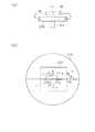
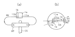
はじめに、図1を参照して、この回転角度検出装置の構成について詳述する。なお、図1(a)は、この装置の概略構成を示す側面図であり、図1(b)は、この装置の概略構成を示す平面図である。
Hereinafter, an embodiment of a rotation angle detection device according to the present invention will be described in detail with reference to FIGS.
First, the configuration of the rotation angle detection device will be described in detail with reference to FIG. FIG. 1A is a side view showing a schematic configuration of this apparatus, and FIG. 1B is a plan view showing the schematic configuration of this apparatus.
図1(a)に示されるように、この実施の形態にかかる回転角度検出装置も、
・回転角度の検出対象とするクランク軸300の回動に伴って回動する着磁ロータ(磁石)200から発せられる磁気ベクトルMVの変化を90度だけ位相のずれた正弦波信号(図10(a)参照)として感知する2つのホール素子を有するセンサ部111。
・クランク軸300の回転角度を「θ」、上記ホール素子の一方の出力信号Aを「A=sinθ」、上記ホール素子の他方の出力信号Bを「B=cosθ」とするとき、上記2つのホール素子による出力信号を「θ=tan−1(A/B)」の演算式に基づいて1つの信号(図10(c)参照)に変換する信号処理部。
等々、を備えて構成されている。ただしこの実施の形態では、ホール素子として、ホール効果に基づき半導体基板面に平行な磁気ベクトルMVを感知するいわゆる縦型ホール素子が採用されており、これによって上記センサ部111及び信号処理部は1つのICチップ100として集積回路化されている。
As shown in FIG. 1A, the rotation angle detection device according to this embodiment is also
A sine wave signal whose phase is shifted by 90 degrees from the change in the magnetic vector MV emitted from the magnetized rotor (magnet) 200 that rotates as the
When the rotation angle of the
And so on. However, in this embodiment, a so-called vertical Hall element that senses a magnetic vector MV parallel to the surface of the semiconductor substrate based on the Hall effect is employed as the Hall element, whereby the
ところで、前述のように、このような回転角度検出装置は、その配設環境が必ずしも望ましい環境にあるとは限らず、例えば周辺機器の稼働等によって外乱磁界が発生したような場合には、上記検出される回転角度に角度誤差が生じかねない。一方、「θ=tan−1(A/B)」の演算式には、このような角度誤差を低減せしめる一定の効果があることも前述した。 By the way, as described above, such a rotation angle detection device is not necessarily in a desirable environment. For example, when a disturbance magnetic field is generated due to the operation of a peripheral device or the like, An angular error may occur in the detected rotation angle. On the other hand, the arithmetic expression “θ = tan −1 (A / B)” also has a certain effect of reducing such an angle error as described above.
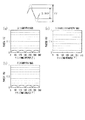
図2及び図3は、「θ=tan−1(A/B)」の演算式による上記角度誤差の低減効果を該演算式中の左辺の「θ」毎に示したものであり、次に、同図2及び図3を参照して同効果について説明する。なお、図2(a)〜(c)は、上記ホール素子による出力信号A、Bの振幅値に「1%」のずれが生じた場合に上記リニア信号に現われる角度誤差(%)を示したグラフである。また、図3(a)〜(c)は、上記ホール素子による出力信号A、Bのオフセット値に「1%」のずれが生じた場合に上記リニア信号に現われる角度誤差を示したグラフである。 FIG. 2 and FIG. 3 show the effect of reducing the angle error by the calculation formula “θ = tan −1 (A / B)” for each “θ” on the left side of the calculation formula. The same effect will be described with reference to FIGS. 2A to 2C show the angle error (%) appearing in the linear signal when a deviation of “1%” occurs in the amplitude values of the output signals A and B by the Hall element. It is a graph. FIGS. 3A to 3C are graphs showing angle errors appearing in the linear signal when a deviation of “1%” occurs in the offset values of the output signals A and B by the Hall element. .
すなわち、上記クランク軸300の回転角度θを「θ=tan−1(A/B)」の演算式に基づいて上記リニア信号として得るようにすれば、図2(a)〜(c)に示されるように、上記ホール素子による出力信号A、Bの振幅値に「1%」のずれが生じた場合であっても、その角度誤差は「0.1%」以下まで低減される。また同じく、図2(a)〜(c)に示されるように、上記ホール素子による出力信号A、Bのオフセット値に「1%」のずれが生じた場合であっても、その角度誤差は「0.2%強」以下まで低減される。
That is, if the rotation angle θ of the
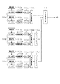
ただし、発明者は、図2(a)及び(b)に示されるように、上記ホール素子による出力信号A、Bの一方の振幅値のみにずれが生じた場合や、図3(a)〜(c)に示されるように、オフセット値にずれが生じたような場合には、その角度誤差の低減効果が上記演算式中の左辺の「θ」を基準とした位相に応じて異なることを見い出した。そこで、この実施の形態にかかる回転角度検出装置にあっては、上記2つのホール素子をホール素子対とするとき、上記センサ部111が、図1(b)に示されるように、上記クランク軸300の回動に伴う磁気ベクトルMVの変化を各々位相の異なる出力信号として感知すべく配置された3つのホール素子対111a〜111cを有するようにしている。また併せて、上記信号処理部が、これらホール素子対111a〜111cによる出力信号の別に上記リニア信号を得るとともに、同リニア信号の位相関係を維持しつつそれらの平均値を得る平均値演算を行うようにしている。
However, as shown in FIGS. 2 (a) and 2 (b), the inventor has a case where a deviation occurs only in the amplitude value of one of the output signals A and B by the Hall element, or FIGS. As shown in (c), when there is a deviation in the offset value, the effect of reducing the angle error varies depending on the phase with reference to “θ” on the left side in the above arithmetic expression. I found it. Therefore, in the rotation angle detection device according to this embodiment, when the two Hall elements are Hall element pairs, the
このような構成では、上記複数のホール素子対111a〜111cによる出力信号の別に得られる上記リニア信号の位相が上記複数のホール素子対111a〜111cの配置態様に応じて、ここでは「120°」だけ各々異なるようになる。このため、「θ=tan−1(A/B)」の演算式による角度誤差の低減効果も、このようなリニア信号に対して各々「120°」の位相だけずれて作用するようになる。そしてこの上で、このようなリニア信号の位相関係を維持しつつそれらの平均値を得る平均値演算が行われるため、上記「θ=tan−1(A/B)」の演算式による上記角度誤差の低減効果が平滑化され、同効果をその広い角度範囲にわたって好適に得ることができるようになる。 In such a configuration, the phase of the linear signal obtained separately from the output signals from the plurality of Hall element pairs 111a to 111c is “120 °” according to the arrangement mode of the plurality of Hall element pairs 111a to 111c. Only they will be different. For this reason, the effect of reducing the angle error by the arithmetic expression of “θ = tan −1 (A / B)” also acts on such a linear signal with a phase shift of “120 °”. Then, since the average value calculation for obtaining the average value is performed while maintaining the phase relationship of such linear signals, the angle according to the calculation formula of “θ = tan −1 (A / B)” is used. The effect of reducing the error is smoothed, and the same effect can be preferably obtained over the wide angular range.
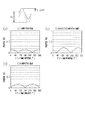
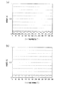
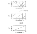
ここで、図4(a)は、上記角度誤差の低減効果が上記3つのリニア信号に対して各々「120°」の位相だけずれて作用する様子をグラフとして示したものである。なお、この図4(a)は、先の図2(a)に対応しており、上記ホール素子による出力信号Aの振幅値のみに「1%」のずれが生じた場合を想定している。また、同図4(a)中、実線がホール素子対111aから得られる信号に対応しており、2点鎖線がホール素子対111bから得られる信号に対応しており、1点鎖線がホール素子対111cから得られる信号に対応している。これに対し、図4(b)は、それらリニア信号を平均化した結果、該平均化信号に現われる角度誤差を上記検出される回転角度θ毎に示したものである。これら図4(a)及び(b)からも明らかなように、回転角度検出装置としての上記構成によれば、上記「θ=tan−1(A/B)」の演算式による上記角度誤差の低減効果がその広い角度範囲にわたって好適に得られた結果、上記リニア信号に現われる角度誤差が「0.07%弱」程度まで低減されていることがわかる。
Here, FIG. 4A is a graph showing how the effect of reducing the angle error acts on the three linear signals with a phase shift of “120 °”. FIG. 4A corresponds to FIG. 2A, and assumes a case where a deviation of “1%” occurs only in the amplitude value of the output signal A by the Hall element. . In FIG. 4A, the solid line corresponds to the signal obtained from the
図5は、このようなICチップ100を実現するための内部回路についてその一例を示したブロック図である。以下、同図5を併せ参照して、その電気的な構成、並びにその構成に基づく動作についてさらに説明する。
FIG. 5 is a block diagram showing an example of an internal circuit for realizing such an
同図5に示されるように、このICチップ100にあって、上記ホール素子対111aは、駆動回路110a、110bからの定電流、若しくは定電圧によってそれぞれ駆動される2つのホール素子からなる。ここで上述したが、同ホール素子対111aは、図6(a)に併せて示されるように、それら2つのホール素子の感知面が直交するかたちで設けられている。また、同ホール素子対111aに付与される磁気ベクトルMVの向き(角度)は、上記クランク軸300の回転角度θが直接反映されたものとなっている。このような構成により、同ホール素子対111aからは、上記クランク軸300の回動に伴って、図6(b)に示される90°だけ位相のずれたsin波形電圧(ホール電圧)A、Bがそれらの出力として取り出されるようになる。こうした出力信号A、Bは、このICチップ100において、信号処理部の一部を構成する増幅回路112a、112b、さらにはA/D変換器113a、113bに順次に取り込まれる。そして、上記増幅回路112a、112bでは各々所望に増幅され、上記A/D変換器113a、113bでは各々所要の分解能にて量子化されて後に離散的な値(デジタル値)に変換される。そして、こうして離散化された2つの出力信号A、Bは、次いで、角度演算部114abに各々取り込まれ、この角度演算部114abにおいて「θ=tan−1(A/B)」の演算式の下に、上記クランク軸300の回動に対してリニアに変化する図6(c)に示されるリニア信号Xに変換される。そして後述するが、このリニア信号Xが、平均値演算部116に取り込まれ、この平均値演算部116において、後述のリニア信号Y、Zとの平均値が算出される。
As shown in FIG. 5, in the
一方、上記ホール素子対111bやホール素子対111cも、駆動回路110c、110dあるいは駆動回路110e、110fからの定電流、若しくは定電圧によってそれぞれ駆動される2つの縦型ホール素子からなり、これら2つの縦型ホール素子の感知面が直交するかたちで設けられている。また、ホール素子対111bによる出力信号A、Bや、ホール素子対111cによる出力信号A、Bが、上記信号処理部に各々取り込まれて、
・増幅回路112c、112d、若しくは増幅回路112e、112fにおいて各々所望に増幅されること。
・A/D変換器113c、113d、若しくはA/D変換器113e、113fにおいて各々所要の分解能にて量子化されて後に離散的な値(デジタル値)に変換されること。
・角度演算部114cd、若しくは角度演算部114efにおいて「θ=tan−1(A/B)」の演算式の下に、上記クランク軸300の回動に対してリニアに変化するリニア信号Y、Zに変換されること。
等々、といった処理が順次に行われる点についても、上記ホール素子対111aとほぼ同様である。ただし、図6(d)、(h)に、先の図6(a)と比較して示すように、これらホール素子対111b、111cは、このICチップ100において、上記ホール素子対111aに対して時計回りに「120°」、「240°」だけ傾いて各々実装(配置)されている。このため、同ホール素子対111b、111cからの出力信号は、図6(e)、(i)に、先の図6(b)と比較して示すように、上記クランク軸300の回動に対し、上記ホール素子対111aによる出力信号よりも「120°」、「240°」だけ位相が遅れて変化する。さらには、図6(f)、(j)に、先の図6(c)と比較して示すように、上記角度演算部114cd、114efから取り出されるリニア信号Y、Zも、上記角度演算部114abから取り出されるリニア信号Xよりも「120°」、「240°」だけ遅れた位相関係となる。したがって、このような3つのリニア信号X〜Zの位相関係を維持しつつそれらの平均値を得るようにすることで、上記「θ=tan−1(A/B)」の演算式による上記角度誤差の低減効果を平滑化させることができるようになる。
On the other hand, the
The
The A /
The linear signals Y and Z that change linearly with respect to the rotation of the
The process is sequentially performed in a similar manner to the
ちなみに、この実施の形態では、図5に示されるように、このような平均値演算に先立って、上記3つのリニア信号X〜Zのうち、リニア信号Y、Zは、出力値調整部115cd、115efにまずは取り込まれる。そして、これらリニア信号Y、Zは、この出力値調整部115cd、115efにおいて、上記クランク軸300の回転角度に対して上記リニア信号Xとほぼ同一の出力値となる信号、具体的には、図6(g)、(k)に示されるリニア信号Y’、Z’に各々変換される。ただしこの際、リニア信号X〜Zの位相関係(「120°」ずつの位相ずれ)は維持され、例えば所定のオフセット値の加減演算のみによってこの信号変換(出力値調整)が行われる。そして、こうして得られる3つのリニア信号X、Y’、Z’が、平均値演算部116に取り込まれ、この平均値演算部116においてそれらの平均値を得る平均値演算が行われる。
Incidentally, in this embodiment, as shown in FIG. 5, prior to such average value calculation, among the three linear signals X to Z, linear signals Y and Z are output value adjustment unit 115 cd, 115ef is first taken in. The linear signals Y and Z are signals that have substantially the same output value as the linear signal X with respect to the rotation angle of the
以上説明したように、この実施の形態にかかる回転角度検出装置によれば、以下に記載するような優れた効果が得られるようになる。
(1)センサ部111が、上記クランク軸300の回動に伴う磁気ベクトルMVの変化を各々位相の異なる出力信号として感知すべく配置された3つのホール素子対111a〜111cを有することとした。また併せて、信号処理部が、上記複数のホール素子対111a〜111cによる出力信号の別にリニア信号X〜Zを得るとともに、同リニア信号の位相関係を維持しつつそれらの平均値を得る平均値演算を行うようにした。このため、「θ=tan−1(A/B)」の演算式による上記角度誤差の低減効果が平滑化され、同効果をその広い角度範囲にわたって好適に得ることができるようになる。
As described above, according to the rotation angle detection device of this embodiment, the following excellent effects can be obtained.
(1) The
(2)ホール素子として、ホール効果に基づき半導体基板面に平行な磁気ベクトルMVを感知するいわゆる縦型ホール素子を採用し、上記センサ部111及び信号処理部を1つのICチップ100として集積回路化した。このため、当該回転角度検出装置としての小型化が期待できる。また、互いに90度の関係をもって配されるホール素子や、120度の関係をもって配されるホール素子対111a〜111bを半導体基板中に正確に形成することができるようになる。
(2) A so-called vertical Hall element that senses a magnetic vector MV parallel to the surface of the semiconductor substrate based on the Hall effect is adopted as the Hall element, and the
なお、上記実施の形態は、以下のように変更して実施することもできる。
・上記実施の形態のICチップ100を実現するための内部回路の構成は任意である。例えば、上記実施の形態では、上記リニア信号Xを基準として、上記リニア信号Y、Zをリニア信号Y’、Z’に各々出力値調整することとした。ただし、リニア信号Yを基準として上記リニア信号X、Zの出力値調整を行うようにしてもよいし、リニア信号Zを基準として上記リニア信号X、Yの出力値調整を行うようにしてもよい。また、全てのリニア信号X〜Zの出力値調整を行うようにしてもよい。あるいは、3つのリニア信号X〜Yの平均値を演算した後にその平均化信号の出力値を調整するようにしてもよい。また、「θ=tan−1(A/B)」の演算式による上記角度誤差の低減効果を平滑化するといった効果を得る上では、こうした出力値調整については必ずしも行わなくてもよい。
In addition, the said embodiment can also be changed and implemented as follows.
The configuration of the internal circuit for realizing the
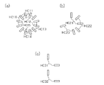
・上記実施の形態では、ホール素子対111a〜111cを備えることとしたが、図7(a)に示されるように、2つ以上のホール素子対を各々傾けて配置するものであればよい。なお、図7(a)は、6つのホール素子対HC11〜HC16を各々60°ずつ傾けて配置した場合を想定している。すなわちこの場合、これらホール素子対HC11〜HC16の別に得られる上記リニア信号の位相は各々60°ずつ異なるようになる。したがってこの場合であれ、それらリニア信号の位相関係を維持しつつ、それらの平均値を得るようにすれば、上記(1)の効果を得ることはできる。 In the above embodiment, the Hall element pairs 111a to 111c are provided. However, as shown in FIG. 7A, any two or more Hall element pairs may be disposed so as to be inclined. FIG. 7A assumes a case where the six Hall element pairs HC11 to HC16 are arranged so as to be inclined by 60 °. That is, in this case, the phases of the linear signals obtained separately for the Hall element pairs HC11 to HC16 are different from each other by 60 °. Therefore, even in this case, if the average value is obtained while maintaining the phase relationship between the linear signals, the effect (1) can be obtained.
・3つ以上のホール素子対を備える場合において、各ホール素子対の角度差は各々異なっていてもよい。例えば、図7(b)に示されるように、ホール素子対HC21及びHC22の角度差を「45°」に設定するとともに、ホール素子対HC22及びHC23の角度差を「105°」に設定するようにしてもよい。 In the case where three or more Hall element pairs are provided, the angular difference of each Hall element pair may be different. For example, as shown in FIG. 7B, the angle difference between the Hall element pair HC21 and HC22 is set to “45 °”, and the angle difference between the Hall element pair HC22 and HC23 is set to “105 °”. It may be.
・出力信号の位相をデジタル補正して互いに異ならしめることを条件に、図7(c)に示されるように、ホール素子対HC31、HC32を平行に配置してもよい。上記ホール素子対としては、要は、クランク軸300の回動に伴う磁気ベクトルMVの変化を各々位相の異なる出力信号として感知すべく配置されるものであればよい。
As shown in FIG. 7C, the Hall element pairs HC31 and HC32 may be arranged in parallel as long as the phase of the output signal is digitally corrected to be different from each other. The Hall element pair may be any element as long as it is arranged to detect a change in the magnetic vector MV accompanying the rotation of the
・上記平均値演算部116による平均値演算に際し、該平均値演算部116に取り込まれるリニア信号の重み付けを行うようにしてもよい。そしてこの際、該リニア信号の重み付けを上記クランク軸300の回転角度に応じて行うようにすれば、上記「θ=tan−1(A/B)」の演算式による上記角度誤差の低減効果をその広い角度範囲にわたってより好適に得ることが可能となる。
In the mean value calculation by the mean
・上記平均値演算部116に代えて、取り込まれるリニア信号の比較を通じて一致数が多数を占めるリニア信号の1つを選択的に出力する多数決演算部を採用するようにしてもよい。この場合であれ、上記「θ=tan−1(A/B)」の演算式による上記角度誤差の低減効果は平滑化され、リニア信号の角度誤差は吸収され得る。
Instead of the average
・「θ=tan−1(A/B)」の演算式には、ホール素子による出力信号A、Bの振幅値やオフセット値にずれが生じた場合に現われる角度誤差を低減せしめる一定の効果がある。したがって、複数のホール素子対による出力信号の別にこのような「θ=tan−1(A/B)」を演算し、それによって得られる複数のリニア信号に対して角度誤差を吸収し得る操作を施すようにしさえすれば、少なくともより信頼性の高い角度情報を得ることは可能になる。 The arithmetic expression “θ = tan −1 (A / B)” has a certain effect of reducing the angle error that appears when the amplitude values and offset values of the output signals A and B by the Hall element are shifted. is there. Therefore, an operation capable of calculating such “θ = tan −1 (A / B)” separately from the output signals from the plurality of Hall element pairs and absorbing the angle error with respect to the plurality of linear signals obtained thereby. As long as it is applied, at least more reliable angle information can be obtained.
・上記ホール素子として、ホール効果に基づき半導体基板面に垂直な磁気ベクトルを感知する横型ホール素子を採用してもよい。ただしこの場合、回転角度検出装置としての集積化は困難となる。 As the Hall element, a lateral Hall element that senses a magnetic vector perpendicular to the semiconductor substrate surface based on the Hall effect may be employed. However, in this case, integration as a rotation angle detection device becomes difficult.
・上記ホール素子対は複数であればよく、その数は任意である。
・上記ホール素子に代えて、磁気抵抗素子(MRE)を採用してもよい。要は、磁気ベクトルの変化を感知する磁気感知素子であればよい。
The number of the Hall element pairs may be plural, and the number is arbitrary.
A magnetoresistive element (MRE) may be employed instead of the Hall element. In short, any magnetic sensing element that senses changes in the magnetic vector may be used.
・磁石として着磁ロータ200を採用したが、回転角度の検出対象とする回転軸の回動に伴って回動する磁石であればよい。また、電磁石であってもよい。
・クランク軸の回転角度のほか、スロットルバルブの開度量など、各種回転体の回転角度を検出対象としてもよい。また、変位量を回転角度に変換可能なものであれば、回転体以外の物体を被検出回転体として採用することも可能である。
-Although the
-In addition to the rotation angle of the crankshaft, the rotation angle of various rotating bodies such as the opening amount of the throttle valve may be detected. Further, an object other than the rotating body can be adopted as the detected rotating body as long as the displacement amount can be converted into the rotation angle.
100…ICチップ、110a〜110f…駆動回路、111a〜111c…ホール素子対、112a〜112f…増幅回路、113a〜113f…A/D変換器、114ab、114cd、114ef…角度演算部、115cd、115ef…出力値調整部、116…平均値演算部、200…磁石、300…クランク軸。
DESCRIPTION OF
Claims (7)
前記2つの磁気感知素子を磁気感知素子対とするとき、前記センサ部は、複数の磁気感知素子対を有し、前記信号処理部は、前記複数の磁気感知素子対による出力信号の別に前記リニア信号を得るとともにそれらリニア信号に対して角度誤差を吸収し得る操作を施すことによって算出される1つの信号を前記回転軸の回転角度情報として出力する
ことを特徴とする回転角度検出装置。 Two magnetic sensing elements arranged to sense a change in magnetic vector emitted from a magnet that rotates as the rotation axis to be detected as a rotation angle is detected as a sine wave signal that is 90 degrees out of phase. The rotation angle of the rotating shaft is “θ”, one output signal A of the magnetic sensing element is “A = sin θ”, and the other output signal B of the magnetic sensing element is “B = cos θ”. A signal for converting the output signals from the two magnetic sensing elements into a linear signal that changes linearly with respect to the rotation of the rotating shaft based on an arithmetic expression of “θ = tan −1 (A / B)”. A rotation angle detecting device for detecting a rotation angle of the rotation shaft based on a signal extracted from the signal processing unit,
When the two magnetic sensing elements are magnetic sensing element pairs, the sensor unit includes a plurality of magnetic sensing element pairs, and the signal processing unit is configured to output the linear signal separately from output signals from the plurality of magnetic sensing element pairs. A rotation angle detection device that outputs a signal as rotation angle information of the rotation shaft by obtaining a signal and performing an operation that can absorb an angle error on the linear signal.
請求項1に記載の回転角度検出装置。 The plurality of magnetic sensing element pairs are arranged so as to sense a change in magnetic vector accompanying rotation of the rotating shaft as an output signal having a different phase, and the signal processing unit is obtained separately from the output signal. The rotation angle detection device according to claim 1, wherein an operation capable of absorbing the angle error is performed on the linear signals while maintaining their phase relationship.
請求項1または2に記載の回転角度検出装置。 The rotation angle detection device according to claim 1, wherein the operation capable of absorbing the angle error is an average value calculation for obtaining an average value of the linear signals obtained separately from output signals of the plurality of magnetic sensing element pairs.
請求項1または2に記載の回転角度検出装置。 The operation that can absorb the angular error is a majority operation that selectively obtains one of the linear signals that occupies a large number of matches through comparison of the linear signals obtained separately for the output signals of the plurality of magnetic sensing element pairs. The rotation angle detection device according to claim 1 or 2.
請求項1〜4のいずれか一項に記載の回転角度検出装置。 The magnet is formed of a disk-shaped magnetized rotor integrally formed with the rotating shaft in such a manner that the N pole and the S pole are separated and magnetized, and the sensor unit and the signal processing unit are one semiconductor. 5. The rotation according to claim 1, wherein the magnetic sensing element includes a vertical Hall element that senses a magnetic vector parallel to the semiconductor substrate surface based on a Hall effect. Angle detection device.
請求項1〜5のいずれか一項に記載の回転角度検出装置。 The sensor unit has two magnetic sensing element pairs as the plurality of magnetic sensing element pairs.
The rotation angle detection apparatus as described in any one of Claims 1-5.
請求項1〜5のいずれか一項に記載の回転角度検出装置。 The rotation angle detection device according to claim 1, wherein the sensor unit includes three magnetic sensing element pairs as the plurality of magnetic sensing element pairs.
Priority Applications (1)
| Application Number | Priority Date | Filing Date | Title |
|---|---|---|---|
| JP2005354009A JP2007155618A (en) | 2005-12-07 | 2005-12-07 | Rotation angle detection device |
Applications Claiming Priority (1)
| Application Number | Priority Date | Filing Date | Title |
|---|---|---|---|
| JP2005354009A JP2007155618A (en) | 2005-12-07 | 2005-12-07 | Rotation angle detection device |
Publications (1)
| Publication Number | Publication Date |
|---|---|
| JP2007155618A true JP2007155618A (en) | 2007-06-21 |
Family
ID=38240180
Family Applications (1)
| Application Number | Title | Priority Date | Filing Date |
|---|---|---|---|
| JP2005354009A Pending JP2007155618A (en) | 2005-12-07 | 2005-12-07 | Rotation angle detection device |
Country Status (1)
| Country | Link |
|---|---|
| JP (1) | JP2007155618A (en) |
Cited By (11)
| Publication number | Priority date | Publication date | Assignee | Title |
|---|---|---|---|---|
| JP2009098028A (en) * | 2007-10-17 | 2009-05-07 | Minebea Co Ltd | Resolver, measurement device, signal processing method and program |
| JP2010038765A (en) * | 2008-08-06 | 2010-02-18 | Tokai Rika Co Ltd | Rotation detector |
| JP2010038766A (en) * | 2008-08-06 | 2010-02-18 | Tokai Rika Co Ltd | Rotation detector |
| WO2011024731A1 (en) * | 2009-08-26 | 2011-03-03 | 株式会社ジェイテクト | Device for detecting angle of rotation |
| JP2012037466A (en) * | 2010-08-11 | 2012-02-23 | Tdk Corp | Rotation magnetic field sensor |
| JP2012037467A (en) * | 2010-08-11 | 2012-02-23 | Tdk Corp | Rotation magnetic sensor |
| JP2012047683A (en) * | 2010-08-30 | 2012-03-08 | Tdk Corp | Rotation magnetic field sensor |
| JP2012058202A (en) * | 2010-09-13 | 2012-03-22 | Tokai Rika Co Ltd | Rotational angle detection device |
| WO2014109190A1 (en) * | 2013-01-10 | 2014-07-17 | 村田機械株式会社 | Displacement sensor and displacement detection method |
| KR101904450B1 (en) * | 2011-04-20 | 2018-10-04 | 지케이엔 드라이브라인 뉴톤, 엘엘씨 | Power transfer unit |
| CN110023720A (en) * | 2016-09-13 | 2019-07-16 | Ntn-Snr轴承股份有限公司 | Determine the determination system of an at least rotational parameters for revolving member |
Citations (5)
| Publication number | Priority date | Publication date | Assignee | Title |
|---|---|---|---|---|
| JPH01251763A (en) * | 1988-03-31 | 1989-10-06 | Res Dev Corp Of Japan | Vertical hall element and integrated magnetic sensor |
| JPH09508214A (en) * | 1994-11-22 | 1997-08-19 | ローベルト ボツシユ ゲゼルシヤフト ミツト ベシユレンクテル ハフツング | Non-contact rotation angle detection device for rotatable members |
| JP2000065596A (en) * | 1998-08-20 | 2000-03-03 | Yaskawa Electric Corp | Magnetic encoder |
| JP2002506530A (en) * | 1998-04-18 | 2002-02-26 | ローベルト ボツシユ ゲゼルシヤフト ミツト ベシユレンクテル ハフツング | Angle sensor and method for angle measurement |
| JP2004507722A (en) * | 2000-08-22 | 2004-03-11 | ローベルト ボツシユ ゲゼルシヤフト ミツト ベシユレンクテル ハフツング | Angle measuring device and method |
-
2005
- 2005-12-07 JP JP2005354009A patent/JP2007155618A/en active Pending
Patent Citations (5)
| Publication number | Priority date | Publication date | Assignee | Title |
|---|---|---|---|---|
| JPH01251763A (en) * | 1988-03-31 | 1989-10-06 | Res Dev Corp Of Japan | Vertical hall element and integrated magnetic sensor |
| JPH09508214A (en) * | 1994-11-22 | 1997-08-19 | ローベルト ボツシユ ゲゼルシヤフト ミツト ベシユレンクテル ハフツング | Non-contact rotation angle detection device for rotatable members |
| JP2002506530A (en) * | 1998-04-18 | 2002-02-26 | ローベルト ボツシユ ゲゼルシヤフト ミツト ベシユレンクテル ハフツング | Angle sensor and method for angle measurement |
| JP2000065596A (en) * | 1998-08-20 | 2000-03-03 | Yaskawa Electric Corp | Magnetic encoder |
| JP2004507722A (en) * | 2000-08-22 | 2004-03-11 | ローベルト ボツシユ ゲゼルシヤフト ミツト ベシユレンクテル ハフツング | Angle measuring device and method |
Cited By (16)
| Publication number | Priority date | Publication date | Assignee | Title |
|---|---|---|---|---|
| JP2009098028A (en) * | 2007-10-17 | 2009-05-07 | Minebea Co Ltd | Resolver, measurement device, signal processing method and program |
| JP2010038765A (en) * | 2008-08-06 | 2010-02-18 | Tokai Rika Co Ltd | Rotation detector |
| JP2010038766A (en) * | 2008-08-06 | 2010-02-18 | Tokai Rika Co Ltd | Rotation detector |
| CN102575946A (en) * | 2009-08-26 | 2012-07-11 | 株式会社捷太格特 | Device for detecting angle of rotation |
| WO2011024731A1 (en) * | 2009-08-26 | 2011-03-03 | 株式会社ジェイテクト | Device for detecting angle of rotation |
| JP2012037466A (en) * | 2010-08-11 | 2012-02-23 | Tdk Corp | Rotation magnetic field sensor |
| JP2012037467A (en) * | 2010-08-11 | 2012-02-23 | Tdk Corp | Rotation magnetic sensor |
| JP2012047683A (en) * | 2010-08-30 | 2012-03-08 | Tdk Corp | Rotation magnetic field sensor |
| JP2012058202A (en) * | 2010-09-13 | 2012-03-22 | Tokai Rika Co Ltd | Rotational angle detection device |
| KR101904450B1 (en) * | 2011-04-20 | 2018-10-04 | 지케이엔 드라이브라인 뉴톤, 엘엘씨 | Power transfer unit |
| WO2014109190A1 (en) * | 2013-01-10 | 2014-07-17 | 村田機械株式会社 | Displacement sensor and displacement detection method |
| JP6015776B2 (en) * | 2013-01-10 | 2016-11-02 | 村田機械株式会社 | Displacement sensor and displacement detection method |
| US9772198B2 (en) | 2013-01-10 | 2017-09-26 | Murata Machinery, Ltd. | Displacement sensor and displacement detection method |
| TWI611163B (en) * | 2013-01-10 | 2018-01-11 | Murata Machinery Ltd | Displacement sensor and displacement detection method |
| CN110023720A (en) * | 2016-09-13 | 2019-07-16 | Ntn-Snr轴承股份有限公司 | Determine the determination system of an at least rotational parameters for revolving member |
| CN110023720B (en) * | 2016-09-13 | 2021-12-14 | Ntn-Snr轴承股份有限公司 | System for determining at least one rotation parameter of a rotating member |
Similar Documents
| Publication | Publication Date | Title |
|---|---|---|
| JP2007155618A (en) | Rotation angle detection device | |
| US9255817B2 (en) | Rotation-angle detection device, image processing apparatus, and rotation-angle detection method | |
| US7002339B2 (en) | Rotation angle detecting device | |
| JP3848670B1 (en) | Rotation angle detector | |
| JP5105200B2 (en) | Angle detection apparatus and angle detection method | |
| US20110246133A1 (en) | Rotator sensor | |
| US7671585B2 (en) | Rotation angle detecting device with a selecting means for selecting a pair of output signals of the magneto-sensing elements | |
| US9310448B2 (en) | Detection circuit, semiconductor integrated circuit device, magnetic field rotation angle detection device, and electronic device | |
| CN101243304B (en) | Rotation sensor and bearing with rotation sensing device | |
| US10508897B2 (en) | Magnet device and position sensing system | |
| JP2007139739A (en) | Device for detecting rotation angle | |
| WO2007077700A1 (en) | Rotation angle detector and bearing with rotation angle detector | |
| JP2011180001A (en) | Rotation sensor | |
| JPWO2018012272A1 (en) | Magnetic sensor and detection device using the same | |
| US9742425B2 (en) | Rotation detector and rotation detection method | |
| US11346688B2 (en) | Magnetic field sensors for detecting absolute position of multi-track targets | |
| JP5176208B2 (en) | Rotation angle detection method and rotation angle sensor | |
| JP4604992B2 (en) | Rotation angle detection device and rotation angle detection method | |
| JP4797581B2 (en) | Rotation angle detector | |
| JP5002917B2 (en) | Rotation angle detector | |
| US11056935B2 (en) | Rotation angle sensor system and semiconductor device | |
| US20220120590A1 (en) | Angle detection device | |
| JP2004264137A (en) | Method of determining correction value for noncontact rotation angle sensor and noncontact rotation angle sensor | |
| JP6291380B2 (en) | Non-contact rotation angle sensor | |
| JP2020106425A (en) | Magnetic sensor and detection method |
Legal Events
| Date | Code | Title | Description |
|---|---|---|---|
| A621 | Written request for application examination |
Free format text: JAPANESE INTERMEDIATE CODE: A621 Effective date: 20071220 |
|
| A131 | Notification of reasons for refusal |
Free format text: JAPANESE INTERMEDIATE CODE: A131 Effective date: 20100706 |
|
| A521 | Written amendment |
Free format text: JAPANESE INTERMEDIATE CODE: A523 Effective date: 20100827 |
|
| A131 | Notification of reasons for refusal |
Free format text: JAPANESE INTERMEDIATE CODE: A131 Effective date: 20110111 |
|
| A02 | Decision of refusal |
Free format text: JAPANESE INTERMEDIATE CODE: A02 Effective date: 20110809 |