WO2012150667A1 - Dispositif de station de base sans fil, dispositif de terminal mobile, système de communication sans fil et procédé de communication sans fil - Google Patents
Dispositif de station de base sans fil, dispositif de terminal mobile, système de communication sans fil et procédé de communication sans fil Download PDFInfo
- Publication number
- WO2012150667A1 WO2012150667A1 PCT/JP2012/053832 JP2012053832W WO2012150667A1 WO 2012150667 A1 WO2012150667 A1 WO 2012150667A1 JP 2012053832 W JP2012053832 W JP 2012053832W WO 2012150667 A1 WO2012150667 A1 WO 2012150667A1
- Authority
- WO
- WIPO (PCT)
- Prior art keywords
- downlink control
- control signal
- mobile terminal
- downlink
- signal
- Prior art date
Links
- 238000004891 communication Methods 0.000 title claims abstract description 32
- 238000000034 method Methods 0.000 title claims abstract description 16
- 230000005540 biological transmission Effects 0.000 claims abstract description 50
- 230000002776 aggregation Effects 0.000 claims description 55
- 238000004220 aggregation Methods 0.000 claims description 55
- 230000011664 signaling Effects 0.000 claims description 6
- 230000007274 generation of a signal involved in cell-cell signaling Effects 0.000 abstract description 4
- 238000012545 processing Methods 0.000 description 56
- 238000013507 mapping Methods 0.000 description 18
- 238000010586 diagram Methods 0.000 description 9
- 101150071746 Pbsn gene Proteins 0.000 description 5
- 239000013256 coordination polymer Substances 0.000 description 5
- 125000004122 cyclic group Chemical group 0.000 description 5
- 238000013468 resource allocation Methods 0.000 description 5
- 239000000969 carrier Substances 0.000 description 4
- 230000003044 adaptive effect Effects 0.000 description 3
- 238000012937 correction Methods 0.000 description 3
- 238000003780 insertion Methods 0.000 description 3
- 230000037431 insertion Effects 0.000 description 3
- 238000007726 management method Methods 0.000 description 3
- 238000005516 engineering process Methods 0.000 description 2
- 238000012986 modification Methods 0.000 description 2
- 230000004048 modification Effects 0.000 description 2
- 241001522296 Erithacus rubecula Species 0.000 description 1
- 101000741965 Homo sapiens Inactive tyrosine-protein kinase PRAG1 Proteins 0.000 description 1
- 102100038659 Inactive tyrosine-protein kinase PRAG1 Human genes 0.000 description 1
- 230000000694 effects Effects 0.000 description 1
- 239000000284 extract Substances 0.000 description 1
- 238000005562 fading Methods 0.000 description 1
- 230000002349 favourable effect Effects 0.000 description 1
- 230000006872 improvement Effects 0.000 description 1
- 230000007774 longterm Effects 0.000 description 1
- 230000007246 mechanism Effects 0.000 description 1
- 238000010295 mobile communication Methods 0.000 description 1
- 230000008569 process Effects 0.000 description 1
- 230000009467 reduction Effects 0.000 description 1
- 230000004044 response Effects 0.000 description 1
Images


Classifications
-
- H—ELECTRICITY
- H04—ELECTRIC COMMUNICATION TECHNIQUE
- H04J—MULTIPLEX COMMUNICATION
- H04J11/00—Orthogonal multiplex systems, e.g. using WALSH codes
- H04J11/0023—Interference mitigation or co-ordination
-
- H—ELECTRICITY
- H04—ELECTRIC COMMUNICATION TECHNIQUE
- H04L—TRANSMISSION OF DIGITAL INFORMATION, e.g. TELEGRAPHIC COMMUNICATION
- H04L5/00—Arrangements affording multiple use of the transmission path
- H04L5/0001—Arrangements for dividing the transmission path
- H04L5/0014—Three-dimensional division
- H04L5/0023—Time-frequency-space
-
- H—ELECTRICITY
- H04—ELECTRIC COMMUNICATION TECHNIQUE
- H04B—TRANSMISSION
- H04B7/00—Radio transmission systems, i.e. using radiation field
- H04B7/02—Diversity systems; Multi-antenna system, i.e. transmission or reception using multiple antennas
- H04B7/04—Diversity systems; Multi-antenna system, i.e. transmission or reception using multiple antennas using two or more spaced independent antennas
- H04B7/0413—MIMO systems
- H04B7/0452—Multi-user MIMO systems
-
- H—ELECTRICITY
- H04—ELECTRIC COMMUNICATION TECHNIQUE
- H04B—TRANSMISSION
- H04B7/00—Radio transmission systems, i.e. using radiation field
- H04B7/24—Radio transmission systems, i.e. using radiation field for communication between two or more posts
- H04B7/26—Radio transmission systems, i.e. using radiation field for communication between two or more posts at least one of which is mobile
- H04B7/2612—Arrangements for wireless medium access control, e.g. by allocating physical layer transmission capacity
-
- H—ELECTRICITY
- H04—ELECTRIC COMMUNICATION TECHNIQUE
- H04L—TRANSMISSION OF DIGITAL INFORMATION, e.g. TELEGRAPHIC COMMUNICATION
- H04L1/00—Arrangements for detecting or preventing errors in the information received
- H04L1/0001—Systems modifying transmission characteristics according to link quality, e.g. power backoff
- H04L1/0023—Systems modifying transmission characteristics according to link quality, e.g. power backoff characterised by the signalling
- H04L1/0027—Scheduling of signalling, e.g. occurrence thereof
-
- H—ELECTRICITY
- H04—ELECTRIC COMMUNICATION TECHNIQUE
- H04L—TRANSMISSION OF DIGITAL INFORMATION, e.g. TELEGRAPHIC COMMUNICATION
- H04L1/00—Arrangements for detecting or preventing errors in the information received
- H04L1/0001—Systems modifying transmission characteristics according to link quality, e.g. power backoff
- H04L1/0023—Systems modifying transmission characteristics according to link quality, e.g. power backoff characterised by the signalling
- H04L1/0028—Formatting
- H04L1/0031—Multiple signaling transmission
-
- H—ELECTRICITY
- H04—ELECTRIC COMMUNICATION TECHNIQUE
- H04L—TRANSMISSION OF DIGITAL INFORMATION, e.g. TELEGRAPHIC COMMUNICATION
- H04L5/00—Arrangements affording multiple use of the transmission path
- H04L5/003—Arrangements for allocating sub-channels of the transmission path
- H04L5/0053—Allocation of signaling, i.e. of overhead other than pilot signals
-
- H—ELECTRICITY
- H04—ELECTRIC COMMUNICATION TECHNIQUE
- H04W—WIRELESS COMMUNICATION NETWORKS
- H04W48/00—Access restriction; Network selection; Access point selection
- H04W48/08—Access restriction or access information delivery, e.g. discovery data delivery
- H04W48/12—Access restriction or access information delivery, e.g. discovery data delivery using downlink control channel
-
- H—ELECTRICITY
- H04—ELECTRIC COMMUNICATION TECHNIQUE
- H04W—WIRELESS COMMUNICATION NETWORKS
- H04W72/00—Local resource management
- H04W72/12—Wireless traffic scheduling
- H04W72/1263—Mapping of traffic onto schedule, e.g. scheduled allocation or multiplexing of flows
- H04W72/1273—Mapping of traffic onto schedule, e.g. scheduled allocation or multiplexing of flows of downlink data flows
-
- H—ELECTRICITY
- H04—ELECTRIC COMMUNICATION TECHNIQUE
- H04W—WIRELESS COMMUNICATION NETWORKS
- H04W72/00—Local resource management
- H04W72/20—Control channels or signalling for resource management
- H04W72/23—Control channels or signalling for resource management in the downlink direction of a wireless link, i.e. towards a terminal
-
- H—ELECTRICITY
- H04—ELECTRIC COMMUNICATION TECHNIQUE
- H04W—WIRELESS COMMUNICATION NETWORKS
- H04W74/00—Wireless channel access
- H04W74/04—Scheduled access
-
- H—ELECTRICITY
- H04—ELECTRIC COMMUNICATION TECHNIQUE
- H04L—TRANSMISSION OF DIGITAL INFORMATION, e.g. TELEGRAPHIC COMMUNICATION
- H04L27/00—Modulated-carrier systems
- H04L27/26—Systems using multi-frequency codes
- H04L27/2601—Multicarrier modulation systems
- H04L27/2626—Arrangements specific to the transmitter only
-
- H—ELECTRICITY
- H04—ELECTRIC COMMUNICATION TECHNIQUE
- H04L—TRANSMISSION OF DIGITAL INFORMATION, e.g. TELEGRAPHIC COMMUNICATION
- H04L27/00—Modulated-carrier systems
- H04L27/26—Systems using multi-frequency codes
- H04L27/2601—Multicarrier modulation systems
- H04L27/2647—Arrangements specific to the receiver only
-
- H—ELECTRICITY
- H04—ELECTRIC COMMUNICATION TECHNIQUE
- H04L—TRANSMISSION OF DIGITAL INFORMATION, e.g. TELEGRAPHIC COMMUNICATION
- H04L5/00—Arrangements affording multiple use of the transmission path
- H04L5/0001—Arrangements for dividing the transmission path
- H04L5/0003—Two-dimensional division
- H04L5/0005—Time-frequency
- H04L5/0007—Time-frequency the frequencies being orthogonal, e.g. OFDM(A), DMT
- H04L5/001—Time-frequency the frequencies being orthogonal, e.g. OFDM(A), DMT the frequencies being arranged in component carriers
Definitions
- the present invention relates to a radio base station apparatus, a mobile terminal apparatus, a radio communication system, and a radio communication method in a next generation radio communication system.
- LTE Long Term Evolution
- OFDMA Orthogonal Frequency Division Multiple Access
- SC-FDMA Single Carrier Frequency Division Multiple Access
- LTE-A LTE Advanced or LTE enhancement
- MIMO Multi-Input Multi-Input
- a MIMO system a plurality of transmission / reception antennas are prepared in a transceiver, and different transmission information sequences are transmitted simultaneously from different transmission antennas.
- MU-MIMO Multiple User MIMO
- HetNet Heterogeneous Network
- CoMP Coordinatd Multi-Point
- the present invention has been made in view of such points, and expands a downlink control channel to increase its capacity, and allows a radio base station to multiplex more downlink control information (DCI: Downlink Control Information).
- DCI Downlink Control Information
- An object is to provide a device, a mobile terminal device, a wireless communication system, and a wireless communication method.
- the radio base station apparatus of the present invention controls a signal generation unit that generates first and second downlink control signals addressed to a mobile terminal apparatus, and a first downlink control signal from the beginning of a subframe to a predetermined number of symbols.
- a first multiplexing unit that multiplexes in the region
- a second multiplexing unit that frequency-division-multiplexes the second downlink control signal into radio resources from the next symbol in the control region to the final symbol in the subframe, and multiplexes in the control region
- a transmitter that transmits the first downlink control signal and the second downlink control signal multiplexed on the radio resource.
- the mobile terminal apparatus performs frequency division into a first downlink control signal multiplexed in a control region from the beginning of a subframe to a predetermined number of symbols and a radio resource from the next symbol in the control region to the final symbol in the subframe.
- a receiving unit that receives the multiplexed second downlink control signal, channel estimation of the received first downlink control signal using a cell-specific reference signal, and the received second downlink control signal as a cell-specific or user
- a channel estimator that performs channel estimation using a unique reference signal and a demodulator that demodulates the first and second downlink control signals using channel estimation results are provided.
- the downlink control channel is expanded to increase its capacity and more DCI can be multiplexed.
- FIG. 1 is a schematic diagram of HetNet to which MU-MIMO is applied.
- the system shown in FIG. 1 includes a small base station apparatus RRH (Remote Radio Head) having a local cell in the cell of the base station apparatus eNB (eNodeB), and is configured in a hierarchical manner.
- RRH Remote Radio Head
- eNodeB base station apparatus
- UE User Equipment
- RRH Small Radio Head
- FIG. 2 is a diagram illustrating an example of a subframe in which downlink MU-MIMO transmission is performed.
- the downlink data signal for the mobile terminal apparatus UE and the downlink control information signal for receiving the downlink data are time-division multiplexed and transmitted.
- Predetermined OFDM symbols (1 to 3 OFDM symbols) from the top of the subframe are reserved as a radio resource region (PDCCH region) for a downlink control channel (PDCCH: Physical Downlink Control CHannel).
- the PDCCH region is composed of a maximum of 3 OFDM symbols from the top of the subframe, and the number of OFDM symbols dynamically changes for each subframe according to traffic information (for example, the number of connected users, etc.) (1 to 3 OFDM symbols). Is selected).
- a radio resource area (PDSCH area) for a downlink data channel (PDSCH: Physical Downlink Shared CHannel) is secured in radio resources after a predetermined number of symbols from the top of the subframe.
- DCI corresponding to each mobile terminal apparatus UE is assigned to the PDCCH region.
- DCI cannot be allocated to all mobile terminal apparatuses UE using only the PDCCH region including a maximum of three OFDM symbols from the top of the subframe.
- the DCI increases, the PDCCH region becomes insufficient, and the DCI allocation resources for the mobile terminal apparatuses UE # 5 and # 6 cannot be secured.
- a shortage of DCI allocation resources is assumed, and the influence on the throughput characteristics of MU-MIMO transmission is a problem.
- a frequency division multiplexing type PDCCH is set for radio resources after a predetermined number of symbols from the first symbol of a subframe, and a downlink control signal is arranged on the FDM type PDCCH.
- the downlink control signal and the downlink data signal are frequency division multiplexed and transmitted to the mobile terminal apparatus UE.
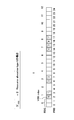
- FIG. 3 is a diagram illustrating a subframe configuration in which an existing PDCCH and an FDM type PDCCH are arranged.
- An existing PDCCH is arranged over the entire system band in the first number OFDM symbol (1 to 3 OFDM symbols) of the subframe, and an FDM type PDCCH is arranged in radio resources after the symbol in which the existing PDCCH is arranged.
- the frequency domain bandwidth of one FDM type PDCCH is the size of a radio resource scheduling unit, for example, one resource block (RB).
- the predetermined frequency area of the existing PDSCH area is expanded PDCCH.
- the extended PDCCH region can be demodulated using a user-specific DM-RS (DeModulation-Reference Signal) arranged in the existing PDSCH region.
- the DM-RS is defined as a demodulation reference signal for each UE and can perform beam forming individually for the UE, so that sufficient reception quality can be obtained. For this reason, even if it is UE near cell edge, if a communication environment is favorable, an aggregation level can be lowered
- FIG. 4 shows a case of resource allocation type 0 (Resource allocation type 0).
- resource allocation type 0 Resource allocation type 0
- Resource block allocation type 0 There are three different types of resource block allocation types (Resource allocation type 0, 1, 2).
- Resource block allocation types 0 and 1 support discontinuous frequency allocation in the frequency domain, and type 2 supports only continuous frequency allocation.
- Resource block allocation type 0 reduces the size of the bitmap by indicating not by individual resource blocks in the frequency domain but by groups of adjacent resource blocks.
- the size of the resource block group (RBG) is 2.
- the base station apparatus eNB notifies the mobile terminal apparatus UE of N VRB VRB sets as an enhanced PDCCH using higher layer signals.
- VRBs are numbered in order from the smaller PRB index (RBG index).
- the resource block of the extended PDCCH can be configured such that the downlink control signal is arranged in the first half slot (first slot) and the second half slot (second slot).
- a method (with cross interleaving) of assigning each user's downlink control signal in units of control channel elements (CCE) consisting of a plurality of resource element groups (REG), and a downlink control signal for each user is PRB.
- CCE control channel elements
- REG resource element groups
- the mobile terminal apparatus UE performs blind decoding in the search space specified by the CCE index, and in the case of without cross interleaving, performs blind decoding in the search space specified by the VRB index. Do.
- blind decoding in each format will be described.
- the base station apparatus eNB allocates a CCE composed of consecutive REGs in usable radio resources to the extended PDCCH.
- One CCE is composed of nine REGs.
- One REG is composed of four resource elements.
- REG corresponding to the number of CCEs according to the aggregation level of each mobile terminal apparatus UE is set with respect to extended PDCCH.
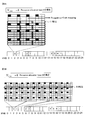
- the REG is arranged as shown in FIG. 5A.
- REGs constituting one CCE are continuously assigned in the frequency direction to the radio resources of the VRB constituting the extended PDCCH. As shown in FIG. 5B, nine REGs allocated in the frequency direction of successive VRB sets constitute one CCE. Note that, in a VRB radio resource, REG is assigned to a resource element assigned as a reference signal such as CRS except for the resource element. Further, the base station apparatus eNB assigns continuous CCEs to the extended PDCCH signal of each mobile terminal apparatus UE based on the aggregation level of each mobile terminal apparatus UE.
- the mobile terminal apparatus UE monitors a plurality of extended PDCCH candidates that may be set by higher layer signals. This is called blind decoding.
- the mobile terminal apparatus UE is not notified of the CCE to which the extended PDCCH signal addressed to the mobile terminal apparatus UE is allocated and the selected aggregation level. For this reason, the extended PDCCH is decoded in a round robin manner for all CCEs to which the extended PDCCH signal addressed to the own apparatus may be assigned.
- the base station apparatus eNB sets a search space for each mobile terminal apparatus UE in order to minimize the number of blind decoding attempts by the mobile terminal apparatus UE, and the mobile station apparatus UE addresses each mobile terminal apparatus UE within this search space.
- CCEs for extended PDCCH signals can be allocated. In this case, the mobile terminal apparatus UE attempts to decode the extended PDCCH within the corresponding search space.
- the base station apparatus eNB allocates DCI addressed to each mobile terminal apparatus UE to the extended PDCCH in units of PRBs. For example, the base station apparatus eNB determines an aggregation level indicating the number of VRBs to be continuously allocated based on the reception quality notified from each mobile terminal apparatus UE. Then, the number of VRBs corresponding to the aggregation level of each mobile terminal apparatus UE is allocated to the extended PDCCH as DCI radio resources for the mobile terminal apparatus UE.
- radio resources are allocated to the extended PDCCH as DCI radio resources for each mobile terminal apparatus UE in units of PRBs.
- a DM-RS which is a downlink reference signal for each user, is arranged in a radio resource in which the extended PDCCH may be arranged. Therefore, it is possible to demodulate the extended PDCCH using DM-RS. In this case, channel estimation in units of PRB is possible, and beam forming can be effectively formed for each mobile terminal apparatus UE.
- the mobile terminal apparatus UE monitors a plurality of extended PDCCH candidates that may be set by higher layer signals.
- the mobile terminal apparatus UE is not notified of the VRB of the enhanced PDCCH to which the DCI addressed to itself is assigned and the selected aggregation level. For this reason, decoding of the extended PDCCH is performed for all VRBs of the extended PDCCH signals to which the DCI addressed to the own apparatus may be assigned.
- the base station apparatus eNB sets a search space for each mobile terminal apparatus UE in order to minimize the number of blind decoding attempts by the mobile terminal apparatus UE, and the mobile station apparatus UE addresses each mobile terminal apparatus UE within this search space.
- VRBs for DCI can be allocated.
- the mobile terminal apparatus UE may perform DCI decoding within the corresponding search space (see FIG. 6).
- the mobile terminal apparatus UE can obtain the search space by the following equation (2) according to each aggregation level (in units of VRB).
- each aggregation level in units of VRB.
- the numbers of PDCCH candidates corresponding to each aggregation level ⁇ are 6, 6, 2, and 2, respectively.
- an aggregation level is 6, 6, 2, 2, here, of course, the number of candidates of an aggregation level and PDCCH is not restricted to this.
- the PRB index (RBG index) is assigned to the VRB.
- VRB indexes are numbered in order from the smallest (see FIG. 6).
- aggregation level 1 six search spaces are set in VRB # 0- # 5. At aggregation level 2, four search spaces are set in VRRB # 0 to # 7 in units of 2 VRB. At aggregation level 4, two search spaces are set in VRB # 0- # 7 in units of 4VRB. At aggregation level 8, one search space is set for VRB # 0 to # 7 in units of 8 VRB. Note that at aggregation levels 2 and 8, the search space overlaps due to a shortage of VRBs.
- the search space is blind-decoded according to the aggregation level, and the DCI assigned to the VRB is acquired.
- the DCI of each user is assigned in PRB units, and is blind-decoded in the search space defined by the VRB index.
- the extended PDCCH FDM type PDCCH
- the search space it is possible to suppress the number of blind decoding attempts in the mobile terminal apparatus UE.
- the second aspect of the present invention limits the types of aggregation levels and DCI formats that can be used in PDCCH and FDM type PDCCH. Thereby, it is possible to reduce the number of blind decoding and improve the characteristics according to the environment.
- the aggregation level is limited so that the aggregation level ⁇ differs between the PDCCH and the FDM type PDCCH.
- the aggregation level of PDCCH is limited to 4 or 8
- the aggregation level of FDM type PDCCH is limited to 1 or 2.
- limiting of the aggregation level with respect to PDCCH and FDM type PDCCH is not restrict
- the aggregation level may be limited so that the number of multiplexed users is maximized, or the aggregation level may be limited so that improvement of the characteristics of the cell edge user is prioritized.
- the mobile terminal apparatus UE is notified in advance of the restriction of the aggregation level for the PDCCH and the FDM type PDCCH.
- the mobile terminal apparatus UE is limited to the number of blind decodings according to the restricted aggregation level, so the total number of blind decodings can be reduced. .
- the DCI format type is limited so that the DCI format differs between the PDCCH and the FDM type PDCCH.
- the PDCCH is limited to transmission of DCI for downlink scheduling allocation (for example, DCI format 1A, 2 etc.)
- the FDM type PDCCH is for DCI for uplink grant (for example, DCI format 0, 4 etc.). Restrict to sending.
- the combination of DCI formats in PDCCH and FDM type PDCCH is not limited to this.
- the mobile terminal apparatus UE demodulates the DCI for downlink scheduling allocation in time, the mobile terminal apparatus UE starts demodulating the PDSCH immediately after decoding the PDCCH received earlier in time than the FDM type PDCCH. it can.
- the above-described restriction on the aggregation level or the restriction on the DCI format may be notified from the base station apparatus eNB to the mobile terminal apparatus UE using higher layer signaling, and the setting of the restriction may be dynamically switched. As a result, the system can be operated flexibly.
- the third aspect of the present invention limits the DCI type of each slot so that a plurality of DCIs of the same bit size are arranged in at least one slot in the first half slot and the second half slot of the PRB to which the FDM type PDCCH is allocated. To do. Thereby, since the frequency
- FIG. 7A is a schematic diagram showing a DCI arrangement in a case where R-PDCCH DCI assignment is directly adopted for the resource block of FDM type PDCCH proposed by the present inventors.
- FIG. 7B is an example in which the DCI format is limited so that a plurality of DCIs having the same bit size are arranged in the first half slot.
- the DCI format 0 for uplink grant which was placed in the latter half slot in FIG. 7A, is rearranged in the first half slot.
- the DCI format 0 has the same bit size as the DCI format 1A for downlink scheduling assignment allocated in the first half slot.
- the DCI formats 1A and 0 arranged in the first half slot have the same bit size in the mobile terminal apparatus UE, they can be decoded simultaneously by one blind decoding (up to 16 times).
- the remaining DCI format 2A arranged in the first half slot and the DCI format 4 arranged in the second half slot 16 blind decodings are tried, respectively. Therefore, the total number of blind decoding trials in the mobile terminal apparatus UE is 16 ⁇ 3 times (48 times). Therefore, since the number of blind decoding trials in the mobile terminal apparatus UE is reduced, the burden on the mobile terminal apparatus UE can be reduced.
- DCI format 1A and DCI format 0 are distinguished by processing the first 1 bit after performing blind decoding 16 times.
- the DCI format 1A arranged in the first half slot in FIG. 7A may be arranged in the second half slot.
- DCI formats 0 and 1A having the same bit size are arranged in the latter half slot.
- the total number of blind decoding trials in the mobile terminal apparatus UE is 16 ⁇ 3 times (48 times).
- the combination of DCI formats having the same message size in the resource block of the FDM type PDCCH is not limited to the above example.
- 4th aspect of this invention provides the search space structure at the time of applying FDM type PDCCH to cross-carrier scheduling (Cross-carrier scheduling).
- a basic frequency block corresponding to a system band up to LTE (Rel. 8) is referred to as a component carrier (CC), and a plurality of CCs are collected to widen the band. It has been agreed. Some CCs are subject to strong interference from other cells, while other CCs may cause a communication environment in which the influence of interference is small. Therefore, a mechanism for performing DCI allocation for a shared data channel (PDSCH or the like) transmitted by a CC having strong interference from other cells from another CC having a small influence of interference has been studied.
- PDSCH shared data channel
- sending a PDCCH of a CC that sends a PDSCH from a CC different from the CC is called cross-carrier scheduling.
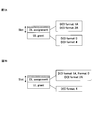
- FIG. 8 is a conceptual diagram when cross-carrier scheduling is applied.
- cross-carrier scheduling is applied in which a PDCCH of a CC (secondary cell) that transmits PDSCH is transmitted from a CC (primary cell) different from the CC (secondary cell).
- DCI-1 for assigning PDSCH or PUSCH of CC # 1 is assigned to PDCCH of CC # 1
- Each DCI is added with a 3-bit CIF (Carrier Indicator Field) indicating a CC to be scheduled.
- the mobile terminal apparatus UE can determine which CC is assigned to which CC based on the CIF value added to the demodulated DCI.
- CIF Carrier Indicator Field
- two search spaces of an FDM type PDCCH for PDSCH allocation of a primary cell and an FDM type PDCCH for PDSCH allocation of a secondary cell that are allocated to the same CC (primary cell) by cross carrier scheduling are continuous.
- the search space is configured as follows.
- FIG. 9 shows a state in which the search space for CC # 1 serving as the primary cell and the search space for CC # 2 serving as the secondary cell have a continuous configuration.
- the search space configuration in which the search spaces of the primary cell and the secondary cell are continuous can prevent the search spaces of the primary cell and the secondary cell from overlapping. Thereby, the probability that DCI which allocates PDSCH between different CCs is blocked can be reduced.
- the DCI allocation method to the FDM type PDCCH is without cross interleaving
- the DCI is allocated in units of PRBs, and therefore the search space start position in subframe n can be obtained by the following equation (4).
- the mobile terminal apparatus 10 and the base station apparatus 20 support LTE-A.
- the wireless communication system 1 includes a base station device 20 and a plurality of mobile terminal devices 10 that communicate with the base station device 20.
- the base station apparatus 20 is connected to the higher station apparatus 30, and the higher station apparatus 30 is connected to the core network 40.
- the base station devices 20 are connected to each other by wired connection or wireless connection.
- Each mobile terminal apparatus 10 can communicate with the base station apparatus 20 in the cells C1 and C2.
- the upper station device 30 includes, for example, an access gateway device, a radio network controller (RNC), a mobility management entity (MME), and the like, but is not limited thereto.
- RNC radio network controller
- MME mobility management entity
- Each mobile terminal apparatus 10 includes an LTE terminal and an LTE-A terminal, but the following description will be given as a mobile terminal apparatus unless otherwise specified. Further, for convenience of explanation, it is assumed that each mobile terminal device 10 performs wireless communication with the base station device 20, but more generally user devices including both mobile terminal devices and fixed terminal devices may be used.
- OFDMA Orthogonal Frequency Division Multiple Access
- SC-FDMA Single Carrier Frequency Division Multiple Access
- the uplink radio access scheme is not limited to this.
- OFDMA is a multi-carrier transmission scheme that performs communication by dividing a frequency band into a plurality of narrow frequency bands (subcarriers) and mapping data to each subcarrier.
- SC-FDMA is a single carrier transmission scheme that reduces interference between terminals by dividing a system band into bands each consisting of one resource block or a continuous resource block for each terminal, and a plurality of terminals using different bands. .
- the downlink communication channel includes a PDSCH shared by each mobile terminal apparatus 10, a downlink L1 / L2 control channel (PDCCH, PCFICH, PHICH), and an extended PDCCH.
- PDSCH downlink L1 / L2 control channel
- User data and higher control signals are transmitted by PDSCH.
- downlink control signals are multiplexed on radio resources from the beginning of a subframe to a predetermined number of OFDM symbols (1 to 3 OFDM symbols), and an extended PDCCH signal and a PDSCH signal are transmitted to radio resources after the predetermined number of OFDM symbols. Frequency division multiplexed.
- the extended PDCCH is used to support a lack of PDCCH capacity using a resource region to which the PDSCH is allocated.
- the upper control signal is a control expression that determines information related to the PRB position where the extended PDCCH is set (for example, RBG information), restrictions on the aggregation level for the PDCCH and the extended PDCCH, restrictions on the DCI format type, and a search space start position Information on parameters to be used can be included.
- the uplink control channel includes a PUSCH shared by each mobile terminal apparatus 10 and a PUCCH that is an uplink control channel. User data is transmitted by this PUSCH.
- Downlink radio quality information CQI: Channel Quality Indicator
- ACK / NACK signal retransmission response signal
- the base station apparatus 20 includes a plurality of transmission / reception antennas 201 for MIMO transmission, an amplifier unit 202, a transmission / reception unit (notification unit) 203, a baseband signal processing unit 204, a call processing unit 205, and a transmission path interface 206. And.
- the baseband signal processing unit 204 performs PDCP layer processing, user data division / combination, RLC layer transmission processing such as RLC (Radio Link Control) retransmission control transmission processing, MAC (Medium Access Control) retransmission control, for example, HARQ transmission processing, scheduling, transmission format selection, channel coding, Inverse Fast Fourier Transform (IFFT) processing, and precoding processing are performed.
- RLC Radio Link Control
- MAC Medium Access Control
- the baseband signal processing unit 204 notifies the mobile terminal device 10 of control information for wireless communication in the cell through the broadcast channel.
- the broadcast information for communication in the cell includes, for example, system bandwidth in uplink or downlink, root sequence identification information (Root Sequence Index) for generating a random access preamble signal in PRACH, and the like.
- Each transmitting / receiving unit 203 converts the baseband signal output by precoding from the baseband signal processing unit 204 for each antenna to a radio frequency band.
- the amplifier unit 202 amplifies the frequency-converted radio frequency signal and transmits the amplified signal using the transmission / reception antenna 201.
- radio frequency signals received by the respective transmitting / receiving antennas 201 are amplified by the amplifier sections 202 and frequency-converted by the respective transmitting / receiving sections 203. Is converted into a baseband signal and input to the baseband signal processing unit 204.
- the baseband signal processing unit 204 performs FFT processing, IDFT processing, error correction decoding, MAC retransmission control reception processing, RLC layer, and PDCP layer reception processing on user data included in the input baseband signal.
- the data is transferred to the higher station apparatus 30 via the transmission path interface 206.
- the call processing unit 205 performs call processing such as communication channel setting and release, state management of the base station apparatus 20, and radio resource management.
- the mobile terminal apparatus 10 includes a plurality of transmission / reception antennas 101 for MIMO transmission, an amplifier unit 102, a transmission / reception unit 103, a baseband signal processing unit 104, and an application unit 105.
- radio frequency signals received by a plurality of transmission / reception antennas 101 are respectively amplified by an amplifier unit 102, frequency-converted by a transmission / reception unit 103, and converted into a baseband signal.
- the baseband signal is subjected to FFT processing, error correction decoding, retransmission control reception processing, and the like by the baseband signal processing unit 104.
- downlink user data is transferred to the application unit 105.
- the application unit 105 performs processing related to layers higher than the physical layer and the MAC layer. Also, broadcast information in the downlink data is also transferred to the application unit 105.
- uplink user data is input from the application unit 105 to the baseband signal processing unit 104.
- transmission processing of retransmission control H-ARQ (Hybrid ARQ)
- channel coding precoding
- DFT processing IFFT processing
- IFFT processing IFFT processing
- the transmission / reception unit 103 converts the baseband signal output from the baseband signal processing unit 104 into a radio frequency band. Thereafter, the amplifier unit 102 amplifies the frequency-converted radio frequency signal and transmits the amplified signal using the transmission / reception antenna 101.
- FIG. 13 is a functional block diagram of baseband signal processing section 204 and some higher layers included in base station apparatus 20 according to the present embodiment. Mainly, functional blocks of transmission processing of baseband signal processing section 204 are shown. Show. FIG. 13 exemplifies a base station configuration that can support a maximum of M (CC # 0 to CC # M) component carriers. Transmission data for the mobile terminal apparatus 10 under the control of the base station apparatus 20 is transferred from the upper station apparatus 30 to the base station apparatus 20.
- M maximum of M
- the control information generation unit 300 generates higher control information for higher layer signaling (for example, RRC signaling) for each user.
- the upper control information can include a resource arrangement (PRB position) signal to which an extended PDCCH (FDM type PDCCH) can be mapped in advance.
- PRB position resource arrangement
- FDM type PDCCH extended PDCCH
- the data generation unit 301 outputs the transmission data transferred from the higher station apparatus 30 as user data for each user.
- the component carrier selection unit 302 selects a component carrier used for wireless communication with the mobile terminal device 10 for each user.
- the base station apparatus 20 notifies the mobile terminal apparatus 10 of addition / reduction of component carriers by RRC signaling, and receives an application completion message from the mobile terminal apparatus 10.
- the scheduling unit 310 controls the allocation of component carriers to the subordinate mobile terminal devices 10 according to the communication quality of the entire system band. Also, a specific component carrier (PCC) is determined from the component carriers selected for each mobile terminal device. In addition, scheduling section 310 controls resource allocation in each component carrier CC # 1-CC # M. Scheduling is performed by distinguishing between LTE terminal users and LTE-A terminal users. Scheduling section 310 receives transmission data and a retransmission instruction from higher station apparatus 30 and receives a channel estimation value and a CQI of a resource block from a receiving section that measures an uplink signal.
- PCC specific component carrier
- the scheduling unit 310 performs scheduling of the up / down control information and the up / down shared channel signal while referring to the input retransmission instruction, channel estimation value, and CQI.
- the propagation path in mobile communication varies depending on the frequency due to frequency selective fading. Therefore, the scheduling unit 310 instructs a resource block (mapping position) with good communication quality for each subframe for user data to each mobile terminal apparatus 10 (referred to as adaptive frequency scheduling).
- adaptive frequency scheduling the mobile terminal apparatus 10 with good channel quality is selected for each resource block. Therefore, the scheduling unit 310 indicates a resource block (mapping position) using the CQI for each resource block fed back from each mobile terminal apparatus 10.
- the scheduling unit 310 instructs a resource block (mapping position) with good communication quality for each subframe with respect to control information and the like transmitted on the extended PDCCH by adaptive frequency scheduling. For this reason, the scheduling unit 310 indicates a resource block (mapping position) using the CQI for each resource block fed back from each mobile terminal apparatus 10.
- the scheduling unit 310 controls the number of aggregations according to the propagation path status with the mobile terminal device 10.
- the number of CCE aggregation is controlled
- the number of CCE aggregation (with cross interleaving) or the number of VRB aggregations (without cross interleaving) is controlled.
- the number of aggregation is restrict
- the number of PDCCH aggregations is limited to 4, 8, and the number of extended PDCCH aggregations is limited to 1, 2.
- the number of CCE aggregation and the number of VRB aggregation will be increased.
- an MCS (coding rate, modulation scheme) that satisfies a predetermined block error rate with the allocated resource block is determined.
- Parameters satisfying the MCS (coding rate, modulation scheme) determined by the scheduling unit 310 are set in the channel coding units 303, 308, 312 and the modulation units 304, 309, 313.
- the baseband signal processing unit 204 includes a channel encoding unit 303, a modulation unit 304, and a mapping unit 305 corresponding to the maximum user multiplexing number N within one component carrier.
- the channel coding unit 303 channel-codes the downlink shared data channel (PDSCH) composed of user data (including some higher control signals) output from the data generation unit 301 for each user.
- Modulation section 304 modulates channel-coded user data for each user.
- the mapping unit 305 maps the modulated user data to radio resources.
- the baseband signal processing unit 204 includes generation units (downlink control information generation unit 306 and uplink control information generation unit 311) that generate control information using a predetermined DCI format from among a plurality of DCI formats.
- the plurality of DCI formats include a DCI format (for example, DCI format 0/4) including uplink grants and a DCI format (for example, DCI format 1A) including downlink scheduling allocation.
- Scheduling section 310 can limit the DCI format applied to PDCCH and enhanced PDCCH for downlink control information generation section 306 and uplink control information generation section 311.
- the PDCCH is limited to apply only the downlink DCI format (1A, 2 etc.), and the extended PDCCH is limited to apply only the uplink DCI format (0, 4 etc.).
- the scheduling unit 310 controls the extended PDCCH so that a plurality of DCI formats having the same bit size are arranged in the first half slot or the second half slot of the time domain.
- the downlink control information generation unit 306 generates downlink shared data channel control information for controlling PDSCH using a DCI format (for example, DCI format 1A) including downlink scheduling allocation. At this time, the downlink shared data channel control information is generated for each user. Further, the downlink shared data channel control information includes an identification field (CIF) that identifies an uplink serving cell to which the PDSCH is assigned. Scheduling section 310 determines the search space start position based on the CIF value when cross-carrier scheduling is applied. In the case of with cross interleaving, the scheduling unit 310 sets a search space based on the search space start position calculated by Expression (3), and in the case of without cross interleaving, the search space start position calculated by Expression (4). Set search space based on. In addition, the baseband signal processing unit 204 includes a downlink common channel control information generation unit 307 that generates downlink common control channel control information that is downlink control information common to users.
- a DCI format for example, DCI format 1A
- the uplink control information generation unit 311 generates uplink shared data channel control information for controlling PUSCH using a DCI format (for example, DCI format 0/4) containing uplink grants.
- the uplink shared data channel control information is generated for each user.
- the uplink shared data channel control information includes an identification field (CIF) for identifying an uplink serving cell to which a PUSCH is assigned.
- the baseband signal processing unit 204 channel-encodes the generated uplink shared data channel control information for each user, and modulates the channel-encoded uplink shared data channel control information for each user. And a modulation unit 313.
- the cell-specific reference signal generation unit 318 generates a cell-specific reference signal (CRS).
- the cell-specific reference signal (CRS) is multiplexed with the radio resource in the PDCCH region and transmitted.
- the user individual reference signal generation unit 320 generates a downlink demodulation reference signal (DM-RS: Downlink Modulation-Reference Signal).
- DM-RS Downlink demodulation reference signal
- a user-specific downlink demodulation reference signal (DM-RS) is multiplexed and transmitted on the radio resource in the PDSCH region.
- the control information modulated for each user by the modulation units 309 and 313 is multiplexed by the control channel multiplexing unit 314.
- the downlink control information for PDCCH is multiplexed into 1 to 3 OFDM symbols from the top of the subframe, and interleaved by interleave section 315.
- downlink control information for enhanced PDCCH (FRM type PDCCH) is frequency-division multiplexed to radio resources after a predetermined number of symbols in a subframe, and mapped to resource blocks (PRB) by mapping section 319.
- the mapping unit 319 performs mapping based on an instruction from the scheduling unit 310. Note that the mapping unit 319 may perform mapping by applying not cross interleaving but also with cross interleaving.
- the precoding weight multiplication unit 321 controls (shifts) the phase and / or amplitude of the transmission data mapped to the subcarrier and the demodulation reference signal (DM-RS) for each user for each of the plurality of antennas.
- the transmission data and the user-specific demodulation reference signal (DM-RS) shifted in phase and / or amplitude by the precoding weight multiplication unit 321 are output to the IFFT unit 316.
- the IFFT unit 316 receives control signals from the interleaving unit 315 and the mapping unit 318, and receives user data from the mapping unit 305.
- the IFFT unit 316 converts the downlink channel signal from a frequency domain signal to a time-series signal by performing inverse fast Fourier transform.
- the cyclic prefix insertion unit 317 inserts a cyclic prefix into the time-series signal of the downlink channel signal.
- the cyclic prefix functions as a guard interval for absorbing a difference in multipath propagation delay.
- the transmission data to which the cyclic prefix is added is sent to the transmission / reception unit 203.
- FIG. 14 is a functional block diagram of the baseband signal processing unit 104 included in the user terminal 10, and shows functional blocks of the LTE-A terminal that supports LTE-A.
- the CP is removed by the CP removal unit 401 from the downlink signal received from the radio base station apparatus 20 as reception data.
- the downlink signal from which the CP is removed is input to the FFT unit 402.
- the FFT unit 402 performs fast Fourier transform (FFT) on the downlink signal to convert it from a time domain signal to a frequency domain signal, and inputs it to the demapping unit 403.
- the demapping unit 403 demaps the downlink signal, and extracts multiplex control information, user data, and higher control signal in which a plurality of control information is multiplexed from the downlink signal. Note that the demapping process by the demapping unit 403 is performed based on a higher control signal input from the application unit 105.
- the multiplex control information output from the demapping unit 403 is deinterleaved by the deinterleaving unit 404. Note that an extended PDCCH signal that has not been interleaved may be input to control information demodulation section 405 without going through deinterleaving section 404.
- the baseband signal processing unit 104 includes a control information demodulation unit 405 that demodulates control information, a data demodulation unit 406 that demodulates downlink shared data, and a channel estimation unit 407.
- the control information demodulator 405 includes a common control channel control information demodulator 405a that demodulates downlink common control channel control information from the multiplex control information, and an uplink shared data channel that demodulates uplink shared data channel control information from the multiplex control information. And a downlink shared data channel control information demodulator 405c that demodulates downlink shared data channel control information from the multiplexed control information.
- the data demodulator 406 includes a downlink shared data demodulator 406a that demodulates user data and higher control signals, and a downlink common channel data demodulator 406b that demodulates downlink common channel data.
- the common control channel control information demodulator 405a receives common control channel control information, which is common control information for users through blind decoding processing, demodulation processing, channel decoding processing, and the like of the common search space of the downlink control channel (PDCCH). Take out.
- the common control channel control information includes downlink channel quality information (CQI), is input to the mapping unit 415, and is mapped as part of transmission data to the base station apparatus 20.
- CQI downlink channel quality information
- the uplink shared data channel control information demodulator 405b performs uplink shared data channel control information (for example, UL Grant) through blind decoding processing, demodulation processing, channel decoding processing, and the like of the user-specific search space of the downlink control channel (PDCCH). ).
- the demodulated uplink shared data channel control information is input to the mapping unit 415 and used for uplink shared data channel (PUSCH) control.
- the downlink shared data channel control information demodulating section 405c performs user-specific downlink shared data channel control information (for example, blind decoding processing, demodulation processing, channel decoding processing, etc.) for the user dedicated search space of the downlink control channel (PDCCH). , DL assignment).
- the demodulated downlink shared data channel control information is input to the downlink shared data demodulation unit 406, used for controlling the downlink shared data channel (PDSCH), and input to the downlink shared data demodulation unit 406a.
- the control information demodulating unit 405 demodulates the PCFICH from the head symbol of the subframe to identify the control area where the PDCCH is arranged, and demodulates the PDCCH from the identified control area.
- Control information demodulation section 405 demodulates the extended PDCCH frequency-division multiplexed on the radio resource (data area) from the next symbol in the control area to the final symbol in the subframe.
- the control information demodulating unit 405 calculates the search space start position using Equation (3) in the case of with cross interleaving, and searches specified based on the calculated search space start position. Blind decoding space. Further, in the case of without cross interleaving, the search space start position is calculated by Equation (4), and the search space is blind-decoded based on the calculated search space start position.
- blind decoding is performed in CCE units for extended PDCCH and PDCCH to which “with cross interleaving” is applied, and blind decoding is performed in VRB units to extended PDCCH and PDCCH to which “without cross interleaving” is applied.
- the control information demodulator 405 performs blind decoding according to each aggregation level restricted by the extended PDCCH and the PDCCH when the restriction information on the number of aggregations of the extended PDCCH and the PDCCH is notified. Also, when downlink DCI (format 1A, 2 etc.) is assigned to PDCCH and uplink DCI (format 0, 4 etc.) is assigned to extended PDCCH, downlink DCI is demodulated from PDCCH and uplink DCI from extended PDCCH. Is demodulated. For the extended PDCCH, when a plurality of DCI formats having the same bit size are arranged in the first half slot or the second half slot, the DCI formats having the same bit size are demodulated simultaneously by one blind decoding.
- the downlink shared data demodulator 406a acquires user data and higher control information based on the downlink shared data channel control information input from the downlink shared data channel control information demodulator 405c.
- the PRB position (VRB position) to which the extended PDCCH included in the higher control information can be mapped is output to the downlink shared data channel control information demodulation section 405c.
- the downlink common channel data demodulation unit 406b demodulates the downlink common channel data based on the uplink shared data channel control information input from the uplink shared data channel control information demodulation unit 405b.
- the channel estimation unit 407 performs channel estimation using a user-specific reference signal (DM-RS) or a cell-specific reference signal (CRS).
- DM-RS user-specific reference signal
- CRS cell-specific reference signal
- the baseband signal processing unit 104 includes a data generation unit 411, a channel encoding unit 412, a modulation unit 413, a DFT unit 414, a mapping unit 415, an IFFT unit 416, and a CP insertion unit 417 as functional blocks of a transmission processing system. Yes.
- the data generation unit 411 generates transmission data from the bit data input from the application unit 105.
- the channel coding unit 412 performs channel coding processing such as error correction on the transmission data, and the modulation unit 413 modulates the channel coded transmission data with QPSK or the like.
- the DFT unit 414 performs discrete Fourier transform on the modulated transmission data.
- Mapping section 415 maps each frequency component of the data symbol after DFT to a subcarrier position designated by base station apparatus 20.
- the IFFT unit 416 performs inverse fast Fourier transform on input data corresponding to the system band to convert it into time series data, and the CP insertion unit 417 inserts a cyclic prefix into the time series data at data delimiters.
Landscapes
- Engineering & Computer Science (AREA)
- Signal Processing (AREA)
- Computer Networks & Wireless Communication (AREA)
- Quality & Reliability (AREA)
- Computer Security & Cryptography (AREA)
- Mobile Radio Communication Systems (AREA)
Abstract
Priority Applications (7)
| Application Number | Priority Date | Filing Date | Title |
|---|---|---|---|
| KR1020137031042A KR101794099B1 (ko) | 2011-05-02 | 2012-02-17 | 무선기지국장치, 이동단말장치, 무선통신시스템 및 무선통신방법 |
| KR1020167002805A KR20160019972A (ko) | 2011-05-02 | 2012-02-17 | 무선기지국장치, 이동단말장치, 무선통신시스템 및 무선통신방법 |
| EP12779831.2A EP2706800B1 (fr) | 2011-05-02 | 2012-02-17 | Dispositif de station de base sans fil, dispositif de terminal mobile, système de communication sans fil et procédé de communication sans fil |
| CN201280021496.XA CN103503544B (zh) | 2011-05-02 | 2012-02-17 | 无线基站装置、移动终端装置、无线通信系统以及无线通信方法 |
| CA2834208A CA2834208C (fr) | 2011-05-02 | 2012-02-17 | Dispositif de station de base sans fil, dispositif de terminal mobile, systeme de communication sans fil et procede de communication sans fil |
| US14/114,478 US9420609B2 (en) | 2011-05-02 | 2012-02-17 | Radio base station apparatus, mobile terminal apparatus, radio communication system and radio communication method |
| US15/135,029 US9756633B2 (en) | 2011-05-02 | 2016-04-21 | Radio base station apparatus, mobile terminal apparatus, radio communication system and radio communication method |
Applications Claiming Priority (2)
| Application Number | Priority Date | Filing Date | Title |
|---|---|---|---|
| JP2011103223A JP5587824B2 (ja) | 2011-05-02 | 2011-05-02 | 無線基地局装置、移動端末装置、無線通信システムおよび無線通信方法 |
| JP2011-103223 | 2011-05-02 |
Related Child Applications (2)
| Application Number | Title | Priority Date | Filing Date |
|---|---|---|---|
| US14/114,478 A-371-Of-International US9420609B2 (en) | 2011-05-02 | 2012-02-17 | Radio base station apparatus, mobile terminal apparatus, radio communication system and radio communication method |
| US15/135,029 Continuation US9756633B2 (en) | 2011-05-02 | 2016-04-21 | Radio base station apparatus, mobile terminal apparatus, radio communication system and radio communication method |
Publications (1)
| Publication Number | Publication Date |
|---|---|
| WO2012150667A1 true WO2012150667A1 (fr) | 2012-11-08 |
Family
ID=47107858
Family Applications (1)
| Application Number | Title | Priority Date | Filing Date |
|---|---|---|---|
| PCT/JP2012/053832 WO2012150667A1 (fr) | 2011-05-02 | 2012-02-17 | Dispositif de station de base sans fil, dispositif de terminal mobile, système de communication sans fil et procédé de communication sans fil |
Country Status (9)
| Country | Link |
|---|---|
| US (2) | US9420609B2 (fr) |
| EP (2) | EP2706800B1 (fr) |
| JP (1) | JP5587824B2 (fr) |
| KR (2) | KR20160019972A (fr) |
| CN (2) | CN105846957B (fr) |
| CA (2) | CA2971335A1 (fr) |
| ES (1) | ES2611213T3 (fr) |
| PT (1) | PT2955970T (fr) |
| WO (1) | WO2012150667A1 (fr) |
Cited By (2)
| Publication number | Priority date | Publication date | Assignee | Title |
|---|---|---|---|---|
| CN105637959A (zh) * | 2013-10-31 | 2016-06-01 | 松下电器(美国)知识产权公司 | 无线通信方法、演进节点b和用户设备 |
| CN109392133A (zh) * | 2017-08-11 | 2019-02-26 | 华为技术有限公司 | 一种无线通信方法及装置 |
Families Citing this family (31)
| Publication number | Priority date | Publication date | Assignee | Title |
|---|---|---|---|---|
| PT3048753T (pt) * | 2011-05-03 | 2019-05-29 | Ericsson Telefon Ab L M | Monitorização de canal de controlo com base em área de pesquisa |
| WO2012150822A2 (fr) * | 2011-05-03 | 2012-11-08 | 엘지전자 주식회사 | Procédé de réception d'un signal de liaison descendante, dispositif utilisateur, procédé d'émission d'un signal de liaison descendante, et station de base associée |
| KR101510582B1 (ko) | 2011-06-15 | 2015-04-08 | 삼성전자주식회사 | 통신 시스템에서 물리 하향링크 제어 시그널링의 확장 |
| US9313747B2 (en) * | 2011-07-01 | 2016-04-12 | Intel Corporation | Structured codebook for uniform circular array (UCA) |
| AU2013235809B2 (en) | 2012-03-19 | 2017-01-05 | Telefonaktiebolaget L M Ericsson (Publ) | Aggregation of resources in enhanced control channels |
| EP3709557B1 (fr) * | 2012-05-09 | 2021-12-22 | Sun Patent Trust | Circuit integré pour la configuration d'espaces de rechereche dans des régions de type e-pdcch pour des porteuses composantes différentes |
| US9768926B2 (en) | 2013-03-04 | 2017-09-19 | Lg Electronics Inc. | Method and apparatus for receiving control information in wireless communication system |
| JP2014204254A (ja) * | 2013-04-04 | 2014-10-27 | シャープ株式会社 | 端末装置、基地局装置、無線通信システムおよび通信方法 |
| WO2014181430A1 (fr) * | 2013-05-09 | 2014-11-13 | 富士通株式会社 | Dispositif de station de base, dispositif de station mobile et procede de communication |
| CN104703212B (zh) * | 2013-12-06 | 2019-07-23 | 索尼公司 | 无线通信系统中的装置、无线通信系统和方法 |
| KR101807816B1 (ko) * | 2014-10-20 | 2017-12-11 | 한국전자통신연구원 | 분산 안테나 시스템에서 다중 사용자 다중 안테나 송수신을 위한 기지국의 통신 장치 및 통신 방법 |
| KR20160052982A (ko) * | 2014-10-29 | 2016-05-13 | 한국전자통신연구원 | 고속 이동 네트워크 환경에서의 신호 수신 방법 및 그 장치 |
| US10652768B2 (en) | 2015-04-20 | 2020-05-12 | Qualcomm Incorporated | Control channel based broadcast messaging |
| DE112015006893T5 (de) * | 2015-09-10 | 2018-05-24 | Intel IP Corporation | Evolved Node-B (eNB), Nutzerausrüstung (UE) und Verfahren zur flexiblen Duplex-Kommunikation |
| US10461908B2 (en) * | 2015-11-11 | 2019-10-29 | Qualcomm Incorporated | Techniques for providing channels in low latency LTE wireless communications |
| CN106817773B (zh) * | 2015-12-01 | 2019-07-19 | 展讯通信(上海)有限公司 | 用户终端调度方法及装置 |
| JP2019091957A (ja) * | 2016-03-30 | 2019-06-13 | シャープ株式会社 | 端末装置、基地局装置、通信方法、および、集積回路 |
| CA3004858A1 (fr) | 2016-03-31 | 2017-10-05 | Sony Corporation | Dispositif de terminal, dispositif de station de base, et procede de communication |
| US10356800B2 (en) * | 2016-05-09 | 2019-07-16 | Qualcomm Incorporated | Scalable numerology with symbol boundary alignment for uniform and non-uniform symbol duration in wireless communication |
| MX2019005155A (es) * | 2016-11-03 | 2019-06-20 | Guangdong Oppo Mobile Telecommunications Corp Ltd | Metodo de transmision de se?ales, dispositivo de terminal y dispositivo de red. |
| KR20180068677A (ko) * | 2016-12-14 | 2018-06-22 | 삼성전자주식회사 | 무선 통신 시스템에서 하향링크 제어채널의 송수신 방법 및 장치 |
| US11122600B2 (en) * | 2016-12-19 | 2021-09-14 | Ntt Docomo, Inc. | Terminals receiving downlink control signals and downlink data signals |
| MX2020001608A (es) * | 2017-08-10 | 2020-07-14 | Ntt Docomo Inc | Terminal de usuario y metodo de radiocomunicacion. |
| CN108093480B (zh) * | 2017-09-30 | 2024-02-13 | 中兴通讯股份有限公司 | 一种信号传输的方法及装置 |
| US10687324B2 (en) * | 2017-10-02 | 2020-06-16 | Telefonaktiebolaget Lm Ericsson (Publ) | PDCCH monitoring periodicity |
| CN115276936A (zh) | 2017-10-02 | 2022-11-01 | 瑞典爱立信有限公司 | 用于监控的方法和设备 |
| CN109673027B (zh) * | 2017-10-16 | 2023-01-10 | 中兴通讯股份有限公司 | 多集中单元cu融合方法、相应设备及系统 |
| CN111434162A (zh) * | 2017-11-16 | 2020-07-17 | 株式会社Ntt都科摩 | 用户终端以及无线通信方法 |
| WO2019138510A1 (fr) * | 2018-01-11 | 2019-07-18 | 株式会社Nttドコモ | Terminal utilisateur et procédé de communication sans fil |
| CN110167166B (zh) * | 2018-02-14 | 2022-12-27 | 上海朗帛通信技术有限公司 | 一种基站、用户设备中的用于无线通信的方法和装置 |
| KR20210132531A (ko) * | 2020-04-27 | 2021-11-04 | 삼성전자주식회사 | 무선 통신 시스템에서 제어 정보를 설정하는 방법 및 장치 |
Citations (1)
| Publication number | Priority date | Publication date | Assignee | Title |
|---|---|---|---|---|
| WO2010125794A1 (fr) * | 2009-04-27 | 2010-11-04 | パナソニック株式会社 | Dispositif de communication sans fil et procédé de communication sans fil |
Family Cites Families (9)
| Publication number | Priority date | Publication date | Assignee | Title |
|---|---|---|---|---|
| CN104270230B (zh) * | 2007-06-22 | 2018-01-02 | Tcl通讯科技控股有限公司 | 通信方法及移动终端 |
| EP2353327B1 (fr) * | 2008-11-04 | 2019-03-27 | Apple Inc. | Établissement de structure de commande de liaison descendante dans une première porteuse pour indiquer une information de commande dans une seconde porteuse différente |
| EP2424139A4 (fr) * | 2009-04-24 | 2016-05-18 | Lg Electronics Inc | Procédé et appareil pour transmettre et recevoir un signal de commande pour fusionner des porteuses lors d'une transmission |
| KR20110020708A (ko) * | 2009-08-24 | 2011-03-03 | 삼성전자주식회사 | Ofdm 시스템에서 셀간 간섭 조정을 위한 제어 채널 구성과 다중화 방법 및 장치 |
| US8433251B2 (en) * | 2009-09-28 | 2013-04-30 | Qualcomm Incorporated | Control information signaling |
| EP3731451B1 (fr) * | 2009-09-28 | 2023-01-25 | Samsung Electronics Co., Ltd. | Extension des canaux de commande de liaison descendante physique |
| EP2536047B1 (fr) * | 2010-02-09 | 2020-03-04 | LG Electronics Inc. | Procédé d'émission d'un signal montant dans un système de communication sans fil et dispositif correspondant |
| KR101684867B1 (ko) * | 2010-04-07 | 2016-12-09 | 삼성전자주식회사 | 공간 다중화 이득을 이용한 제어 정보 송수신 방법 |
| CN101860896B (zh) * | 2010-06-13 | 2016-06-15 | 中兴通讯股份有限公司 | 一种确定用户专有搜索空间的方法和装置 |
-
2011
- 2011-05-02 JP JP2011103223A patent/JP5587824B2/ja active Active
-
2012
- 2012-02-17 ES ES15177466.8T patent/ES2611213T3/es active Active
- 2012-02-17 KR KR1020167002805A patent/KR20160019972A/ko not_active Application Discontinuation
- 2012-02-17 WO PCT/JP2012/053832 patent/WO2012150667A1/fr active Application Filing
- 2012-02-17 CA CA2971335A patent/CA2971335A1/fr not_active Abandoned
- 2012-02-17 CN CN201610169068.1A patent/CN105846957B/zh active Active
- 2012-02-17 CN CN201280021496.XA patent/CN103503544B/zh active Active
- 2012-02-17 US US14/114,478 patent/US9420609B2/en active Active
- 2012-02-17 CA CA2834208A patent/CA2834208C/fr active Active
- 2012-02-17 EP EP12779831.2A patent/EP2706800B1/fr active Active
- 2012-02-17 PT PT151774668T patent/PT2955970T/pt unknown
- 2012-02-17 EP EP15177466.8A patent/EP2955970B1/fr active Active
- 2012-02-17 KR KR1020137031042A patent/KR101794099B1/ko active IP Right Grant
-
2016
- 2016-04-21 US US15/135,029 patent/US9756633B2/en active Active
Patent Citations (1)
| Publication number | Priority date | Publication date | Assignee | Title |
|---|---|---|---|---|
| WO2010125794A1 (fr) * | 2009-04-27 | 2010-11-04 | パナソニック株式会社 | Dispositif de communication sans fil et procédé de communication sans fil |
Non-Patent Citations (3)
| Title |
|---|
| "Requirements for Evolved UTRA and Evolved UTRAN", 3GPP TR 25.913 |
| NTT DOCOMO: "CoMP with Lower Tx Power RRH in Heterogeneous Network", 3GPP TSG-RAN WG1#64 R1-110867, 25 February 2011 (2011-02-25), XP050490635 * |
| See also references of EP2706800A4 |
Cited By (4)
| Publication number | Priority date | Publication date | Assignee | Title |
|---|---|---|---|---|
| CN105637959A (zh) * | 2013-10-31 | 2016-06-01 | 松下电器(美国)知识产权公司 | 无线通信方法、演进节点b和用户设备 |
| CN105637959B (zh) * | 2013-10-31 | 2019-07-19 | 松下电器(美国)知识产权公司 | 无线通信方法、演进节点b和用户设备 |
| CN109392133A (zh) * | 2017-08-11 | 2019-02-26 | 华为技术有限公司 | 一种无线通信方法及装置 |
| CN109392133B (zh) * | 2017-08-11 | 2022-12-02 | 华为技术有限公司 | 一种无线通信方法及装置 |
Also Published As
| Publication number | Publication date |
|---|---|
| CN105846957B (zh) | 2019-05-14 |
| US9756633B2 (en) | 2017-09-05 |
| KR20160019972A (ko) | 2016-02-22 |
| CA2834208C (fr) | 2019-03-12 |
| US20140301286A1 (en) | 2014-10-09 |
| KR20140030207A (ko) | 2014-03-11 |
| CA2834208A1 (fr) | 2012-11-08 |
| CA2971335A1 (fr) | 2012-11-08 |
| US9420609B2 (en) | 2016-08-16 |
| PT2955970T (pt) | 2016-12-14 |
| CN105846957A (zh) | 2016-08-10 |
| ES2611213T3 (es) | 2017-05-05 |
| EP2706800B1 (fr) | 2016-09-14 |
| CN103503544B (zh) | 2017-05-03 |
| US20160278056A1 (en) | 2016-09-22 |
| JP2012235360A (ja) | 2012-11-29 |
| EP2706800A1 (fr) | 2014-03-12 |
| JP5587824B2 (ja) | 2014-09-10 |
| EP2955970A1 (fr) | 2015-12-16 |
| EP2955970B1 (fr) | 2016-10-26 |
| KR101794099B1 (ko) | 2017-11-06 |
| EP2706800A4 (fr) | 2014-11-26 |
| CN103503544A (zh) | 2014-01-08 |
Similar Documents
| Publication | Publication Date | Title |
|---|---|---|
| JP5587824B2 (ja) | 無線基地局装置、移動端末装置、無線通信システムおよび無線通信方法 | |
| JP5285117B2 (ja) | ユーザ端末、無線基地局装置、無線通信システム及び無線通信方法 | |
| JP5554799B2 (ja) | 無線基地局装置、ユーザ端末、無線通信システム及び無線通信方法 | |
| JP5487229B2 (ja) | 無線基地局装置、ユーザ端末、無線通信システム及び無線通信方法 | |
| JP6219018B2 (ja) | 無線基地局装置、ユーザ端末、無線通信システム及び無線通信方法 | |
| WO2013141214A1 (fr) | Système de communication sans fil, dispositif de station de base sans fil, terminal utilisateur et procédé d'attribution de ressources sans fil | |
| JP5898874B2 (ja) | ユーザ端末、無線基地局装置、無線通信システム及び無線通信方法 | |
| JP5616284B2 (ja) | 基地局装置、移動端末装置、通信システム及び通信方法 | |
| KR101825570B1 (ko) | 기지국장치, 이동단말장치 및 통신제어방법 | |
| CN104335652B (zh) | 用户终端、无线通信方法以及无线通信系统 | |
| JP5396427B2 (ja) | 無線基地局装置、ユーザ端末装置、無線通信システム、及び無線通信方法 | |
| JP2012235354A (ja) | ユーザ端末、無線基地局、下り制御チャネル受信方法及び移動通信システム | |
| JP5766834B2 (ja) | 無線基地局装置、移動端末装置、無線通信システムおよび無線通信方法 | |
| JP5298086B2 (ja) | 基地局装置、移動端末装置および通信制御方法 |
Legal Events
| Date | Code | Title | Description |
|---|---|---|---|
| 121 | Ep: the epo has been informed by wipo that ep was designated in this application |
Ref document number: 12779831 Country of ref document: EP Kind code of ref document: A1 |
|
| ENP | Entry into the national phase |
Ref document number: 2834208 Country of ref document: CA |
|
| NENP | Non-entry into the national phase |
Ref country code: DE |
|
| REEP | Request for entry into the european phase |
Ref document number: 2012779831 Country of ref document: EP |
|
| WWE | Wipo information: entry into national phase |
Ref document number: 2012779831 Country of ref document: EP |
|
| ENP | Entry into the national phase |
Ref document number: 20137031042 Country of ref document: KR Kind code of ref document: A |
|
| WWE | Wipo information: entry into national phase |
Ref document number: 14114478 Country of ref document: US |
|
| WWE | Wipo information: entry into national phase |
Ref document number: IDP00201501783 Country of ref document: ID |