WO2012147562A1 - Procédé de fabrication d'un film protecteur de plaque de polarisation, film protecteur de plaque de polarisation, plaque de polarisation et appareil d'affichage à cristaux liquides - Google Patents
Procédé de fabrication d'un film protecteur de plaque de polarisation, film protecteur de plaque de polarisation, plaque de polarisation et appareil d'affichage à cristaux liquides Download PDFInfo
- Publication number
- WO2012147562A1 WO2012147562A1 PCT/JP2012/060336 JP2012060336W WO2012147562A1 WO 2012147562 A1 WO2012147562 A1 WO 2012147562A1 JP 2012060336 W JP2012060336 W JP 2012060336W WO 2012147562 A1 WO2012147562 A1 WO 2012147562A1
- Authority
- WO
- WIPO (PCT)
- Prior art keywords
- protective film
- resin
- polarizing plate
- film
- stretching
- Prior art date
Links
Images


Classifications
-
- C—CHEMISTRY; METALLURGY
- C08—ORGANIC MACROMOLECULAR COMPOUNDS; THEIR PREPARATION OR CHEMICAL WORKING-UP; COMPOSITIONS BASED THEREON
- C08J—WORKING-UP; GENERAL PROCESSES OF COMPOUNDING; AFTER-TREATMENT NOT COVERED BY SUBCLASSES C08B, C08C, C08F, C08G or C08H
- C08J5/00—Manufacture of articles or shaped materials containing macromolecular substances
- C08J5/18—Manufacture of films or sheets
-
- G—PHYSICS
- G02—OPTICS
- G02B—OPTICAL ELEMENTS, SYSTEMS OR APPARATUS
- G02B1/00—Optical elements characterised by the material of which they are made; Optical coatings for optical elements
- G02B1/10—Optical coatings produced by application to, or surface treatment of, optical elements
- G02B1/11—Anti-reflection coatings
- G02B1/111—Anti-reflection coatings using layers comprising organic materials
Definitions
- the present invention relates to a method for producing a protective film for a polarizing plate. Moreover, it is related with the protective film for polarizing plates manufactured by the said manufacturing method, the polarizing plate provided with it, and a liquid crystal display device.
- the liquid crystal display device (hereinafter also referred to as “LCD”) includes a backlight unit, a liquid crystal cell, and a polarizing plate.
- the polarizing plate usually comprises a protective film for a polarizing plate and a polarizer (also referred to as “polarizing film”).
- polarizer a polyvinyl alcohol film dyed with iodine and stretched is often used, and both surfaces thereof are covered with a protective film for a polarizing plate.
- a cellulose triacetate (TAC) film having excellent moisture permeability and excellent adhesion to a polarizer is often used.
- a light source such as a cold cathode tube (CCFL) or LED is provided on the back side (backlight side) of the liquid crystal cell or on the edge portion (side light side) of the light guide plate. Is always placed. Since these light sources are generally line light sources or point light sources, a light diffusion sheet or a light diffusion film (also referred to as a “diffusion sheet” or “diffusion film”) is used in order to form a uniform surface light source. ing.
- the light diffusion sheet is an interference fringe such as moire generated by interference between a prism sheet often used as a member for imparting directivity to light and incident light, or by interference between pixels in a liquid crystal cell and incident light. Can be suppressed.
- Patent Document 1 proposes a light diffusing polarizing plate having a light diffusing layer having predetermined characteristics, which contains porous amorphous particles and spherical particles in a dispersed manner, and discloses that a light diffusing sheet can be omitted by this. ing. According to this method, it is possible to eliminate moiré fringes, but when forming a polarizing plate, there is a problem that fine particles fall off and cause process contamination, and the front luminance decreases when a display device is used. There was a problem.
- Patent Documents 2 and 3 it is proposed to use a light diffusion film containing translucent fine particles and crosslinkable fine particles as a protective film for a polarizing plate.
- a light diffusion film containing translucent fine particles and crosslinkable fine particles as a protective film for a polarizing plate.
- problems such as the dropout of fine particles when forming a polarizing plate as described above, and the problem that it cannot be produced at low cost.
- Patent Documents 4 and 5 a dope comprising a plurality of resins is cast on a support, and a phase-separated scattering film having a sea-island structure or a mixed solution of a plurality of resins is applied on the support film.
- a light scattering film is disclosed. According to this method, a film having light diffusibility can be produced, and since the fine particles are not used, the problem of fine particle dropping off can be solved.
- the film is used as a protective film for a polarizing plate while maintaining light diffusibility, the transmittance is lowered and the luminance when the display device is formed is lowered. It was also found that there was a problem that the film became brittle due to peeling at the interface between the sea part and the island part.
- An object of the present invention is to provide a method for producing a protective film for a polarizing plate, which can produce a protective film for a polarizing plate having moiré-resolving ability by an easy process without causing process contamination due to dropping off of fine particles. Moreover, it is providing the said protective film for polarizing plates in which the problem of brittleness was overcome. Furthermore, it is providing the polarizing plate and liquid crystal display device which were equipped with the protective film for polarizing plates manufactured with the said manufacturing method.
- the inventors of the present invention have intensively studied to solve the above-mentioned problems, and have found out means for overcoming the above-mentioned problems and have reached the present invention.
- a method for producing a protective film for a polarizing plate characterized in that an absolute value of a difference in refractive index is 0.08 or less and the following steps (a) to (d) are included.
- Stretching speed (% / min) ⁇ (width dimension after stretching / width dimension before stretching) -1 ⁇ ⁇ 100 (%) / time required for stretching (min) 3.
- the protective film for polarizing plates manufactured by the manufacturing method of the protective film for polarizing plates as described in any one of said 1st term
- the total haze value of one protective film for polarizing plate is in the range of 20 to 80%, and the internal haze value obtained by (total haze value) ⁇ (surface haze value) is 0.15 to 30%.
- a polarizing plate comprising a polarizing plate protective film produced by the method for producing a polarizing plate protective film according to any one of Items 1 to 3.
- a liquid crystal display device comprising a polarizing plate protective film manufactured by the method for manufacturing a polarizing plate protective film according to any one of items 1 to 3.
- the protective film for polarizing plate having sufficient moire eliminating ability without lowering the front luminance is removed.
- the manufacturing method of the protective film for polarizing plates which can be produced with an easy process without the process contamination by can be provided.
- the said protective film for polarizing plates with which the brittle problem was overcome can be provided.
- the polarizing plate provided with the protective film for polarizing plates manufactured with the said manufacturing method and the liquid crystal display device can be provided.
- the difference between the glass transition temperature Tg (A) of the resin A as the main component constituting the island and the glass transition temperature Tg (B) of the resin B as the main component constituting the sea is set to a specific temperature or more.
- the temperature T in the stretching step to a temperature between Tg (B) and Tg (A)
- the projecting state of the island structure can be controlled. That is, the arithmetic average roughness Ra and haze of the surface of the protective film for polarizing plate can be controlled within an appropriate range, and sufficient moire eliminating ability can be imparted without causing a decrease in transmittance.
- the figure which showed typically an example of the dope preparation process, casting process, and drying process of a solution casting film forming method The figure which showed the example of the structure of the conventional backlight type liquid crystal display device typically. The figure which showed the example of the structure of the conventional sidelight type liquid crystal display device typically The figure which showed typically the example of a structure of the backlight type liquid crystal display device of this invention The figure which showed typically the example of a structure of the sidelight type liquid crystal display device of this invention
- the method for producing a protective film for a polarizing plate of the present invention is a method for producing a protective film for a polarizing plate having a sea-island structure comprising a continuous phase corresponding to the sea and a dispersed phase corresponding to an island, and constitutes the island.
- the difference (Tg (A) ⁇ Tg (B)) between the glass transition temperature Tg (A) of the resin A as the main component and the glass transition temperature Tg (B) of the resin B as the main component constituting the sea is 10
- the temperature difference is higher than 0 ° C., the difference in refractive index between the resin A and the resin B is 0.08 or less, and the steps (a) to (d) are included.
- This feature is a technical feature common to the inventions according to claims 1 to 7.
- the stretching speed in the stretching step determined by the formula (I) is in the range of 20 to 300% / min. Furthermore, it is preferable that the weight average molecular weight (Mw) of at least one of the resin A and the resin B is 180,000 or more.
- the arithmetic average roughness Ra of at least one surface of the protective film for polarizing plate is in the range of 0.08 to 2.0 ⁇ m. It is preferable to be within. Further, the total haze value of one protective film for polarizing plate is in the range of 20 to 80%, and the internal haze value obtained by (total haze value) ⁇ (surface haze value) is 0.15 to 30. % Is preferably in the range of%.
- the protective film for polarizing plate produced by the method for producing a protective film for polarizing plate of the present invention can be suitably used for a polarizing plate and a liquid crystal display device.
- the “sea-island structure” means that when a plurality of (for example, two) resin components that are incompatible with each other are mixed, the higher-order structure of the mixture is a phase in which one of the resin components is continuous.
- the other is a structure in which islands or particles are dispersed. That is, it means a structure formed by one resin being a continuous phase (matrix) corresponding to the sea and the other being a dispersed phase corresponding to the island.
- ⁇ is used to mean that the numerical values described before and after it are included as a lower limit value and an upper limit value.
- the method for producing a protective film for a polarizing plate of the present invention is a method for producing a protective film for a polarizing plate having a sea-island structure comprising a continuous phase corresponding to the sea and a dispersed phase corresponding to an island, and constitutes the island.
- the difference (Tg (A) ⁇ Tg (B)) between the glass transition temperature Tg (A) of the resin A as the main component and the glass transition temperature Tg (B) of the resin B as the main component constituting the sea is 10
- the difference in refractive index between the resin A and the resin B is 0.08 or less, and the following steps (a) to (d) are included.
- the glass transition temperature Tg (A) of the resin A as the main component constituting the island is higher than the glass transition temperature of the resin B as the main component composing the sea, and the difference between the two ( Tg (A) ⁇ Tg (B)) is more than 10 ° C.
- the present invention is characterized in that the manufacturing method includes the steps (a) to (d).
- a protective film for a polarizing plate imparted with a light diffusing ability which overcomes the brittleness problem that has been a problem with conventional scattering films made of resin blends.
- a protective film for a liquid crystal display device, particularly a backlight-side polarizing plate it is possible to provide an image display device with excellent image quality in which moire fringes are eliminated without lowering the front luminance.
- Tg (B)) is more than 10 ° C.
- the film is stretched so that the temperature T in the stretching process satisfies Tg (B) ⁇ T ⁇ Tg (A).
- the protruding state of the island structure can be controlled, and sufficient moire can be achieved without causing a decrease in transmittance.
- a resolution ability can be imparted.
- the difference in glass transition temperature between resin A and resin B is 10 ° C. or less, this control is difficult to control.
- a more preferable range is that the difference in glass transition temperature between the resin A and the resin B (Tg (A) ⁇ Tg (B)) is 15 ° C. or more, that is, (Tg (A) ⁇ Tg (B)) ⁇ 15 (° C.) It is.
- the stretching temperature T is equal to or lower than Tg (B)
- a failure such as peeling is likely to occur at the interface between the sea structure and the island structure, resulting in a decrease in transmittance and front luminance.
- the stretching temperature T is equal to or higher than Tg (A)
- the island structure grain becomes elliptical and anisotropy occurs in the light transmitted through the film.
- the glass transition temperature in this invention is the meaning also including apparent Tg in case resin contains a solvent.
- the glass transition temperature of the resin is the midpoint glass transition temperature (Tmg) determined by measuring at a temperature rising rate of 20 ° C./min using a differential scanning calorimeter (DSC-7 manufactured by Perkin Elmer). be able to.
- the film produced by the production method of the present invention has a sea-island structure due to phase separation of the resin, and has a concavo-convex shape derived from the sea-island structure.
- Olympus 3D laser microscope LEXT OLS4000 or the like can be used.
- the difference between the refractive index (A) of the resin A as the main component constituting the island and the refractive index (B) of the resin B as the main component constituting the sea is 0.08 or less. That is,
- the refractive index means an average refractive index
- the refractive index of the resin A and the refractive index of the resin B are measured using Abbe's refractometer or the like by producing a film made of each resin. be able to.
- the stretching ratio in the stretching step is characterized in that the stretching temperature T is 1.03 to 1.20 times at a temperature at which Tg (B) ⁇ T ⁇ Tg (A).
- the draw ratio is 1.03 times or more, the effect of the present invention is exhibited. If it is 1.20 times or less, it can suppress that front brightness falls, when a haze value raises and it is set as a display apparatus.
- the manufacturing method of the protective film for polarizing plates of this invention is the protection method for polarizing plates which has the sea island structure which consists of the continuous phase equivalent to the sea, and the dispersed phase equivalent to an island.
- the stretching speed in the stretching step determined by the following formula (I) is preferably in the range of 20 to 300% / min.
- Formula (I): Stretching speed (% / min) ⁇ (width dimension after stretching / width dimension before stretching) -1 ⁇ ⁇ 100 (%) / time required for stretching (min)
- the film forming method of the protective film for polarizing plate of the present invention will be described in more detail, but the present invention is not limited to this.
- solution film formation by the following casting method is preferable.
- FIG. 1 is a diagram schematically showing an example of a dope preparation step, a casting step, and a drying step of a solution casting film forming method preferable for the present invention.
- a method carried out at normal pressure a method carried out below the boiling point of the main solvent, a method carried out under pressure above the boiling point of the main solvent, JP-A-9-95544, JP-A-9-95557, or Various dissolution methods such as a method using a cooling dissolution method as described in JP-A-9-95538 and a method using a high pressure as described in JP-A-11-21379 can be used.
- a method in which pressure is applied as described above is preferable.
- Resins that can be used in the present invention include, for example, cellulose ester resins (hereinafter also referred to as “cellulose esters”), styrene resins, (meth) acrylic resins, vinyl ester resins, vinyl ether resins, halogen-containing resins, and olefin resins.
- cellulose esters cellulose ester resins
- styrene resins styrene resins
- acrylic resins vinyl ester resins
- vinyl ether resins vinyl ether resins
- halogen-containing resins halogen-containing resins
- olefin resins olefin resins
- Resins including cycloaliphatic olefin resins
- polycarbonate resins polyester resins, polyamide resins, thermoplastic polyurethane resins, polysulfone resins (polyethersulfone, polysulfone, etc.), polyphenylene ether resins (2,6- Xylenol polymer), silicone resin (polydimethylsiloxane, polymethylphenylsiloxane, etc.), rubber or elastomer (dibutadiene rubber such as polybutadiene, polyisoprene, styrene-butadiene copolymer, acrylonitrile-butadiene) Emissions copolymer, acrylic rubber, urethane rubber, silicone rubber, etc.) can be chosen a suitable combination and the like.
- a cellulose ester resin as a kind.
- different types of cellulose esters having different total acyl substitution degrees and substituents may be combined, and it is also preferable to use cellulose derivatives such as cellulose carbamates and cellulose ethers in combination with cellulose esters.
- cellulose ester examples include aliphatic organic acid esters (cellulose acetate such as cellulose diacetate and cellulose triacetate; C1-6 organic acids such as cellulose propionate, cellulose butyrate, cellulose acetate propionate, and cellulose acetate butyrate). Esters), aromatic organic acid esters (C7-12 aromatic carboxylic acid esters such as cellulose phthalate and cellulose benzoate), and the like.
- aliphatic organic acid esters cellulose acetate such as cellulose diacetate and cellulose triacetate
- C1-6 organic acids such as cellulose propionate, cellulose butyrate, cellulose acetate propionate, and cellulose acetate butyrate
- Esters aromatic organic acid esters (C7-12 aromatic carboxylic acid esters such as cellulose phthalate and cellulose benzoate), and the like.
- Styrene resins include styrene monomers alone or copolymers (polystyrene, styrene- ⁇ -methylstyrene copolymer, styrene-vinyltoluene copolymer, etc.), styrene monomers and other polymerizability. Copolymers with monomers ((meth) acrylic monomers, maleic anhydride, maleimide monomers, dienes, etc.) are included.
- styrene copolymer examples include styrene-acrylonitrile copolymer (AS resin), copolymer of styrene and (meth) acrylic monomer [styrene-methyl methacrylate copolymer, styrene-methacrylic acid. Methyl- (meth) acrylic acid ester copolymer, styrene-methyl methacrylate- (meth) acrylic acid copolymer, etc.], and styrene-maleic anhydride copolymer.
- AS resin styrene-acrylonitrile copolymer
- copolymer of styrene and (meth) acrylic monomer [styrene-methyl methacrylate copolymer, styrene-methacrylic acid. Methyl- (meth) acrylic acid ester copolymer, styrene-methyl methacrylate- (meth) acrylic acid copolymer
- Preferred styrenic resins include polystyrene, copolymers of styrene and (meth) acrylic monomers [copolymers based on styrene and methyl methacrylate such as styrene-methyl methacrylate copolymer], AS resin, styrene-butadiene copolymer and the like are included.
- (meth) acrylic resin a (meth) acrylic monomer alone or a copolymer, or a copolymer of a (meth) acrylic monomer and a copolymerizable monomer can be used.
- (meth) acrylic monomers include (meth) acrylic acid; methyl (meth) acrylate, ethyl (meth) acrylate, butyl (meth) acrylate, t-butyl (meth) acrylate, ( (Meth) acrylic acid isobutyl, (meth) acrylic acid hexyl, (meth) acrylic acid octyl, (meth) acrylic acid 2-ethylhexyl (meth) acrylic acid C1-10 alkyl; (meth) acrylic acid phenyl etc.
- the copolymerizable monomer include the styrene monomer, vinyl ester monomer, maleic anhydride, maleic acid, and fumaric acid. These monomers can be used alone or in combination of two or more.
- (meth) acrylic resins examples include poly (meth) acrylic esters such as polymethyl methacrylate, methyl methacrylate- (meth) acrylic acid copolymer, methyl methacrylate- (meth) acrylic acid ester copolymer Examples thereof include methyl methacrylate-acrylic acid ester- (meth) acrylic acid copolymer, (meth) acrylic acid ester-styrene copolymer (MS resin, etc.), and the like.
- Preferable (meth) acrylic resins include C1-6 alkyl poly (meth) acrylates such as poly (meth) methyl acrylate, particularly methyl methacrylate as a main component (50 to 100% by mass, preferably 70 to 100% by mass). % Methyl) resin.
- vinyl ester resins include vinyl ester monomers alone or copolymers (polyvinyl acetate, polyvinyl propionate, etc.), vinyl ester monomers, copolymerizable monomers, and copolymers (ethylene). Vinyl acetate copolymer, vinyl acetate-vinyl chloride copolymer, vinyl acetate- (meth) acrylic acid ester copolymer, etc.) or derivatives thereof.
- the vinyl ester resin derivatives include polyvinyl alcohol, ethylene-vinyl alcohol copolymer, polyvinyl acetal resin, and the like.
- vinyl ether resins include vinyl C1-10 alkyl ethers such as vinyl methyl ether, vinyl ethyl ether, vinyl propyl ether, and vinyl t-butyl ether, or copolymers, and vinyl C1-10 alkyl ether and copolymerizable monomers. (Such as vinyl alkyl ether-maleic anhydride copolymer).
- halogen-containing resin examples include polyvinyl chloride, polyvinylidene fluoride, vinyl chloride-vinyl acetate copolymer, vinyl chloride- (meth) acrylate ester copolymer, vinylidene chloride- (meth) acrylate ester copolymer, and the like. Can be mentioned.
- olefin resin examples include homopolymers of olefins such as polyethylene and polypropylene, ethylene-vinyl acetate copolymers, ethylene-vinyl alcohol copolymers, ethylene- (meth) acrylic acid copolymers, ethylene- (meta ) Copolymers such as acrylic acid ester copolymers.
- alicyclic olefin-based resin a cyclic olefin (norbornene, dicyclopentadiene, etc.) alone or a copolymer (for example, a polymer having an alicyclic hydrocarbon group such as sterically rigid tricyclodecane, etc.)
- a copolymer for example, a polymer having an alicyclic hydrocarbon group such as sterically rigid tricyclodecane, etc.
- copolymers of the cyclic olefin and a copolymerizable monomer such as ethylene-norbornene copolymer and propylene-norbornene copolymer.
- the alicyclic olefin-based resin is available, for example, under the trade name “ARTON”, the trade name “ZEONEX”, and the like.
- Polycarbonate resins include aromatic polycarbonates based on bisphenols (such as bisphenol A) and aliphatic polycarbonates such as diethylene glycol bisallyl carbonate.
- Polyester resins include aromatic polyesters using aromatic dicarboxylic acids such as terephthalic acid (polypolyesters such as polyethylene terephthalate and polybutylene terephthalate, homopolyesters such as poly C2-4 alkylene terephthalate and poly C2-4 alkylene naphthalate, C2- Examples thereof include a copolyester containing 4 alkylene arylate units (C2-4 alkylene terephthalate and / or C2-4 alkylene naphthalate units) as a main component (for example, 50% by mass or more).
- aromatic dicarboxylic acids such as terephthalic acid
- polypolyesters such as polyethylene terephthalate and polybutylene terephthalate
- homopolyesters such as poly C2-4 alkylene terephthalate and poly C2-4 alkylene naphthalate
- C2- Examples thereof include a copolyester containing 4 alkylene arylate units (C2-4 alkylene terephthalate and /
- copolyester a part of C2-4 alkylene glycol among the structural units of poly C2-4 alkylene arylate is substituted with polyoxy C2-4 alkylene glycol, C6-10 alkylene glycol, alicyclic diol (cyclohexanedimethanol, water Bisphenol A), diols with aromatic rings (9,9-bis (4- (2-hydroxyethoxy) phenyl) fluorene having a fluorenone side chain, bisphenol A, bisphenol A-alkylene oxide adducts, etc.) And a copolyester obtained by substituting a part of the aromatic dicarboxylic acid with an asymmetric aromatic dicarboxylic acid such as phthalic acid or isophthalic acid, or an aliphatic C6-12 dicarboxylic acid such as adipic acid.
- an asymmetric aromatic dicarboxylic acid such as phthalic acid or isophthalic acid
- an aliphatic C6-12 dicarboxylic acid such as a
- Polyester resins also include polyarylate resins, aliphatic polyesters using aliphatic dicarboxylic acids such as adipic acid, and lactone homo- or copolymers such as ⁇ -caprolactone.
- a preferred polyester resin is usually amorphous, such as an amorphous copolyester (eg, C2-4 alkylene arylate copolyester).
- polyamide resins include aliphatic polyamides such as nylon 46, nylon 6, nylon 66, nylon 610, nylon 612, nylon 11 and nylon 12, dicarboxylic acids (eg, terephthalic acid, isophthalic acid, adipic acid, etc.) and diamines ( Examples thereof include polyamides obtained from hexamethylenediamine and metaxylylenediamine).
- the polyamide-based resin may be a lactam homo- or copolymer such as ⁇ -caprolactam, and is not limited to homopolyamide but may be copolyamide.
- cellulose esters and cellulose derivatives may be combined and mixed.
- examples of cellulose esters include aliphatic organic acid esters (cellulose acetates such as cellulose diacetate and cellulose triacetate; Pionate, cellulose butyrate, cellulose acetate propionate, C1-6 organic acid ester such as cellulose acetate butyrate), aromatic organic acid ester (C7-12 aromatic carboxylic acid ester such as cellulose phthalate, cellulose benzoate)
- Inorganic acid esters for example, cellulose phosphate, cellulose sulfate, etc.
- mixed acid esters such as acetic acid and cellulose nitrate esters may be used.
- Cellulose derivatives include cellulose carbamates (for example, cellulose phenyl carbamate), cellulose ethers (for example, cyanoethyl cellulose; hydroxy C2-4 alkyl cellulose such as hydroxyethyl cellulose and hydroxypropyl cellulose; C1-6 alkyl such as methyl cellulose and ethyl cellulose) Cellulose; carboxymethylcellulose or a salt thereof, benzylcellulose, acetylalkylcellulose, etc.).
- cellulose carbamates for example, cellulose phenyl carbamate
- cellulose ethers for example, cyanoethyl cellulose; hydroxy C2-4 alkyl cellulose such as hydroxyethyl cellulose and hydroxypropyl cellulose; C1-6 alkyl such as methyl cellulose and ethyl cellulose
- Cellulose carboxymethylcellulose or a salt thereof, benzylcellulose, acetylalkylcellulose, etc.
- Preferred resins include, for example, styrene resins, (meth) acrylic resins, vinyl ester resins, vinyl ether resins, halogen-containing resins, alicyclic olefin resins, polycarbonate resins, polyester resins, polyamide resins, Cellulose derivatives, silicone resins, rubbers or elastomers are included.
- a resin that is non-crystalline and soluble in an organic solvent in particular, a common solvent capable of dissolving a plurality of polymers is used.
- resins having high film forming properties and high transparency for example, styrene resins, (meth) acrylic resins, alicyclic olefin resins, polyester resins, cellulose derivatives (cellulose esters) and the like are preferable.
- the glass transition temperature of the resin can be selected from the range of, for example, ⁇ 100 to 250 ° C., preferably ⁇ 50 to 230 ° C., more preferably about 0 to 200 ° C. (for example, about 50 to 180 ° C.).
- the weight average molecular weight (Mw) of at least one of Resin A and Resin B is preferably 180,000 or more. If the weight average molecular weight (Mw) of at least one of Resin A and Resin B is within this range, it is preferable because the brittleness of the film can be improved.
- plasticizer in the present invention, a plasticizer can be used in combination in order to improve the fluidity and flexibility of the composition.
- the plasticizer include phthalate ester, fatty acid ester, trimellitic ester, phosphate ester, polyester, and epoxy.
- polyester-based and phthalate-based plasticizers are preferably used.
- Polyester plasticizers are superior in non-migration and extraction resistance compared to phthalate ester plasticizers such as dioctyl phthalate, but are slightly inferior in plasticizing effect and compatibility.
- the polyester plasticizer is a reaction product of a monovalent or tetravalent carboxylic acid and a monovalent or hexavalent alcohol, and is mainly obtained by reacting a divalent carboxylic acid with a glycol.
- Representative divalent carboxylic acids include glutaric acid, itaconic acid, adipic acid, phthalic acid, azelaic acid, sebacic acid and the like.
- glycol examples include glycols such as ethylene, propylene, 1,3-butylene, 1,4-butylene, 1,6-hexamethylene, neopentylene, diethylene, triethylene, and dipropylene. These divalent carboxylic acids and glycols may be used alone or in combination.
- the ester plasticizer may be any of ester, oligoester, and polyester types, and the molecular weight is preferably in the range of 100 to 10,000, and preferably in the range of 600 to 3000, which has a large plasticizing effect.
- the viscosity of the plasticizer has a correlation with the molecular structure and molecular weight, but in the case of an adipic acid plasticizer, the range of 200 to 5000 MPa ⁇ s (25 ° C.) is preferable because of compatibility and plasticization efficiency. Furthermore, some polyester plasticizers may be used in combination.
- the plasticizer is preferably added in an amount of 0.5 to 30 parts by mass with respect to 100 parts by mass of the film of the present invention. If the added amount of the plasticizer exceeds 30 parts by mass, the surface becomes sticky, which is not preferable for practical use.
- the protective film for polarizing plate of the present invention preferably contains an ultraviolet absorber, and examples of the ultraviolet absorber used include benzotriazole-based, 2-hydroxybenzophenone-based or salicylic acid phenyl ester-based ones.
- 2- (5-methyl-2-hydroxyphenyl) benzotriazole 2- [2-hydroxy-3,5-bis ( ⁇ , ⁇ -dimethylbenzyl) phenyl] -2H-benzotriazole
- 2- (3 Triazoles such as 5-di-t-butyl-2-hydroxyphenyl) benzotriazole, 2-hydroxy-4-methoxybenzophenone, 2-hydroxy-4-octoxybenzophenone, 2,2'-dihydroxy-4-methoxybenzophenone And benzophenones.
- ultraviolet absorbers having a molecular weight of 400 or more are less likely to volatilize at a high boiling point and are difficult to disperse even during high-temperature molding, so that the weather resistance is effectively improved with a relatively small amount of addition. be able to.
- Examples of the ultraviolet absorber having a molecular weight of 400 or more include 2- [2-hydroxy-3,5-bis ( ⁇ , ⁇ -dimethylbenzyl) phenyl] -2-benzotriazole, 2,2-methylenebis [4- (1, 1,3,3-tetrabutyl) -6- (2H-benzotriazol-2-yl) phenol], bis (2,2,6,6-tetramethyl-4-piperidyl) sebacate, bis ( Hindered amines such as 1,2,2,6,6-pentamethyl-4-piperidyl) sebacate and 2- (3,5-di-t-butyl-4-hydroxybenzyl) -2-n-butylmalonic acid Bis (1,2,2,6,6-pentamethyl-4-piperidyl), 1- [2- [3- (3,5-di-tert-butyl-4-hydroxyphenyl) propionyloxy] Such as til] -4- [3- (3,5-di-tert-butyl
- 2- [2-hydroxy-3,5-bis ( ⁇ , ⁇ -dimethylbenzyl) phenyl] -2-benzotriazole and 2,2-methylenebis [4- (1,1,3,3- Tetrabutyl) -6- (2H-benzotriazol-2-yl) phenol] is particularly preferred.
- antioxidants can also be added to the protective film for polarizing plates of the present invention in order to improve the thermal decomposability and thermal coloring during molding. It is also possible to add an antistatic agent to give the optical film antistatic performance.
- a flame retardant acrylic resin composition containing a phosphorus flame retardant may be used.
- Phosphorus flame retardants used here include red phosphorus, triaryl phosphate ester, diaryl phosphate ester, monoaryl phosphate ester, aryl phosphonate compound, aryl phosphine oxide compound, condensed aryl phosphate ester, halogenated alkyl phosphorus. Examples thereof include one or a mixture of two or more selected from acid esters, halogen-containing condensed phosphate esters, halogen-containing condensed phosphonate esters, halogen-containing phosphite esters, and the like.
- triphenyl phosphate 9,10-dihydro-9-oxa-10-phosphaphenanthrene-10-oxide, phenylphosphonic acid, tris ( ⁇ -chloroethyl) phosphate, tris (dichloropropyl) Examples thereof include phosphate and tris (tribromoneopentyl) phosphate.
- an organic solvent useful for forming a dope when produced by a solution casting method is one that simultaneously dissolves a plurality of resins to be used and other additives. It can be used without any limitation.
- methylene chloride as a non-chlorinated organic solvent, methyl acetate, ethyl acetate, amyl acetate, acetone, tetrahydrofuran, 1,3-dioxolane, 1,4-dioxane, cyclohexanone, ethyl formate, 2,2,2-trifluoroethanol, 2,2,3,3-hexafluoro-1-propanol, 1,3-difluoro-2-propanol, 1,1,1,3,3,3-hexafluoro- 2-methyl-2-propanol, 1,1,1,3,3,3-hexafluoro-2-propanol, 2,2,3,3,3-pentafluoro-1-propanol, nitroethane, etc.
- Methylene chloride, methyl acetate, ethyl acetate and acetone can be preferably used.
- the dope preferably contains 1 to 40% by mass of a linear or branched aliphatic alcohol having 1 to 4 carbon atoms.
- a linear or branched aliphatic alcohol having 1 to 4 carbon atoms.
- a solvent containing methylene chloride and a linear or branched aliphatic alcohol having 1 to 4 carbon atoms in a resin B constituting the sea and a resin A constituting an island is at least 15 to 45% by mass in total.
- a dissolved dope composition is preferred.
- linear or branched aliphatic alcohol having 1 to 4 carbon atoms examples include methanol, ethanol, n-propanol, iso-propanol, n-butanol, sec-butanol, and tert-butanol. Ethanol is preferred because of the stability of these dopes, the relatively low boiling point, and good drying properties.
- a filter medium After dissolving the resin and additives, it is filtered with a filter medium, defoamed, and sent to the next process with a liquid feed pump.
- a filter medium having a collected particle diameter of 0.5 to 5 ⁇ m and a drainage time of 10 to 25 sec / 100 ml.
- the main dope is filtered by the main filter 3, and an ultraviolet absorbent additive solution is added in-line from 16 to this.
- the main dope may contain about 10 to 50% by weight of recycled material.
- the return material is a product obtained by finely pulverizing the optical film, which is generated when the optical film is formed, and is obtained by cutting off both sides of the film, or by using an optical film original that has been speculated out due to scratches, etc. .
- a pellet obtained by kneading the resin A constituting the island and the resin B constituting the sea in advance can be preferably used.
- An endless metal belt 31 such as a stainless steel belt or a rotating metal drum that feeds the dope to a pressure die 30 through a liquid feed pump (for example, a pressurized metering gear pump) and transfers it indefinitely.
- a liquid feed pump for example, a pressurized metering gear pump
- ⁇ Pressure dies that can adjust the slit shape of the die base and make the film thickness uniform are preferred.
- the pressure die include a coat hanger die and a T die, and any of them is preferably used.
- the surface of the metal support is a mirror surface.
- two or more pressure dies may be provided on the metal support, and the dope amount may be divided and stacked. Or it is also preferable to obtain the film of a laminated structure by the co-casting method which casts several dope simultaneously.
- Solvent evaporation step In the step of evaporating the solvent by heating the web (the dope is cast on the casting support and the formed dope film is called “web”) on the casting support. is there.
- the temperature of the liquid brought into contact with the back surface of the support in this solvent evaporation step, the contact time with the support, and the like may be adjusted as appropriate.
- Peeling process It is the process of peeling the web which the solvent evaporated on the metal support body in a peeling position. The peeled web is sent to the next process.
- the temperature at the peeling position on the metal support is preferably 10 to 40 ° C., more preferably 11 to 30 ° C.
- the amount of residual solvent at the time of peeling of the web on the metal support at the time of peeling is preferably peeled in the range of 5 to 120% by mass depending on the strength of drying conditions, the length of the metal support, and the like. .
- the amount of residual solvent used in the present invention can be expressed by the following formula.
- Residual solvent amount (% by mass) ⁇ (MN) / N ⁇ ⁇ 100
- M is the mass of the web at any point
- N is the mass when M is dried at 110 ° C. for 3 hours.
- a drying device 35 that transports the web alternately through rolls arranged in the drying device and / or a tenter stretching device 34 that clips and transports both ends of the web with clips. And dry the web.
- the drying means is generally to blow hot air on both sides of the web, but there is also a means to heat by applying microwaves instead of wind. Too rapid drying tends to impair the flatness of the finished film. Drying at a high temperature is preferably performed from about 8% by mass or less of the residual solvent. Throughout, drying is generally carried out at 40-250 ° C.
- tenter stretching apparatus When using a tenter stretching apparatus, it is preferable to use an apparatus that can independently control the film gripping length (distance from the start of gripping to the end of gripping) left and right by the left and right gripping means of the tenter. In the tenter process, it is also preferable to intentionally create sections having different temperatures in order to improve planarity.
- the stretching operation may be performed in multiple stages, and it is also preferable to perform biaxial stretching in the casting direction and the width direction.
- biaxial stretching When biaxial stretching is performed, simultaneous biaxial stretching may be performed or may be performed stepwise.
- stepwise means that, for example, stretching in different stretching directions can be sequentially performed, stretching in the same direction is divided into multiple stages, and stretching in different directions is added to any one of the stages. Is also possible. That is, for example, the following stretching steps are possible.
- Simultaneous biaxial stretching includes stretching in one direction and contracting the other while relaxing the tension.
- the preferred stretching ratio for simultaneous biaxial stretching can be in the range of x1.01 to x1.5 in both the width direction and the longitudinal direction.
- the drying temperature is preferably within 30 to 200 ° C, more preferably within 100 to 200 ° C.
- the production method of the present invention is characterized in that stretching is performed such that the stretching temperature T at this time satisfies Tg (B) ⁇ T ⁇ Tg (A).
- the draw ratio in the drawing step is 1.03 to 1.2 times. If the draw ratio is 1.03 times or more, the effect of the present invention is exhibited. If it is 1.2 times or less, it can suppress that front brightness falls, when a haze value raises and it is set as a display apparatus.
- the stretching speed represented by the following formula (I) is preferably within 20 to 300% / min.
- Formula (I): Stretching speed (% / min) ⁇ (width dimension after stretching / width dimension before stretching) -1 ⁇ ⁇ 100 (%) / Time required for stretching (minutes)
- the stretching speed can be set from the viewpoint of productivity and quality, but if it is 20% / min or more, there is no problem in productivity, and if it is 300% / min or less, a failure such as a crack occurs during stretching. Since it becomes difficult to do, it is preferable.
- the temperature distribution in the width direction of the atmosphere is small from the viewpoint of improving the uniformity of the film.
- the temperature distribution in the width direction in the tenter process is preferably within ⁇ 5 ° C, and within ⁇ 2 ° C. Is more preferable, and within ⁇ 1 ° C. is most preferable.
- Winding process This is a process in which the amount of residual solvent in the web becomes 2% by mass or less, and is taken up by the winder 37 as a film. Can be obtained. It is particularly preferable to wind up at 0.00 to 0.10% by mass.
- a generally used one may be used, and there are a constant torque method, a constant tension method, a taper tension method, a program tension control method with a constant internal stress, etc., and these may be used properly.
- the film produced by the method of the present invention is preferably a long film. Specifically, the film is about 100 m to 5000 m, and is usually in the form of a roll.
- the film width is preferably 1.3 to 4 m, more preferably 1.4 to 2 m.
- the film produced by the method of the present invention preferably has a thickness of 20 ⁇ m or more. More preferably, it is 30 ⁇ m or more.
- the upper limit of the thickness is not limited, but in the case of forming a film by a solution casting method, the upper limit is about 250 ⁇ m from the viewpoint of applicability, foaming, solvent drying, and the like. Preferably it is 125 micrometers or less, More preferably, it is 60 micrometers or less.
- the arithmetic average roughness Ra based on JIS B 0601-2001 on at least one surface is preferably in the range of 0.08 to 2.0 ⁇ m.
- the value of Ra is 0.08 ⁇ m or more, a sufficient scattering effect can be obtained, and moire fringes can be eliminated. If Ra is 2.0 micrometers or less, it can suppress effectively that front luminance falls when it is set as a display apparatus.
- the arithmetic average roughness Ra is measured using a measuring instrument according to JIS B 0601-2001, such as Olympus 3D Laser Microscope LEXT OLS4000, Kosaka Laboratory Co., Ltd., Surfcoder MODEL SE-3500, etc. Can be measured.
- the protective film for a polarizing plate produced by the method of the present invention has a total haze value of 20 to 80% in one film, and is determined as (total haze value) ⁇ (surface haze value).
- the haze value is preferably in the range of 0.15 to 30%.
- the total haze value is 20% or more, moire fringes can be eliminated, and when the total haze value is 80% or less, it is preferable in that the front luminance can be prevented from decreasing.
- a more preferable range of the total haze value is within 35 to 50%.
- the internal haze value is preferably in the range of 0.15 to 30% from the viewpoint of suppressing moire fringes and preventing reduction in front luminance.
- a more preferable range of the internal haze value is 0.5 to 20%.
- haze values may be values measured in accordance with JIS K 7136 using a Nippon Denshoku Industries Co., Ltd. haze meter NDH2000 in an atmosphere of 23 ° C. and 55% RH.
- the total haze value is a haze value of one sheet of the present invention
- the internal haze value is a value obtained by subtracting the surface haze value (external haze value) from the total haze value.
- the internal haze value a measurement value obtained by covering both surfaces of the film with glycerin having a refractive index of 1.47 and sandwiching the film between two glass plates and measuring it in the same manner as the total haze can be used. By doing in this way, the influence of the haze value (namely, surface haze value) by the uneven
- the polarizing plate is mainly composed of two polarizing plate protective films that protect both the front and back sides of the polarizer.
- the film produced by the method of the present invention is used for at least one of the two polarizing plate protective films sandwiching the polarizer from both sides. Since the film manufactured by the method of the present invention has not only the ability to eliminate moire but also a protective film property, the manufacturing cost of the polarizing plate can be reduced.
- the polarizing plate of the present invention can be used as a polarizing plate on the backlight side of the image display device or a polarizing plate on the viewing side. When used for the backlight unit-side polarizing plate, the film of the present invention is disposed so that it is closest to the backlight side.
- the film of the present invention When used for the polarizing plate on the viewing side, the film of the present invention is disposed so as to be the outermost layer.
- the film of the present invention When used as a polarizing plate on the viewing side, reflection of external light and the like can be prevented, and a polarizing plate that can improve contrast in an environment with external light (light room) can be obtained.
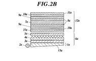
- Liquid crystal display device As an example of the configuration of a conventional liquid crystal display device, in the direct type (backlight type), as shown in FIG. 2A, from the light source side, [light source 1a / diffusion plate 3a / light collecting sheet 4a (prism sheet etc.) / Upper diffusion sheet 5a / liquid crystal panel 12a (polarizer 10a / protective film (retardation film etc.) 9a / substrate 8a / liquid crystal cell 7a / protective film 11a)], which is mainly used for large LCDs such as televisions. It is the composition which is.
- the light source 1a is composed of a light emitting light source 2a and a light guide plate 13a, and is mainly used for small LCDs for monitors and mobile applications.
- the lower diffusion sheet is an optical sheet having strong light diffusibility mainly for reducing in-plane luminance unevenness of the backlight unit (BLU) 6a, and the condensing sheet transmits diffused light in the front direction of the liquid crystal display device (display device plane).
- the upper diffusion sheet is used to reduce the moire generated by a periodic structure such as a prism sheet that is a light condensing sheet or a pixel in a liquid crystal cell, and the lower diffusion sheet. This optical sheet is used to further reduce in-plane luminance unevenness that cannot be removed by the sheet.
- the protective film for the polarizing plate of the lower polarizing plate (film 14a), and the upper diffusion sheet
- the protective film for polarizing plate of the present invention can be manufactured without requiring a coating process or a complicated process, and the cost of the entire liquid crystal display device can be reduced by adopting a configuration in which the upper diffusion sheet is removed in this way. it can.
- a surface having an arithmetic average roughness Ra (A) of 0.08 ⁇ m or more and 2.0 ⁇ m or less is disposed on the light source side, and the other The surface (B) is arranged so as to be on the liquid crystal cell side.
- Ra (A) arithmetic average roughness of 0.08 ⁇ m or more and 2.0 ⁇ m or less
- the surface (B) is arranged so as to be on the liquid crystal cell side.
- the liquid crystal cell substrate and a polarizing plate may be attached to each other.
- Liquid crystal cell display methods include twisted nematic (TN), super twisted nematic (STN), vertical alignment (VA), in-plane switching (IPS), and optically compensated bend cells (OCB). It can be preferably used for a transmissive, reflective, or transflective liquid crystal display device.
- TN twisted nematic
- STN super twisted nematic
- VA vertical alignment
- IPS in-plane switching
- OOB optically compensated bend cells
- CCFL Cold Cathode Fluorescent Lamp, cold cathode tube
- HCFL Hot Cathode Fluorescent Lamp, hot cathode tube
- LED Light Emitting Diode, light emitting diode
- OLED Organic LED
- Light-emitting diode, organic light emitting diode [organic EL], inorganic EL, and the like can be preferably used.
- Example 1 17.4 parts by weight of cellulose acetate propionate (weight average molecular weight 200,000, glass transition temperature 145 ° C., refractive index 1.474: resin e) and cellulose diacetate (weight average molecular weight 150,000, glass transition temperature 189 ° C., refraction) Rate 1.474: Resin d)
- a dope was prepared by dissolving 9.4 parts by mass in a mixed solvent of 103 parts by mass of methylene chloride and 19.6 parts by mass of ethanol. Using a belt casting apparatus, this dope was cast on a stainless steel belt with a width of 2 m.
- Example 1 of the present invention having an average film thickness of 40 ⁇ m was obtained.
- Examples 2 and 3> A film was prepared in the same manner as in Example 1 except that the draw ratio in the drawing step was 1.1 times and 1.2 times, respectively, and Example 2 and Example of the present invention each corresponding to an average film thickness of 40 ⁇ m. A film of 3 was obtained.
- Example 4 Polymethyl methacrylate (VB-7103, manufactured by Mitsubishi Rayon Co., Ltd., weight average molecular weight 300,000, glass transition temperature 105 ° C., refractive index 1.490: resin g) 28.4 parts by weight and cellulose acetate propionate (weight average molecular weight 190,000, glass transition temperature 178 ° C., refractive index 1.476: resin c) 9.5 parts by mass was dissolved in a mixed solvent of 98.7 parts by mass of methylene chloride and 13.5 parts by mass of ethanol to prepare a dope. . The dope was cast on a stainless steel belt using a belt casting apparatus.
- this dope was cast on a stainless steel belt with a width of 2 m. After the solvent was evaporated on the stainless steel belt, the web was peeled from the stainless steel belt and slit to a width of 1.6 m. Then, using a tenter while being transported, the film was stretched 1.1 times in the width direction at 110 ° C. at a stretching speed of 150% / min, and drying was completed while transporting the 100 ° C. drying zone with many rolls. The film of Example 4 of this invention with an average film thickness of 40 ⁇ m was obtained. ⁇ Examples 5 and 6> Except that the stretching temperature in the stretching process was changed to 140 ° C.
- Example 5 and Example 6 of the present invention corresponding to each of Examples 4 and 6 having an average film thickness of 40 ⁇ m was prepared.
- Got. ⁇ Comparative Examples 3 and 4> Except having changed the extending
- the arithmetic average roughness Ra, total haze, and internal haze of the films of Examples 1 to 6 and Comparative Examples 1 to 4 produced as described above were measured by the following methods. The results are shown in Table 2.
- evaluation film refers to the film produced in Examples 1 to 6 and Comparative Examples 1 to 4.
- ⁇ Fine particle shedding> The drop-off property of the particles was evaluated using a surface property measuring machine (Tribo Station TYPE32) manufactured by Shinto Kagaku Co., Ltd. First, a non-woven fabric (Bencott, manufactured by Asahi Kasei Co., Ltd.) is installed on the sliding surface of the friction element of the surface property measuring machine, and an evaluation film is placed so as to oppose it, and 10 reciprocations are performed with a load of 200 g. I let you. Then, the adhesion state of the drop-off fine particles on the surface of the nonwoven fabric was observed with an optical microscope (450 times), and the fine particle drop-off property of the film was evaluated according to the following criteria. A: Dropped fine particles were not observed at all. X: Dropped fine particles were observed.
- the "commercial item" used for the criteria of ⁇ and ⁇ is arranged so as to be adjacent to the backlight among the films used as protective films for the rear side (backlight side) polarizing plate of the notebook computer.
- the anti-glare film was peeled off from the liquid crystal cell of the above-mentioned notebook personal computer, immersed in pure water for 4 hours, and then the polarizer was peeled off from the film. Used after conditioning to 55% RH.
- front luminance was evaluated.
- a main dope having the following composition was prepared. First, methylene chloride and ethanol were added to the pressure dissolution tank. Cellulose acetate was added to a pressurized dissolution tank containing a solvent while stirring. This is completely dissolved with heating and stirring. This was designated as Azumi Filter Paper No. The main dope was prepared by filtration using 244.
- the solvent was evaporated until the amount of residual solvent in the cast (cast) film reached 75%, and then peeled off from the stainless steel belt support with a peeling tension of 130 N / m.
- the film is stretched using a tenter stretching apparatus, and then dried by being transported in a drying zone set at 130 ° C. for 30 minutes to have a film thickness of 40 ⁇ m having a width of 2 m, a width of 1 cm at an end, and a height of 8 ⁇ m.
- the optical film 1 was prepared and wound up at 5000 m.
- the retardation values Ro (590) and Rt (590) of the optical film 1 were 20 nm and 110 nm, respectively.
- a polyvinyl alcohol film having a thickness of 50 ⁇ m was uniaxially stretched in the film forming direction (temperature: 110 ° C., stretch ratio: 5 times). This was immersed in an aqueous solution composed of 0.075 g of iodine, 6 g of potassium iodide, and 100 g of water for 60 seconds, and then immersed in an aqueous solution of 68 ° C. composed of 6 g of potassium iodide, 7.5 g of boric acid, and 100 g of water. . This was washed with water and dried to obtain a polarizer. This polarizer had an absorption axis in the film forming direction.
- Process 2 The prepared evaluation film was immersed in a 4N aqueous potassium hydroxide solution at 50 ° C. for 60 seconds as a protective film for polarizing plate, then washed with water and dried to saponify the surface to be bonded to the polarizer.
- the retardation film 1 produced above was also saponified as a protective film for the polarizing plate on the opposite side.
- Process 3 The polarizer was immersed in a polyvinyl alcohol adhesive tank having a solid content of 2% by mass for 1 to 2 seconds.
- Process 4 Excess adhesive adhered to the polarizer in Step 3 was gently wiped off, and this was placed on the bonding surface of the evaluation film treated in Step 2, and further treated in Step 2 as a protective film for polarizing plate on the opposite side. Lamination was performed so that the saponified surface of the retardation film 1 was in contact with the polarizer, and a polarizing plate was obtained.
- Process 5 The polarizing plate in which the film and the polarizer were laminated in Step 4 was bonded at a pressure of 20 to 30 N / cm 2 and a conveyance speed of about 2 m / min.
- Step 6 Samples obtained by laminating the polarizer, the evaluation film, and the optical film 1 produced in Step 5 in a drier at 80 ° C. by roll-to-roll were dried for 2 minutes, and each of Examples 1 to 6 and Comparative Examples 1 to 4 was dried. A corresponding polarizing plate was prepared.
- the rear side polarizing plate of a commercially available liquid crystal monitor (manufactured by Samsung, SyncMaster 743BM) was peeled off, and the polarizing plate prepared above was bonded instead. However, when laminating to the liquid crystal cell, it is laminated so that the surface of the evaluation film faces the backlight side and the absorption axis faces in the same direction as the polarizing plate that has been preliminarily bonded. did.
- the backlight unit has a configuration of light guide plate / lower diffusion sheet / prism sheet / prism sheet in order from the light source side. Liquid crystal display devices 1 to 6 of the present invention and comparative liquid crystal display devices 1 to 4 corresponding to the films of Examples 1 to 6 and Comparative Examples 1 to 4 were produced.
- the light source of the liquid crystal display device was turned on, installed so that the panel surface was perpendicular to the floor surface, and lit for 120 minutes in an environment of 23 ° C. and 55% RH. Thereafter, the front luminance at the center of the monitor was measured in a dark room using a spectral radiance meter CS2000 manufactured by Konica Minolta (see FIG. 5).
- Evaluation was performed with respect to the front luminance when a commercially available cellulose ester film 4UY (manufactured by Konica Minolta Opto Co., Ltd.) was used as the evaluation standard, and a 4UY polarizing plate produced by the same method was used for the rear polarizing plate.
- the ratio of the front luminance of the film was calculated and evaluated according to the following criteria. A: 99% or more of the front luminance of 4 UY B: 90% or more of the front luminance of 4 UY and less than 99% X: Less than 90% of the front luminance of 4 UY About the films of Examples 1 to 6 and Comparative Examples 1 to 4 Table 2 summarizes the measurement and evaluation results.
- Example 7 17.4 parts by weight of cellulose acetate propionate (weight average molecular weight 200,000, glass transition temperature 145 ° C., refractive index 1.474: resin e) and cellulose diacetate (weight average molecular weight 130,000, glass transition temperature 180 ° C., refraction) Rate 1.475: Resin i) 9.4 parts by mass was dissolved in a mixed solvent of 103 parts by mass of methylene chloride and 19.6 parts by mass of ethanol to prepare a dope.
- cellulose acetate propionate weight average molecular weight 200,000, glass transition temperature 145 ° C., refractive index 1.474: resin e
- cellulose diacetate weight average molecular weight 130,000, glass transition temperature 180 ° C., refraction
- this dope was cast on a stainless steel belt with a width of 2 m. After the solvent was evaporated on the stainless steel belt, the web was peeled from the stainless steel belt and slit to a width of 1.6 m. Then, using a tenter while being transported, the film was stretched 1.1 times in the width direction at 170 ° C. at a stretching speed of 150% / min, and the drying was completed while transporting the 120 ° C. drying zone with a number of rolls. The film of Example 7 of the present invention having an average film thickness of 45 ⁇ m was obtained.
- Example 8> A film of Example 8 of the present invention having an average film thickness of 40 ⁇ m was obtained in the same manner as in Example 5 except that the stretching speed in the stretching step was changed to 350% / min.
- Example 9 Polymethyl methacrylate (weight average molecular weight 160,000, glass transition temperature 104 ° C., refractive index 1.489: resin j) 28.4 parts by mass and cellulose diacetate (weight average molecular weight 150,000, glass transition temperature 189 ° C., refractive index 1.474: Resin d) 9.5 parts by mass was dissolved in a mixed solvent of 98.7 parts by mass of methylene chloride and 13.5 parts by mass of ethanol to prepare a dope. The dope was cast on a stainless steel belt using a belt casting apparatus. Using a belt casting apparatus, this dope was cast on a stainless steel belt with a width of 2 m.
- Example 9 of this invention with an average film thickness of 40 ⁇ m was obtained.
- PMMA crosslinked polymethyl methacrylate fine particles
- Table 3 summarizes the measurement and evaluation results for the films of Examples 7-9 and Comparative Examples 5-7.
- the films of Examples 7 to 9 produced by the production method of the present invention were films that were compatible with both the front luminance and the moire eliminating ability when formed into a display device without the problem of brittleness.
- the present invention can be used for the production of a protective film for a backlight-side polarizing plate of a liquid crystal display device, and further to a polarizing plate and a liquid crystal display device provided with the protective film for a polarizing plate produced by the production method. Available.
Landscapes
- Chemical & Material Sciences (AREA)
- Engineering & Computer Science (AREA)
- Manufacturing & Machinery (AREA)
- Materials Engineering (AREA)
- Health & Medical Sciences (AREA)
- Chemical Kinetics & Catalysis (AREA)
- Medicinal Chemistry (AREA)
- Polymers & Plastics (AREA)
- Organic Chemistry (AREA)
- Polarising Elements (AREA)
Abstract
La présente invention concerne l'utilisation, en particulier en tant que film protecteur destiné à une plaque de polarisation côté rétroéclairage dans un appareil d'affichage à cristaux liquides, d'un film protecteur de plaque de polarisation qui peut parfaitement dissiper le moiré sans perte de luminosité frontale. La présente invention concerne aussi un procédé de fabrication associé qui permet de fabriquer le film protecteur de plaque de polarisation grâce à un processus simple ne provoquant pas de contamination suite à l'élimination de minuscules particules. En outre, la présente invention se rapporte à une plaque de polarisation et à un appareil d'affichage à cristaux liquides qui sont munis du film protecteur de plaque de polarisation fabriqué grâce à ce procédé. La présente invention a trait à un procédé de fabrication d'un film protecteur de plaque de polarisation qui possède une structure île et mer comprenant des phases continues correspondant à la mer ainsi que des phases dispersées correspondant aux îles. La présente invention est caractérisée en ce que : la différence (Tg (A) - Tg (B)) entre la température de transition vitreuse Tg (A) de la résine A, qui est le principal constituant formant les îles, et la température de transition vitreuse Tg (B) de la résine B, qui est le principal constituant formant la mer, est supérieure à 10 °C ; la valeur absolue de la différence d'indice de réfraction entre la résine A et la résine B est inférieure ou égale à 0,08 ; le procédé comporte des étapes spécifiques.
Priority Applications (1)
| Application Number | Priority Date | Filing Date | Title |
|---|---|---|---|
| JP2013512020A JP5942988B2 (ja) | 2011-04-25 | 2012-04-17 | 偏光板用保護フィルムの製造方法、偏光板用保護フィルム、偏光板及び液晶表示装置 |
Applications Claiming Priority (2)
| Application Number | Priority Date | Filing Date | Title |
|---|---|---|---|
| JP2011-096864 | 2011-04-25 | ||
| JP2011096864 | 2011-04-25 |
Publications (1)
| Publication Number | Publication Date |
|---|---|
| WO2012147562A1 true WO2012147562A1 (fr) | 2012-11-01 |
Family
ID=47072084
Family Applications (1)
| Application Number | Title | Priority Date | Filing Date |
|---|---|---|---|
| PCT/JP2012/060336 WO2012147562A1 (fr) | 2011-04-25 | 2012-04-17 | Procédé de fabrication d'un film protecteur de plaque de polarisation, film protecteur de plaque de polarisation, plaque de polarisation et appareil d'affichage à cristaux liquides |
Country Status (2)
| Country | Link |
|---|---|
| JP (1) | JP5942988B2 (fr) |
| WO (1) | WO2012147562A1 (fr) |
Cited By (2)
| Publication number | Priority date | Publication date | Assignee | Title |
|---|---|---|---|---|
| JPWO2012128239A1 (ja) * | 2011-03-22 | 2014-07-24 | コニカミノルタ株式会社 | 偏光板用保護フィルム、その製造方法、偏光板、及び液晶表示装置 |
| JP2017068223A (ja) * | 2015-10-02 | 2017-04-06 | 住友化学株式会社 | 偏光板用保護フィルム |
Citations (6)
| Publication number | Priority date | Publication date | Assignee | Title |
|---|---|---|---|---|
| JP2004131728A (ja) * | 2002-09-18 | 2004-04-30 | Toray Ind Inc | 二軸配向ポリエステルフィルム |
| JP2007178504A (ja) * | 2005-12-27 | 2007-07-12 | Toray Ind Inc | 表示装置用フィルムおよびその製造方法 |
| WO2008018279A1 (fr) * | 2006-08-07 | 2008-02-14 | Konica Minolta Opto, Inc. | film de protection de plaque de polarisation, et plaque de polarisation et dispositif d'affichage à cristaux liquides utilisant le film de protection de plaque de polarisation |
| JP2008107499A (ja) * | 2006-10-24 | 2008-05-08 | Fujifilm Corp | 偏光板及び液晶表示装置 |
| JP2009221324A (ja) * | 2008-03-14 | 2009-10-01 | Soken Chem & Eng Co Ltd | 光学部材用粘着剤およびこれを利用した光学部材用保護フィルム |
| JP2011008012A (ja) * | 2009-06-25 | 2011-01-13 | Teijin Chem Ltd | 光拡散板 |
Family Cites Families (3)
| Publication number | Priority date | Publication date | Assignee | Title |
|---|---|---|---|---|
| JP4904979B2 (ja) * | 2006-08-11 | 2012-03-28 | Dic株式会社 | 積層体 |
| WO2009047924A1 (fr) * | 2007-10-13 | 2009-04-16 | Konica Minolta Opto, Inc. | Film optique |
| WO2012128239A1 (fr) * | 2011-03-22 | 2012-09-27 | コニカミノルタアドバンストレイヤー株式会社 | Film de protection pour une plaque de polarisation, procédé de fabrication de ce dernier, plaque de polarisation et dispositif d'affichage à cristaux liquides |
-
2012
- 2012-04-17 JP JP2013512020A patent/JP5942988B2/ja active Active
- 2012-04-17 WO PCT/JP2012/060336 patent/WO2012147562A1/fr active Application Filing
Patent Citations (6)
| Publication number | Priority date | Publication date | Assignee | Title |
|---|---|---|---|---|
| JP2004131728A (ja) * | 2002-09-18 | 2004-04-30 | Toray Ind Inc | 二軸配向ポリエステルフィルム |
| JP2007178504A (ja) * | 2005-12-27 | 2007-07-12 | Toray Ind Inc | 表示装置用フィルムおよびその製造方法 |
| WO2008018279A1 (fr) * | 2006-08-07 | 2008-02-14 | Konica Minolta Opto, Inc. | film de protection de plaque de polarisation, et plaque de polarisation et dispositif d'affichage à cristaux liquides utilisant le film de protection de plaque de polarisation |
| JP2008107499A (ja) * | 2006-10-24 | 2008-05-08 | Fujifilm Corp | 偏光板及び液晶表示装置 |
| JP2009221324A (ja) * | 2008-03-14 | 2009-10-01 | Soken Chem & Eng Co Ltd | 光学部材用粘着剤およびこれを利用した光学部材用保護フィルム |
| JP2011008012A (ja) * | 2009-06-25 | 2011-01-13 | Teijin Chem Ltd | 光拡散板 |
Cited By (3)
| Publication number | Priority date | Publication date | Assignee | Title |
|---|---|---|---|---|
| JPWO2012128239A1 (ja) * | 2011-03-22 | 2014-07-24 | コニカミノルタ株式会社 | 偏光板用保護フィルム、その製造方法、偏光板、及び液晶表示装置 |
| JP2017068223A (ja) * | 2015-10-02 | 2017-04-06 | 住友化学株式会社 | 偏光板用保護フィルム |
| CN106802443A (zh) * | 2015-10-02 | 2017-06-06 | 住友化学株式会社 | 偏振板用保护膜 |
Also Published As
| Publication number | Publication date |
|---|---|
| JPWO2012147562A1 (ja) | 2014-07-28 |
| JP5942988B2 (ja) | 2016-06-29 |
Similar Documents
| Publication | Publication Date | Title |
|---|---|---|
| JP5521552B2 (ja) | アクリル樹脂含有フィルム、それを用いた偏光板及び液晶表示装置 | |
| KR101390618B1 (ko) | 광학 필름 | |
| JP5402925B2 (ja) | 偏光板及び液晶表示装置 | |
| JP2013109116A (ja) | 偏光膜保護フィルムの製造方法、偏光膜保護フィルム、偏光板及びそれを用いた液晶表示装置 | |
| TW201107396A (en) | Optical element | |
| WO2013080847A1 (fr) | Procédé de fabrication d'un film à teneur en résine acrylique | |
| JP5831540B2 (ja) | 偏光板用保護フィルム、その製造方法、偏光板、及び液晶表示装置 | |
| JP5533858B2 (ja) | 光学フィルム、それを用いた偏光板及び液晶表示装置 | |
| JP5310724B2 (ja) | 偏光板、液晶表示装置 | |
| WO2012026192A1 (fr) | Film de revêtement dur, plaque de polarisation et dispositif d'affichage à cristaux liquides | |
| JP5980465B2 (ja) | 偏光板及びそれを用いた液晶表示装置 | |
| JP5942988B2 (ja) | 偏光板用保護フィルムの製造方法、偏光板用保護フィルム、偏光板及び液晶表示装置 | |
| JP5533857B2 (ja) | 光学フィルム、それを用いた偏光板及び液晶表示装置 | |
| JP5045539B2 (ja) | 偏光板用保護フィルム、偏光板及び液晶表示装置 | |
| WO2011055590A1 (fr) | Bobine de film protecteur pour plaque de polarisation à cristaux liquides et son procédé de fabrication | |
| WO2010116830A1 (fr) | Film optique | |
| WO2009119268A1 (fr) | Film contenant une résine acrylique, procédé de production du film contenant une résine acrylique, et plaque de polarisation et dispositif d’affichage à cristaux liquides utilisant le film contenant une résine acrylique | |
| JP5810872B2 (ja) | 偏光板用保護フィルム、その製造方法、偏光板、及び液晶表示装置 | |
| JP5720509B2 (ja) | 面光源装置 | |
| WO2016052015A1 (fr) | Appareil d'affichage à cristaux liquides | |
| JP6086064B2 (ja) | 偏光板用保護フィルム、偏光板、及び液晶表示装置 | |
| JP5402941B2 (ja) | 偏光板及びそれを用いた液晶表示装置 | |
| JP2011123402A (ja) | 偏光板及びそれを用いた液晶表示装置 | |
| JP2013064814A (ja) | 光学フィルムとその製造方法 |
Legal Events
| Date | Code | Title | Description |
|---|---|---|---|
| 121 | Ep: the epo has been informed by wipo that ep was designated in this application |
Ref document number: 12777586 Country of ref document: EP Kind code of ref document: A1 |
|
| ENP | Entry into the national phase |
Ref document number: 2013512020 Country of ref document: JP Kind code of ref document: A |
|
| NENP | Non-entry into the national phase |
Ref country code: DE |
|
| 122 | Ep: pct application non-entry in european phase |
Ref document number: 12777586 Country of ref document: EP Kind code of ref document: A1 |