WO2012147387A1 - 湿式電気集塵機 - Google Patents
湿式電気集塵機 Download PDFInfo
- Publication number
- WO2012147387A1 WO2012147387A1 PCT/JP2012/052872 JP2012052872W WO2012147387A1 WO 2012147387 A1 WO2012147387 A1 WO 2012147387A1 JP 2012052872 W JP2012052872 W JP 2012052872W WO 2012147387 A1 WO2012147387 A1 WO 2012147387A1
- Authority
- WO
- WIPO (PCT)
- Prior art keywords
- exhaust gas
- dust collector
- dust
- casing
- drain tank
- Prior art date
- Legal status (The legal status is an assumption and is not a legal conclusion. Google has not performed a legal analysis and makes no representation as to the accuracy of the status listed.)
- Ceased
Links
Images


Classifications
-
- B—PERFORMING OPERATIONS; TRANSPORTING
- B03—SEPARATION OF SOLID MATERIALS USING LIQUIDS OR USING PNEUMATIC TABLES OR JIGS; MAGNETIC OR ELECTROSTATIC SEPARATION OF SOLID MATERIALS FROM SOLID MATERIALS OR FLUIDS; SEPARATION BY HIGH-VOLTAGE ELECTRIC FIELDS
- B03C—MAGNETIC OR ELECTROSTATIC SEPARATION OF SOLID MATERIALS FROM SOLID MATERIALS OR FLUIDS; SEPARATION BY HIGH-VOLTAGE ELECTRIC FIELDS
- B03C3/00—Separating dispersed particles from gases or vapour, e.g. air, by electrostatic effect
- B03C3/02—Plant or installations having external electricity supply
- B03C3/16—Plant or installations having external electricity supply wet type
-
- B—PERFORMING OPERATIONS; TRANSPORTING
- B03—SEPARATION OF SOLID MATERIALS USING LIQUIDS OR USING PNEUMATIC TABLES OR JIGS; MAGNETIC OR ELECTROSTATIC SEPARATION OF SOLID MATERIALS FROM SOLID MATERIALS OR FLUIDS; SEPARATION BY HIGH-VOLTAGE ELECTRIC FIELDS
- B03C—MAGNETIC OR ELECTROSTATIC SEPARATION OF SOLID MATERIALS FROM SOLID MATERIALS OR FLUIDS; SEPARATION BY HIGH-VOLTAGE ELECTRIC FIELDS
- B03C3/00—Separating dispersed particles from gases or vapour, e.g. air, by electrostatic effect
- B03C3/02—Plant or installations having external electricity supply
- B03C3/025—Combinations of electrostatic separators, e.g. in parallel or in series, stacked separators or dry-wet separator combinations
-
- B—PERFORMING OPERATIONS; TRANSPORTING
- B03—SEPARATION OF SOLID MATERIALS USING LIQUIDS OR USING PNEUMATIC TABLES OR JIGS; MAGNETIC OR ELECTROSTATIC SEPARATION OF SOLID MATERIALS FROM SOLID MATERIALS OR FLUIDS; SEPARATION BY HIGH-VOLTAGE ELECTRIC FIELDS
- B03C—MAGNETIC OR ELECTROSTATIC SEPARATION OF SOLID MATERIALS FROM SOLID MATERIALS OR FLUIDS; SEPARATION BY HIGH-VOLTAGE ELECTRIC FIELDS
- B03C3/00—Separating dispersed particles from gases or vapour, e.g. air, by electrostatic effect
- B03C3/34—Constructional details or accessories or operation thereof
- B03C3/36—Controlling flow of gases or vapour
- B03C3/361—Controlling flow of gases or vapour by static mechanical means, e.g. deflector
-
- B—PERFORMING OPERATIONS; TRANSPORTING
- B03—SEPARATION OF SOLID MATERIALS USING LIQUIDS OR USING PNEUMATIC TABLES OR JIGS; MAGNETIC OR ELECTROSTATIC SEPARATION OF SOLID MATERIALS FROM SOLID MATERIALS OR FLUIDS; SEPARATION BY HIGH-VOLTAGE ELECTRIC FIELDS
- B03C—MAGNETIC OR ELECTROSTATIC SEPARATION OF SOLID MATERIALS FROM SOLID MATERIALS OR FLUIDS; SEPARATION BY HIGH-VOLTAGE ELECTRIC FIELDS
- B03C3/00—Separating dispersed particles from gases or vapour, e.g. air, by electrostatic effect
- B03C3/34—Constructional details or accessories or operation thereof
- B03C3/40—Electrode constructions
- B03C3/45—Collecting-electrodes
- B03C3/49—Collecting-electrodes tubular
-
- B—PERFORMING OPERATIONS; TRANSPORTING
- B03—SEPARATION OF SOLID MATERIALS USING LIQUIDS OR USING PNEUMATIC TABLES OR JIGS; MAGNETIC OR ELECTROSTATIC SEPARATION OF SOLID MATERIALS FROM SOLID MATERIALS OR FLUIDS; SEPARATION BY HIGH-VOLTAGE ELECTRIC FIELDS
- B03C—MAGNETIC OR ELECTROSTATIC SEPARATION OF SOLID MATERIALS FROM SOLID MATERIALS OR FLUIDS; SEPARATION BY HIGH-VOLTAGE ELECTRIC FIELDS
- B03C3/00—Separating dispersed particles from gases or vapour, e.g. air, by electrostatic effect
- B03C3/34—Constructional details or accessories or operation thereof
- B03C3/74—Cleaning the electrodes
- B03C3/78—Cleaning the electrodes by washing
Definitions
- the present invention relates to a wet electrostatic precipitator, and more particularly to a wet electrostatic precipitator that eliminates the need for overhaul in a short period of time by preventing the dust collection performance from dropping over a long period of time.
- a CVD (Chemical Vapor Deposition) process for forming a film using a chemical vapor reaction, an etching process, and the like are performed, and various gases are used in a process chamber.
- the exhaust gas generated from the process chamber through a chemical vapor reaction or the like includes harmful P 4 gases (perfluorocarbon: global warming gas) such as CF 4 (Freon 14) and C 4 F 8 (Freon 318). It is. Since this PFC gas is extremely stable, it is harmful to the environment if it is released into the atmosphere without being decomposed.
- harmful P 4 gases perfluorocarbon: global warming gas
- CF 4 Fluorocarbon: global warming gas
- C 4 F 8 Freon 318
- exhaust gas is rendered harmless after passing through a combustion type or plasma type detoxifying device for exhaust gas treatment.
- the exhaust gas may contain W 2 O 5 (tungsten oxide) or SiO 2 (silicon dioxide) depending on the CVD process in addition to the above components.
- this wet type electrostatic precipitator can be increased to nearly 100%, can be stably maintained for a long period of time, and the number of maintenance can be minimized. Moreover, it is desired that the size of the wet electrostatic precipitator is small.
- the wet type electrostatic precipitator has versatility that can be easily changed in design depending on the flow rate of the exhaust gas. Furthermore, it is conceivable that this wet type electrostatic precipitator applies corona discharge from the viewpoint of dust collection efficiency, but the power source for this corona discharge should be composed of a common power source as much as possible in terms of simplification of the system and cost. Is desirable.
- the present invention has been made in view of such conventional problems, and an object of the present invention is to provide a wet type electrostatic precipitator that does not require overhaul in a short period of time by preventing the dust collection performance from deteriorating over a long period of time. To do.
- the present invention includes an exhaust gas containing dust, at least one first cylindrical dust collector that is discharged after the exhaust gas is introduced and purified, and an upper portion of the casing of the cylindrical dust collector.
- An electrode having a predetermined electric potential between the casing, a covering cylinder covering the periphery of the electrode, water flowing down in the form of a water film inside the casing, and a drain in which the casing is erected
- a wet-type electrostatic precipitator including a tank, wherein the exhaust gas is discharged from an upper portion of the casing after rising in the casing via an air reservoir in the drain tank.
- Dust in the exhaust gas is charged to negative ions by, for example, corona discharge. And this dust is drawn near to the case side which has a different voltage. Since a water film is formed inside the housing, the dust attached to the housing is washed away by this water and falls into the drain tank. The flow of the exhaust gas flows from the lower side to the upper side of the housing via the air reservoir in the drain tank. Therefore, dust is less likely to adhere to or accumulate around the coated cylinder, for example, when exhaust gas directly hits the coated cylinder. For this reason, there is no fear of electric leakage, and since it is stable over a long period of time, the dust collection performance is hardly lowered. Accordingly, the interval between overhauls can be increased. Since the number of installed cylindrical dust collectors may be set according to the flow rate of the exhaust gas, the versatility is high.
- At least one second cylindrical dust collector not having an electrode and a coating cylinder for sucking exhaust gas from the upper part of the housing on the drain tank, and the second cylindrical shape. And water that flows down in the form of a water film inside the housing of the dust collector, and after the exhaust gas descends in the housing of the second cylindrical dust collector, the first tank passes through the air reservoir in the drain tank. After rising inside the casing of the cylindrical dust collector, it is discharged from the upper part of the casing of the first cylindrical dust collector.
- the second cylindrical dust collector there is no covering cylinder that may cause dust adhering near the upper part of the casing, which is an inflow port for exhaust gas, and no electrode is provided to prevent leakage. For this reason, there is no fear of electric leakage, and since it is stable over a long period of time, the dust collection performance is hardly lowered. Accordingly, the interval between overhauls can be increased.
- the present invention (Claim 3) is characterized in that the exhaust gas is directly introduced into the drain tank.
- the present invention further includes at least one third cylindrical dust collector that discharges after the exhaust gas is introduced and purified on the drain tank, and the housing of the first cylindrical dust collector is further provided.
- the exhaust gas discharged from the upper part of the body is reintroduced into the drain tank, and after rising in the casing of the third cylindrical dust collector via the air reservoir in the drain tank, the exhaust gas is discharged from the upper part of the casing. It is characterized by that.
- the exhaust gas flows from the lower side to the upper side of the casing, so that it is difficult for dust to adhere or accumulate around the coated cylinder when the exhaust gas directly hits the coated cylinder. Become. For this reason, there is no fear of electric leakage, and since it is stable over a long period of time, the dust collection performance is hardly lowered. Accordingly, the interval between overhauls can be increased.
- the present invention (Claim 5) is characterized in that a voltage is supplied in parallel from the same power source to the electrodes.
- the possibility that the dust is attached to the periphery of the coated cylinder and the voltage is lowered due to electric leakage and the dust collection efficiency is lowered is extremely low. For this reason, there is no problem even if a voltage is supplied in parallel from the same power source to the electrodes. As a result, the wet electrostatic precipitator equipment can be configured simply and inexpensively.
- the exhaust gas rises in the casing of the cylindrical dust collector via the air reservoir in the drain tank, and is then discharged from the upper part of the casing.
- dust is less likely to adhere to or accumulate around the coated cylinder due to direct contact with exhaust gas. For this reason, there is no fear of electric leakage, and since it is stable over a long period of time, the dust collection performance is hardly lowered. Accordingly, the interval between overhauls can be increased.
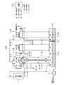
- FIG. 1 A system configuration diagram of the first embodiment of the present invention is shown in FIG. 1
- the wet electrostatic precipitator 10 has three cylindrical dust collectors 10 ⁇ / b> A, 10 ⁇ / b> B, and 10 ⁇ / b> C having substantially the same outer shape standing on the drain tank 12.
- the bottoms of the casings 11A, 11B, and 11C of the cylindrical dust collectors 10A, 10B, and 10C are communicated with the drain tank 12.
- An air reservoir is formed in the upper layer portion of the drain tank 12.
- the power terminals 21B and 21C are disposed at the upper ends of the cylindrical dust collectors 10B and 10C, and the electrode bars 23B and 23C are penetrated through the centers of the power terminals 21B and 21C. Electrode pieces 25B and 25C are attached to a plurality of locations of the electrode rods 23B and 23C at equal intervals so that corona discharge is possible.
- a suction pipe 13A is attached to the upper end side of the cylindrical dust collector 10A.
- Discharge pipes 25 and 15 are attached to the upper end sides of the cylindrical dust collectors 10B and 10C.
- Glass-coated cylinders 27B and 27C are attached around the electrode bars 23B and 23C on the bottom surfaces of the power terminals 21B and 21C in order to stably perform corona discharge.
- the exhaust gas containing dust such as W 2 O 5 and SiO 2 discharged from the abatement apparatus 1 is branched in the middle, and then introduced into the casing 11A of the cylindrical dust collector 10A through the suction pipe 13A. It has become.
- the exhaust gas is guided to the drain tank 12 after passing through the housing 11A. Thereafter, the exhaust gas rises from the drain tank 12 to the cylindrical dust collectors 10B and 10C and is discharged from the discharge pipes 15 and 25. The exhaust gas that has exited the discharge pipes 15 and 25 is guided to an exhaust duct (not shown).
- Each of the housings 11A, 11B, and 11C is grounded, and a voltage of ⁇ 25 kV is applied in parallel from the same power source 26 to the electrode rods 23B and 23C.
- the casings 11A, 11B, and 11C are constituted by double cylinders.
- a weir with an inner cylinder is formed immediately below the suction pipe 13A and the discharge pipes 15 and 25.
- a storage tank (not shown) is formed between the outer cylinder and the inner cylinder, and water is introduced through the water pipes 29A, 29B, 29C and stored in the storage tank.
- the water stored here then overflows into the drain tank 12 in a water film shape little by little along the inner cylinder wall beyond the inner cylinder.
- the water accumulated in the drain tank 12 is drained to the outside by a drain pump 31.
- the exhaust gas is introduced into the housing 11A of the cylindrical dust collector 10A through the suction pipe 13A by suction from the exhaust duct side. Thereafter, the exhaust gas falls down inside the housing 11A.
- casing 11 is low by having reversed the flow direction of waste gas by the 1st step and the 3rd step, and it can comprise in space saving.
- the inside of the casings 11B and 11C is configured such that dust in the exhaust gas rises, the dust hardly adheres around the coated cylinders 27B and 27C. For this reason, even if a water film is formed inside the casings 11B and 11C, the dust does not adhere to the surroundings of the covering cylinders 27B and 27C in a form of absorbing moisture. Accordingly, there is no risk of leakage, and the dust collection performance is not easily lowered because it is stable for a long time. The interval between overhauls can be increased.
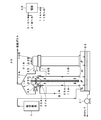
- FIG. 1 A system configuration diagram of the second embodiment of the present invention is shown in FIG. Note that the same elements as those in FIG. 1 are denoted by the same reference numerals and description thereof is omitted.
- a partition plate 37 is disposed in the air reservoir of the drain tank 12 of the wet electrostatic precipitator 20, and is partitioned into two spaces, a suction side space 12A and a discharge side space 12B.
- the partition plate not the partition plate but the drain tank itself may be separated and independent.
- the exhaust gas discharged from the abatement apparatus 1 is directly sucked into the suction side space 12A of the drain tank 12.
- the suction pipe 13A in the first embodiment of the cylindrical dust collector 10A functions as the discharge pipe 35 in the second embodiment, and is discharged from the discharge pipe 25 of the cylindrical dust collector 10B and the discharge pipe 35 of the cylindrical dust collector 10A.
- the exhaust gas is different from the first embodiment in that the exhaust gas is merged in the middle of the pipe and then sucked into the discharge side space 12B of the drain tank 12.
- the cylindrical dust collector 10A is also different from the first embodiment in that the power terminal 21A, the electrode rod 23A, the electrode piece 25A, and the covering cylinder 27A are present.
- the exhaust gas also rises from the suction side space 12A of the drain tank 12 in the housing 11A. For this reason, since the exhaust gas does not directly hit the covering cylinder 27A from the side, dust is hardly attached or deposited around the covering cylinders 27A and 27B.
- the exhaust gas rises from the discharge side space 12B in the casing 11C. Accordingly, since the exhaust gas does not directly hit the side of the coated cylinder 27C from the side, the dust hardly accumulates around the coated cylinder 27C. For this reason, while all the cylindrical dust collectors 10A, 10B, and 10C can collect dust by corona discharge, there is no risk of leakage and the dust collection performance is less than 99% because it is stable for a long time. Accordingly, the interval between overhauls can be increased.
- FIG. 3 shows a system configuration diagram of the third embodiment. Note that the same elements as those in FIG. 1 are denoted by the same reference numerals and description thereof is omitted.
- the third embodiment is different from the second embodiment in that it does not have the cylindrical dust collector 10C.
- the exhaust gas rises from the drain tank 22 to the housings 11A and 11B. For this reason, since the exhaust gas does not directly hit the coated cylinders 27A and 27B from the side, the dust hardly adheres or accumulates around the coated cylinders 27A and 27B. For this reason, there is no fear of electric leakage, and since it is stable over a long period of time, the dust collection performance is difficult to drop at 99% or more. Accordingly, the interval between overhauls can be increased. Moreover, it can be simply configured with only two cylindrical dust collectors 10A and 10B.
- FIG. 10A A system configuration diagram of the fourth embodiment is shown in FIG. Note that the same elements as those in FIG. 1 are denoted by the same reference numerals and description thereof is omitted.
- the fourth embodiment is different from the first embodiment in that the cylindrical dust collector 10A of the wet electrostatic precipitator 40 includes a power terminal 21A, an electrode bar 23A, an electrode piece 25A, and a covering cylinder 27A.
- the discharge pipe 25 in the first embodiment of the cylindrical dust collector 10B functions as the suction pipe 13B in the fourth embodiment, and includes dust such as W 2 O 5 and SiO 2 discharged from the abatement apparatus 1.
- the exhaust gas is different from the first embodiment in that the exhaust gas is branched into the middle and then introduced into the casings 11A and 11B of the cylindrical dust collectors 10A and 10B through the suction pipes 13A and 13B.
- the dust remaining in the exhaust gas is again charged to negative ions by corona discharge in the process of rising from the drain tank 12 into the housing 11C. And this dust is attracted
- the dust is efficiently removed by going through the first stage by the cylindrical dust collectors 10A and 10B, the second stage by passing through the drain tank 12, and the third stage by the cylindrical dust collector 10C.
- the introduced exhaust gas is distributed to the cylindrical dust collectors 10A and 10B, the probability that dust adheres to or accumulates around the coated cylinders 27A and 27B is reduced.
Landscapes
- Electrostatic Separation (AREA)
Abstract
集塵性能が長期間にわたり落ちないようにすることで短期間でのオーバーホールを不要とした湿式電気集塵機を提供する。 円筒状集塵機10Aにおける排ガスの流入口付近には粉塵が付着するおそれのある被覆筒27Aを配設せず、また、漏電を防ぐため電源端子21A、電極棒23A及び電極片25Aを除去している。また、円筒状集塵機10Bの吐出管25及び円筒状集塵機10Cの吐出管15から排ガスを吐出させるようにしている。筐体11Aの内壁に付着した粉塵は水と共に下方のドレインタンク12へと内壁を伝って押し流されるので粉塵を洗い落とすという効果がある。排ガスの流れは筐体11B、11Cの下方から上方へと流れる。このため、粉塵は被覆筒27B、27Cの周囲に付着したり堆積し難くなる。
Description
本発明は湿式電気集塵機(Wet Electrostatic Precipitator)に係わり、特に集塵性能が長期間にわたり落ちないようにすることで短期間でのオーバーホールを不要とした湿式電気集塵機に関する。
半導体素子の製造工程では、化学気相反応を利用して成膜するCVD(Chemical Vapor Deposition)処理やエッチング処理等が行われ、プロセスチャンバにおいて各種のガスが使用されている。
そして、このプロセスチャンバから化学気相反応等を経て発生する排ガスは、有害なCF4(フロン14)やC4F8(フロン318)などのPFCガス(パーフロロカーボン:地球温暖化ガス)が含まれている。
このPFCガスは極めて安定なため、分解されずに大気中に放出されると環境に対して害が大きい。
このPFCガスは極めて安定なため、分解されずに大気中に放出されると環境に対して害が大きい。
このため、排ガス処理のため燃焼式やプラズマ式等の除害装置に通された上で、排ガスを無害化している。そして、この排ガス中には上記成分以外にCVDプロセス如何によってW2O5(酸化タングステン)やSiO2(二酸化ケイ素)の含まれていることがある。
このW2O5やSiO2は除害装置において相当程度除去されるが、完全には除去され切れず残りは主に粉塵の形で除害装置から排出される。そこで、この残った粉塵を除去すべく除害装置の後段には湿式電気集塵機が備えられることが望ましい。この湿式電気集塵機の従来例としては例えば特許文献1に記載のものがある。
ところで、この湿式電気集塵機の集塵効率はほぼ100%に近くまで上げられ、かつ、安定的に長期間維持され、保守の回数をできるだけ少なくすることが望まれる。また、湿式電気集塵機の大きさは小型であることが望まれる。
更に、湿式電気集塵機は排出ガスの流量の大きさに応じて臨機応変に設計変更が容易な汎用性のあることが望ましい。
更に、この湿式電気集塵機は集塵効率の観点からコロナ放電等を適用することが考えられるが、このコロナ放電用の電源にはシステムの簡素化及びコスト面からできるだけ共通の電源で構成されることが望ましい。
更に、この湿式電気集塵機は集塵効率の観点からコロナ放電等を適用することが考えられるが、このコロナ放電用の電源にはシステムの簡素化及びコスト面からできるだけ共通の電源で構成されることが望ましい。
本発明はこのような従来の課題に鑑みてなされたもので、集塵性能が長期間にわたり落ちないようにすることで短期間でのオーバーホールを不要とした湿式電気集塵機を提供することを目的とする。
このため本発明(請求項1)は、粉塵を含む排ガスと、該排ガスが導入され浄化後に吐出される少なくとも1本の第1の筒状集塵機と、該筒状集塵機の筐体上部に配設され、該筐体との間に所定の電位を有する電極と、該電極の周囲を覆う被覆筒と、前記筐体の内側を水膜状に流れ落ちる水と、前記筐体が立設されたドレインタンクとを備えた湿式電気集塵機であって、前記排ガスが該ドレインタンクの空気溜まりを経由して前記筐体内を上昇した後、該筐体の上部から吐出されることを特徴とする。
排ガス中の粉塵は例えばコロナ放電等によりマイナスイオンに帯電される。そして、この粉塵は異なる電圧を有する筐体側に引き寄せられる。筐体の内側には水膜が形成されているため、この水により、筐体に付着した粉塵は流し落とされ、ドレインタンクへと落下する。
排ガスの流れはドレインタンクの空気溜まりを経由して筐体の下方から上方へと流れる。従って、被覆筒に対して直接排ガスが当たる等により粉塵が被覆筒の周囲に付着したり堆積し難くなる。このため、漏電のおそれも無く、長期にわたり安定するため集塵性能も落ちにくい。従って、オーバーホールの間隔も長くできる。排ガスの流量の大きさに応じて円筒状集塵機の設置台数を設置すればよいので汎用性が高い。
排ガスの流れはドレインタンクの空気溜まりを経由して筐体の下方から上方へと流れる。従って、被覆筒に対して直接排ガスが当たる等により粉塵が被覆筒の周囲に付着したり堆積し難くなる。このため、漏電のおそれも無く、長期にわたり安定するため集塵性能も落ちにくい。従って、オーバーホールの間隔も長くできる。排ガスの流量の大きさに応じて円筒状集塵機の設置台数を設置すればよいので汎用性が高い。
また、本発明(請求項2)は、前記ドレインタンク上には筐体上部から排ガスを吸入する電極及び被覆筒を有しない少なくとも1本の第2の筒状集塵機と、該第2の筒状集塵機の筐体の内側を水膜状に流れ落ちる水とを更に備え、前記排ガスが該第2の筒状集塵機の筐体内を下降した後、前記ドレインタンクの空気溜まりを経由して前記第1の筒状集塵機の筐体内を上昇した後、該第1の筒状集塵機の筐体の上部から吐出されることを特徴とする。
第2の円筒状集塵機における排ガスの流入口である筐体上部付近には粉塵が付着するおそれのある被覆筒を配設せず、また、漏電を防ぐため電極も配設されていない。このため、漏電のおそれも無く、長期にわたり安定するため集塵性能も落ちにくい。従って、オーバーホールの間隔も長くできる。
更に、本発明(請求項3)は、前記排ガスが前記ドレインタンクに直接導入されたことを特徴とする。
排ガスをドレインタンクに直接導入したことで、排ガスの流入口には被覆筒や電極が存在しない。このため、漏電のおそれも無く、長期にわたり安定するため集塵性能も落ちにくい。従って、オーバーホールの間隔も長くできる。
更に、本発明(請求項4)は、前記ドレインタンク上には前記排ガスが導入され浄化後に吐出される少なくとも1本の第3の筒状集塵機を更に備え、前記第1の筒状集塵機の筐体の上部から吐出された排ガスが再び前記ドレインタンクに導入され、該ドレインタンクの空気溜まりを経由して前記第3の筒状集塵機の筐体内を上昇した後、該筐体の上部から吐出されることを特徴とする。
第3の筒状集塵機の筐体内についても排ガスは筐体の下方から上方へと流れることになるので被覆筒に対して直接排ガスが当たる等により粉塵が被覆筒の周囲に付着したり堆積し難くなる。このため、漏電のおそれも無く、長期にわたり安定するため集塵性能も落ちにくい。従って、オーバーホールの間隔も長くできる。
更に、本発明(請求項5)は、前記電極には同一の電源から並列に電圧が供給されることを特徴とする。
前述したように、すべての筒状集塵機において粉塵が被覆筒の周囲に付着することで電圧が漏電により低下し集塵効率が低下するという可能性は極めて低くなった。このため、電極に対し同一の電源から並列に電圧を供給しても問題はない。このことにより、湿式電気集塵機設備を簡素かつ安価に構成できる。
以上説明したように本発明によれば、排ガスがドレインタンクの空気溜まりを経由して筒状集塵機の筐体内を上昇した後、筐体の上部から吐出されるように構成したので、被覆筒に対して直接排ガスが当たる等により粉塵が被覆筒の周囲に付着したり堆積し難くなる。このため、漏電のおそれも無く、長期にわたり安定するため集塵性能も落ちにくい。従って、オーバーホールの間隔も長くできる。
以下、本発明の第1の実施形態について説明する。本発明の第1実施形態のシステム構成図を図1に示す。
図1において、湿式電気集塵機10には、ほぼ同じ外形の3本の円筒状集塵機10A、10B、10Cがドレインタンク12上に立設されている。この円筒状集塵機10A、10B、10Cの筐体11A、11B、11Cのそれぞれの底部はドレインタンク12と連通されている。このドレインタンク12の上層部分には空気溜まりが形成されている。
円筒状集塵機10B、10Cの上端には電源端子21B、21Cが配設され、かつ、この電源端子21B、21Cの中心には電極棒23B、23Cが貫通されている。そして、この電極棒23B、23Cの複数箇所には等間隔に電極片25B、25Cが取り付けられコロナ放電が可能なようになっている。
円筒状集塵機10Aの上端側部には吸入管13Aが取り付けられている。また、円筒状集塵機10B、10Cの上端側部には吐出管25、15が取り付けられている。電源端子21B、21Cの底面の電極棒23B、23C回りにはコロナ放電が安定的に行われるようにするためガラス製の被覆筒27B、27Cが取り付けられている。
そして、除害装置1から排出されたW2O5やSiO2等の粉塵を含む排ガスは途中で分岐された後、吸入管13Aを通じて円筒状集塵機10Aの筐体11A内部に導入されるようになっている。
この際、排ガスは筐体11Aを通過した後ドレインタンク12へと導かれる。その後、排ガスはドレインタンク12から円筒状集塵機10B、10Cを昇って吐出管15、25から排出される。吐出管15、25を出た排ガスは図示しない排風ダクトへと導かれるようになっている。
筐体11A、11B、11Cのそれぞれはアースされ、電極棒23B、23Cには同一の電源26から並列に-25kVの電圧が印加されるようになっている。
また、筐体11A、11B、11Cは2重の筒で構成されている。そして、吸入管13A及び吐出管15、25の直下には内側の筒による堰が形成されている。外側の筒と内側の筒の筒同士の間には図示しない貯留槽が形成されており、水配管29A、29B、29Cを介して水が流入され、貯留槽に貯められるようになっている。
ここで貯められた水はその後、内側の筒を超えて少しずつ内側の筒壁に沿って水膜状にドレインタンク12へと溢れ落ちるようになっている。
ドレインタンク12に溜まった水は排水ポンプ31により外部へと排水されるようになっている。
ドレインタンク12に溜まった水は排水ポンプ31により外部へと排水されるようになっている。
次に、本発明の第1実施形態の動作を説明する。
排風ダクト側からの吸引により吸入管13Aを通じて円筒状集塵機10Aの筐体11A内部に排ガスは導入される。その後、排ガスは筐体11A内部を下方へと落下する。
排風ダクト側からの吸引により吸入管13Aを通じて円筒状集塵機10Aの筐体11A内部に排ガスは導入される。その後、排ガスは筐体11A内部を下方へと落下する。
筐体11Aの内側には水膜が形成されているため、この水により、筐体11Aに付着した粉塵は流し落とされ、ドレインタンク12へと落下する。筐体11Aからドレインタンク12へと出た排ガスはドレインタンク12内部に溜まった水の上を通ることで冷却され、かつ、この溜まった水に接触することで更に吸収される。
また、このドレインタンク12より筐体11B、11C内部を昇る過程で排ガス中の粉塵はコロナ放電によりマイナスイオンに帯電される。そして、この粉塵は0Vである筐体11B、11C側に静電界を利用して引き寄せられる。
筐体11B、11Cの内側には水膜が形成されているため、この水により、筐体11B、11Cに付着した粉塵は流し落とされ、ドレインタンク12へと落下する。粉塵の落とされた排ガスは吐出管15、25より吐出される。
筐体11B、11Cの内側には水膜が形成されているため、この水により、筐体11B、11Cに付着した粉塵は流し落とされ、ドレインタンク12へと落下する。粉塵の落とされた排ガスは吐出管15、25より吐出される。
以上の工程を経ることで0.3μm以上の粒径の粉塵が99%以上程度除去された排ガスにすることができる。即ち、コロナ放電による集塵作用及び水膜による落下作用に加えて排ガスがドレインタンク12内部に溜まった水の上を通ることでの水への吸収も作用するので粉塵の除去効果は高い。
即ち、粉塵は、円筒状集塵機10Aによる第1段階、ドレインタンク12内部を経過することによる第2段階、更に、円筒状集塵機10B、10Cによる第3段階の各段階を経ることで効率よく除去される。円筒状集塵機10Aではコロナ放電は行わないものの、筐体11Aの内壁に付着した粉塵は水と共に下方のドレインタンク12へと内壁を伝って押し流されるので粉塵を洗い落とすという効果がある。
また、排ガスの流量の大きさに応じて円筒状集塵機の設置台数を設置すればよいので汎用性が高い。更に、第1段階と第3段階とで排ガスの流れる方向を逆にしたことで筐体11の高さは低く、省スペースに構成できる。
筐体11B、11C内部を排ガス中の粉塵が昇るように構成したので、被覆筒27B、27Cの周囲には粉塵が付着し難い。このため、筐体11B、11Cの内側に水膜を形成したとしてもこの粉塵が水分を吸収した形で被覆筒27B、27Cの周囲に付着することはない。従って、漏電のおそれも無く、長期にわたり安定するため集塵性能も落ちにくい。オーバーホールの間隔も長くできる。
次に、本発明の第2実施形態について説明する。本発明の第2実施形態のシステム構成図を図2に示す。なお、図1と同一要素のものについては同一符号を付して説明は省略する。
図2において、湿式電気集塵機20のドレインタンク12の空気溜まりには仕切り板37が配設され吸入側空間12Aと吐出側空間12Bの2つの空間に仕切られている。但し、仕切り板では無く、ドレインタンク自体が分離独立されてもよい。
本実施形態では、図2に示すように、除害装置1から排出された排ガスはドレインタンク12の吸入側空間12Aへと直接吸入されるようになっている。
そして、円筒状集塵機10Aの第1実施形態における吸入管13Aは第2実施形態では吐出管35として機能させており、円筒状集塵機10Bの吐出管25及び円筒状集塵機10Aの吐出管35より吐出された排ガスは配管の途中で合流された後、ドレインタンク12の吐出側空間12Bに吸入されるようになっている点で第1実施形態とは相違している。
また、円筒状集塵機10Aには電源端子21A、電極棒23A、電極片25A及び被覆筒27Aが存在する点でも第1実施形態と相違する。
また、円筒状集塵機10Aには電源端子21A、電極棒23A、電極片25A及び被覆筒27Aが存在する点でも第1実施形態と相違する。
次に、本発明の第2実施形態の動作を説明する。
第2実施形態では第1実施形態とは異なり、筐体11Aについてもドレインタンク12の吸入側空間12Aより排ガスが上昇する。このため、被覆筒27Aに対しても直接排ガスが側方から当たることは無いので粉塵が被覆筒27A、27Bの周囲に付着したり堆積され難い。
第2実施形態では第1実施形態とは異なり、筐体11Aについてもドレインタンク12の吸入側空間12Aより排ガスが上昇する。このため、被覆筒27Aに対しても直接排ガスが側方から当たることは無いので粉塵が被覆筒27A、27Bの周囲に付着したり堆積され難い。
同様に、筐体11Cについても吐出側空間12Bより排ガスが上昇する。従って、被覆筒27Cに対しても直接排ガスが側方から当たることは無いので粉塵は被覆筒27Cの周囲にも堆積し難い。このため、円筒状集塵機10A、10B、10Cのすべてについてコロナ放電による集塵を可能にしつつも、漏電のおそれも無く、長期にわたり安定するため集塵性能も99%以上で落ちにくい。従って、オーバーホールの間隔も長くできる。
次に、本発明の第3実施形態について説明する。第3実施形態のシステム構成図を図3に示す。なお、図1と同一要素のものについては同一符号を付して説明は省略する。第3実施形態は第2実施形態に比べ、円筒状集塵機10Cを有さない点で相違する。
湿式電気集塵機30のドレインタンク22には筐体11A、11Bのみが立設されている。除害装置1から排出された排ガスはドレインタンク22へと直接吸入されるようになっている。円筒状集塵機10Bの吐出管25及び円筒状集塵機10Aの吐出管35より吐出された排ガスは配管の途中で合流された後、排風ダクトへと導かれるようになっている。
次に、本発明の第3実施形態の動作を説明する。
筐体11A、11Bにはドレインタンク22より排ガスが上昇する。このため、被覆筒27A、27Bに対して直接排ガスが側方から当たることは無いので粉塵は被覆筒27A、27Bの周囲に付着したり堆積し難い。このため、漏電のおそれも無く、長期にわたり安定するため集塵性能も99%以上で落ちにくい。従って、オーバーホールの間隔も長くできる。また、円筒状集塵機10A、10Bの2本のみで簡素に構成可能である。
筐体11A、11Bにはドレインタンク22より排ガスが上昇する。このため、被覆筒27A、27Bに対して直接排ガスが側方から当たることは無いので粉塵は被覆筒27A、27Bの周囲に付着したり堆積し難い。このため、漏電のおそれも無く、長期にわたり安定するため集塵性能も99%以上で落ちにくい。従って、オーバーホールの間隔も長くできる。また、円筒状集塵機10A、10Bの2本のみで簡素に構成可能である。
次に、本発明の第4実施形態について説明する。第4実施形態のシステム構成図を図4に示す。なお、図1と同一要素のものについては同一符号を付して説明は省略する。
第4実施形態は、湿式電気集塵機40の円筒状集塵機10Aには電源端子21A、電極棒23A、電極片25A及び被覆筒27Aが存在する点で第1実施形態と相違する。
第4実施形態は、湿式電気集塵機40の円筒状集塵機10Aには電源端子21A、電極棒23A、電極片25A及び被覆筒27Aが存在する点で第1実施形態と相違する。
そして、円筒状集塵機10Bの第1実施形態における吐出管25は第4実施形態では吸入管13Bとして機能させており、除害装置1から排出されたW2O5やSiO2等の粉塵を含む排ガスは途中で分岐された後、吸入管13A、13Bを通じて円筒状集塵機10A、10Bの筐体11A、11B内部に導入されるようになっている点で第1実施形態と相違する。
次に、本発明の第4実施形態の動作を説明する。
排風ダクト側からの吸引により吸入管13A、13Bを通じて円筒状集塵機10A、10Bの筐体11A、11B内部に排ガスは導入される。このとき、排ガスは、円筒状集塵機10A、10Bの筐体11A、11B内部に分配されて導入される為、各円筒状集塵機で処理される粉塵の量も半分になっている。その後、排ガスは筐体11A、11B内部を下方へと落下するが、この際、排ガス中の粉塵はコロナ放電によりマイナスイオンに帯電される。そして、この粉塵は0Vである筐体11A、11B側に静電界を利用して引き寄せられる。
排風ダクト側からの吸引により吸入管13A、13Bを通じて円筒状集塵機10A、10Bの筐体11A、11B内部に排ガスは導入される。このとき、排ガスは、円筒状集塵機10A、10Bの筐体11A、11B内部に分配されて導入される為、各円筒状集塵機で処理される粉塵の量も半分になっている。その後、排ガスは筐体11A、11B内部を下方へと落下するが、この際、排ガス中の粉塵はコロナ放電によりマイナスイオンに帯電される。そして、この粉塵は0Vである筐体11A、11B側に静電界を利用して引き寄せられる。
筐体11A、11Bの内側には水膜が形成されているため、この水により、筐体11A、11Bに付着した粉塵は流し落とされ、ドレインタンク12へと落下する。筐体11A、11Bからドレインタンク12へと出た排ガスはドレインタンク12内部に溜まった水の上を通ることで冷却され、かつ、この溜まった水に接触することで更に吸収される。
また、このドレインタンク12より筐体11C内部を昇る過程で再び排ガス中の残っている粉塵はコロナ放電によりマイナスイオンに帯電される。そして、この粉塵は0Vである筐体11C側に静電界を利用して引き寄せられる。
筐体11Cの内側には水膜が形成されているため、この水により、筐体11Cに付着した粉塵は流し落とされ、ドレインタンク12へと落下する。粉塵の落とされた排ガスは吐出管15より吐出される。
筐体11Cの内側には水膜が形成されているため、この水により、筐体11Cに付着した粉塵は流し落とされ、ドレインタンク12へと落下する。粉塵の落とされた排ガスは吐出管15より吐出される。
以上の工程を経ることで0.3μm以上の粒径の粉塵が99%以上程度除去された排ガスにすることができる。即ち、コロナ放電による集塵作用及び水膜による落下作用に加えて排ガスがドレインタンク12内部に溜まった水の上を通ることでの水への吸収も作用するので粉塵の除去効果は高い。
即ち、粉塵は、円筒状集塵機10A、10Bによる第1段階、ドレインタンク12内部を経過することによる第2段階、更に、円筒状集塵機10Cによる第3段階の各段階を経ることで効率よく除去される。また、導入される排ガスが円筒集塵機10Aと10Bに分配されることで、粉塵が被覆筒27A、27Bの周囲に付着したり堆積したりする確率は低減している。
筐体11Cにはドレインタンク12より排ガスが上昇する。このため、被覆筒27Cに対して直接排ガスが側方から当たることは無いので粉塵は被覆筒27Cの周囲に付着したり堆積し難い。このため、漏電のおそれも無く、長期にわたり安定するため集塵性能も99%以上で落ちにくい。従って、円筒状集塵機10Cのオーバーホールの間隔を長くできる。
1 除害装置
10、20、30、40 湿式電気集塵機
10A、10B、10C 円筒状集塵機
11A、11B、11C 筐体
12、22 ドレインタンク
12A ドレインタンク吸入側空間
12B ドレインタンク吐出側空間
13A、13B 吸入管
15、25、35 吐出管
21A、21B、21C 電源端子
23A、23B、23C 電極棒
25A、25B、25C 電極片
26 電源
27A、27B、27C 被覆筒
29A、29B、29C 水配管
37 仕切り板
10、20、30、40 湿式電気集塵機
10A、10B、10C 円筒状集塵機
11A、11B、11C 筐体
12、22 ドレインタンク
12A ドレインタンク吸入側空間
12B ドレインタンク吐出側空間
13A、13B 吸入管
15、25、35 吐出管
21A、21B、21C 電源端子
23A、23B、23C 電極棒
25A、25B、25C 電極片
26 電源
27A、27B、27C 被覆筒
29A、29B、29C 水配管
37 仕切り板
Claims (5)
- 粉塵を含む排ガスと、
該排ガスが導入され浄化後に吐出される少なくとも1本の第1の筒状集塵機(10)と、
該第1の筒状集塵機の筐体(11)の上部に配設され、該筐体との間に所定の電位を有する電極(21、23、25)と、
該電極の周囲を覆う被覆筒(27)と、
前記筐体の内側を水膜状に流れ落ちる水と、
前記筐体が立設されたドレインタンク(12、22)とを備えた湿式電気集塵機であって、
前記排ガスが該ドレインタンクの空気溜まりを経由して前記筐体内を上昇した後、該筐体の上部から吐出されることを特徴とする湿式電気集塵機。 - 前記ドレインタンク(12)上には、筐体(11A)上部から前記排ガスを吸入する電極及び被覆筒を有しない少なくとも1本の第2の筒状集塵機(10A)と、
該第2の筒状集塵機の筐体(11A)の内側を水膜状に流れ落ちる水とを更に備え、
前記排ガスが該第2の筒状集塵機の筐体内を下降した後、前記ドレインタンク(12)の空気溜まりを経由して前記第1の筒状集塵機(10B、10C)の筐体(11B、11C)内を上昇した後、該第1の筒状集塵機の筐体の上部から吐出されることを特徴とする請求項1記載の湿式電気集塵機。 - 前記排ガスが前記ドレインタンク(12、22)に直接導入されたことを特徴とする請求項1記載の湿式電気集塵機。
- 前記ドレインタンク(12)上には前記排ガスが導入され浄化後に吐出される少なくとも1本の第3の筒状集塵機(10C)を更に備え、
前記第1の筒状集塵機(10A、10B)の筐体(11A、11B)の上部から吐出された前記排ガスが再び前記ドレインタンク(12)に導入され、該ドレインタンクの空気溜まりを経由して前記第3の筒状集塵機の筐体(11C)内を上昇した後、該筐体の上部から吐出されることを特徴とする請求項1、2又は3記載の湿式電気集塵機。 - 前記電極には同一の電源(26)から並列に電圧が供給されることを特徴とする請求項1、2、3又は4記載の湿式電気集塵機。
Applications Claiming Priority (2)
| Application Number | Priority Date | Filing Date | Title |
|---|---|---|---|
| JP2011100702 | 2011-04-28 | ||
| JP2011-100702 | 2011-04-28 |
Publications (1)
| Publication Number | Publication Date |
|---|---|
| WO2012147387A1 true WO2012147387A1 (ja) | 2012-11-01 |
Family
ID=47071916
Family Applications (1)
| Application Number | Title | Priority Date | Filing Date |
|---|---|---|---|
| PCT/JP2012/052872 Ceased WO2012147387A1 (ja) | 2011-04-28 | 2012-02-08 | 湿式電気集塵機 |
Country Status (1)
| Country | Link |
|---|---|
| WO (1) | WO2012147387A1 (ja) |
Cited By (1)
| Publication number | Priority date | Publication date | Assignee | Title |
|---|---|---|---|---|
| WO2016135438A1 (en) * | 2015-02-23 | 2016-09-01 | Edwards Limited | Apparatus for treating gas |
Citations (6)
| Publication number | Priority date | Publication date | Assignee | Title |
|---|---|---|---|---|
| JPS5329275A (en) * | 1976-08-31 | 1978-03-18 | Nippon Earo Piyuuru Kk | Purification exhaust gases |
| JPS5770452U (ja) * | 1980-10-17 | 1982-04-28 | ||
| JPS61132053U (ja) * | 1985-02-07 | 1986-08-18 | ||
| JP2001269395A (ja) * | 2000-03-27 | 2001-10-02 | Yamakei:Kk | 脱臭装置 |
| JP2006272127A (ja) * | 2005-03-29 | 2006-10-12 | Matsushita Electric Ind Co Ltd | 集塵装置 |
| JP2010269259A (ja) * | 2009-05-22 | 2010-12-02 | Techno Ryowa Ltd | 空気清浄機 |
-
2012
- 2012-02-08 WO PCT/JP2012/052872 patent/WO2012147387A1/ja not_active Ceased
Patent Citations (6)
| Publication number | Priority date | Publication date | Assignee | Title |
|---|---|---|---|---|
| JPS5329275A (en) * | 1976-08-31 | 1978-03-18 | Nippon Earo Piyuuru Kk | Purification exhaust gases |
| JPS5770452U (ja) * | 1980-10-17 | 1982-04-28 | ||
| JPS61132053U (ja) * | 1985-02-07 | 1986-08-18 | ||
| JP2001269395A (ja) * | 2000-03-27 | 2001-10-02 | Yamakei:Kk | 脱臭装置 |
| JP2006272127A (ja) * | 2005-03-29 | 2006-10-12 | Matsushita Electric Ind Co Ltd | 集塵装置 |
| JP2010269259A (ja) * | 2009-05-22 | 2010-12-02 | Techno Ryowa Ltd | 空気清浄機 |
Cited By (8)
| Publication number | Priority date | Publication date | Assignee | Title |
|---|---|---|---|---|
| WO2016135438A1 (en) * | 2015-02-23 | 2016-09-01 | Edwards Limited | Apparatus for treating gas |
| CN107249753A (zh) * | 2015-02-23 | 2017-10-13 | 爱德华兹有限公司 | 用于处理气体的设备 |
| KR20170118753A (ko) * | 2015-02-23 | 2017-10-25 | 에드워즈 리미티드 | 가스 처리 장치 |
| JP2018505780A (ja) * | 2015-02-23 | 2018-03-01 | エドワーズ リミテッド | ガス処理装置 |
| US20180071751A1 (en) * | 2015-02-23 | 2018-03-15 | Edwards Limited | Apparatus for treating gas |
| CN107249753B (zh) * | 2015-02-23 | 2020-06-05 | 爱德华兹有限公司 | 用于处理气体的设备 |
| US10814336B2 (en) | 2015-02-23 | 2020-10-27 | Edwards Limited | Apparatus for treating gas |
| KR102510274B1 (ko) * | 2015-02-23 | 2023-03-15 | 에드워즈 리미티드 | 가스 처리 장치 |
Similar Documents
| Publication | Publication Date | Title |
|---|---|---|
| JP6367123B2 (ja) | 集塵装置、集塵システム及び集塵方法 | |
| US8888900B2 (en) | Apparatus for treating gas | |
| JP2022508871A (ja) | 空気除塵システム及び方法 | |
| WO2011162023A1 (ja) | ガス処理システム | |
| CN108295603A (zh) | 一种电气自动化自清洗式除尘设备 | |
| KR20190143125A (ko) | 지하철 역사 내 지하수를 이용한 공기 정화장치 | |
| TW202402374A (zh) | 真空前級中用於粒子收集的高效率捕捉器 | |
| TWI754983B (zh) | 用於半導體製造的潔淨室系統及其電場除塵方法 | |
| CN106999951B (zh) | 湿式静电除尘器以及处理废气的方法 | |
| KR20100093807A (ko) | 탄소섬유를 이용한 1단 전기집진기 | |
| CN105214839B (zh) | 一种湿式除雾器 | |
| CN216419782U (zh) | 一种长流水湿式静电除尘、捕焦、消白设备 | |
| CN111940139B (zh) | 自生风空气净化器 | |
| CN103611403A (zh) | 集成式高效废气净化系统 | |
| KR20130024589A (ko) | 전기집진 장치 및 그 방법 | |
| CN211587059U (zh) | 一种能够同步净化和清洗的气体净化系统及气体净化装置 | |
| CN110882844B (zh) | 一种立式空气净化装置 | |
| CN105797866A (zh) | 一种免清洗的湿式静电净化装置 | |
| CN120205323A (zh) | 一种免冲洗湿式电除尘器 | |
| CN214717515U (zh) | 一种油烟净化器内置高压静电除油装置 | |
| CN205109867U (zh) | 一种湿式除雾器 | |
| CN212467656U (zh) | 一种VOCs废气处理喷淋塔 | |
| CN105327778A (zh) | 一种废气离子除尘净化器 | |
| CN223069680U (zh) | 一种湿式静电除尘器除尘清理装置 | |
| CN221934202U (zh) | 一种用于铁矿烧结的湿电除尘装置 |
Legal Events
| Date | Code | Title | Description |
|---|---|---|---|
| 121 | Ep: the epo has been informed by wipo that ep was designated in this application |
Ref document number: 12777140 Country of ref document: EP Kind code of ref document: A1 |
|
| NENP | Non-entry into the national phase |
Ref country code: DE |
|
| 122 | Ep: pct application non-entry in european phase |
Ref document number: 12777140 Country of ref document: EP Kind code of ref document: A1 |
|
| NENP | Non-entry into the national phase |
Ref country code: JP |