WO2012147153A1 - 吸着式除湿機 - Google Patents
吸着式除湿機 Download PDFInfo
- Publication number
- WO2012147153A1 WO2012147153A1 PCT/JP2011/060103 JP2011060103W WO2012147153A1 WO 2012147153 A1 WO2012147153 A1 WO 2012147153A1 JP 2011060103 W JP2011060103 W JP 2011060103W WO 2012147153 A1 WO2012147153 A1 WO 2012147153A1
- Authority
- WO
- WIPO (PCT)
- Prior art keywords
- air
- desorption
- zone
- adsorption
- desorption zone
- Prior art date
- Legal status (The legal status is an assumption and is not a legal conclusion. Google has not performed a legal analysis and makes no representation as to the accuracy of the status listed.)
- Ceased
Links
Images


Classifications
-
- B—PERFORMING OPERATIONS; TRANSPORTING
- B01—PHYSICAL OR CHEMICAL PROCESSES OR APPARATUS IN GENERAL
- B01D—SEPARATION
- B01D53/00—Separation of gases or vapours; Recovering vapours of volatile solvents from gases; Chemical or biological purification of waste gases, e.g. engine exhaust gases, smoke, fumes, flue gases, aerosols
- B01D53/26—Drying gases or vapours
- B01D53/261—Drying gases or vapours by adsorption
-
- B—PERFORMING OPERATIONS; TRANSPORTING
- B01—PHYSICAL OR CHEMICAL PROCESSES OR APPARATUS IN GENERAL
- B01D—SEPARATION
- B01D53/00—Separation of gases or vapours; Recovering vapours of volatile solvents from gases; Chemical or biological purification of waste gases, e.g. engine exhaust gases, smoke, fumes, flue gases, aerosols
- B01D53/02—Separation of gases or vapours; Recovering vapours of volatile solvents from gases; Chemical or biological purification of waste gases, e.g. engine exhaust gases, smoke, fumes, flue gases, aerosols by adsorption, e.g. preparative gas chromatography
- B01D53/06—Separation of gases or vapours; Recovering vapours of volatile solvents from gases; Chemical or biological purification of waste gases, e.g. engine exhaust gases, smoke, fumes, flue gases, aerosols by adsorption, e.g. preparative gas chromatography with moving adsorbents, e.g. rotating beds
-
- B—PERFORMING OPERATIONS; TRANSPORTING
- B01—PHYSICAL OR CHEMICAL PROCESSES OR APPARATUS IN GENERAL
- B01D—SEPARATION
- B01D2259/00—Type of treatment
- B01D2259/40—Further details for adsorption processes and devices
- B01D2259/40083—Regeneration of adsorbents in processes other than pressure or temperature swing adsorption
- B01D2259/40088—Regeneration of adsorbents in processes other than pressure or temperature swing adsorption by heating
- B01D2259/4009—Regeneration of adsorbents in processes other than pressure or temperature swing adsorption by heating using hot gas
Definitions
- the present invention relates to an adsorption dehumidifier capable of supplying low dew point air with low temperature desorption air.
- Low dew point air with an absolute humidity of 1.5 g / kg or less is required in lithium battery manufacturing factories and certain pharmaceutical factories, and refrigeration dehumidifiers are insufficient to create such an environment.
- An adsorption dehumidifier having a rotor is used.
- the refrigeration dehumidifier is more energy efficient than the adsorption dehumidifier, and it is necessary to take energy saving measures for the adsorption dehumidifier. If the temperature of the desorption air of the dehumidification rotor can be lowered in response to such a requirement, waste heat can be used as a heating energy source for the desorption air, and as a result, the energy saving effect is enhanced.
- Patent Document 1 Such a requirement required solving the trade-off problem of lowering the desorption temperature while increasing the adsorption capacity of the dehumidifying rotor.
- Patent Document 1 has two adsorption zones, the adsorption zone is advanced while removing the heat of adsorption, and the desorption zones are further divided into two stages, and a heater is provided in each desorption zone. It is provided.
- Patent Document 2 branches a part of the dehumidified dry air and mixes it with the air that has exited the purge zone to form desorbed air.
- the problem to be solved is to enable desorption at a lower temperature. It also simplifies the air line and reduces air resistance, thereby reducing the energy consumed by the fan.
- the main feature of the present invention is to provide an adsorption type dehumidifier capable of supplying air having a low dew point even with low-temperature desorption air.
- the adsorption type dehumidifier of the present invention is provided with two desorption zones, desorbing through the outside air in the first desorption zone containing a lot of moisture, and desorbing by flowing dry air into the desorption zone in the latter stage with low humidity. Therefore, in the first-stage desorption zone, the amount of desorbed water is large even when outside air is used, and in the latter-stage desorption zone, there is little moisture, but desorption is performed using dry air.Therefore, the desorption is sufficiently performed even at a low desorption temperature. is there.
- the temperature of the desorption air may be low, waste heat can be used as a heat source for the heater.
- dry air can be supplied with very little energy.
- the cooling water of the engine of a diesel generator can be passed through a radiator, and this radiator can be used as a heater.
- the discarded energy can be used as the main driving energy of the adsorption dehumidifier of the present invention, and the energy saving effect is high.
- waste heat is always generated from the diesel generator, and the waste heat is thrown away, so there is a lot of energy wasted, but with the desorption air at low temperature like the adsorption dehumidifier of the present invention. Anything that can supply air with a low dew point can make use of such discarded energy.
- FIG. 1 is a flowchart in Example 1 of an adsorption dehumidifier.
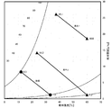
- FIG. 2 is an air diagram in the embodiment of the adsorption type dehumidifier.
- FIG. 3 is a flowchart in Example 2 of the adsorption type dehumidifier.
- the adsorption type dehumidifier of the present invention cools and dehumidifies the outside air and passes it through the adsorption zone of the dehumidification rotor, and provides two desorption zones.
- the first stage desorption zone containing a lot of moisture desorbs through the outside air, Since the desorption zone in the rear stage with a small amount of dry air is desorbed by flowing dry air, the purpose of supplying low dew point air with low temperature desorption air is realized with the minimum number of parts, and the energy saving effect is enhanced.
- Numeral 1 is a dehumidifying rotor which carries an adsorbent such as silica gel or zeolite, and many techniques are already known.
- the dehumidifying rotor 1 is rotationally driven by a geared motor (not shown) in the direction of the arrow in FIG.
- the dehumidifying rotor 1 is divided into an adsorption zone 2, a first desorption zone 3, and a second desorption zone 4.
- the area ratio of each zone of the adsorption zone 2, the first desorption zone 3, and the second desorption zone 4 is 5: 3: 1.
- OA outside air
- 6 is a cooler, for example, an evaporator connected to a refrigerator.
- Reference numerals 7 and 8 denote a first heater and a second heater, respectively, for example, a condenser of a refrigerator connected to the cooler 6 or a radiator through which a coolant of a diesel generator flows.
- the blower 5 sucks OA 1, and the air coming out of it passes through the cooler 6 and enters the adsorption zone 2 of the dehumidifying rotor 1.
- Part of the air that has passed through the adsorption zone 2 of the dehumidifying rotor 1 is branched, and the remaining air is supplied as product air (hereinafter referred to as “DA”) to a dry room (not shown).
- DA product air
- the branched air passes through the second heater 8 and enters the second desorption zone 4, and the air that has passed through the second desorption zone 4 returns to the suction side of the blower 5.
- OA 2 passes through the first heater 7, passes through the first desorption zone 3 of the dehumidifying rotor 1, is sucked into the suction side of the blower 9, and is discharged into the atmosphere as exhaust (hereinafter referred to as “EA”).
- EA exhaust
- the air volume ratio passing through each zone is the same as the area ratio of each zone 5: 3: 1. That is, the area of the second desorption zone 4 is smaller than the area of the first desorption zone 3.
- the adsorption dehumidifier of the present invention has the above-described configuration, and the operation thereof will be described below.
- all temperatures are expressed in degrees Celsius.
- the air condition of OA was 35 degrees and relative humidity 53 percent (absolute humidity 18.6 g / kg).
- This OA was sent to the cooler 6 by the blower 5 and dehumidified by condensation.
- the air condition was 12 degrees and the absolute humidity was 8.3 g / kg.
- the cooled air passes through the adsorption zone 2 of the dehumidifying rotor 1 and is further adsorbed and dehumidified. At this time, the temperature rose due to the heat of adsorption, and the air became 32 ° C. and the absolute humidity was 1.2 g / kg.
- This dry air is supplied to the dry room as product air (hereinafter referred to as “DA”).
- DA product air
- the change in air conditions as it passes through the adsorption zone 2 is indicated by the line “Process” in FIG.
- the OA2 is heated to 60 degrees by the first heater 7 and sent to the first desorption zone 3 of the dehumidifying rotor 1.
- the first desorption zone 3 is the portion with the most moisture, and a large amount of moisture is desorbed even when the temperature of the desorption air is 60 degrees. That is, air with an absolute humidity of 18.6 g / kg is 25.1 g / kg.
- the air condition passing through the first desorption zone 3 is represented by the line “Regeneration 1” in FIG.
- the air leaving the first desorption zone 3 has a high moisture content and is released to the atmosphere as exhaust (hereinafter referred to as “EA”).
- a part of the dry air that has passed through the adsorption zone 2 is branched, heated by the second heater 8, and sent to the second desorption zone 4.
- the humidity of the dehumidifying rotor 1 is considerably reduced.
- the absolute humidity of the air sent to the second desorption zone 4 is as extremely low as 1.2 g / kg, desorption proceeds further.
- the air changes from a temperature of 60 degrees and an absolute humidity of 1.2 g / kg to a temperature of 23.6 degrees and an absolute humidity of 14.2 g / kg. This change is indicated by the line “Regeneration 2” in FIG.
- the temperature of both the first heater 7 and the second heater 8 is 60 degrees, air having an absolute humidity of 1.2 g / kg can be supplied as DA. If it is 60 degrees, many waste heat sources can be used as waste heat. For example, the temperature of the coolant of a diesel generator engine is about 80 degrees, which is sufficiently usable. Also, there are refrigerators with a condenser of about 60 degrees. Furthermore, solar water heaters can supply hot water at 60 degrees even in spring and autumn, and such heat sources can also be used.
- the second desorption zone 4 having a small remaining amount of moisture can be sufficiently desorbed even if the area is smaller than the area of the first desorption zone 3, thereby reducing the amount of air passing through the second desorption zone 4. It can be reduced and the energy saving effect is higher.
- reference numeral 10 denotes a switching valve, which switches between the air that has exited the second desorption zone 4 of the dehumidifying rotor 1 flowing to the suction side of the blower 9 or the suction side of the blower 5.
- the operation is exactly the same as in the first embodiment.
- the absolute humidity of OA is lower than the absolute humidity of the air leaving the second desorption zone 4
- the air leaving the second desorption zone 4 was released into the atmosphere as EA rather than being circulated to the adsorption zone 2.
- the humidity of DA is lower. That is, the switching valve 10 can be switched according to the weather conditions to supply the air with the lowest humidity.
- the adsorption type dehumidifier of the present invention can supply air with a low dew point even if low temperature waste heat is used, and can exhibit an extremely high energy saving effect.
Landscapes
- Chemical & Material Sciences (AREA)
- Engineering & Computer Science (AREA)
- Analytical Chemistry (AREA)
- General Chemical & Material Sciences (AREA)
- Oil, Petroleum & Natural Gas (AREA)
- Chemical Kinetics & Catalysis (AREA)
- Drying Of Gases (AREA)
Abstract
本発明は、低温の脱着空気でも低露点の空気を供給できる吸着式除湿機を提供することを最も主要な特徴とする。 本発明の吸着式除湿機は、外気を冷却除湿して除湿ロータ1の吸着ゾーン2に通すようにするとともに、除湿ロータ1に第1脱着ゾーン3及び第2脱着ゾーン4の2つの脱着ゾーンを設け、湿気を多く含む初段の第1脱着ゾーン3には外気を加熱して通して脱着し、湿気の少ない後段の第2脱着ゾーン4には吸着ゾーン2を出た乾燥空気を流して脱着するようにしたため、低い温度の脱着空気で低露点の空気を供給するという目的を、最小の部品点数で実現し、省エネルギー効果を高めた。
Description
本発明は、低い温度の脱着空気で低露点の空気の供給が可能な吸着式除湿機に関するものである。
リチウム電池の製造工場や、特定の製薬工場などで絶対湿度が1.5g/kg以下の低露点空気が必要であり、このような環境を作るために冷凍式除湿機では不十分であり、除湿ロータを有する吸着式除湿機が用いられている。
しかし、一般には冷凍式除湿機の方が吸着式除湿機よりもエネルギー効率が高く、吸着式除湿機に省エネルギーの対策をする必要がある。このような要求に対して、除湿ロータの脱着空気の温度を低くする事ができれば、脱着空気の加熱エネルギー源として、廃熱を活用することができ、結果として省エネルギー効果が高くなる。
このような要求は、除湿ロータの吸着能力を高くしつつ脱着温度を下げるという二律背反の問題を解決する必要があった。この解決策として特許文献1に開示された技術がある。つまり特許文献1に開示された技術は、吸着ゾーンを2段にして後段の吸着ゾーンでは吸着熱を除去しながら吸着を進め、さらに脱着ゾーンも2段として、それぞれの脱着ゾーンに加熱用ヒータを設けたものである。
また特許文献2に開示されたものは、除湿後の乾燥空気の一部を分岐して、パージゾーンを出た空気とを混合して脱着空気としている。
解決しようとする問題点は、さらに低温の温度で脱着できるようにする点である。また空気の管路をより簡単にして、空気抵抗を減らし、これによってファンの消費エネルギーも減らすものである。
本発明は、低温の脱着空気でも低露点の空気を供給できる吸着式除湿機を提供することを最も主要な特徴とする。
本発明の吸着式除湿機は、脱着ゾーンを2つ設け、湿気を多く含む初段の脱着ゾーンには外気を通して脱着し、湿気の少ない後段の脱着ゾーンには乾燥空気を流して脱着するようにするため、初段の脱着ゾーンでは外気を用いても脱着水分量が多く、後段の脱着ゾーンでは水分が少ないが乾燥空気を使って脱着しているため、低い脱着温度でも脱着が十分行われるという利点がある。
また、脱着ゾーンの一方のみに乾燥空気を送るようにしているため、乾燥空気の脱着での使用量を抑えることができる。
脱着ゾーンが2つあるものの、後段の脱着ゾーンを出た空気を吸着ゾーンへ入れるようにする事で、吸着用のブロアと前段の脱着ゾーン用ブロアの2つでよく、或いは2つの脱着ゾーンそれぞれの出口を1つにまとめ、共通のブロアで脱着ゾーンの空気を大気放出するようにする事で、脱着用のブロアが1つでよくコストの上昇を抑えることができる。
そして脱着空気の温度が低くてもよいため、ヒータの熱源として廃熱を用いることができ、この場合には極めて少ないエネルギーで乾燥空気の供給を行う事ができる。例えばディーゼル発電機のエンジンの冷却水をラジエターに通し、このラジエターをヒータとして利用することができる。この場合には、捨てられるエネルギーで本発明の吸着式除湿機の主な駆動エネルギーとする事ができ、省エネルギー効果が高い。
工場などの非常用電源としてディーゼル発電機を用いる場合、停電を感知後短時間で非常用電源に切り替える必要がある。このような場合には、停電を感知してからディーゼル発電機を起動したのでは、非常用電源への切り替えに時間が掛かる。このためディーゼル発電機を常時運転しておき、停電の瞬間に商用電源から非常用電源へと切り替えを行うようにしている場合が多い。
上記のような状況では、ディーゼル発電機から常時廃熱が発生し、その廃熱を捨てているため、エネルギーの無駄が多かったが、本発明の吸着式除湿機のように低温の脱着空気で低露点の空気を供給できるものでは、そのように捨てられているエネルギーを利用することが可能である。
本発明の吸着式除湿機は、外気を冷却除湿して除湿ロータの吸着ゾーンに通すようにするとともに、脱着ゾーンを2つ設け、湿気を多く含む初段の脱着ゾーンには外気を通して脱着し、湿気の少ない後段の脱着ゾーンには乾燥空気を流して脱着するようにしたため、低い温度の脱着空気で低露点の空気を供給するという目的を、最小の部品点数で実現し、省エネルギー効果を高めた。
1は除湿ロータであり、シリカゲルやゼオライトなどの吸着剤の担持されたもので、既に多くの技術が公知である。この除湿ロータ1は、図1の矢印方向にギヤドモータ(図示せず)によって回転駆動される。そして除湿ロータ1は吸着ゾーン2、第1脱着ゾーン3、第2脱着ゾーン4に分割されている。この吸着ゾーン2、第1脱着ゾーン3、第2脱着ゾーン4の各ゾーンの面積比は5:3:1である。
5はブロアで外気(以下「OA」と書く)を除湿ロータ1の吸着ゾーン2へ送るものである。6は冷却器であり、例えば冷凍機に接続されたエバポレータである。7及び8はそれぞれ第1ヒータおよび第2ヒータであり、例えば冷却器6に接続された冷凍機のコンデンサ或いは、ディーゼル発電機の冷却液が流れるラジエターである。
ブロア5はOA1を吸い込み、そこから出た空気は冷却器6を通過して除湿ロータ1の吸着ゾーン2に入る。除湿ロータ1の吸着ゾーン2を通過した空気の一部は分岐され、残りの空気は製品空気(以下「DA」と書く)となってドライルーム(図示せず)に供給される。その分岐された空気は第2ヒータ8を通過して、第2脱着ゾーン4に入り、第2脱着ゾーン4を通過した空気はブロア5の吸い込み側に戻る。
OA2は第1ヒータ7を通過し、除湿ロータ1の第1脱着ゾーン3を通過してブロア9の吸い込み側に吸い込まれ、排気(以下「EA」と書く)となって大気放出される。除湿ロータ1の吸着ゾーン2、第1脱着ゾーン3、第2脱着ゾーン4各ゾーンを通過する空気の速度を一致させると、各ゾーンを通過する風量比は、各ゾーンの面積比と同じ5:3:1となる。つまり第2脱着ゾーン4の面積が第1脱着ゾーン3の面積よりも小さい。
本発明の吸着式除湿機は以上のような構成であり、以下その動作を説明する。以下の説明で温度は全て摂氏で表す。低露点の空気を供給するのに、最も条件の厳しい盛夏の状態を想定する。この場合OAの空気条件は、35度で相対湿度53パーセント(絶対湿度18.6g/kg)であった。
このOAがブロア5によって冷却器6に送られ、結露によって除湿され、空気条件は12度で絶対湿度が8.3g/kgとなった。この冷却された空気は除湿ロータ1の吸着ゾーン2を通過し、さらに吸着除湿される。この際に、吸着熱によって温度が上昇し、32度、絶対湿度1.2g/kgの空気となった。この乾燥空気を製品空気(以下「DA」と書く)としてドライルームに供給する。吸着ゾーン2を通過する際の空気条件の変化は、図2の線「処理」で示される。
OA2は第1ヒータ7によって60度まで加熱され、除湿ロータ1の第1脱着ゾーン3へ送られる。第1脱着ゾーン3は水分の最も多い部分であり、脱着空気の温度が60度であっても多くの水分が脱着される。つまり絶対湿度18.6g/kgの空気が25.1g/kgとなる。第1脱着ゾーン3を通過する空気条件は、図2の線「再生1」で表される。第1脱着ゾーン3を出た空気は湿分が多く、排気(以下「EA」と書く)として大気へ放出される。
吸着ゾーン2を通過した乾燥空気の一部は分岐され、第2ヒータ8で加熱されて第2脱着ゾーン4へ送られる。この第2脱着ゾーン4では除湿ロータ1の湿気はかなり減少している。しかし、第2脱着ゾーン4に送られる空気は絶対湿度が1.2g/kgと極めて低いため、さらに脱着が進む。第2脱着ゾーン4を通過することによって、空気は温度60度、絶対湿度1.2g/kgから、温度23.6度、絶対湿度14.2g/kgになる。この変化は図2の線「再生2」で示される。
第2脱着ゾーン4を出た空気の絶対湿度は14.2g/kgであり、OAの絶対湿度18.6g/kgより低いため、この空気をブロア5の吸い込み側に供給し、OAと混合する事によって除湿性能が確保される。
このように第1ヒータ7、第2ヒータ8とも温度が60度であっても、DAとして絶対湿度1.2g/kgの空気を供給することができる。60度であると、廃熱として多くの廃熱源が利用できる。例えばディーゼル発電機のエンジンの冷却液の温度は80度程度であり、十分に利用可能である。また冷凍機のコンデンサも60度程度のものがある。さらに太陽熱温水器は春季や秋季でも60度の温水供給が可能であり、このような熱源も利用可能である。
特に湿気の残量の少ない第2脱着ゾーン4は面積が第1脱着ゾーン3の面積よりも小さくても十分に脱着を行う事ができ、これによって第2脱着ゾーン4を通過する空気の量を少なくすることができ、より省エネルギー効果が高い。
本発明の実施例2のものは、実施例1のものと比較して次の点が相違している。それ以外については実施例1のものと同一であり、冗長性を避けるため重複した説明を行わない。図3において、10は切り替えバルブであり、除湿ロータ1の第2脱着ゾーン4を出た空気をブロア9の吸い込み側へ流すか、ブロア5の吸い込み側に流すか、切り替えるものである。
つまり図3の切り替えバルブ10内の仕切り板が実線の状態であると、第2脱着ゾーン4を出た空気をブロア5の吸い込み側へ流れ、切り替えバルブ10内の仕切り板が破線の状態であると、第2脱着ゾーン4を出た空気をブロア9の吸い込み側へ流れる。
第2脱着ゾーン4を出た空気をブロア5の吸い込み側へ流れるようにすると、動作は上記の実施例1の状態と全く同一となる。ここで、OAの絶対湿度が第2脱着ゾーン4を出た空気の絶対湿度よりも低くなった場合、第2脱着ゾーン4を出た空気を吸着ゾーン2へ循環させるよりもEAとして大気放出した方が、DAの湿度が低くなる。つまり気象条件に合わせて切り替えバルブ10を切り替え、最も湿度の低い空気を供給するようにする事ができる。
本発明の吸着式除湿機は、低温の廃熱を利用しても低露点の空気を供給でき、極めて高い省エネルギー効果を発揮できる。
1 除湿ロータ
2 吸着ゾーン
3 第1脱着ゾーン
4 第2脱着ゾーン
5 ブロア
6 冷却器
7 第1ヒータ
8 第2ヒータ
9 ブロア
10 切り替えバルブ
2 吸着ゾーン
3 第1脱着ゾーン
4 第2脱着ゾーン
5 ブロア
6 冷却器
7 第1ヒータ
8 第2ヒータ
9 ブロア
10 切り替えバルブ
Claims (4)
- 外気を冷却除湿して除湿ロータの吸着ゾーンに通すようにするとともに、脱着ゾーンを2つ設け、湿気を多く含む初段の脱着ゾーンには外気を通して脱着し、湿気の少ない後段の脱着ゾーンには前記吸着ゾーンを出た乾燥空気を流して脱着するようにしたことを特徴とする吸着式除湿機。
- 後段の脱着ゾーンを前段の脱着ゾーンより面積を小さくしたことを特徴とする請求項1記載の吸着式除湿機。
- 後段の脱着ゾーンを出た空気を、冷却除湿の前に戻すようにしたことを特徴とする請求項1記載の吸着式除湿機。
- 後段の脱着ゾーンを出た空気を、冷却除湿の前に戻すか、大気放出するようにするか、切り替えるバルブを設けたことを特徴とする請求項1記載の吸着式除湿機。
Priority Applications (1)
| Application Number | Priority Date | Filing Date | Title |
|---|---|---|---|
| PCT/JP2011/060103 WO2012147153A1 (ja) | 2011-04-26 | 2011-04-26 | 吸着式除湿機 |
Applications Claiming Priority (1)
| Application Number | Priority Date | Filing Date | Title |
|---|---|---|---|
| PCT/JP2011/060103 WO2012147153A1 (ja) | 2011-04-26 | 2011-04-26 | 吸着式除湿機 |
Publications (1)
| Publication Number | Publication Date |
|---|---|
| WO2012147153A1 true WO2012147153A1 (ja) | 2012-11-01 |
Family
ID=47071696
Family Applications (1)
| Application Number | Title | Priority Date | Filing Date |
|---|---|---|---|
| PCT/JP2011/060103 Ceased WO2012147153A1 (ja) | 2011-04-26 | 2011-04-26 | 吸着式除湿機 |
Country Status (1)
| Country | Link |
|---|---|
| WO (1) | WO2012147153A1 (ja) |
Cited By (4)
| Publication number | Priority date | Publication date | Assignee | Title |
|---|---|---|---|---|
| CN107970748A (zh) * | 2016-10-25 | 2018-05-01 | 阿特拉斯·科普柯空气动力股份有限公司 | 压缩机设备和干燥压缩气体的方法 |
| CN111111382A (zh) * | 2018-10-30 | 2020-05-08 | 华懋科技股份有限公司 | 具有高温脱附的转轮系统及其方法 |
| WO2021033101A1 (en) * | 2019-08-16 | 2021-02-25 | Atlas Copco Airpower N.V. | Dryer for compressed gas, compressor installation provided with a dryer and a method for drying compressed gas |
| BE1027507B1 (nl) * | 2019-08-16 | 2021-03-17 | Atlas Copco Airpower Nv | Droger voor samengeperst gas, compressorinstallatie voorzien van droger en werkwijze voor het drogen van samengeperst gas |
Citations (3)
| Publication number | Priority date | Publication date | Assignee | Title |
|---|---|---|---|---|
| JPS6171821A (ja) * | 1984-07-30 | 1986-04-12 | Daikin Ind Ltd | 乾式除湿装置 |
| JPH11128649A (ja) * | 1997-10-15 | 1999-05-18 | Seibu Giken Co Ltd | ガス吸着装置 |
| JP2002320817A (ja) * | 2001-04-24 | 2002-11-05 | Takasago Thermal Eng Co Ltd | 除湿装置及び除湿方法 |
-
2011
- 2011-04-26 WO PCT/JP2011/060103 patent/WO2012147153A1/ja not_active Ceased
Patent Citations (3)
| Publication number | Priority date | Publication date | Assignee | Title |
|---|---|---|---|---|
| JPS6171821A (ja) * | 1984-07-30 | 1986-04-12 | Daikin Ind Ltd | 乾式除湿装置 |
| JPH11128649A (ja) * | 1997-10-15 | 1999-05-18 | Seibu Giken Co Ltd | ガス吸着装置 |
| JP2002320817A (ja) * | 2001-04-24 | 2002-11-05 | Takasago Thermal Eng Co Ltd | 除湿装置及び除湿方法 |
Cited By (11)
| Publication number | Priority date | Publication date | Assignee | Title |
|---|---|---|---|---|
| CN107970748A (zh) * | 2016-10-25 | 2018-05-01 | 阿特拉斯·科普柯空气动力股份有限公司 | 压缩机设备和干燥压缩气体的方法 |
| JP2018069235A (ja) * | 2016-10-25 | 2018-05-10 | アトラス コプコ エアーパワー,ナームローゼ フェンノ | 圧縮ガス用乾燥装置を有する圧縮機設備及び圧縮ガスを乾燥させる方法 |
| EP3446770A1 (en) * | 2016-10-25 | 2019-02-27 | ATLAS COPCO AIRPOWER, naamloze vennootschap | Compressor installation with drying device for compressed gas and method for drying compressed gas |
| US10576411B2 (en) | 2016-10-25 | 2020-03-03 | Atlas Copco Airpower, Naamloze Vennootschap | Compressor installation with drying device for compressed gas and method for drying compressed gas |
| CN107970748B (zh) * | 2016-10-25 | 2021-07-27 | 阿特拉斯·科普柯空气动力股份有限公司 | 压缩机设备和干燥压缩气体的方法 |
| CN113385002A (zh) * | 2016-10-25 | 2021-09-14 | 阿特拉斯·科普柯空气动力股份有限公司 | 压缩机设备和干燥压缩气体的方法 |
| EP3915664A1 (en) * | 2016-10-25 | 2021-12-01 | Atlas Copco Airpower N.V. | Compressor installation with drying device for compressed gas and method for drying compressed gas |
| US11247166B2 (en) | 2016-10-25 | 2022-02-15 | Atlas Copco Airpower, Naamloze Vennootschap | Compressor installation with drying device for compressed gas and method for drying compressed gas |
| CN111111382A (zh) * | 2018-10-30 | 2020-05-08 | 华懋科技股份有限公司 | 具有高温脱附的转轮系统及其方法 |
| WO2021033101A1 (en) * | 2019-08-16 | 2021-02-25 | Atlas Copco Airpower N.V. | Dryer for compressed gas, compressor installation provided with a dryer and a method for drying compressed gas |
| BE1027507B1 (nl) * | 2019-08-16 | 2021-03-17 | Atlas Copco Airpower Nv | Droger voor samengeperst gas, compressorinstallatie voorzien van droger en werkwijze voor het drogen van samengeperst gas |
Similar Documents
| Publication | Publication Date | Title |
|---|---|---|
| CN100551480C (zh) | 除湿系统 | |
| US8850840B2 (en) | Desiccant air conditioner | |
| JP6251311B2 (ja) | 低露点乾燥室用低温再生デシカント除湿システム | |
| US20230022397A1 (en) | Air quality adjustment system | |
| JP5885781B2 (ja) | 除湿装置および除湿システム | |
| JP2010131583A (ja) | 低消費電力の除湿装置 | |
| JP2019018157A (ja) | 除湿空調装置 | |
| JP5521106B1 (ja) | 除湿システム | |
| EP1064504A1 (en) | Desiccant assisted air conditioning system | |
| JP6550121B2 (ja) | 吸着式ハイブリッド除湿冷房システム | |
| JP5844611B2 (ja) | デシカント空気調和装置 | |
| JP5772479B2 (ja) | 空気調和装置 | |
| JP2017044387A (ja) | 除湿システム | |
| JP5683838B2 (ja) | 吸着式除湿機 | |
| JP5215233B2 (ja) | 除湿機 | |
| JP2006326504A (ja) | 除湿装置 | |
| JP2014129984A (ja) | 除湿システム | |
| JP2011104542A (ja) | 吸着式除湿装置 | |
| JP5978158B2 (ja) | 空調システム | |
| JP2017009187A (ja) | 空調装置 | |
| JP2002349905A (ja) | 暖房対応型デシカント空調装置 | |
| CN223283159U (zh) | 一种除湿系统 | |
| CN103406000A (zh) | 利用低温不饱和空气进行除湿的方法和装置 | |
| JP2011196562A (ja) | 加湿装置 | |
| JP2012006415A (ja) | 鉄道車両用空調装置 |
Legal Events
| Date | Code | Title | Description |
|---|---|---|---|
| 121 | Ep: the epo has been informed by wipo that ep was designated in this application |
Ref document number: 11864271 Country of ref document: EP Kind code of ref document: A1 |
|
| NENP | Non-entry into the national phase |
Ref country code: DE |
|
| 122 | Ep: pct application non-entry in european phase |
Ref document number: 11864271 Country of ref document: EP Kind code of ref document: A1 |