WO2012144504A1 - 細胞活性化装置 - Google Patents
細胞活性化装置 Download PDFInfo
- Publication number
- WO2012144504A1 WO2012144504A1 PCT/JP2012/060410 JP2012060410W WO2012144504A1 WO 2012144504 A1 WO2012144504 A1 WO 2012144504A1 JP 2012060410 W JP2012060410 W JP 2012060410W WO 2012144504 A1 WO2012144504 A1 WO 2012144504A1
- Authority
- WO
- WIPO (PCT)
- Prior art keywords
- infrared
- wavelength
- infrared rays
- cell activation
- activation device
- Prior art date
Links
- 230000020411 cell activation Effects 0.000 title claims abstract description 47
- 206010028980 Neoplasm Diseases 0.000 claims abstract description 74
- 201000011510 cancer Diseases 0.000 claims abstract description 74
- 230000005855 radiation Effects 0.000 claims description 36
- 239000011148 porous material Substances 0.000 claims description 22
- XLYOFNOQVPJJNP-UHFFFAOYSA-N water Substances O XLYOFNOQVPJJNP-UHFFFAOYSA-N 0.000 claims description 22
- VYPSYNLAJGMNEJ-UHFFFAOYSA-N Silicium dioxide Chemical compound O=[Si]=O VYPSYNLAJGMNEJ-UHFFFAOYSA-N 0.000 claims description 9
- 210000004027 cell Anatomy 0.000 abstract description 110
- 108090000623 proteins and genes Proteins 0.000 abstract description 30
- 230000008263 repair mechanism Effects 0.000 abstract description 12
- 230000001678 irradiating effect Effects 0.000 abstract description 5
- 206010020843 Hyperthermia Diseases 0.000 abstract description 3
- 230000036031 hyperthermia Effects 0.000 abstract description 3
- 238000002560 therapeutic procedure Methods 0.000 abstract 2
- 230000008029 eradication Effects 0.000 abstract 1
- 210000005260 human cell Anatomy 0.000 abstract 1
- 239000000463 material Substances 0.000 description 39
- 238000002474 experimental method Methods 0.000 description 20
- 230000003595 spectral effect Effects 0.000 description 18
- 238000002834 transmittance Methods 0.000 description 15
- 238000010586 diagram Methods 0.000 description 12
- 230000000694 effects Effects 0.000 description 12
- 238000000034 method Methods 0.000 description 12
- 230000008439 repair process Effects 0.000 description 10
- 241000699666 Mus <mouse, genus> Species 0.000 description 9
- CURLTUGMZLYLDI-UHFFFAOYSA-N Carbon dioxide Chemical compound O=C=O CURLTUGMZLYLDI-UHFFFAOYSA-N 0.000 description 8
- 230000036760 body temperature Effects 0.000 description 8
- 230000003287 optical effect Effects 0.000 description 8
- 239000000919 ceramic Substances 0.000 description 6
- 238000011580 nude mouse model Methods 0.000 description 5
- 239000004793 Polystyrene Substances 0.000 description 4
- 230000001640 apoptogenic effect Effects 0.000 description 4
- 230000006907 apoptotic process Effects 0.000 description 4
- 229910002092 carbon dioxide Inorganic materials 0.000 description 4
- 239000001569 carbon dioxide Substances 0.000 description 4
- 230000010261 cell growth Effects 0.000 description 4
- 238000001816 cooling Methods 0.000 description 4
- 229920002223 polystyrene Polymers 0.000 description 4
- XUIMIQQOPSSXEZ-UHFFFAOYSA-N Silicon Chemical compound [Si] XUIMIQQOPSSXEZ-UHFFFAOYSA-N 0.000 description 3
- 210000000805 cytoplasm Anatomy 0.000 description 3
- 239000000203 mixture Substances 0.000 description 3
- 230000002829 reductive effect Effects 0.000 description 3
- 229910052710 silicon Inorganic materials 0.000 description 3
- 239000010703 silicon Substances 0.000 description 3
- 241000699660 Mus musculus Species 0.000 description 2
- 206010060862 Prostate cancer Diseases 0.000 description 2
- 208000000236 Prostatic Neoplasms Diseases 0.000 description 2
- 230000009471 action Effects 0.000 description 2
- 230000003213 activating effect Effects 0.000 description 2
- 230000032683 aging Effects 0.000 description 2
- 210000002421 cell wall Anatomy 0.000 description 2
- 230000003111 delayed effect Effects 0.000 description 2
- 230000009982 effect on human Effects 0.000 description 2
- 210000002919 epithelial cell Anatomy 0.000 description 2
- 230000012010 growth Effects 0.000 description 2
- 229920005990 polystyrene resin Polymers 0.000 description 2
- 238000011160 research Methods 0.000 description 2
- 238000001356 surgical procedure Methods 0.000 description 2
- MXHRCPNRJAMMIM-SHYZEUOFSA-N 2'-deoxyuridine Chemical compound C1[C@H](O)[C@@H](CO)O[C@H]1N1C(=O)NC(=O)C=C1 MXHRCPNRJAMMIM-SHYZEUOFSA-N 0.000 description 1
- 108091003079 Bovine Serum Albumin Proteins 0.000 description 1
- RYGMFSIKBFXOCR-UHFFFAOYSA-N Copper Chemical compound [Cu] RYGMFSIKBFXOCR-UHFFFAOYSA-N 0.000 description 1
- 108010008286 DNA nucleotidylexotransferase Proteins 0.000 description 1
- 102100033215 DNA nucleotidylexotransferase Human genes 0.000 description 1
- AHCYMLUZIRLXAA-SHYZEUOFSA-N Deoxyuridine 5'-triphosphate Chemical compound O1[C@H](COP(O)(=O)OP(O)(=O)OP(O)(O)=O)[C@@H](O)C[C@@H]1N1C(=O)NC(=O)C=C1 AHCYMLUZIRLXAA-SHYZEUOFSA-N 0.000 description 1
- HTTJABKRGRZYRN-UHFFFAOYSA-N Heparin Chemical compound OC1C(NC(=O)C)C(O)OC(COS(O)(=O)=O)C1OC1C(OS(O)(=O)=O)C(O)C(OC2C(C(OS(O)(=O)=O)C(OC3C(C(O)C(O)C(O3)C(O)=O)OS(O)(=O)=O)C(CO)O2)NS(O)(=O)=O)C(C(O)=O)O1 HTTJABKRGRZYRN-UHFFFAOYSA-N 0.000 description 1
- ZDXPYRJPNDTMRX-VKHMYHEASA-N L-glutamine Chemical compound OC(=O)[C@@H](N)CCC(N)=O ZDXPYRJPNDTMRX-VKHMYHEASA-N 0.000 description 1
- 229930182816 L-glutamine Natural products 0.000 description 1
- 241000699670 Mus sp. Species 0.000 description 1
- 229930182555 Penicillin Natural products 0.000 description 1
- JGSARLDLIJGVTE-MBNYWOFBSA-N Penicillin G Chemical compound N([C@H]1[C@H]2SC([C@@H](N2C1=O)C(O)=O)(C)C)C(=O)CC1=CC=CC=C1 JGSARLDLIJGVTE-MBNYWOFBSA-N 0.000 description 1
- 210000001744 T-lymphocyte Anatomy 0.000 description 1
- 230000002159 abnormal effect Effects 0.000 description 1
- 230000005856 abnormality Effects 0.000 description 1
- 238000000862 absorption spectrum Methods 0.000 description 1
- 229910052782 aluminium Inorganic materials 0.000 description 1
- XAGFODPZIPBFFR-UHFFFAOYSA-N aluminium Chemical compound [Al] XAGFODPZIPBFFR-UHFFFAOYSA-N 0.000 description 1
- 150000001413 amino acids Chemical class 0.000 description 1
- 230000003466 anti-cipated effect Effects 0.000 description 1
- 238000003782 apoptosis assay Methods 0.000 description 1
- 238000003556 assay Methods 0.000 description 1
- 210000004369 blood Anatomy 0.000 description 1
- 239000008280 blood Substances 0.000 description 1
- 230000005907 cancer growth Effects 0.000 description 1
- 231100000504 carcinogenesis Toxicity 0.000 description 1
- 230000032677 cell aging Effects 0.000 description 1
- 230000004663 cell proliferation Effects 0.000 description 1
- 238000002737 cell proliferation kit Methods 0.000 description 1
- 238000002512 chemotherapy Methods 0.000 description 1
- 239000002826 coolant Substances 0.000 description 1
- 229910052802 copper Inorganic materials 0.000 description 1
- 239000010949 copper Substances 0.000 description 1
- 230000034994 death Effects 0.000 description 1
- 230000003247 decreasing effect Effects 0.000 description 1
- MXHRCPNRJAMMIM-UHFFFAOYSA-N desoxyuridine Natural products C1C(O)C(CO)OC1N1C(=O)NC(=O)C=C1 MXHRCPNRJAMMIM-UHFFFAOYSA-N 0.000 description 1
- 238000001514 detection method Methods 0.000 description 1
- 201000010099 disease Diseases 0.000 description 1
- 208000037265 diseases, disorders, signs and symptoms Diseases 0.000 description 1
- 230000005059 dormancy Effects 0.000 description 1
- 230000007613 environmental effect Effects 0.000 description 1
- 239000012091 fetal bovine serum Substances 0.000 description 1
- 230000017525 heat dissipation Effects 0.000 description 1
- 230000020169 heat generation Effects 0.000 description 1
- 229960002897 heparin Drugs 0.000 description 1
- 229920000669 heparin Polymers 0.000 description 1
- 230000002427 irreversible effect Effects 0.000 description 1
- 230000002147 killing effect Effects 0.000 description 1
- 238000002372 labelling Methods 0.000 description 1
- 230000001404 mediated effect Effects 0.000 description 1
- 239000007769 metal material Substances 0.000 description 1
- 210000003470 mitochondria Anatomy 0.000 description 1
- 230000002438 mitochondrial effect Effects 0.000 description 1
- 238000012986 modification Methods 0.000 description 1
- 230000004048 modification Effects 0.000 description 1
- 238000010606 normalization Methods 0.000 description 1
- 210000000633 nuclear envelope Anatomy 0.000 description 1
- 210000004940 nucleus Anatomy 0.000 description 1
- 230000036961 partial effect Effects 0.000 description 1
- 229940049954 penicillin Drugs 0.000 description 1
- 230000005522 programmed cell death Effects 0.000 description 1
- 230000035755 proliferation Effects 0.000 description 1
- 230000002035 prolonged effect Effects 0.000 description 1
- XJMOSONTPMZWPB-UHFFFAOYSA-M propidium iodide Chemical compound [I-].[I-].C12=CC(N)=CC=C2C2=CC=C(N)C=C2[N+](CCC[N+](C)(CC)CC)=C1C1=CC=CC=C1 XJMOSONTPMZWPB-UHFFFAOYSA-M 0.000 description 1
- 239000012857 radioactive material Substances 0.000 description 1
- 238000001959 radiotherapy Methods 0.000 description 1
- 238000012827 research and development Methods 0.000 description 1
- 229920005989 resin Polymers 0.000 description 1
- 239000011347 resin Substances 0.000 description 1
- -1 roof tiles Substances 0.000 description 1
- 239000002210 silicon-based material Substances 0.000 description 1
- 230000008961 swelling Effects 0.000 description 1
- 210000001519 tissue Anatomy 0.000 description 1
- 230000001131 transforming effect Effects 0.000 description 1
- 235000011178 triphosphate Nutrition 0.000 description 1
- 239000001226 triphosphate Substances 0.000 description 1
- UNXRWKVEANCORM-UHFFFAOYSA-N triphosphoric acid Chemical compound OP(O)(=O)OP(O)(=O)OP(O)(O)=O UNXRWKVEANCORM-UHFFFAOYSA-N 0.000 description 1
- 230000004614 tumor growth Effects 0.000 description 1
- 230000002477 vacuolizing effect Effects 0.000 description 1
- 238000012800 visualization Methods 0.000 description 1
Images


Classifications
-
- A—HUMAN NECESSITIES
- A61—MEDICAL OR VETERINARY SCIENCE; HYGIENE
- A61N—ELECTROTHERAPY; MAGNETOTHERAPY; RADIATION THERAPY; ULTRASOUND THERAPY
- A61N5/00—Radiation therapy
- A61N5/06—Radiation therapy using light
- A61N5/0613—Apparatus adapted for a specific treatment
-
- A—HUMAN NECESSITIES
- A61—MEDICAL OR VETERINARY SCIENCE; HYGIENE
- A61N—ELECTROTHERAPY; MAGNETOTHERAPY; RADIATION THERAPY; ULTRASOUND THERAPY
- A61N5/00—Radiation therapy
- A61N5/06—Radiation therapy using light
- A61N5/0613—Apparatus adapted for a specific treatment
- A61N5/0625—Warming the body, e.g. hyperthermia treatment
-
- A—HUMAN NECESSITIES
- A61—MEDICAL OR VETERINARY SCIENCE; HYGIENE
- A61N—ELECTROTHERAPY; MAGNETOTHERAPY; RADIATION THERAPY; ULTRASOUND THERAPY
- A61N5/00—Radiation therapy
- A61N5/06—Radiation therapy using light
- A61N2005/0658—Radiation therapy using light characterised by the wavelength of light used
- A61N2005/0659—Radiation therapy using light characterised by the wavelength of light used infrared
-
- A—HUMAN NECESSITIES
- A61—MEDICAL OR VETERINARY SCIENCE; HYGIENE
- A61N—ELECTROTHERAPY; MAGNETOTHERAPY; RADIATION THERAPY; ULTRASOUND THERAPY
- A61N5/00—Radiation therapy
- A61N5/06—Radiation therapy using light
- A61N2005/0664—Details
- A61N2005/0667—Filters
-
- F—MECHANICAL ENGINEERING; LIGHTING; HEATING; WEAPONS; BLASTING
- F04—POSITIVE - DISPLACEMENT MACHINES FOR LIQUIDS; PUMPS FOR LIQUIDS OR ELASTIC FLUIDS
- F04C—ROTARY-PISTON, OR OSCILLATING-PISTON, POSITIVE-DISPLACEMENT MACHINES FOR LIQUIDS; ROTARY-PISTON, OR OSCILLATING-PISTON, POSITIVE-DISPLACEMENT PUMPS
- F04C2270/00—Control; Monitoring or safety arrangements
- F04C2270/04—Force
- F04C2270/042—Force radial
- F04C2270/0421—Controlled or regulated
Definitions
- the present invention relates to a cell activation device that supports cell activation.
- the present invention relates to a cell activation device that acts on cancer cells and surrounding cells, activates a gene repair mechanism inherent in the cells, suppresses the growth of cancer cells, and extinguishes cancer cells.
- Patent Document 1 Japanese Patent Laid-Open No. 2003-126275.
- Patent Document 1 Japanese Patent Laid-Open No. 2003-126275.
- the affected part and the whole body are irradiated with infrared rays that mainly act as heat rays.
- this hyperthermia it is said that it is necessary to raise the body temperature in the deep part of the affected area to about 41 ° C. to 42 ° C.
- Patent Document 1 a patient is placed in a capsule-like container that hermetically accommodates the whole body other than the head, irradiated with infrared rays, and radiated heat by the infrared irradiation means and conduction heat by air in the sealed container are used for other than the patient's head.
- a technique has been disclosed in which the whole body is heated and the deep body temperature of the affected area reaches 41 ° C. to 42.5 ° C. in a short time.
- Patent Document 1 has the following problems. First, in the technique of Patent Document 1, it is necessary to warm the blood to 45 ° C. to 46 ° C. in order to raise the body temperature of the whole body or the affected part to about 41 ° C. to 42 ° C. For example, heparin or the like is administered, so that the treatment time is limited to about 1 hour, and a physical burden that cannot stand up for several days after the treatment occurs.
- an object of the present invention is to provide a cell activation device capable of activating a gene repair circuit inherent in a cell by irradiation with infrared rays and extracting a cell activation effect.
- Inventor Hiroki Shima who has been researching cancer treatment for many years as a doctor, has come to discover cancer treatment methods that are more effective than conventional cancer treatment methods. This research has been highly evaluated in the world, and has been published in the electronic version of the English scientific journal "Nature” (Nature Preceding: hdl: 10101 / npre. 2008.1980.1: Posted 17 Jun 2008).
- the cell activation device of the present invention was developed on the basis of new knowledge obtained by the inventor Hiroki Shima, who further advanced research, and the cells are irradiated by irradiating the cells with infrared rays with a configuration different from the conventional technology. It activates the original gene repair circuit.
- the cell activation device of the present invention is a cell activation device that irradiates cells with infrared rays, and includes a heat source unit, a temperature control unit, and an infrared radiator unit, and the infrared radiation unit unit is provided via the temperature control unit.
- a cell activation device that controls the wavelength of radiation and radiates only infrared rays having a wavelength of 7.5 ⁇ m or less (infrared rays having a wavelength not less than the wavelength of visible light and not more than 7.5 ⁇ m) from the infrared radiator portion. is there.
- the surface of the infrared radiator portion is provided with a filter that transmits only infrared light having a wavelength of 7.5 ⁇ m or less, and mainly blocks infrared light having a wavelength greater than 7.5 ⁇ m that acts as a heat ray, It is preferable that the cell is irradiated with only infrared rays having a wavelength of 7.5 ⁇ m or less.
- pores are provided on the surface of the infrared radiator, and by setting the pore diameter to 15 ⁇ m or less, infrared rays having a wavelength larger than 7.5 ⁇ m, which mainly acts as heat rays, can be generated. It is preferable that the cell is irradiated with only infrared rays having a wavelength of 7.5 ⁇ m or less.
- the depth of the pores on the surface of the infrared radiator portion is larger than the diameter so that the radiation from the infrared radiator portion has directivity.
- the said structure is larger than 7.5 micrometers which acts as a 1st filter which is the water filter which filled the inside with the quartz glass container on the surface of the said infrared radiation body part, and mainly acts as a heat ray. It is preferable to provide a second filter that blocks infrared rays having a wavelength.
- the temperature control unit is to maintain the temperature distribution of the heat source unit to be substantially constant, and to maintain the surface temperature of the infrared radiator to be within a specific temperature range. It is preferable that
- the cell activation device of the present invention cuts the wavelength that heats the body greatly as a heat ray out of infrared rays, and irradiates only infrared rays having a wavelength of 7.5 ⁇ m or less, thereby improving the gene repair mechanism of each cell. It can be activated and has the effect of transforming cancer cells into normal cells and extinguishing cancer cells by setting up an apoptotic circuit. In addition, an effect of preventing normal cells around cancer cells from becoming cancerous can be expected. In addition, since the cell activation device of the present invention can activate normal cells, it is effective not only for preventing cancer but also for preventing other diseases.
- Diagram showing the spectral reflectance of the rubber material used in this experiment Diagram showing the spectral transmittance of a petri dish made of polystyrene, the spectral transmittance of a flexible disk made of polystyrene, and the spectral transmittance of silicon
- the figure which shows the experimental result which irradiated infrared rays with a wavelength of 7.5 micrometers or less with respect to a human cancer cell and a normal cell A diagram showing the spectral transmittance of water molecules and carbon dioxide molecules in the atmosphere, which is a clue to knowing the infrared transmittance of water molecules
- FIG. The figure which shows the result of the experiment shown in FIG.
- FIG. The figure which shows typically the relationship between the depth (d) and diameter (r) of a pore, and the directivity of the infrared rays reflected
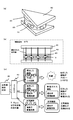
- FIG. 1 is a diagram showing an outline of an experiment for confirming the effect on human cancer cells by irradiation with infrared rays having a wavelength of 7.5 ⁇ m or less using a cancer cell specimen.
- the specimen 10 and the culture solution 20 are placed in a petri dish 40, an infrared radiation material 30a is disposed on the upper side of the petri dish 40, and an infrared reflecting material 30b is laid on the lower side of the petri dish 40.
- FIG. 1B is a longitudinal sectional view showing the positional relationship of the components shown in FIG.
- the specimen 10 is a tissue piece containing human cancer cells.
- human-derived prostate cancer cells were used.
- the culture solution 20 may have a general culture solution composition.
- an amino acid solution containing fetal bovine serum, L-glutamine, and penicillin was used.
- Infrared radiation materials 30a and 30b are materials that radiate infrared rays.
- a rubber material manufactured by Yamamoto Chemical Co., Ltd.
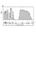
- FIG. 2 is a diagram showing the spectral reflectance of the rubber material used in this experiment. As shown in FIG. 2, the spectral characteristics of the infrared radiation materials 30a and 30b used in this experiment show a substantially flat spectral characteristic over 1 to 20 ⁇ m.
- the petri dish 40 was made of polystyrene.
- the spectral transmittance is shown in FIG. As shown in FIG. 3, the infrared rays of 5 ⁇ m or more are substantially blocked, and the transmittance is zero when it is 7.5 ⁇ m or more.
- FIG. 3 shows the spectral transmittance of the petri dish used in the experiment and the spectral transmittance of the flexible disk made of the same polystyrene material.
- the spectral transmittance of silicon (Si) is also shown.
- the spectral transmittance of silicon (Si) shows a substantially flat spectral characteristic. A filter using a silicon material will be described later.
- the petri dish 40 functions as a filter.
- infrared rays radiated from the infrared radiation materials 30a and 30b infrared rays larger than 7.5 ⁇ m are blocked by the petri dish 40, and the specimen 10 has 7.5 ⁇ m. Only the following infrared rays are irradiated.
- the temperature in the incubator in which the experimental apparatus shown in FIG. 1 was installed that is, the chamber of the culture tank was maintained at 37 ° C., and the carbon dioxide gas concentration was maintained at 5% as in the general culture experiment.
- the temperature of the culture solution 20 in the petri dish 40 slightly increased to 37.68 ° C. due to the addition of the cell growth heat of the specimen 10 when the infrared radiation materials 30a and 30b were installed.
- the temperature was 37.32 ° C. even when the cell growth heat of the specimen 10 was added.
- the experiment period is 28 days, the temperature in the incubator is always kept at 37 ° C., and the culture of the specimen 10 is continued for 21 days while the temperature of the specimen 10 is 37.68 ° C. Then, each cancer cell is put in the culture solution 20 in the petri dish 40 again, and further cultured for 7 days.
- the cancer cell is collected on the 29th day, and the number of living cancer cells is counted. did.
- the number of viable cells was examined by performing an XTT assay.
- the kit used is Cell Proliferation Kit II (Roche Diagnostics, Mannheim, Germany).
- FIG. 4 shows the experimental results.
- the graph shows the percentage increase in the number of cells on the 29th day as a percentage based on the number of cells on the 21st day.
- the cancer cells the number of cancer cells when the infrared radiation materials 30a and 30b are installed is statistically significantly reduced by 58.5% as compared with the case where the infrared radiation materials 30a and 30b are not installed. And 41.5%.
- normal cells human epithelial cells
- the number of normal cells when the infrared radiation materials 30a and 30b are installed is statistically significantly 69.compared with the case where the infrared radiation materials 30a and 30b are not installed. It increased by 5% to 169.5%.
- the reason why the gene repair circuit is activated is not simply that the temperature of the specimen 10 is maintained at 37.68 ° C., but infrared rays associated with cell growth are reflected by the infrared radiation materials 30a and 30b. It is considered that infrared rays having a wavelength greater than 7.5 ⁇ m were blocked, and infrared rays of 7.5 ⁇ m or less were irradiated on the specimen 10 and reached the deep part of the specimen 10.
- the petri dish 40 functions as a filter, and among infrared rays emitted from the infrared emitting materials 30a and 30b at 37.68 ° C., infrared rays having a wavelength greater than 7.5 ⁇ m It is blocked by the petri dish 40, and the specimen 10 is irradiated with only infrared rays having a wavelength of 7.5 ⁇ m or less.
- the infrared rays having a wavelength of 7.5 ⁇ m or less that have passed through the petri dish 40 pass through the air with a carbon dioxide concentration of 5% in the petri dish 40, and pass through the culture solution, the cell wall, and further the cytoplasm.
- the spectral transmittance due to carbon dioxide molecules is almost transmitted through infrared rays having a wavelength of 7.5 ⁇ m or less as shown in the partial absorption spectrum.
- there are innumerable minute holes of about 2 to 7 ⁇ m in the cell, such as pores on the mitochondrial surface it is considered that infrared rays having a wavelength smaller than the diameter of these holes enter the cytoplasm from the cell wall.
- the human body is composed of moisture.
- the spectral transmittance by water molecules shows that infrared rays having a wavelength of 7.5 ⁇ m or less are almost transmitted except for infrared rays having some wavelengths.
- infrared rays having a wavelength of 7.5 ⁇ m or less reach the deep part of the specimen 10 to activate the gene repair circuit and apoptotic circuit of the cancer cells of the specimen 10, and the number of cancer cells Is considered to have decreased.
- Bio Rubber registered trademark
- Biorubber used as an infrared radiation material in this experiment is usually used as an infrared reflective material to be worn on the human body.
- Biorubber registered trademark
- Biorubber is worn in the form of a wet suit or the like as a clothing material of the human body, and the infrared rays radiated from the human body are reflected back to the human body again.
- simply wearing the original Biorubber (registered trademark) on the human body will only receive infrared rays emitted from the human body with a body temperature of 36.5 ° C. and return to the human body side. Is lacking.
- FIG. 6 confirms the efficacy against human cancer cells in the case of a reflective configuration that receives the infrared rays radiated from the human body and reflects them to the human body side using Biorubber (registered trademark) without using the heat source part. It is a figure which shows the mode of experiment. Here, it experimented using the nude mouse. In this experimental example, filters for adjusting the wavelength of infrared rays are not provided.
- Biorubber registered trademark
- FIG. 6 Biorubber (registered trademark) is shown only on the upper surface of the gauge and is not shown on the other surfaces, but actually, the side and bottom surfaces are also covered with Biorubber (registered trademark). As shown in FIG.
- mice 300a and 300b transplanted with cancer cells are placed in separate gauges 200a and 200b, and the gauge 200a shown in the upper section is covered with Bio Rubber (registered trademark), which is an infrared radiation material 110.
- the infrared radiation material 110 is not provided around the gauge 200b shown in the lower part.
- nude mice 300a and 300b About 3 million human prostate cancer cells were transplanted subcutaneously into the back of nude mice 300a and 300b, and the size of tumor growth was observed. Since nude mice do not have T cells, rejection does not occur.
- the nude mouse 300a having a gauge 200a is constantly irradiated with infrared rays having a wavelength of 7.5 ⁇ m or less, but the nude mouse 300b having a gauge 200b is bred in a normal environment without being irradiated with infrared rays having a wavelength of 7.5 ⁇ m or less. Has been.
- the mouse 300a and the mouse 300b radiate infrared rays corresponding to the body temperature to the surroundings.
- the infrared ray emitting material 110 is provided on the gauge 200a side, the infrared rays are reflected, and the infrared ray is reflected from the infrared ray emitting material 110 to the mouse 300a. Will be returned again.
- the experiment was conducted for 93 days while keeping the temperature in the gauge at 23 ° C. and the humidity at 40%. The experimental results are shown in FIG. If human cancer cells are simply left unattended, they will continue to grow in the mouse, and the number of cells will increase. As shown in FIG.
- the cell activation device 100 of the present invention includes a heat source unit, devised so that the wavelength of infrared rays to be irradiated is 7.5 ⁇ m or less, and activates normal cells, resulting in abnormalities such as human cancer cells. The effect of suppressing cell proliferation is obtained as early as possible.
- the cell activation device of the present invention actively radiates infrared rays of 7.5 ⁇ m or less while using the infrared reflecting material 110, and constantly radiates infrared rays to the affected area,
- the gene repair circuit inherent to cells such as cancer cells is activated.
- the cell activation device of the present invention has a so-called human body non-contact type device configuration. Since conventional Biorubber (registered trademark) is applied to the human body, it is always worn 24 hours a day to radiate infrared rays to the affected area as in the above experiment. This is because it will deprive the patient of freedom of action.
- Biorubber registered trademark
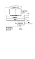
- FIG. 8 is a diagram schematically showing the basic configuration of the cell activation device 100 of the present invention.
- the cell activation device 100 of the present invention irradiates infrared rays having a wavelength of 7.5 ⁇ m or less.
- it is an infrared irradiation apparatus that irradiates infrared rays having a wavelength of 7.5 ⁇ m or less from the outside with a so-called non-contact type that is installed at a position away from the patient affected area.
- the cell activation device 100 includes an infrared radiation unit 110, a heat source unit 120, an infrared wavelength adjustment unit 130, and a temperature control circuit 140.
- the infrared radiation unit 110 is a material that radiates infrared rays, and radiates infrared rays according to temperature.
- the material is not particularly limited as long as the material emits infrared rays in proportion to the temperature.
- Bio Rubber registered trademark
- ceramics such as roof tiles, copper plates, and metal materials such as aluminum plates can be used.
- the heat source unit 120 generates heat and supplies heat to the infrared radiation unit 110.
- the heat source unit 120 is not particularly limited as long as its heat generation amount can be controlled, but for example, a heat source unit such as a planar heater that can control the temperature with current / voltage can be applied.
- the infrared wavelength adjusting unit 130 is an element that cuts infrared rays having a wavelength larger than 7.5 ⁇ m, which acts as heat rays, and transmits only infrared rays having a wavelength of 7.5 ⁇ m or less effective for cell activation.
- an optical filter is used.
- suitable materials for the filter include the aforementioned Biorubber (registered trademark), water, and polystyrene resin. In addition to water and polystyrene resin, there is no particular limitation as long as the material has a characteristic of cutting infrared light having a wavelength larger than 7.5 ⁇ m and allowing infrared light having a wavelength of 7.5 ⁇ m or less to pass.
- the temperature control circuit 140 is a circuit that accurately controls the temperature of the heat source unit 120.
- the temperature control circuit There are various circuit configurations of the temperature control circuit, but it is a known technique and is not particularly limited. In this example, in order to adjust the temperature by receiving the input voltage (AC 100 V), for example, a voltage control circuit is included.
- infrared rays having a wavelength greater than 7.5 ⁇ m that act as heat rays can be cut, and only infrared rays of 7.5 ⁇ m or less useful for cell activation can be irradiated toward the affected area. .
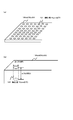
- FIG. 9 is a configuration example of a cell activation bed to which the principle of the cell activation device of the present invention is applied.
- a heat source, an infrared radiation material, and a filter are incorporated in the lower part of the bed, and an infrared ray of 7.5 ⁇ m or less is constantly irradiated from below the bed just by the patient sleeping on the bed. It has become.
- the heat source part is provided at the lower part of the bed, it is necessary to take sufficient heat dissipation measures so as not to accumulate heat.
- the heat source unit 120, the infrared radiation material 110, and the filter 130 are incorporated in the lower part of the bed.
- the heat source unit 120, the infrared radiation material 110, and the filter 130 are incorporated in a ceiling illuminating body, etc. It may be a type that emits infrared light having a wavelength of 7.5 ⁇ m or less from the overhead.
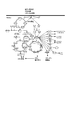
- FIG. 10 is a diagram schematically showing a gene repair mechanism.
- a cycle in which a gene is normally repaired in a cell in which the gene is damaged is schematically shown. If the gene repair circuit is activated, a damaged gene of a cancerous cell can be repaired and converted into a normal cell. On the other hand, in a state where human cancer cells grow, the gene repair mechanism inherent to the cells does not function well, and the cancer progresses because the human cancer cells repeat proliferation.
- the cell activation device 100 of the present invention activates this gene repair mechanism inherent in each cell, thereby returning a cell that has become cancerous to a normal cell, and a cell that has become cancerous. It promotes the apoptosis of human cancer cells by killing them. Moreover, the effect which protects the canceration of the normal cell around a cancer cell is also anticipated.
- the filter is used as a component that cuts infrared rays having a wavelength greater than 7.5 ⁇ m.
- the component that blocks infrared rays larger than 5 ⁇ m is not limited to an optical filter, and other components can be substituted.
- an example in which components other than the optical filter are substituted will be described.
- the surface of a resin plate, roof tile, or other member can be replaced with a material provided with pores having a size about twice the infrared wavelength to be cut.
- a member having a large number of pores on the surface has a property that a wavelength larger than about 1/2 of the pore diameter does not pass. If the pore diameter is about 15 ⁇ m, the cutoff frequency is Since the thickness is 7.5 ⁇ m, it is possible to exhibit a function equivalent to the filter characteristic of cutting infrared rays having a wavelength greater than 7.5 ⁇ m, and the filter can be replaced.
- FIG. 12 is a diagram schematically illustrating a basic configuration of the cell activation device 100a according to the second embodiment.
- the cell activation device 100a according to the second embodiment is an example including a ceramic 130a having a high infrared emissivity such as a roof tile having a large number of pores having a diameter of 15 ⁇ m on the surface. Note that a plate-like body other than the ceramic 130a can be applied as long as the pores can be processed.
- infrared rays radiated from the infrared radiation material 130a In the configuration of FIG. 12, among infrared rays radiated from the infrared radiation material 130a, only infrared rays having a wavelength of 7.5 ⁇ m or less pass through the plate, and infrared rays having a wavelength greater than 7.5 ⁇ m are blocked by the plate. . Infrared rays having a wavelength greater than 7.5 ⁇ m blocked by these plates re-emit infrared rays having a wavelength of 7.5 ⁇ m or less due to the action of temperature radiation, which helps to improve infrared radiation efficiency. In the configuration using this plate-like body, directivity can be given in the direction of infrared rays. FIG.
- FIG. 13 is a diagram schematically showing the relationship between the depth (d) and diameter (r) of the pores and the directivity of the reflected infrared rays. It is known that directivity occurs in the configuration in which pores are provided on the surface of ceramics 130a, which is an infrared radioactive material, depending on the relationship between the diameter and depth of the pores. That is, there is a property that the directivity in the axial direction of the pore increases as the depth of the pore becomes deeper than the diameter of the pore.
- FIG. 14 is a diagram schematically showing a quartz glass water filter 130b filled with water. Since quartz glass itself has a substantially constant spectral transmittance with respect to infrared rays having a wavelength of 1 to 10 ⁇ m, the performance of the quartz glass water filter 130b in which water is enclosed is determined by the spectral transmittance of water. Since water absorbs infrared rays having a wavelength greater than 7.5 ⁇ m and does not transmit it, but transmits infrared rays having a wavelength of 7.5 ⁇ m or less, the water filter 130b made of quartz glass encapsulating water has the infrared ray shown in Example 1.
- optical filter 130 It can be an alternative component of the optical filter 130 that is the wavelength adjusting unit.
- an optical filter that cuts an infrared ray having a wavelength of 10 ⁇ m or more.
- the cell activation device of the present invention can be widely used as a device for cell activation.
- it can be widely used to support cancer treatment, and a patient can support cancer treatment while living daily life.
Abstract
Description
このような現状を踏まえ、癌治療研究および癌治療用の機器開発は活発に行われているが、まだ決定的な癌治療方法は見出されていないのが現状である。
特許文献1では、頭部以外の全身を密閉収容するカプセル状の容器に患者を入れ、赤外線を照射して赤外線照射手段による輻射熱と密閉容器内の空気による伝導熱とによって患者の頭部以外のほぼ全身を加温し、患部の深部体温を短時間で41℃~42.5℃に到達させる技術が開示されている。
まず、特許文献1の技術では、全身または患部の深部体温を41℃~42℃程度に上げるためには血液を45℃~46℃に加温する必要があり、通常血液の凝固を防止する等のために例えばへパリン等を投与するため、治療時間は1時間程度が限度であり、治療後数日間は立ち上がれないほどの肉体的負担を生ずることである。
一方、正常細胞については生理的範囲である43℃以下に抑える必要があるため、正常細胞を保護しつつ患部体温を41℃~42℃に上げることは難しいという問題があった。
本発明の細胞活性化装置は、発明者島博基がさらに研究を進めて得た新たな知見をもとに開発したものであり、従来技術とは異なる構成により赤外線を細胞に照射することにより細胞本来が持つ遺伝子修復回路を活性化させるものである。
また、本発明の細胞活性化装置は、正常細胞を活性させることができるので、癌の予防のみならず、他の疾病の予防にも役立つ効能が認められる。
20 培養液
30 赤外線放射部
40 フィルター
100 細胞活性化装置
110 熱源部
120 赤外線放射部
130 赤外線波長調整部(光学フィルター)
130a セラミックス
130b 石英ガラス製水フィルター
140 温度制御回路
図1は、癌細胞検体を用いた7.5μm以下の波長の赤外線照射によるヒト癌細胞に対する効果を確認する実験の概要を示す図である。
図1(a)に示すように、シャーレ40内に検体10と培養液20を入れ、シャーレ40の上側に赤外線放射材料30aを配し,シャーレ40の下側にも赤外線反射材料30bを敷いたものを用意した。
図1(b)は、図1(a)に示した各構成の位置関係を示した縦断面図である。
培養液20は、一般的な培養液組成で良い。ここでは、ウシ胎仔血清、L-グルタミン、ペニシリンを含むアミノ酸液を用いた。
赤外線放射材料30a,30bは、赤外線を放射する素材であり、この実験では一例としてゴム製平板に微小な穴を開け、人体から放射される赤外線を反射する構造としたラバー素材(山本化学工業製:バイオラバー(登録商標))を用いた。図2は本実験に用いたラバー素材の分光反射率を示す図である。図2に示すように、本実験に用いた赤外線放射材料30a,30bの分光特性は1~20μmにわたってほぼフラットな分光特性を示すものとなっている。
図1に示した実験装置を設置したインキュベータ内即ち培養槽の庫内の温度を37℃に保ち、一般の培養実験と同様、炭酸ガス濃度を5%に保った。
実験期間は28日間行い、インキュベータ内の温度を常時37℃に保ち、検体10等の温度が37.68℃となった状態にて21日間検体10の培養を続けた後、生きている癌細胞を集めて数を勘定した後、各癌細胞を再びシャーレ40内の培養液20に入れて、さらに7日間培養した後に29日目に癌細胞を回収し、生きている癌細胞の数を勘定した。細胞増殖数はXTTアッセイを行って生細胞数を調べた。使用したキットはCell Proliferation Kit II (Roche Diagnostics, Mannheim, Germany)である。
実験の結果、癌細胞に関しては、赤外線放射材料30aおよび30bを設置しない場合に比較して、赤外線放射材料30aおよび30bを設置した場合の癌細胞数は統計学的に有意に58.5%減少し、41.5%となった。一方、正常細胞(ヒト上皮細胞)に関しては、赤外線放射材料30aおよび30bを設置しない場合に比較して、赤外線放射材料30aおよび30bを設置した場合の正常細胞数は統計学的に有意に69.5%増加し、169.5%となった。
本実験で赤外線放射材料として用いたバイオラバー(登録商標)は、通常、人体に被服する赤外線反射材料として用いられているものである。つまり、バイオラバー(登録商標)は人体の被服素材としてウェットスーツ等の形で装着し、人体から放射された赤外線を再び人体に反射帰還するものである。つまり、本来のバイオラバー(登録商標)を、人体に装着したのみでは体温36.5℃の人体から放射された赤外線を受けて人体側に帰還するだけのものとなり、輻射する赤外線において必要な強度が不足している。
図6に示すように、癌細胞を移植したマウス300a,300bを別々のゲージ200a,200bに入れ、上段に示したゲージ200aの周りには赤外線放射材料110であるバイオラバー(登録商標)で覆い、下段に示したゲージ200bの周りには赤外線放射材料110を設けない構成としている。
ゲージ内の温度を23℃、湿度を40%に保ち、93日間にわたり実験を行った。実験結果を図7に示す。ヒト癌細胞は単に放置しておくとマウス体内で増殖を繰り返すので細胞数は右肩上がりに増えて行く。図7に示すように、赤外線放射を行わないゲージ200bのマウス300bにおいてはヒト癌細胞の数は右肩上がりに増えて行っている。一方、赤外線が照射されているゲージ200aのマウス300bは当初はヒト癌細胞の数が右肩上がりに上がってゆくが、70日目を過ぎたあたりから有意に減少に転じている。この結果より、赤外線を照射することにより70日間程度という長期間を要するもののヒト癌細胞が有意に減少に転じる効能が得られることが分かる。
つまり、単に赤外線反射材料110であるバイオラバー(登録商標)を人体(マウス)に被服させて人体(マウス)から輻射される赤外線を反射するのみでは7.5μm以下の波長の赤外線の強度が不足しているため、ヒト癌細胞増殖を抑える効果が顕れるのが遅くなったことが分かる。
そこで、本発明の細胞活性化装置100は、熱源部を備え、照射する赤外線の波長を7.5μm以下となるように工夫し、正常細胞を活性化し、結果的にヒト癌細胞のような異常細胞の増殖を抑える効果をできるだけ早期に得るようにしたものである。
本発明の細胞活性化装置100は、図8に示すように、7.5μm以下の波長の赤外線を照射するものとなっている。また、患者患部とは離した位置に設置するいわゆる非接触タイプにて7.5μm以下の波長の赤外線を外部から照射する赤外線照射装置となっている。
赤外線放射部110は、前述したように、赤外線を放射する素材であり、温度に応じて赤外線を輻射するものである。素材としては温度に比例して赤外線を放射する材料であれば特に限定する必要はない。例えば前述したバイオラバー(登録商標)、瓦などのセラミックス、銅版、アルミニウム板などの金属材料が挙げられる。
なお、フィルターに熱がこもって温度が上昇しないようにフィルターを冷却する必要がある場合、ヒートシンクを用いた熱伝導放熱、媒体を用いた空冷や水冷、冷却材を用いた冷却など多様な方法が適用可能であり、このような冷却装置を搭載することができる。
温度制御回路の回路構成としては多様なものがあるが、公知技術であり、特に限定されない。この例では入力電圧(AC100V)を受けて温度を調整するため、例えば電圧制御回路を含むものである。
なお、図9ではベッドの下部に熱源部120と赤外線放射材料110とフィルター130が組み込まれた構成としたが、例えば、熱源部120と赤外線放射材料110とフィルター130を天井照明体などに組み込み、頭上から7.5μm以下の波長の赤外線に放射するタイプであっても良い。
癌が生じる原因には未解明の部分があるが、何らかの原因で遺伝子が傷ついてしまうことが挙げられる。人体の各細胞には、生来、自らの遺伝子が傷ついた場合に正常な遺伝子に戻すべく遺伝子修復機構を持っており、傷ついた遺伝子を修復する性質が備わっている。
一方、ヒト癌細胞が増殖してゆく状態は、その細胞が本来持っている遺伝子修復機構がうまく機能せず、ヒト癌細胞が増殖を繰り返すため癌が進行することとなる。
7.5μm以下の波長の赤外線照射を行いつつヒト癌細胞を28日間培養し、21日目に35mmの培養皿に細胞を移して観察した。図11(a)に示すように、これらの細胞の核をプロピジウムヨウ化物で染めた後TUNEL {Termi-nal deoxynucleotidyl transferase (TdT)-mediated deoxyuridine
triphosphate (dUTP)-digoxigenin nick end labeling (TUNEL) }染色を行いガン細胞のアポトーシスを蛍光顕微鏡で観察したところ、赤外線を照射された癌細胞において断片化した細胞(矢印)が認められアポトーシスが起こっていることがわかる。
なお、以上の細胞実験において、照射赤外線量について便宜的に温度を用いて説明してきたが、その理由は、温度が赤外線波長と振動数がもたらすエネルギー量に依存するからである。
実施例2の細胞活性化装置100aは、図12に示すように、表面に直径15μmの細孔が多数設けられた瓦などの赤外線放射率の高いセラミックス130aを備えた例となっている。なお、細孔の加工が可能であれば、セラミックス130a以外の板状体であっても適用することができる。
なお、この板状体を用いた構成において、赤外線の方向に指向性を持たせることが可能である。図13は、細孔の深さ(d)と径(r)と反射される赤外線の指向性との関係を模式的に示す図である。赤外線の放射性素材であるセラミックス130aの表面に細孔を設けた構成においてその細孔の径と深さの関係により指向性が生じることが知られている。つまり、細孔の径に比べて細孔の深さが深いほど細孔の軸方向への指向性が強まるという性質がある。この性質を利用すれば、本発明の細胞活性化装置のように、非接触で患者患部まで多少の距離(例えば数十センチから数メートル)があっても、有意な赤外線を非接触で患者の患部に照射することが可能となる。なお、上記の例ではセラミックスであったが、表面に所定径の細孔を穿つことのできる板状体であれば、ラバーなど多様な素材であっても採用することができる。
Claims (7)
- 癌細胞を含む患部に対して赤外線を照射せしめる細胞活性化装置であって、
熱源部と温度制御部と赤外線放射体部を備え、前記温度制御部を介して前記赤外線放射体部の輻射線の波長を制御し、前記赤外線放射体部から7.5μm以下の波長の赤外線のみを細胞に放射せしめる細胞活性化装置。 - 前記赤外線放射体部の表面に7.5μm以下の波長の赤外線のみを透過させるフィルターを備え、主に熱線として作用する7.5μmよりも大きな波長の赤外線を遮断し、7.5μm以下の波長の赤外線のみを前記細胞に照射する請求項1に記載の細胞活性化装置。
- 前記赤外線放射体部の表面に細孔が設けられ、細孔の径を15μm以下にすることにより、主に熱線として作用する7.5μmよりも大きな波長の赤外線を発生せず、7.5μm以下の波長の赤外線のみを前記細胞に照射せしめる請求項1または2に記載の細胞活性化装置。
- 前記赤外線放射体部の表面の前記細孔の深さを前記径よりも大きくし、前記赤外線放射体部からの放射線に指向性を持たせた構造としたことを特徴とする請求項3に記載の細胞活性化装置。
- 前記赤外線放射体部の表面に、石英ガラス製の容器でその内部に水を満たした水性フィルターである第1のフィルターと、主に熱線として作用する7.5μmよりも大きな波長の赤外線を遮断する第2のフィルターとを設けたことを特徴とする請求項2に記載の細胞活性化装置。
- 前記温度制御部により前記熱源部の温度分布を略一定に維持せしめることができる請求項1から5のいずれか1項に記載の細胞活性化装置。
- 前記温度制御部により、前記赤外線放射体部の表面温度を略一定に維持せしめることができる請求項1から6のいずれか1項に記載の細胞活性化装置。
Priority Applications (3)
| Application Number | Priority Date | Filing Date | Title |
|---|---|---|---|
| EP12773496.0A EP2700430A4 (en) | 2011-04-19 | 2012-04-18 | CELL ACTIVATION DEVICE |
| JP2013511012A JPWO2012144504A1 (ja) | 2011-04-19 | 2012-04-18 | 細胞活性化装置 |
| US14/112,705 US20140121733A1 (en) | 2011-04-19 | 2012-04-18 | Cell activation device |
Applications Claiming Priority (2)
| Application Number | Priority Date | Filing Date | Title |
|---|---|---|---|
| JP2011093524 | 2011-04-19 | ||
| JP2011-093524 | 2011-04-19 |
Publications (1)
| Publication Number | Publication Date |
|---|---|
| WO2012144504A1 true WO2012144504A1 (ja) | 2012-10-26 |
Family
ID=47041610
Family Applications (1)
| Application Number | Title | Priority Date | Filing Date |
|---|---|---|---|
| PCT/JP2012/060410 WO2012144504A1 (ja) | 2011-04-19 | 2012-04-18 | 細胞活性化装置 |
Country Status (4)
| Country | Link |
|---|---|
| US (1) | US20140121733A1 (ja) |
| EP (1) | EP2700430A4 (ja) |
| JP (1) | JPWO2012144504A1 (ja) |
| WO (1) | WO2012144504A1 (ja) |
Cited By (2)
| Publication number | Priority date | Publication date | Assignee | Title |
|---|---|---|---|---|
| JP5875131B1 (ja) * | 2014-11-13 | 2016-03-02 | 博基 島 | 細胞活性化装置 |
| JP2016213444A (ja) * | 2015-04-10 | 2016-12-15 | 東京エレクトロン株式会社 | イメージ反転、誘導自己組織化、および選択的堆積を補助するための、サブ解像度開口部の使用 |
Citations (4)
| Publication number | Priority date | Publication date | Assignee | Title |
|---|---|---|---|---|
| JPS61259680A (ja) * | 1985-05-14 | 1986-11-17 | 伊藤 義夫 | 赤外線集光によるガン温熱治療装置 |
| JPH1089588A (ja) * | 1996-09-11 | 1998-04-10 | Daikin Ind Ltd | 低温機器用輻射シールド |
| JP2004271518A (ja) * | 2003-02-17 | 2004-09-30 | Matsushita Electric Ind Co Ltd | ガスセンサーおよびガスセンサー用フィラメント |
| WO2010090287A1 (ja) * | 2009-02-06 | 2010-08-12 | キュテラ アイエヌシー. | 腫瘍治療装置 |
Family Cites Families (4)
| Publication number | Priority date | Publication date | Assignee | Title |
|---|---|---|---|---|
| US5973316A (en) * | 1997-07-08 | 1999-10-26 | Nec Research Institute, Inc. | Sub-wavelength aperture arrays with enhanced light transmission |
| KR20050026404A (ko) * | 2002-06-19 | 2005-03-15 | 팔로마 메디칼 테크놀로지스, 인코포레이티드 | 깊이로 조직을 광열 치료하기 위한 방법 및 장치 |
| US7722600B2 (en) * | 2003-08-25 | 2010-05-25 | Cutera, Inc. | System and method for heating skin using light to provide tissue treatment |
| MX2010009762A (es) * | 2008-03-07 | 2010-09-28 | Koninkl Philips Electronics Nv | Dispositivo de foto-depilacion. |
-
2012
- 2012-04-18 JP JP2013511012A patent/JPWO2012144504A1/ja active Pending
- 2012-04-18 US US14/112,705 patent/US20140121733A1/en not_active Abandoned
- 2012-04-18 WO PCT/JP2012/060410 patent/WO2012144504A1/ja active Application Filing
- 2012-04-18 EP EP12773496.0A patent/EP2700430A4/en not_active Withdrawn
Patent Citations (4)
| Publication number | Priority date | Publication date | Assignee | Title |
|---|---|---|---|---|
| JPS61259680A (ja) * | 1985-05-14 | 1986-11-17 | 伊藤 義夫 | 赤外線集光によるガン温熱治療装置 |
| JPH1089588A (ja) * | 1996-09-11 | 1998-04-10 | Daikin Ind Ltd | 低温機器用輻射シールド |
| JP2004271518A (ja) * | 2003-02-17 | 2004-09-30 | Matsushita Electric Ind Co Ltd | ガスセンサーおよびガスセンサー用フィラメント |
| WO2010090287A1 (ja) * | 2009-02-06 | 2010-08-12 | キュテラ アイエヌシー. | 腫瘍治療装置 |
Cited By (5)
| Publication number | Priority date | Publication date | Assignee | Title |
|---|---|---|---|---|
| JP5875131B1 (ja) * | 2014-11-13 | 2016-03-02 | 博基 島 | 細胞活性化装置 |
| WO2016076405A1 (ja) * | 2014-11-13 | 2016-05-19 | 博基 島 | 細胞活性化装置 |
| JP2016101478A (ja) * | 2014-11-13 | 2016-06-02 | 博基 島 | 細胞活性化装置 |
| JP2016213444A (ja) * | 2015-04-10 | 2016-12-15 | 東京エレクトロン株式会社 | イメージ反転、誘導自己組織化、および選択的堆積を補助するための、サブ解像度開口部の使用 |
| JP2020092274A (ja) * | 2015-04-10 | 2020-06-11 | 東京エレクトロン株式会社 | イメージ反転、誘導自己組織化、および選択的堆積を補助するための、サブ解像度開口部の使用 |
Also Published As
| Publication number | Publication date |
|---|---|
| US20140121733A1 (en) | 2014-05-01 |
| EP2700430A1 (en) | 2014-02-26 |
| EP2700430A4 (en) | 2014-12-17 |
| JPWO2012144504A1 (ja) | 2014-07-28 |
Similar Documents
| Publication | Publication Date | Title |
|---|---|---|
| ES2499395T3 (es) | Procedimientos para facilitar la regeneración | |
| WO2007067830A3 (en) | Radiation ablation tracking system | |
| CN102281917A (zh) | 软组织的光热治疗 | |
| IN2014MN00955A (ja) | ||
| Romanos et al. | Uncovering dental implants using a new thermo‐optically powered (TOP) technology with tissue air‐cooling | |
| WO2012144504A1 (ja) | 細胞活性化装置 | |
| Shen et al. | Photodisruption in biological tissues and single cells using femtosecond laser pulses | |
| Bredikhin et al. | Indirect laser surgery | |
| JP2011078541A (ja) | 細胞活性化装置 | |
| Tian et al. | In vitro anti-tumor effect of high-fluence low-power laser light on apoptosis of human colorectal cancer cells | |
| JP5875131B1 (ja) | 細胞活性化装置 | |
| Yoo et al. | Non-ablative fractional thulium laser irradiation suppresses early tumor growth | |
| Ritz et al. | Correlation of intrahepatic light and temperature distribution in laser-induced thermotherapy of liver tumors and liver tissue | |
| Li et al. | Computational investigation on thermal responses of blood vessels during laser treatment of port wine stain | |
| Liu et al. | Biophotonics in photomedicine | |
| Gu et al. | Cartilage reshaping | |
| Yang et al. | Brain lesion induced by 1319nm laser radiation | |
| Qian et al. | Focused ultrasound induces apoptosis in pancreatic cancer cells | |
| Belov et al. | Shock-wave destruction of tissues as a method for treatment of degenerative diseases in gynecology | |
| Filatova et al. | Impact of holmium fibre laser radiation on the spinal cord dura mater and adipose tissue∗ | |
| Tailor et al. | Advanced Perineural Invasion of a Cutaneous Squamous Cell Carcinoma Involving the Supraorbital, Supratrochlear and Optic Nerves | |
| Bianchi et al. | Two-dimensional temperature feedback control strategy for thermal ablation of biological tissue | |
| Kim et al. | Multi-Lens Array (MLA)-Assisted Power-Modulated Photothermal Therapy for Enhanced Cancer Treatment | |
| Avetisyan et al. | The modeling of local distribution of the temperature photo-induced by ensemble of nanoparticles | |
| GĂZDARU et al. | Laser radiation propagation and heat transfer into cells and tissues |
Legal Events
| Date | Code | Title | Description |
|---|---|---|---|
| 121 | Ep: the epo has been informed by wipo that ep was designated in this application |
Ref document number: 12773496 Country of ref document: EP Kind code of ref document: A1 |
|
| NENP | Non-entry into the national phase |
Ref country code: DE |
|
| WWE | Wipo information: entry into national phase |
Ref document number: 2012773496 Country of ref document: EP |
|
| WWE | Wipo information: entry into national phase |
Ref document number: 14112705 Country of ref document: US |
|
| ENP | Entry into the national phase |
Ref document number: 2013511012 Country of ref document: JP Kind code of ref document: A |