WO2012144385A1 - 燃料電池 - Google Patents
燃料電池 Download PDFInfo
- Publication number
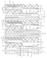
- WO2012144385A1 WO2012144385A1 PCT/JP2012/059873 JP2012059873W WO2012144385A1 WO 2012144385 A1 WO2012144385 A1 WO 2012144385A1 JP 2012059873 W JP2012059873 W JP 2012059873W WO 2012144385 A1 WO2012144385 A1 WO 2012144385A1
- Authority
- WO
- WIPO (PCT)
- Prior art keywords
- flow path
- separator
- oxidant gas
- cooling medium
- fuel
- Prior art date
- Legal status (The legal status is an assumption and is not a legal conclusion. Google has not performed a legal analysis and makes no representation as to the accuracy of the status listed.)
- Ceased
Links
Images






Classifications
-
- H—ELECTRICITY
- H01—ELECTRIC ELEMENTS
- H01M—PROCESSES OR MEANS, e.g. BATTERIES, FOR THE DIRECT CONVERSION OF CHEMICAL ENERGY INTO ELECTRICAL ENERGY
- H01M8/00—Fuel cells; Manufacture thereof
- H01M8/02—Details
- H01M8/0202—Collectors; Separators, e.g. bipolar separators; Interconnectors
- H01M8/0247—Collectors; Separators, e.g. bipolar separators; Interconnectors characterised by the form
-
- H—ELECTRICITY
- H01—ELECTRIC ELEMENTS
- H01M—PROCESSES OR MEANS, e.g. BATTERIES, FOR THE DIRECT CONVERSION OF CHEMICAL ENERGY INTO ELECTRICAL ENERGY
- H01M8/00—Fuel cells; Manufacture thereof
- H01M8/02—Details
- H01M8/0202—Collectors; Separators, e.g. bipolar separators; Interconnectors
- H01M8/0258—Collectors; Separators, e.g. bipolar separators; Interconnectors characterised by the configuration of channels, e.g. by the flow field of the reactant or coolant
-
- H—ELECTRICITY
- H01—ELECTRIC ELEMENTS
- H01M—PROCESSES OR MEANS, e.g. BATTERIES, FOR THE DIRECT CONVERSION OF CHEMICAL ENERGY INTO ELECTRICAL ENERGY
- H01M8/00—Fuel cells; Manufacture thereof
- H01M8/02—Details
- H01M8/0202—Collectors; Separators, e.g. bipolar separators; Interconnectors
- H01M8/0267—Collectors; Separators, e.g. bipolar separators; Interconnectors having heating or cooling means, e.g. heaters or coolant flow channels
-
- H—ELECTRICITY
- H01—ELECTRIC ELEMENTS
- H01M—PROCESSES OR MEANS, e.g. BATTERIES, FOR THE DIRECT CONVERSION OF CHEMICAL ENERGY INTO ELECTRICAL ENERGY
- H01M8/00—Fuel cells; Manufacture thereof
- H01M8/24—Grouping of fuel cells, e.g. stacking of fuel cells
- H01M8/241—Grouping of fuel cells, e.g. stacking of fuel cells with solid or matrix-supported electrolytes
-
- H—ELECTRICITY
- H01—ELECTRIC ELEMENTS
- H01M—PROCESSES OR MEANS, e.g. BATTERIES, FOR THE DIRECT CONVERSION OF CHEMICAL ENERGY INTO ELECTRICAL ENERGY
- H01M8/00—Fuel cells; Manufacture thereof
- H01M8/24—Grouping of fuel cells, e.g. stacking of fuel cells
- H01M8/2457—Grouping of fuel cells, e.g. stacking of fuel cells with both reactants being gaseous or vaporised
-
- Y—GENERAL TAGGING OF NEW TECHNOLOGICAL DEVELOPMENTS; GENERAL TAGGING OF CROSS-SECTIONAL TECHNOLOGIES SPANNING OVER SEVERAL SECTIONS OF THE IPC; TECHNICAL SUBJECTS COVERED BY FORMER USPC CROSS-REFERENCE ART COLLECTIONS [XRACs] AND DIGESTS
- Y02—TECHNOLOGIES OR APPLICATIONS FOR MITIGATION OR ADAPTATION AGAINST CLIMATE CHANGE
- Y02E—REDUCTION OF GREENHOUSE GAS [GHG] EMISSIONS, RELATED TO ENERGY GENERATION, TRANSMISSION OR DISTRIBUTION
- Y02E60/00—Enabling technologies; Technologies with a potential or indirect contribution to GHG emissions mitigation
- Y02E60/30—Hydrogen technology
- Y02E60/50—Fuel cells
Definitions
- the present invention relates to a fuel cell.
- MEAs membrane-electrode assemblies
- separators In solid polymer electrolyte fuel cells, membrane-electrode assemblies (MEAs) and separators are alternately arranged.
- the MEA includes an ion exchange electrolyte membrane, an anode (fuel electrode) disposed on one surface of the electrolyte membrane, and a cathode (oxygen electrode) disposed on the other surface of the electrolyte membrane.
- the separator forms fluid passages for supplying fuel gas (hydrogen) and oxidant gas (oxygen, usually air) to the anode and cathode, respectively.
- the fuel cell has a stack structure in which single cells (single cells) composed of MEAs and separators are stacked and integrated.
- a solid polymer electrolyte fuel cell has been attracting attention as a power source for a mobile body such as a vehicle because it has advantages such as being easily miniaturized and operating at a low temperature.
- This type of fuel cell is required to be reduced in size and cost for practical use.
- the cooling system and the humidification system can be simplified if the fuel cell can be operated under high temperature and no humidification.
- Patent Document 1 when the moisture amount in the vicinity of the inlet of the oxidant gas flow path that is most dry, that is, in the upstream portion is insufficient, the fuel gas flow rate is increased or the fuel gas pressure is decreased.
- a fuel cell that is configured to increase the amount of water in the vicinity of the inlet of the oxidant gas flow path and that can be operated under high temperature and no humidification.
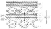
- Patent Document 2 discloses a fuel cell having a cross section as shown in FIG.
- Each unit cell 100 of the fuel cell includes a membrane electrode assembly (MEA) 108 and a pair of separators 110 and 112.
- the membrane electrode assembly 108 has a configuration in which a polymer electrolyte membrane 102 is sandwiched between a cathode (oxygen electrode) 104 and an anode (fuel electrode) 106.
- the separators 110 and 112 of each single cell 100 are disposed with the membrane electrode assembly 108 interposed therebetween.
- An oxidant gas flow path 114 is formed between the separator 110 and the cathode 104.
- a fuel gas channel 116 is formed between the separator 112 and the anode 106.
- the cathode 104 is formed by laminating a cathode catalyst layer 104a and a gas diffusion layer 104b.
- the anode 106 is formed by laminating an anode catalyst layer 106a and a gas diffusion layer 106b.
- Each separator 110, 112 has a plurality of grooves.
- the groove of the separator 110 of each single cell 100 is positioned to face the groove of the separator 112 of the single cell 110 adjacent to the single cell 100, and the cooling medium flow path 120 is formed by the grooves facing each other. Yes. Since the cooling medium flow path 120 is provided in the vicinity of the membrane electrode assembly 108, the fuel cell is efficiently cooled with a small thermal resistance by the cooling medium (for example, cooling water) flowing through the cooling medium flow path 120.
- the cooling medium for example, cooling water
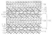
- Patent Document 3 discloses a fuel cell having a cross section as shown in FIG. In FIG. 13, components corresponding to those of the fuel cell of FIG. In the fuel cell of FIG. 13, the gas diffusion porous bodies 130 and 140 are provided with the fuel gas passage 116 and the oxidant gas flow in order to uniformly diffuse the gas throughout each of the fuel gas passage 116 and the oxidant gas passage 114. Each of the channels 114 is provided to improve the performance of the fuel cell.
- a water-conducting layer is provided on the gas diffusion porous body in order to improve the drainage of water generated by the fuel cell.
- the fuel cells described in Patent Document 1 and Patent Document 2 have high cooling performance, they are excellent in high temperature performance.
- the drainage and gas diffusibility in the vicinity of the outlet of the oxidant gas flow path with a large amount of water, that is, the downstream portion are poor. Therefore, there is a problem that the operation performance is low in a region where the load of the fuel cell is not so high, that is, in a normal temperature range where the cell temperature is about 50 to about 60 ° C.
- the fuel cell generates power in the normal temperature range when traveling at a cruising speed.
- Patent Document 3 Although the fuel cell described in Patent Document 3 is excellent in voltage stability particularly in a normal temperature range, it has a tendency to lack cooling performance in a high temperature environment due to its large thermal resistance. Therefore, there is a problem that the high temperature performance is not high.
- the oxidant gas flow path 114 and the fuel gas flow path 116 are formed by grooves provided on the entire surfaces of the separators 110 and 112, or the membrane electrode assembly 108 of the membrane electrode assembly 108 is formed as shown in FIG.
- the gas diffusion porous bodies 130 and 140 are arranged so as to correspond to the entire surface, the anode (fuel electrode) and the cathode (oxygen electrode) can be cooled uniformly.
- the cathode portion located in the vicinity of the inlet (upstream portion) of the oxidant gas flow path cannot be actively cooled, so that there is a problem that the high temperature performance is inferior.
- an object of the present invention is to improve the high temperature performance, the operation performance under high temperature and no humidification, and the power generation performance, and further, the drainage and gas in the downstream portion of the oxidant gas flow path having a particularly high water content.
- An object of the present invention is to provide a fuel cell capable of improving diffusibility and improving voltage stability in a normal temperature range.
- a fuel cell having a plurality of stacked single cells includes a membrane electrode assembly in which electrodes are arranged on both surfaces of a solid polymer electrolyte membrane, and a first separator and a second separator that are arranged with the membrane electrode assembly interposed therebetween.
- An oxidant gas flow path is formed between the first separator of each single cell and the membrane electrode assembly.
- a fuel gas flow path is formed between the second separator of each single cell and the membrane electrode assembly. The direction in which the oxidant gas flows through the oxidant gas flow path of each single cell faces the direction in which the fuel gas flows through the fuel gas flow path of the same single cell.
- Each oxidizing gas channel has an upstream portion and a downstream portion with respect to the direction in which the oxidizing gas flows through the oxidizing gas channel.
- the upstream portion of the oxidant gas channel is configured as a plurality of groove channels independent from each other by providing a plurality of first grooves on the surface of the first separator facing the membrane electrode assembly of each single cell. ing.
- a first gas diffusion porous body is disposed in the downstream portion of each oxidant gas flow path.
- Each fuel gas passage has an upstream portion and a downstream portion with respect to the direction in which the fuel gas flows through the fuel gas passage.
- the upstream portion of the fuel gas channel is configured as a plurality of groove channels independent from each other by providing a plurality of second grooves on the surface of the second separator facing the membrane electrode assembly of each single cell.
- a second gas diffusion porous body is disposed in the downstream portion of each fuel gas flow path.
- a cooling medium flow path is formed between the first separator of each single cell and the second separator of the single cell adjacent to the single cell. The direction in which the cooling medium flows through the cooling medium flow paths between the single cells adjacent to each other is the same as the direction in which the oxidizing gas flows through the oxidant gas flow paths of those single cells.
- Each cooling medium flow path has an upstream portion and a downstream portion with respect to the direction in which the cooling medium flows through the cooling medium flow path.
- the upstream portion of each cooling medium flow path is located closer to the surface of the membrane electrode assembly facing the oxidant gas flow path adjacent to the cooling medium flow path than the downstream portion of the same cooling medium flow path. .
- a fuel cell having a plurality of stacked single cells includes a membrane electrode assembly in which electrodes are arranged on both surfaces of a solid polymer electrolyte membrane, and a first separator and a second separator that are arranged with the membrane electrode assembly interposed therebetween.
- An oxidant gas flow path is formed between the first separator of each single cell and the membrane electrode assembly.
- a fuel gas flow path is formed between the second separator of each single cell and the membrane electrode assembly. The direction in which the oxidant gas flows through the oxidant gas flow path of each single cell faces the direction in which the fuel gas flows through the fuel gas flow path of the same single cell.
- Each oxidizing gas channel has an upstream portion and a downstream portion with respect to the direction in which the oxidizing gas flows through the oxidizing gas channel.
- the upstream portion of the oxidant gas channel is configured as a plurality of groove channels independent from each other by providing a plurality of first grooves on the surface of the first separator facing the membrane electrode assembly of each single cell. ing.
- a first gas diffusion porous body is disposed in the downstream portion of each oxidant gas flow path.
- Each fuel gas passage has an upstream portion and a downstream portion with respect to the direction in which the fuel gas flows through the fuel gas passage.
- a plurality of second grooves are provided on the surface of the second separator facing the membrane electrode assembly of each single cell.
- a second gas diffusion porous body is disposed in the downstream portion and the upstream portion of each fuel gas flow path.
- a cooling medium flow path is formed between the first separator of each single cell and the second separator of the single cell adjacent to the single cell.
- the direction in which the cooling medium flows through the cooling medium flow paths between the single cells adjacent to each other is the same as the direction in which the oxidizing gas flows through the oxidant gas flow paths of those single cells.
- Each cooling medium flow path has an upstream portion and a downstream portion with respect to the direction in which the cooling medium flows through the cooling medium flow path.
- the upstream portion of each cooling medium flow path is located closer to the surface of the membrane electrode assembly facing the oxidant gas flow path adjacent to the cooling medium flow path than the downstream portion of the same cooling medium flow path. .
- a fuel cell having a plurality of stacked single cells includes a membrane electrode assembly in which electrodes are arranged on both surfaces of a solid polymer electrolyte membrane, and a first separator and a second separator that are arranged with the membrane electrode assembly interposed therebetween.
- An oxidant gas flow path is formed between the first separator of each single cell and the membrane electrode assembly.
- a fuel gas flow path is formed between the second separator of each single cell and the membrane electrode assembly.
- the direction in which the oxidant gas flows in the oxidant gas flow path of each single cell is the same as the direction in which the fuel gas flows in the fuel gas flow path of the same single cell.
- Each oxidizing gas channel has an upstream portion and a downstream portion with respect to the direction in which the oxidizing gas flows through the oxidizing gas channel.
- the upstream portion of the oxidant gas channel is configured as a plurality of groove channels independent from each other by providing a plurality of first grooves on the surface of the first separator facing the membrane electrode assembly of each single cell. ing.
- a first gas diffusion porous body is disposed in the downstream portion of each oxidant gas flow path.
- Each fuel gas passage has an upstream portion and a downstream portion with respect to the direction in which the fuel gas flows through the fuel gas passage.
- a second gas diffusion porous body is disposed in the downstream portion and the upstream portion of each fuel gas flow path.
- a cooling medium flow path is formed between the first separator of each single cell and the second separator of the single cell adjacent to the single cell.
- the direction in which the cooling medium flows through the cooling medium flow paths between the single cells adjacent to each other is the same as the direction in which the oxidizing gas flows through the oxidant gas flow paths of those single cells.
- Each cooling medium flow path has an upstream portion and a downstream portion with respect to the direction in which the cooling medium flows through the cooling medium flow path.
- the upstream portion of each cooling medium flow path is located closer to the surface of the membrane electrode assembly facing the oxidant gas flow path adjacent to the cooling medium flow path than the downstream portion of the same cooling medium flow path. .
- the first separator of each single cell may contact the membrane electrode assembly of the same single cell at a portion corresponding to the upstream portion of the cooling medium flow path.
- water in the oxidant gas flow path is passed from the oxidant gas flow path between the first separator of each single cell and the first gas diffusion porous body.
- a first water flow path for discharging may be provided. As the oxidant gas flows through the oxidant gas channel, the water in the first water channel moves through the gap in the same direction as the direction in which the oxidant gas flows and is discharged from the oxidant gas channel. Is done.
- water in the fuel gas channel is discharged from the fuel gas channel between the second separator of each single cell and the second gas diffusion porous body.
- a second water flow path may be provided. As the fuel gas flows through the fuel gas channel, the water in the second water channel moves through the gap in the same direction as the direction in which the fuel gas flows and is discharged from the fuel gas channel.
- the present invention it is possible to improve the high-temperature performance, the operation performance under high-temperature non-humidification, and the power generation performance.
- the voltage stability in the normal temperature range can be improved.
- the oxidant is generated by the cooling medium flowing through the cooling medium flow path. It is possible to efficiently cool the upstream portion of the gas flow path, and it is possible to further improve the high temperature performance, the operation performance under high temperature and no humidification, and the power generation performance.
- the fuel channel for discharging the water in the fuel gas channel from the fuel gas channel is provided between the second separator of each single cell and the second gas diffusion porous body, the fuel The drainage performance of the gas channel is improved, and as a result, the power generation efficiency of the fuel cell is improved.
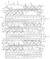
- the disassembled perspective view which shows a part of fuel cell of 1st Embodiment of this invention.
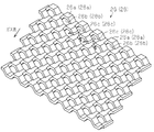
- the perspective view of the gas diffusion porous body of the fuel cell shown in FIG. FIG. 2 is a transverse cross-sectional view of the fuel cell shown in FIG.
- FIG. 2 is an overall schematic diagram of the fuel cell shown in FIG. 1.
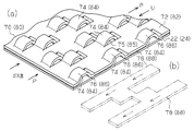
- FIG. 7A is a perspective view showing a part of a gas diffusion porous body of a fuel cell according to a second embodiment of the present invention, and FIG. 7B is provided between the gas diffusion porous body of FIG. 7A and a separator.
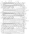
- Sectional drawing which shows a part of single cell of the fuel cell of 2nd Embodiment.
- the fuel cell 10 has a stack structure in which a large number of single cells 12 (see FIG. 2) are stacked.
- the stacked unit cells 12 are disposed between a pair of current collector plates 11.
- the two current collector plates 11 are disposed between the pair of insulating plates 13.
- the two insulating plates 13 are disposed between the pair of end plates 15.
- the single cell 12, the current collector plate 11 and the insulating plate 13 are sandwiched between the two end plates 15 by tightening with the tightening bolts 17.
- the fuel cell 10 is connected to an oxidant gas pipeline system, a fuel gas pipeline system, and a cooling medium pipeline system.
- the oxidant gas pipeline system is for supplying and discharging air (oxygen) as an oxidant gas to and from the fuel cell 10, and as shown in FIG.
- An oxidant gas supply pipe 51 connected to the gas supply port and an oxidant gas discharge pipe 52 connected to an oxidant gas discharge port (not shown) of the fuel cell 10 are provided.
- the fuel gas line system is for supplying and discharging hydrogen as fuel gas to and from the fuel cell 10, and includes a fuel gas supply pipe 54 connected to a fuel gas supply port (not shown) of the fuel cell 10, and And a fuel gas discharge pipe 56 connected to a fuel gas discharge port (not shown) of the fuel cell 10.
- the cooling medium conduit system is for supplying and discharging water as a cooling medium to and from the fuel cell 10, and includes a cooling medium supply pipe 58 connected to a cooling medium supply port (not shown) of the fuel cell 10. And a coolant discharge pipe 60 connected to a coolant discharge port (not shown) of the fuel cell 10.
- each single cell 12 includes a membrane electrode assembly (MEA) 20 in which a solid polymer electrolyte membrane 14 is provided between an anode 16 and a cathode 18.
- the MEA 20 is disposed between the first separator 22 and the second separator 24.
- a first gas diffusion porous body 26 is disposed between the first separator 22 and the MEA 20.
- a second gas diffusion porous body 28 is disposed between the second separator 24 and the MEA 20.
- an anode 16 that is a fuel electrode is disposed on one surface of the electrolyte membrane 14, and a cathode 18 that is an oxygen electrode is disposed on the other surface of the electrolyte membrane 14.
- the electrolyte membrane 14 is made of a solid polymer material having good proton conductivity in a wet state.
- a solid polymer material there is a fluorine polymer film (for example, Nafion film manufactured by DuPont).
- the anode 16 includes an electrode catalyst layer 16a and a gas diffusion layer 16b.
- the cathode 18 includes an electrode catalyst layer 18a and a gas diffusion layer 18b.
- the electrode catalyst layers 16a and 18a are in contact with the electrolyte membrane 14, and are formed of conductive carbon black carrying platinum fine particles.
- the gas diffusion layers 16b and 18b are laminated on the electrode catalyst layers 16a and 18a, and are made of conductive carbon paper. Platinum contained in the electrode catalyst layers 16a and 18a promotes the separation of hydrogen into protons and electrons and the reaction of generating water from oxygen, protons and electrons. A catalyst that performs the same function may be used in place of platinum.
- the gas diffusion layers 16b and 18b may be formed of a material other than carbon paper as long as it has sufficient gas diffusibility and conductivity.
- the gas diffusion layers 16b and 18b are formed of carbon cloth or carbon felt made of carbon fiber. May be.
- the first separator 22 is made of titanium and has conductivity. However, the material of the first separator 22 is not limited to titanium. You may form the 1st separator 22 from the carbon-type or metal-type other material which has electroconductivity. As shown in FIG. 2, an oxidant gas flow path 30 is formed between the first separator 22 and the MEA 20 of each single cell 12. The oxidant gas flow path 30 is connected to the oxidant gas supply port and the oxidant gas discharge port provided in the fuel cell 10 via a manifold hole (not shown).
- each first separator 22 includes a large flat plate portion 32 positioned on the downstream side of the oxidant gas flow channel 30 and a small flat plate portion positioned on the upstream side of the oxidant gas flow channel 30. 34.
- the two flat plate portions 32 and 34 of each first separator 22 are parallel to each other and are integrally connected to each other by a step portion 33.
- the large flat plate portion 32 of the first separator 22 of each unit cell 12 is substantially intermediate between the MEA 20 of the unit cell 12 and the MEA 20 of the unit cell 12 adjacent to the unit cell 12. Is located.
- the small flat plate portion 34 of each first separator 22 has the same length in the direction in which the oxidant gas flows through the oxidant gas flow path 30, that is, in the first direction indicated by the broken arrow U in FIG. It is shorter than that of the large flat plate portion 32 of one separator 22.
- the step portion 33 is inclined with respect to the first direction U.
- each first separator 22 is provided with a plurality of protrusions 35 extending in parallel with the first direction U.
- the protrusion 35 of the first separator 22 of each single cell 12 is formed so as to protrude toward the MEA 20 of the same single cell 12 by die press molding.
- the protrusion 35 of each first separator 22 extends from the approximate center of the large flat plate portion 32 in the first direction U across the step portion 33 to the approximate center of the small flat plate portion 34 in the first direction U. Yes.
- the adjacent ridges 35 of the first separators 22 are preferably arranged at an equal pitch, but may be at an unequal pitch depending on the case.
- the first separator 22 of each single cell 12 has a surface opposite to the surface facing the MEA 20 of the single cell 12, as shown in FIG. A plurality of grooves 36 extending in parallel with the first direction U are provided. Further, a first groove 35b is formed between the adjacent protrusions 35 of each first separator 22 as shown in FIGS.
- Each protrusion 35 facing the MEA 20 is formed as a flat wall portion 35a as shown in FIGS. 1 and 5, and an upstream portion of the oxidant gas flow path 30 as shown in FIGS. And close to the cathode 18 (gas diffusion layer 18b) of the MEA 20.
- each oxidant gas flow channel 30 is configured as a plurality of independent groove channels by providing a plurality of first grooves 35 b on the surface of the first separator 22 facing the MEA 20. Yes.
- a first gas diffusion porous body 26 is disposed in the downstream portion of each oxidant gas flow path 30.
- the second separator 24 is made of titanium and has conductivity.
- the material of the second separator 24 is not limited to titanium. You may form the 2nd separator 24 from the carbon-type or metal-type other material which has electroconductivity.
- a fuel gas flow path 40 is formed between the second separator 24 of each single cell 12 and the MEA 20.
- the direction in which the oxidant gas flows through the oxidant gas passage 30 and the direction in which the fuel gas flows through the fuel gas passage 40 are opposed to each other. That is, the oxidant gas and the fuel gas flow so as to face each other.
- the fuel gas channel 40 is connected to the fuel gas supply port and the fuel gas discharge port provided in the fuel cell 10 through a manifold hole (not shown).
- each second separator 24 includes a large flat plate portion 42 located on the downstream side of the fuel gas flow channel 40, and a small flat plate portion 44 located on the upstream side of the fuel gas flow channel 40.
- the two flat plate portions 42 and 44 of each second separator 24 are parallel to each other and are integrally connected to each other by a step portion 43.
- the large flat plate portion 42 of the second separator 24 of each single cell 12 is substantially intermediate between the MEA 20 of the single cell 12 and the MEA 20 of the single cell 12 adjacent to the single cell 12. Is located.
- each second separator 24 has the same length in the direction in which the fuel gas flows through the fuel gas flow path 40, that is, in the second direction indicated by the dashed arrow P in FIG. It is shorter than that of the large flat plate portion 42 of the separator 24.
- the step portion 43 is inclined with respect to the second direction P. In the present embodiment, the second direction P is 180 degrees opposite to the first direction U.
- each second separator 24 is provided with a plurality of protrusions 45 extending in parallel with the second direction P.
- the number and pitch of the ridges 45 provided on each second separator 24 are the same as the number and pitch of the ridges 35 provided on each first separator 22.
- the first separator 22 and the second separator 24 are arranged so that the ridges 35 and the ridges 45 are aligned with each other.
- the protrusion 45 of the second separator 24 of each single cell 12 is formed so as to protrude toward the MEA 20 of the same single cell 12 by die press molding.
- the protrusion 45 of each second separator 24 extends from the approximate center of the large flat plate portion 42 in the second direction P across the step portion 43 to the approximate center of the small flat plate portion 44 in the second direction P. Yes.
- the second separator 24 of each single cell 12 is on the surface opposite to the surface facing the MEA 20 of the single cell 12, as shown in FIG.
- a plurality of grooves 46 extending in parallel with the second direction P are provided.
- a second groove 45b is formed between the adjacent protrusions 45 of each second separator 24 as shown in FIG.
- the portions of the protrusions 45 facing the MEA 20 are formed as flat wall portions 45a as shown in FIGS. 2 and 3, and the anode 16 (gas diffusion layer 16b) of the MEA 20 is formed upstream of the fuel gas flow path 40. )
- each fuel gas channel 40 is configured as a plurality of groove channels independent from each other by providing a plurality of second grooves 45 b on the surface of the second separator 24 facing the MEA 20. .
- a second gas diffusion porous body 28 is disposed in the downstream portion of each fuel gas flow path 40.
- the large flat plate portion 42 of the second separator 24 of each single cell 12 is in close contact with the large flat plate portion 32 of the first separator 22 of the single cell 12 adjacent to the single cell 12. Are electrically connected.
- groove 46 of the second separator 24 of each single cell 12 is a portion indicated by symbol A in FIG. 3 with respect to the groove 36 of the first separator 22 of the single cell 12 adjacent to the single cell 12. Overlapping and communicating.
- the cooling medium flow path 50 More specifically, the first separator 22 of each single cell 12 and the second separator 24 of the single cell 12 adjacent to the single cell 12, more specifically, the groove 36 and the second provided in the first separator 22.
- the cooling medium flow path 50 is formed by the groove 46 provided in the separator 24.
- a gap between the small flat plate portion 34 of the first separator 22 and the large flat plate portion 42 of the second separator 24 functions as an inlet of the cooling medium flow path 50, and the small flat plate portion of the second separator 24.
- a gap between 44 and the large flat plate portion 32 of the first separator 22 functions as an outlet of the cooling medium flow path 50.
- each cooling medium flow path 50 that is, the groove 36
- the downstream portion of the cooling medium flow path 50 that is, the groove 46
- the oxidant gas flow adjacent to the cooling medium flow path 50 Located close to the surface of the MEA 20 facing the path 30.
- the upstream portion of each cooling medium flow path 50 is connected to the MEA 20 of the single cell 12 including the first separator 22 among the first and second separators 22 and 24 forming the cooling medium flow path 50. Located close together.
- each cooling medium flow path 50 that is, the groove 46
- the upstream portion of the cooling medium flow path 50 that is, the groove 36
- the MEA 20 that faces the fuel gas flow path 40 adjacent to the cooling medium flow path 50.
- the downstream portion of each cooling medium flow path 50 is connected to the MEA 20 of the single cell 12 including the second separator 24 among the first and second separators 22 and 24 forming the cooling medium flow path 50. Located close together.
- the cooling medium flow path 50 is connected to the cooling medium supply port and the cooling medium discharge port provided in the fuel cell 10 through a manifold hole (not shown).
- the direction in which the cooling medium such as cooling water flows through the cooling medium flow path 50 as indicated by the dashed arrow S in FIG. 3 is the same as the direction in which the oxidizing gas flows through the oxidant gas flow path 30. That is, the cooling medium and the oxidant gas flow in a parallel flow (coflow).
- the cooling medium flow path 50 is formed as described above, the portion of the cathode 18 located in the upstream portion of the oxidant gas flow path 30 is efficiently cooled in the upstream portion of the cooling medium flow path 50.
- the portion of the anode 16 located in the upstream portion of the fuel gas flow path 40 is efficiently cooled.
- the cathode 18 and the anode 16 are not uniformly cooled as a whole as described above, but the portion of the cathode 19 located in the vicinity of the inlet of the oxidant gas flow path 30 that is most easily dried, that is, in the upstream portion. Can be actively cooled.
- FIG. 4 is a perspective view showing a part of the first gas diffusion porous body 26, and the second gas diffusion porous body 28 has the same configuration as the first gas diffusion porous body 26.
- each gas diffusion porous body 26, 28 is formed of a lath cut metal in which a large number of hexagonal ring portions 26a, 28a are provided in a staggered manner.
- Each of the gas diffusion porous bodies 26 and 28 includes the oxidant gas flow path 30 so that the axis of the through holes 26b and 28b of the ring portions 26a and 28a extends so as to intersect the first direction U or the second direction P. Alternatively, it is arranged in the fuel gas flow path 40.
- the oxidant gas or the fuel gas passes through the gas passages 26c and 28c of the gas diffusion porous bodies 26 and 28, which are the through holes 26b and 28b of the ring portions 26a and 28a, so that the oxidant gas or the fuel gas becomes the oxidant gas passage 30 or the fuel. It is diffused in the gas flow path 40.
- the first gas diffusion porous body 26 of each single cell 12 is in contact with the cathode 18 and the first separator 22 of the same single cell 12 to electrically connect them.
- the second gas diffusion porous body 28 of each single cell 12 is in contact with the anode 16 and the second separator 24 of the same single cell 12 to electrically connect them.
- the oxidant gas flow path 30 and the fuel gas flow path 40 are respectively supplied with oxidant gas (air in this embodiment) and fuel gas (hydrogen gas in this embodiment). It passes so that it may become counterflow mutually. Further, the cooling medium (cooling water in the present embodiment) passes through the cooling medium flow path 50 in the same direction as the direction in which the oxidizing gas flows through the oxidizing gas flow path 30.
- the cooling medium enters the cooling medium flow path 50 through a gap between the small flat plate portion 34 of the first separator 22 and the large flat plate portion 42 of the second separator 24, and first forms a groove. Pass through 36. By passing the cooling medium through the groove 36, the portion of the cathode 18 located in the upstream portion of the oxidant gas flow path 30 is cooled via the wall portion 35a.
- An arrow Q in FIG. 3 indicates the direction of heat transfer from the cathode 18.
- the cooling medium passes through the groove 46.
- the portion of the anode 16 located in the upstream portion of the fuel gas flow path 40 is cooled via the wall 45a.
- An arrow R in FIG. 3 indicates the direction of heat transfer from the anode 16.
- the cooling medium exits from the cooling medium flow path 50 through a gap between the small flat plate portion 44 of the second separator 24 and the large flat plate portion 32 of the first separator 22.
- the portion of the cathode 18 positioned in the upstream portion of the oxidant gas flow path 30 is more actively cooled than the portion of the cathode 18 positioned in the downstream portion of the oxidant gas flow path 30.
- the portion of the anode 16 positioned in the upstream portion of the fuel gas flow path 40 is more actively cooled than the portion of the anode 16 positioned in the downstream portion of the fuel gas flow path 40.
- the deviation of moisture distribution in the plane of each single cell 12 of the fuel cell 10 Is likely to occur. More specifically, the vicinity of the inlet (upstream part) of the oxidant gas flow path 30 tends to be in a dry state, and the vicinity of the outlet of the oxidant gas flow path 30 (downstream part) tends to be in a wet state. For this reason, it is necessary to make the water content uniform in the plane of each single cell 12.
- the high temperature performance of the fuel cell 10 is improved by actively cooling the vicinity (upstream portion) of the inlet of the oxidant gas flow path 30.
- the oxygen concentration decreases with the consumption of oxygen in the oxidant gas by power generation, and water is generated by the reaction on the cathode 18.
- This generated water is discharged out of the oxidant gas flow path 30 by the oxidant gas (oxidant off-gas) flowing through the oxidant gas flow path 30 through the gas flow path 26c of the first gas diffusion porous body 26.
- the first gas diffusion porous body 26 is arranged in the downstream portion of the oxidant gas flow path 30, the inhibition of gas diffusion in the gas diffusion layer 18b by the generated water is suppressed.
- the power generation performance of the fuel cell 10 is improved.
- the drainage property of the downstream part of the oxidizing gas channel 30 is improved, the voltage stability in the normal temperature region is improved.
- a part of the generated water permeates the electrolyte membrane 14 and permeates the electrode catalyst layer 16 a and the gas diffusion layer 16 b of the anode 16 and the second gas diffusion porous body 28 of the fuel gas channel 40.
- This permeated water is discharged out of the fuel gas channel 40 by the fuel gas (fuel offgas) flowing through the fuel gas channel 40 through the gas channel 28 c of the second gas diffusion porous body 28.
- This embodiment has the following effects.
- the oxidant gas flow channel 30 has an upstream portion configured as a plurality of groove flow channels and a downstream portion where the gas diffusion porous body 26 is disposed.
- the fuel gas flow path 40 has an upstream portion configured as a plurality of groove flow paths, and a downstream portion where the gas diffusion porous body 28 is disposed.
- a cooling medium flow path 50 is formed between the first separator 22 of each single cell 12 and the second separator 24 of the single cell 12 adjacent to the single cell 12. The direction in which the cooling medium flows in the cooling medium flow path 50 is the same as the direction in which the oxidizing gas flows in the oxidant gas flow path 30.
- the upstream portion of the cooling medium flow path 50 is located closer to the surface of the MEA 20 facing the oxidant gas flow path adjacent to the cooling medium flow path 50 than the downstream portion of the cooling medium flow path 50. Therefore, according to the fuel cell 10 of the present embodiment, high-temperature performance, operation performance under high temperature and no humidification, and power generation performance are improved. Moreover, since the drainage property and gas diffusibility of the downstream part of the oxidant gas flow path with a particularly large amount of water are good, the voltage stability in the normal temperature region is improved. As a result of improving the operating performance and power generation performance under high temperature and no humidification, the fuel cell 10 can be reduced in size and cost.
- the gas diffusion porous bodies 26 and 28 are disposed only in the respective downstream portions of the oxidant gas passage 30 and the fuel gas passage 40. Therefore, the weight of the fuel cell 10 can be reduced as compared with the case where the gas diffusion porous body is disposed so as to correspond to the entire surfaces of the anode 16 and the cathode 18.
- the first separator 22 of each single cell 12 is in contact with the cathode 18 of the MEA 20 of the same single cell 12 at a portion corresponding to the upstream portion of the cooling medium flow path 50. ing. Therefore, the upstream part of the oxidant gas flow path 30 can be efficiently cooled by the cooling medium flowing through the cooling medium flow path 50, and further improvement in high temperature performance, operating performance under high temperature and no humidification, and power generation performance. Is possible.
- FIG. 7A The fuel cell according to the second embodiment includes first and second gas diffusion porous bodies 70 and 80 shown in FIG. 7A instead of the first and second gas diffusion porous bodies 26 and 28 shown in FIG. It is different from the fuel cell 10 of the first embodiment in that it is used.
- the configuration of the fuel cell of the second embodiment that is the same as or corresponding to the configuration of the fuel cell 10 of the first embodiment (except for the first and second gas diffusion porous bodies 70 and 80) is the first implementation.
- the same reference numerals as those used in the description of the embodiment are given.
- the first and second gas diffusion porous bodies 70, 80 include flat plate portions 72, 82 having a large number of cut-and-raised portions having a substantially S-shaped cross section. Each cut and raised portion is formed integrally with the flat plate portions 72 and 82, and forms first protrusions 74 and 84 and second protrusions 76 and 86.
- the first protrusions 74 and 84 are part of the cut-and-raised portion protruding from one surface of the flat plate portions 72 and 82 and have a flat trapezoidal cross section.
- the cross-sectional shape of the first protrusions 74 and 84 may be a semicircular shape.
- the second protrusions 76 and 86 are another part of the cut-and-raised portion protruding from the other surface of the flat plate portions 72 and 82 and have a semicircular cross section.
- the cross-sectional shape of the second protrusions 76 and 86 may be trapezoidal.
- the height of the second protrusions 76 and 86 is smaller than the height of the first protrusions 74 and 84.
- the first gas diffusion porous body 70 has the first protrusion 74 in contact with the gas diffusion layer 18 b of the cathode 18 and the second protrusion 76 in contact with the first separator 22. Thus, it is arranged in the downstream portion of the oxidant gas flow path 30.
- the second gas diffusion porous body 80 has the first protrusion 84 in contact with the gas diffusion layer 16b of the anode 16 and the second protrusion 86 in contact with the second separator 24. It is disposed in the downstream portion of the fuel gas channel 40.
- the gap functions as a first water channel 78 for discharging water in the oxidant gas channel 30 from the oxidant gas channel 30.
- the downstream portion of the oxidant gas flow channel 30 is partitioned by the flat plate portion 72 into the first water flow channel 78 and other portions.
- the first water channel 78 communicates with the other part of the oxidant gas channel 30 through a recess 75 that is generated when the first protrusion 74 is cut and raised.
- the width of the first water channel 78 is, for example, 5 ⁇ m to 30 ⁇ m, and is smaller than the width of the other portion of the oxidant gas channel 30, for example, 100 ⁇ m to 500 ⁇ m.
- the water produced by the reaction on the cathode 18 moves through the recess 75 to the first water channel 78 by capillary action. Then, as the oxidant gas flows through the oxidant gas flow path 30 in the first direction U, the oxidant gas moves in the first water flow path 78 in the same direction, that is, in the direction of the arrow in FIG. It is discharged from the oxidant gas flow path 30.
- the second protrusion 86 is provided between the second separator 24 and the second gas diffusion porous body 80, more precisely between the flat plate portion 82 of the second gas diffusion porous body 80.
- a gap having the same width as the height is formed.
- This gap functions as a second water channel 88 for discharging the water in the fuel gas channel 40 from the fuel gas channel 40. That is, the downstream portion of the fuel gas channel 40 is partitioned by the flat plate portion 82 into the second water channel 88 and other portions.
- the second water flow path 88 communicates with other portions of the fuel gas flow path 40 through a recess 85 that is generated when the first protrusion 84 is cut and raised.
- the width of the second water channel 88 is, for example, 5 ⁇ m to 30 ⁇ m, and is smaller than the width of the other portion of the fuel gas channel 40, for example, 100 ⁇ m to 500 ⁇ m.
- the water generated by the reaction on the cathode 18 and then permeating through the electrolyte membrane 14 and permeating the fuel gas channel 40 moves through the recess 85 to the second water channel 88 by capillary action. Then, as the fuel gas flows through the fuel gas flow path 40 in the second direction P, the inside of the second water flow path 88 in the same direction as that, that is, the direction opposite to the arrow direction in FIG. It moves and is discharged from the fuel gas flow path 40.
- the second embodiment has the following effects.
- a first water flow path 78 is provided between the first separator 22 of each single cell 12 and the first gas diffusion porous body 70, and an oxidant.
- the oxidant gas flows through the oxidant gas flow path 30
- the water in the gas flow path 30 moves through the first water flow path 78 in the same direction as the direction in which the oxidant gas flows, and the oxidant gas. It is discharged from the flow path 30.
- the drainage of the oxidant gas channel 30 is improved.
- the oxidant gas flowing through the oxidant gas flow path 30 is appropriately diffused and stably supplied to the electrode catalyst layer 18a of the cathode 18.
- the pressure loss of the oxidant gas flow path 30 is reduced.
- the voltage stability in a normal temperature range where water generated by the reaction on the cathode 18 is likely to stay is also improved.
- a second water flow path 88 is provided between the second separator 24 of each single cell 12 and the second gas diffusion porous body 80, and the fuel gas As the fuel gas flows through the fuel gas channel 40, the water in the channel 40 moves in the second water channel 88 in the same direction as the direction in which the fuel gas flows and is discharged from the fuel gas channel 40. Is done.
- the drainage of the fuel gas channel 40 is improved.
- the fuel gas flowing through the fuel gas flow path 40 is properly diffused and stably supplied to the electrode catalyst layer 16a of the anode 16.
- the pressure loss of the fuel gas passage 40 is reduced.
- the power generation efficiency of the fuel cell is improved. Further, it is possible to avoid the corrosion of the electrode catalyst layer 16a due to the potential increase caused when the supply of fuel gas to the electrode catalyst layer 16a of the anode 16 is insufficient.
- the fuel cell 10 of the first embodiment has a configuration in which the wall 45a of the ridge 45 provided on the second separator 24 is in contact with the anode 16 of the MEA 20.
- the wall 45a of the protrusion 45 of the second separator 24 is separated from the anode 16, as shown in FIG.
- a third gas diffusion porous body 29 is disposed in the gap between the wall portion 45 a and the anode 16, that is, in the upstream portion of the fuel gas flow path 40.
- the third gas diffusion porous body 29 differs from the second gas diffusion porous body 28 in the downstream portion of the fuel gas flow path 40 only in thickness, and like the second gas diffusion porous body 28, a large number of bodies are provided.
- the hexagonal ring portion is provided in a staggered manner.
- the third gas diffusion porous body 29 of each single cell 12 is in contact with the anode 16 and the second separator 24 of the same single cell 12 to electrically connect them.
- the second gas diffusion porous body 28 is provided in the downstream portion of the fuel gas passage 40 but also the third portion in the upstream portion of the fuel gas passage 40.
- a gas diffusion porous body 29 is provided.
- a plurality of second grooves 45 b are provided on the surface of the second separator 24 facing the MEA 20 in the upstream portion of each fuel gas flow path 30.
- the direction in which the oxidant gas flows through the oxidant gas flow path 30 and the direction in which the fuel gas flows through the fuel gas flow path 40 are opposed to each other.
- the groove 46 of the second separator 24 of each single cell 12 is a portion indicated by reference numeral A in FIG. 10 with respect to the groove 36 of the first separator 22 of the single cell 12 adjacent to the single cell 12.
- the cooling medium flow path 50 is formed by overlapping and communicating. As in the fuel cell 10 of the first embodiment, the direction in which a cooling medium such as cooling water flows through the cooling medium flow path 50 is the same as the direction in which the oxidant gas flows through the oxidant gas flow path 30.
- the third embodiment has the following advantages in addition to the advantages (1) and (2) of the first embodiment.
- the second gas diffusion porous body 28 is provided in the downstream portion of the fuel gas passage 40 but also the upstream portion of the fuel gas passage 40.
- 3 gas diffusion porous bodies 29 are provided. Therefore, the fuel gas can be uniformly diffused not only in the downstream portion of the fuel gas flow path 40 but also in the upstream portion.
- the water generated by the reaction on the cathode 18 and permeating through the electrolyte membrane 14 and permeating the fuel gas flow path 40 flows through the third gas diffusion porous body 29 and the second gas diffusion porous body 28.
- the gas (fuel off-gas) is discharged out of the fuel gas flow path 40.
- the direction in which the fuel gas flows through the fuel gas channel 40 may be changed to the same direction as the direction in which the oxidant gas flows through the oxidant channel 30, that is, the first direction U.
- the second gas diffusion porous body 28 is disposed in the upstream portion of the fuel gas flow path 40
- the third gas diffusion porous body 29 is disposed in the downstream portion of the fuel gas flow path 40.
- the second groove 45 b provided in the second separator 24 is positioned in the downstream portion of the fuel gas flow path 40. Also in this modified example, the same effect as that of the third embodiment can be obtained.
- Fig. 11 The configuration shown in Fig. 11 may be added to the above modification example by making the following modifications. That is, the second groove 45b of the second separator 24 is omitted. Further, the third gas diffusion porous body 29 is omitted, and the second gas diffusion porous body 28 is changed to a size that is positioned in both the upstream portion and the downstream portion of the fuel gas flow path 40 instead. To do. In this case, the same effect as that of the third embodiment can be obtained.
- cooling water is used as a cooling medium, but a cooling medium other than cooling water, such as oil or alcohol, may be used.
- the downstream portion of the oxidant gas flow path 30 is the first water flow path between the first separator 22 and the first gas diffusion porous body 70 by the first gas diffusion porous body 70. It is divided into 78 and other parts.
- the width of the first water channel 78 is not limited to the range of 5 ⁇ m to 30 ⁇ m, and may be the range of 10 ⁇ m to 50 ⁇ m.
- the width of the other portion of the oxidant gas channel 30 is not limited to the range of 100 ⁇ m to 500 ⁇ m, and may be the range of 30 ⁇ m to 1000 ⁇ m.
- the downstream portion of the fuel gas flow path 40 is the second water flow path 88 between the second separator 24 and the second gas diffusion porous body 80 by the second gas diffusion porous body 80. And it is divided into other parts.
- the width of the second water channel 88 is not limited to the range of 5 ⁇ m to 30 ⁇ m, and may be the range of 10 ⁇ m to 50 ⁇ m.
- the width of the other portion of the fuel gas channel 30 is not limited to the range of 100 ⁇ m to 500 ⁇ m, and may be the range of 30 ⁇ m to 1000 ⁇ m.
Landscapes
- Life Sciences & Earth Sciences (AREA)
- Engineering & Computer Science (AREA)
- Manufacturing & Machinery (AREA)
- Sustainable Development (AREA)
- Sustainable Energy (AREA)
- Chemical & Material Sciences (AREA)
- Chemical Kinetics & Catalysis (AREA)
- Electrochemistry (AREA)
- General Chemical & Material Sciences (AREA)
- Fuel Cell (AREA)
Abstract
Description
以下、本発明を具体化した第1実施形態の燃料電池を図1~図6を参照して説明する。
図2に示すように、各単セル12は、固体高分子電解質膜14がアノード16とカソード18の間に設けられた膜電極接合体(MEA)20を備えている。MEA20は、第1のセパレータ22と第2のセパレータ24との間に配置されている。第1のセパレータ22とMEA20との間には第1のガス拡散多孔体26が配置されている。第2のセパレータ24とMEA20との間には第2のガス拡散多孔体28が配置されている。
第1のセパレータ22はチタンからなり、導電性を有する。ただし、第1のセパレータ22の材質はチタンに限定されない。導電性を有する炭素系又は金属系のその他の材料から第1のセパレータ22を形成してもよい。図2に示すように、各単セル12の第1のセパレータ22とMEA20との間には酸化剤ガス流路30が形成されている。酸化剤ガス流路30は、燃料電池10に設けられた前記酸化剤ガス供給口及び前記酸化剤ガス排出口に対して、図示しないマニホールドホールを介して接続されている。
第2のセパレータ24はチタンからなり、導電性を有する。ただし、第2のセパレータ24の材質はチタンに限定されない。導電性を有する炭素系又は金属系のその他の材料から第2のセパレータ24を形成してもよい。
各単セル12の第1のセパレータ22と、同単セル12に隣り合う単セル12の第2のセパレータ24とによって、より具体的には第1のセパレータ22に設けられた溝36と第2のセパレータ24に設けられた溝46とによって冷却媒体流路50は形成されている。第1のセパレータ22の小型の平板部34と第2のセパレータ24の大型の平板部42との間の隙間が冷却媒体流路50の入口として機能し、第2のセパレータ24の小型の平板部44と第1のセパレータ22の大型の平板部32との間の隙間が冷却媒体流路50の出口として機能する。
次に、ガス拡散多孔体26,28について説明する。図4は第1のガス拡散多孔体26の一部分を示す斜視図であるが、第2のガス拡散多孔体28も第1のガス拡散多孔体26と同一の構成を有する。
次に、本発明の第2実施形態の燃料電池を、図7(a)、図7(b)及び図8を参照して説明する。第2実施形態の燃料電池は、図4に示す第1及び第2のガス拡散多孔体26,28の代わりに図7(a)に示す第1及び第2のガス拡散多孔体70,80が使用されている点で第1実施形態の燃料電池10と異なる。以下、第1実施形態の燃料電池10の構成と同一の又は対応する第2実施形態の燃料電池の構成(ただし第1及び第2のガス拡散多孔体70,80を除く)には第1実施形態の説明で使用したのと同一の符号を付す。
次に、本発明の第3実施形態の燃料電池を、第1実施形態の燃料電池10と異なる点を中心にして、図9及び図10を参照して説明する。
Claims (6)
- 積層された複数の単セルを有する燃料電池であって、各単セルは、固体高分子電解質膜の両面にそれぞれ電極を配置した膜電極接合体と、前記膜電極接合体を間に挟んで配置される第1のセパレータ及び第2のセパレータとを備え、各単セルの第1のセパレータと膜電極接合体との間には酸化剤ガス流路が形成されており、各単セルの第2のセパレータと膜電極接合体との間には燃料ガス流路が形成されており、各単セルの酸化剤ガス流路を酸化剤ガスが流れる方向は、同じ単セルの燃料ガス流路を燃料ガスが流れる方向と対向しており、その燃料電池の特徴とするところは、
各酸化剤ガス流路は、酸化剤ガス流路を酸化剤ガスが流れる方向に関して上流部分及び下流部分を有し、酸化剤ガス流路の上流部分は、各単セルの膜電極接合体に面する第1のセパレータの面に複数の第1の溝が設けられることによって互いに独立した複数の溝流路として構成されており、各酸化剤ガス流路の下流部分には第1のガス拡散多孔体が配置されており、
各燃料ガス流路は、燃料ガス流路を燃料ガスが流れる方向に関して上流部分及び下流部分を有し、燃料ガス流路の上流部分は、各単セルの膜電極接合体に面する第2のセパレータの面に複数の第2の溝が設けられることによって互いに独立した複数の溝流路として構成されており、各燃料ガス流路の下流部分には第2のガス拡散多孔体が配置されており、
各単セルの第1のセパレータと同単セルに隣り合う単セルの第2のセパレータとの間には冷却媒体流路が形成されており、互いに隣り合う単セル同士の間の冷却媒体流路を冷却媒体が流れる方向は、それらの単セルの酸化剤ガス流路を酸化剤ガスが流れる方向と同じであり、各冷却媒体流路は、冷却媒体流路を冷却媒体が流れる方向に関して上流部分及び下流部分を有し、各冷却媒体流路の上流部分は、同じ冷却媒体流路の下流部分と比べて、その冷却媒体流路と隣接する酸化剤ガス流路に面する膜電極接合体の面に近接して位置することにある、燃料電池。 - 積層された複数の単セルを有する燃料電池であって、各単セルは、固体高分子電解質膜の両面にそれぞれ電極を配置した膜電極接合体と、前記膜電極接合体を間に挟んで配置される第1のセパレータ及び第2のセパレータとを備え、各単セルの第1のセパレータと膜電極接合体との間には酸化剤ガス流路が形成されており、各単セルの第2のセパレータと膜電極接合体との間には燃料ガス流路が形成されており、各単セルの酸化剤ガス流路を酸化剤ガスが流れる方向は、同じ単セルの燃料ガス流路を燃料ガスが流れる方向と対向しており、その燃料電池の特徴とするところは、
各酸化剤ガス流路は、酸化剤ガス流路を酸化剤ガスが流れる方向に関して上流部分及び下流部分を有し、酸化剤ガス流路の上流部分は、各単セルの膜電極接合体に面する第1のセパレータの面に複数の第1の溝が設けられることによって互いに独立した複数の溝流路として構成されており、各酸化剤ガス流路の下流部分には第1のガス拡散多孔体が配置されており、
各燃料ガス流路は、燃料ガス流路を燃料ガスが流れる方向に関して上流部分及び下流部分を有し、燃料ガス流路の上流部分では、各単セルの膜電極接合体に面する第2のセパレータの面に複数の第2の溝が設けられており、各燃料ガス流路の下流部分及び上流部分には第2のガス拡散多孔体が配置されており、
各単セルの第1のセパレータと同単セルに隣り合う単セルの第2のセパレータとの間には冷却媒体流路が形成されており、互いに隣り合う単セル同士の間の冷却媒体流路を冷却媒体が流れる方向は、それらの単セルの酸化剤ガス流路を酸化剤ガスが流れる方向と同じであり、各冷却媒体流路は、冷却媒体流路を冷却媒体が流れる方向に関して上流部分及び下流部分を有し、各冷却媒体流路の上流部分は、同じ冷却媒体流路の下流部分と比べて、その冷却媒体流路と隣接する酸化剤ガス流路に面する膜電極接合体の面に近接して位置することにある、燃料電池。 - 積層された複数の単セルを有する燃料電池であって、各単セルは、固体高分子電解質膜の両面にそれぞれ電極を配置した膜電極接合体と、前記膜電極接合体を間に挟んで配置される第1のセパレータ及び第2のセパレータとを備え、各単セルの第1のセパレータと膜電極接合体との間には酸化剤ガス流路が形成されており、各単セルの第2のセパレータと膜電極接合体との間には燃料ガス流路が形成されており、各単セルの酸化剤ガス流路を酸化剤ガスが流れる方向は、同じ単セルの燃料ガス流路を燃料ガスが流れる方向と同じであり、その燃料電池の特徴とするところは、
各酸化剤ガス流路は、酸化剤ガス流路を酸化剤ガスが流れる方向に関して上流部分及び下流部分を有し、酸化剤ガス流路の上流部分は、各単セルの膜電極接合体に面する第1のセパレータの面に複数の第1の溝が設けられることによって互いに独立した複数の溝流路として構成されており、各酸化剤ガス流路の下流部分には第1のガス拡散多孔体が配置されており、
各燃料ガス流路は、燃料ガス流路を燃料ガスが流れる方向に関して上流部分及び下流部分を有し、各燃料ガス流路の下流部分及び上流部分には第2のガス拡散多孔体が配置されており、
各単セルの第1のセパレータと同単セルに隣り合う単セルの第2のセパレータとの間には冷却媒体流路が形成されており、互いに隣り合う単セル同士の間の冷却媒体流路を冷却媒体が流れる方向は、それらの単セルの酸化剤ガス流路を酸化剤ガスが流れる方向と同じであり、各冷却媒体流路は、冷却媒体流路を冷却媒体が流れる方向に関して上流部分及び下流部分を有し、各冷却媒体流路の上流部分は、同じ冷却媒体流路の下流部分と比べて、その冷却媒体流路と隣接する酸化剤ガス流路に面する膜電極接合体の面に近接して位置することにある、燃料電池。 - 各単セルの第1のセパレータは、冷却媒体流路の上流部分に対応する部分で同じ単セルの膜電極接合体に当接している、請求項1乃至請求項3のうちいずれか1項に記載の燃料電池。
- 各単セルの第1のセパレータと第1のガス拡散多孔体との間には、酸化剤ガス流路内の水を酸化剤ガス流路から排出するための第1の水流路が設けられており、第1の水流路内の水は、酸化剤ガスが酸化剤ガス流路を流れるのに伴って、酸化剤ガスが流れる方向と同じ方向に移動して酸化剤ガス流路から排出される、請求項1乃至請求項4のうちいずれか1項に記載の燃料電池。
- 各単セルの第2のセパレータと第2のガス拡散多孔体との間には、燃料ガス流路内の水を燃料ガス流路から排出するための第2の水流路が設けられており、第2の水流路内の水は、燃料ガスが燃料ガス流路を流れるのに伴って、燃料ガスが流れる方向と同じ方向に移動して燃料ガス流路から排出される、請求項1乃至請求項5のうちいずれか1項に記載の燃料電池。
Priority Applications (4)
| Application Number | Priority Date | Filing Date | Title |
|---|---|---|---|
| CN201280016429.9A CN103477485B (zh) | 2011-04-18 | 2012-04-11 | 燃料电池 |
| US14/007,952 US9190680B2 (en) | 2011-04-18 | 2012-04-11 | Fuel battery |
| DE112012001737.4T DE112012001737B4 (de) | 2011-04-18 | 2012-04-11 | Brennstoffbatterie |
| CA2831549A CA2831549C (en) | 2011-04-18 | 2012-04-11 | Solid electrolyte fuel cell stack |
Applications Claiming Priority (2)
| Application Number | Priority Date | Filing Date | Title |
|---|---|---|---|
| JP2011-092229 | 2011-04-18 | ||
| JP2011092229A JP5678276B2 (ja) | 2011-04-18 | 2011-04-18 | 燃料電池 |
Publications (1)
| Publication Number | Publication Date |
|---|---|
| WO2012144385A1 true WO2012144385A1 (ja) | 2012-10-26 |
Family
ID=47041496
Family Applications (1)
| Application Number | Title | Priority Date | Filing Date |
|---|---|---|---|
| PCT/JP2012/059873 Ceased WO2012144385A1 (ja) | 2011-04-18 | 2012-04-11 | 燃料電池 |
Country Status (6)
| Country | Link |
|---|---|
| US (1) | US9190680B2 (ja) |
| JP (1) | JP5678276B2 (ja) |
| CN (1) | CN103477485B (ja) |
| CA (1) | CA2831549C (ja) |
| DE (1) | DE112012001737B4 (ja) |
| WO (1) | WO2012144385A1 (ja) |
Cited By (1)
| Publication number | Priority date | Publication date | Assignee | Title |
|---|---|---|---|---|
| US9160020B2 (en) | 2009-03-31 | 2015-10-13 | Toyota Shatai Kabushiki Kaisha | Fuel cell |
Families Citing this family (14)
| Publication number | Priority date | Publication date | Assignee | Title |
|---|---|---|---|---|
| JP6079303B2 (ja) | 2013-02-28 | 2017-02-15 | トヨタ車体株式会社 | 燃料電池のガス流路形成体及び燃料電池 |
| JP6205915B2 (ja) | 2013-07-08 | 2017-10-04 | トヨタ車体株式会社 | 燃料電池のガス流路形成部材及び燃料電池 |
| DE102014225947A1 (de) * | 2014-12-15 | 2016-06-16 | Volkswagen Ag | Bipolarplatte und Brennstoffzelle |
| KR102063060B1 (ko) | 2017-01-31 | 2020-03-02 | 주식회사 엘지화학 | 연료전지 스택 |
| JP6897471B2 (ja) * | 2017-10-04 | 2021-06-30 | トヨタ車体株式会社 | 燃料電池用ガス流路形成板および燃料電池スタック |
| JP2019067695A (ja) * | 2017-10-04 | 2019-04-25 | トヨタ車体株式会社 | 燃料電池用ガス流路形成板および燃料電池スタック |
| KR102518237B1 (ko) * | 2017-12-18 | 2023-04-07 | 현대자동차주식회사 | 연료전지용 단위셀 |
| JP6996430B2 (ja) * | 2018-06-12 | 2022-02-04 | トヨタ自動車株式会社 | 燃料電池セルおよび燃料電池スタック |
| KR102676734B1 (ko) * | 2018-09-05 | 2024-06-19 | 현대자동차주식회사 | 연료전지 스택 |
| JP7136030B2 (ja) * | 2019-07-19 | 2022-09-13 | トヨタ車体株式会社 | 燃料電池スタック |
| KR102929648B1 (ko) * | 2019-10-30 | 2026-02-20 | 현대자동차주식회사 | 연료전지용 단위 셀 |
| CN111785987A (zh) * | 2020-07-29 | 2020-10-16 | 杭州祥博传热科技股份有限公司 | 双极板用流场式散热装置 |
| CN113328112B (zh) * | 2021-05-13 | 2022-10-14 | 深圳先进储能材料国家工程研究中心有限公司 | 用于聚合物电解质膜燃料电池气体扩散层的基体材料 |
| CN115000447A (zh) * | 2022-07-04 | 2022-09-02 | 一汽解放汽车有限公司 | 极板、双极板、燃料电池及车辆 |
Citations (4)
| Publication number | Priority date | Publication date | Assignee | Title |
|---|---|---|---|---|
| JP2003317734A (ja) * | 2002-04-24 | 2003-11-07 | Mitsubishi Materials Corp | 燃料電池用冷却板、燃料電池用冷却板の製造方法および固体高分子型燃料電池 |
| JP2006066257A (ja) * | 2004-08-27 | 2006-03-09 | Nissan Motor Co Ltd | 燃料電池 |
| JP2008293745A (ja) * | 2007-05-23 | 2008-12-04 | Honda Motor Co Ltd | 燃料電池 |
| JP2009245726A (ja) * | 2008-03-31 | 2009-10-22 | Toyota Motor Corp | 燃料電池及び燃料電池システム |
Family Cites Families (6)
| Publication number | Priority date | Publication date | Assignee | Title |
|---|---|---|---|---|
| JP3868810B2 (ja) * | 2001-12-27 | 2007-01-17 | 本田技研工業株式会社 | 燃料電池 |
| DE112004002313B4 (de) * | 2003-11-28 | 2011-09-15 | Toyota Jidosha Kabushiki Kaisha | Brennstoffzelle |
| JP4422505B2 (ja) | 2004-02-10 | 2010-02-24 | 本田技研工業株式会社 | 燃料電池 |
| JP4915070B2 (ja) * | 2005-09-22 | 2012-04-11 | トヨタ車体株式会社 | 燃料電池用セパレータ |
| JP2009259758A (ja) | 2008-03-26 | 2009-11-05 | Toyota Motor Corp | 燃料電池システム及び燃料電池の運転方法 |
| WO2010113252A1 (ja) | 2009-03-31 | 2010-10-07 | トヨタ車体 株式会社 | 燃料電池 |
-
2011
- 2011-04-18 JP JP2011092229A patent/JP5678276B2/ja active Active
-
2012
- 2012-04-11 DE DE112012001737.4T patent/DE112012001737B4/de not_active Expired - Fee Related
- 2012-04-11 CN CN201280016429.9A patent/CN103477485B/zh active Active
- 2012-04-11 WO PCT/JP2012/059873 patent/WO2012144385A1/ja not_active Ceased
- 2012-04-11 US US14/007,952 patent/US9190680B2/en active Active
- 2012-04-11 CA CA2831549A patent/CA2831549C/en active Active
Patent Citations (4)
| Publication number | Priority date | Publication date | Assignee | Title |
|---|---|---|---|---|
| JP2003317734A (ja) * | 2002-04-24 | 2003-11-07 | Mitsubishi Materials Corp | 燃料電池用冷却板、燃料電池用冷却板の製造方法および固体高分子型燃料電池 |
| JP2006066257A (ja) * | 2004-08-27 | 2006-03-09 | Nissan Motor Co Ltd | 燃料電池 |
| JP2008293745A (ja) * | 2007-05-23 | 2008-12-04 | Honda Motor Co Ltd | 燃料電池 |
| JP2009245726A (ja) * | 2008-03-31 | 2009-10-22 | Toyota Motor Corp | 燃料電池及び燃料電池システム |
Cited By (1)
| Publication number | Priority date | Publication date | Assignee | Title |
|---|---|---|---|---|
| US9160020B2 (en) | 2009-03-31 | 2015-10-13 | Toyota Shatai Kabushiki Kaisha | Fuel cell |
Also Published As
| Publication number | Publication date |
|---|---|
| DE112012001737B4 (de) | 2020-10-01 |
| US20140017582A1 (en) | 2014-01-16 |
| CA2831549A1 (en) | 2012-10-26 |
| CN103477485A (zh) | 2013-12-25 |
| JP2012226914A (ja) | 2012-11-15 |
| US9190680B2 (en) | 2015-11-17 |
| CA2831549C (en) | 2015-11-17 |
| DE112012001737T5 (de) | 2014-01-23 |
| JP5678276B2 (ja) | 2015-02-25 |
| CN103477485B (zh) | 2016-07-06 |
Similar Documents
| Publication | Publication Date | Title |
|---|---|---|
| US9190680B2 (en) | Fuel battery | |
| US9905880B2 (en) | Fuel cell stack | |
| US9343756B2 (en) | Fuel cell separator and fuel cell stack and reactant gas control method thereof | |
| WO2014013747A1 (ja) | 燃料電池 | |
| JP4559539B2 (ja) | 燃料電池 | |
| CN107342429A (zh) | 燃料电池 | |
| JP5541363B2 (ja) | 燃料電池 | |
| JP2010251068A (ja) | 燃料電池スタック | |
| JP5501237B2 (ja) | 高分子電解質形燃料電池及びそれを備える燃料電池スタック | |
| US20090042088A1 (en) | Fuel Cell | |
| KR101534940B1 (ko) | 연료전지용 분리판 및 이를 이용한 연료전지 | |
| JP4632917B2 (ja) | 固体高分子形燃料電池 | |
| JP4572252B2 (ja) | 燃料電池スタック | |
| JP4899440B2 (ja) | 燃料電池用流路板及び燃料電池 | |
| JP4516630B2 (ja) | 固体高分子型セルアセンブリ | |
| JP5123824B2 (ja) | 燃料電池スタックおよび燃料電池スタックの運転方法 | |
| JP7813837B2 (ja) | 燃料電池スタック | |
| TWI476986B (zh) | 燃料電池堆及其分隔板 | |
| JP7740018B2 (ja) | 燃料電池 | |
| JP2025167476A (ja) | 燃料電池 | |
| JP2018081880A (ja) | 燃料電池 | |
| KR20240082462A (ko) | 연료전지용 분리판 | |
| JP2004200132A (ja) | 燃料電池スタック | |
| JP2011028942A (ja) | 燃料電池スタック、および、セパレータ | |
| JP2009231082A (ja) | 燃料電池 |
Legal Events
| Date | Code | Title | Description |
|---|---|---|---|
| 121 | Ep: the epo has been informed by wipo that ep was designated in this application |
Ref document number: 12773906 Country of ref document: EP Kind code of ref document: A1 |
|
| ENP | Entry into the national phase |
Ref document number: 2831549 Country of ref document: CA |
|
| WWE | Wipo information: entry into national phase |
Ref document number: 14007952 Country of ref document: US |
|
| WWE | Wipo information: entry into national phase |
Ref document number: 112012001737 Country of ref document: DE Ref document number: 1120120017374 Country of ref document: DE |
|
| 122 | Ep: pct application non-entry in european phase |
Ref document number: 12773906 Country of ref document: EP Kind code of ref document: A1 |