WO2012144232A1 - 吸着部材 - Google Patents
吸着部材 Download PDFInfo
- Publication number
- WO2012144232A1 WO2012144232A1 PCT/JP2012/002748 JP2012002748W WO2012144232A1 WO 2012144232 A1 WO2012144232 A1 WO 2012144232A1 JP 2012002748 W JP2012002748 W JP 2012002748W WO 2012144232 A1 WO2012144232 A1 WO 2012144232A1
- Authority
- WO
- WIPO (PCT)
- Prior art keywords
- label
- conduction hole
- adhesive
- suction
- sintered body
- Prior art date
- Legal status (The legal status is an assumption and is not a legal conclusion. Google has not performed a legal analysis and makes no representation as to the accuracy of the status listed.)
- Ceased
Links
Images
Classifications
-
- B—PERFORMING OPERATIONS; TRANSPORTING
- B65—CONVEYING; PACKING; STORING; HANDLING THIN OR FILAMENTARY MATERIAL
- B65C—LABELLING OR TAGGING MACHINES, APPARATUS, OR PROCESSES
- B65C9/00—Details of labelling machines or apparatus
- B65C9/26—Devices for applying labels
- B65C9/36—Wipers; Pressers
Definitions
- the present invention relates to an adsorption member that adsorbs a label, and more particularly, to an adsorption member that can prevent an adhesive from adhering to an adsorption surface.
- label sticking is performed by peeling the label from the mount, adsorbing the label printing surface with an adsorbing member, and pressing it onto the adherend.
- an adhesive surface of a label to be attached to a specific adherend to which an adhesive having a strong adhesive force is applied in order to improve adhesion (a label attached to a tire, etc.).
- the label is adsorbed to the adsorbing member, for example, while the end of the peeled label is brought into sliding contact with the adsorbing surface. If an adhesive is present at the end of the adhesive surface of the label, the adhesive will protrude from the end toward the printing surface. It is difficult to avoid that the protruding adhesive adheres to the suction surface during the sliding contact.
- a fluorine resin is used as the adsorbing member.
- the fluororesin include polytetrafluoroethylene, tetrafluoroethylene / hexafluoropropylene copolymer, tetrafluoroethylene / ethylene copolymer, tetrafluoroethylene / perfluoroalkyl vinyl ether copolymer, polychlorotrifluoroethylene, Examples thereof include polyvinylidene fluoride. Since these fluororesins have low surface tension and excellent non-adhesive properties, it is difficult for glue sticking out from the label to adhere to pads made of fluororesin.
- An object of the present invention is to provide an adsorbing member that can maintain the adhering and sticking operation of a label for a long period of time as compared with an adsorbing member made of a conventional fluororesin.
- the present invention covers the substrate on which the plurality of holes are formed, the substrate surface, A pad portion having a conduction hole that conducts to the hole, the pad portion being formed by thermal spraying on the surface of the base material, and a silicon-based resin layer formed by coating the surface of the sintered body layer
- the adsorbing member is constituted.
- the adsorption surface of the pad that adsorbs the label is formed of silicon resin. Silicon-based resins have a smaller surface tension than fluorine-based resins. If the surface tension is small, the adhesion torque is lowered and the non-adhesiveness is improved.
- the silicon resin is embedded in the convex portions during coating. Therefore, the contact area between the sintered body surface and the silicon-based resin is increased, and the bondability is enhanced.
- a recess is formed on the surface of the substrate.
- the concave shape is reflected on the pad surface.
- the sintered body layer is formed by thermal spraying. Since the sintered body is used, surface processing becomes easy. Accordingly, a surface having a desired surface roughness is formed. The uneven surface of the sintered body can be easily processed. *
- the silicon resin layer is formed by plasma coating. High density coating is possible. As the density is increased, the surface tension can be reduced and the separation property is improved. *
- the conduction hole includes a first conduction hole for intake and a second conduction hole for exhaust.
- Conductive holes that are involved in label adsorption are for intake, and conductive holes that are not involved in adsorption are for exhaust.
- the first conduction hole performs intake and the second conduction hole performs exhaust. Since the second conduction hole is exhausted, adhesion of the adhesive into the second conduction hole is prevented. Therefore, the second conduction hole is not blocked by the adhesive. Also, the conduction hole is changed from the first conduction hole to the second conduction hole or vice versa according to the suction operation.
- the conduction hole at the position where the label end exists is made the second conduction hole so that the label edge from which the adhesive protrudes does not contact the suction surface.
- the adsorbing member of the present invention uses a silicon-based resin for the member that directly adsorbs the label, and therefore has a stronger non-adhesive action on the adhesive and a longer sticking operation compared to the case of using a conventional fluorine-based resin. Enable. Since the silicon-based resin coats the base material via the sintered body, the possibility that the silicon-based resin is peeled off from the adsorption member is very low. Moreover, since a sintered body is used, film formation can be easily performed. In addition, since the high density silicon-based resin is coated by plasma coating, the adhesion torque on the label adsorption surface can be reduced and the non-adhesiveness can be increased.
- the recess formed on the surface of the base material is reflected on the suction surface, and the contact area between the label and the suction surface is reduced. This improves the ease of suction and separation of the label.
- the second conduction holes that are not involved in label adsorption can have an exhaust action. In this second conduction hole, adhesion of the adhesive material is intentionally prevented.
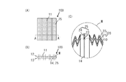
- FIG. 1 (A) shows the adhesion surface of the adsorbing member.
- FIG. 1B is a cross-sectional view taken along the line AA ′ in FIG.
- FIG. 1C is an enlarged cross-sectional view of the suction surface portion M.
- the adsorbing member 100 of the present invention is a member used to temporarily adsorb and hold the label L when adhering the label L to an adherend, and is used as an internal assembly in a label adhering device or a label adhering line.
- the adsorbing member 100 includes a base material 10 and a pad portion 20 that covers the base material surface.
- Examples of the substrate 10 include various metals and various resins.
- plate-like aluminum which is a light metal material excellent in shape stability and processability, is used.
- the substrate 10 has a plate shape composed of a substrate surface 12 and a substrate back surface 13 on which a plurality of linear recesses 11 are formed, and a large number of holes 14 penetrating the front and back are formed.
- the pad portion 20 includes a sintered body layer 21 that is formed by thermal spraying on the substrate surface 12 and a silicon-based resin layer 22 that is formed by coating the surface of the sintered body layer 21. *
- Examples of the coating material for the sintered body layer 21 include inorganic sintered bodies (ceramics), metal sintered bodies (sintering metals), and organic sintered bodies (sintered plastics). Use superior ceramics. Specifically, white alumina, gray alumina, alumina zirconia, alumina titania, chromium oxide, zirconia-yttria, etc. are preferably used.
- the base material 10 and the coating material are physically bonded by a thermal spray molding method.
- the thermal spray molding method is a technique in which a ceramic film, which is a melted (semi-molten) film material, is sprayed onto the substrate surface 12 by gas (air, carrier gas) to form a film.
- a dense sintered body layer 21 is formed on the substrate surface 12 by thermal spray molding. In the formed sintered body layer 21, a sintered hole 23 that is electrically connected to the hole 14 is formed. *
- the silicon-based resin used for the silicon-based resin layer 22 may be organic polysiloxane having general resin properties, and is preferably a blend of alkyd resin or acrylic resin in order to improve paintability.
- the sintered body layer 21 and the silicon-based resin are physically bonded by plasma coating.
- the plasma coating is a technique for forming a film by plasma ionizing a silicon-based resin as a coating material and striking it on the sintered body layer 21. Compared to a normal spray coat or the like, a film having excellent uniformity and physical strength can be formed.
- Preferred film properties are film thickness: 200 ⁇ m, surface roughness Ra 1 ⁇ m to Ra 3 ⁇ m: surface hardness: HRC45.
- Resin holes 24 communicating with the sintered holes 23 are formed in the formed silicon-based resin layer 22.
- the communicating sintered hole 23 and the resin hole 24 form a communicating hole 25.
- the holes 14 communicate with an intake or exhaust device (not shown) so as to perform an intake or exhaust action individually or collectively as a part or as a whole. *
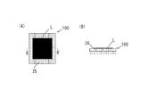
- FIG. 2A is an explanatory diagram of a state in which the label is adsorbed on the adsorption surface of the adsorption member 100.
- FIG. 1B is a cross-sectional view taken along line BB ′ in FIG.
- the adsorbing member 100 shown in FIG. 2B is provided with a first conduction hole 26 that conducts to the hole 14 communicated only with the intake device.
- the adsorbing member 100 adsorbs the label L to the pad portion 20 by the suction action by the first conduction hole 26.
- the adhesive of the label L has no fear of adhering to the suction surface because the suction surface is formed of a silicon-based resin having excellent non-stickiness.
- the suction surface has a shape reflecting the concave portion 11, the contact area with the label L is reduced, and the suction force required for label suction can be suppressed. *
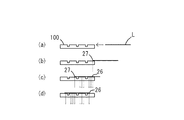
- the adsorbing member 100 shown in FIG. 3 includes a first conduction hole 26 communicated with the intake device and a second conduction hole 27 communicated with the exhaust device.
- the conduction hole 25 changes to the first conduction hole 26 or the second conduction hole 27 according to the suction operation.
- the change of the conduction hole 25 is performed by changing the device to communicate with. *
- FIG. 3A shows a process in which the peeled label L is conveyed to the adsorption member 100. At this time, the conduction hole 25 has no intake or exhaust action.
- FIG. 3B shows a state in which the label L starts to slidably contact the suction surface.
- the conduction hole 25 close to the end of the label L acts as the second conduction hole 27 so that the end of the label L does not contact the suction surface. Since the end portion of the label L where the adhesive may protrude is not in contact with the adhesive surface, the adhesive does not adhere to the adsorption surface.
- FIG. 3A shows a process in which the peeled label L is conveyed to the adsorption member 100. At this time, the conduction hole 25 has no intake or exhaust action.
- FIG. 3B shows a state in which the label L starts to slidably contact the suction surface.
- the conduction hole 25 close to the end of the label L acts as the second conduction hole 27 so that the end of the label L does
- FIG. 3C shows a state where the label L moves on the suction surface.
- the conduction hole 25 where the end of the label L is located acts as the second conduction hole 27, and the conduction hole 25 covered with the label L acts as the first conduction hole 26.
- the second conduction hole 27 also moves.
- FIG. 3D shows a state where the label L is positioned at the suction position. At this time, the conduction hole 25 covered with the label L acts as the first conduction hole 26.
- the said description assumed that the adhesive agent protruded only from the moving front-end
- the conduction hole 25 corresponding to a place where the adhesive may ooze out from the rear end or the side end of the label L can act as the second conduction hole 27.
- suction member of this invention forms the adsorption
- the suction surface has a shape reflecting the concave portion of the base material, the contact area with the label is reduced, and the suction force required for label suction and the separation force required for sticking can be suppressed.
- exhaust is performed to the conduction hole corresponding to the portion where the adhesive may ooze out, and the adhesive is prevented from coming into contact with the suction surface. That is, it is possible to consciously prevent the adhesive protruding from the label from adhering to the adsorption surface.
- Adsorbing member 10 Substrate 11 Recess 12 Substrate surface 13 Substrate surface 14 Substrate back surface 14 Hole 20 Pad part 21 Sintered body layer 22 Silicone resin layer 23 Sintered hole 24 Resin hole 25 Conductive hole 26 First conductive hole 27 Second conductive Hole L Label M Adsorption surface part
Landscapes
- Labeling Devices (AREA)
- Manipulator (AREA)
Abstract
本発明は、複数の孔(14)が形成されている基材(10)と、前記基材(10)表面に被覆し、前記孔(14)と導通する導通孔(25)を有するパッド部(20)とを備え、前記パッド部(20)を、前記基材の表面(12)に溶射形成する焼結体層(21)と、該焼結体層表面にコーティングして形成するシリコン系樹脂層(23)とから構成される吸着部材(100)により、従来のフッ素系樹脂からなるパッド部を備えた吸着部材に比して、長期間ラベルの吸着貼付動作を維持することを可能としたものである。
Description
本発明は、ラベルを吸着する吸着部材に関し、詳しくは、吸着面に接着剤が付着することを防止できる吸着部材に関する。
一般的に、ラベル貼付は、台紙からラベルを剥離すると共に、吸着部材にてラベル印字面を吸着し、被着体へ押圧することにより行われる。ここで、特定の被着体に貼付するラベルの接着面には、接着性を高めるため接着力の強い接着剤を塗布しているものがある(タイヤに貼付するラベル等)。ラベルの吸着部材への吸着は、例えば、剥離したラベルの端部を吸着面に摺接させながら行なわれる。ラベルの接着面の端部に接着剤が存在すると、接着剤が端部から印字面側に食み出てしまう。この食み出た接着剤が、上記摺接時に吸着面に付着することは避け難い。このような接着剤の付着を防止するため、吸着部材の吸着表面には、付着防止作用のある部材を用いたものがある。一般に、ラベルの接着剤の付着を防止するためには、吸着部材としてフッ素系樹脂を用いている。 このフッ素系樹脂としては、ポリテトラフルオロエチレン、テトラフルオロエチレン・ヘキサフルオロプロピレン共重合体、テトラフルオロエチレン・エチレン共重合体、テトラフルオロエチレン・パーフルオロアルキルビニルエーテル共重合体、ポリクロロトリフルオロエチレン、ポリビニリデンフルオライド等が挙げられる。 これらフッ素系樹脂は表面張力が低く非接着性に優れているため、フッ素系樹脂からなるパッドにはラベルから食み出た糊が付着し難い。
特開2008-94468号公報
しかし、フッ素系樹脂からなる吸着部材であっても、ラベルの吸着貼付動作を繰り返すと、吸着面への接着剤付着を避けることができない。特に、接着剤が吸引孔に付着してしまうと、吸引動作不良を来たしてしまい、吸着動作を止めざるおえなくなる。 本発明は、従来のフッ素系樹脂からなる吸着部材に比して、長期間ラベルの吸着貼付動作を維持することができる吸着部材を提供することを課題とする。
本発明は、印字面と接着剤が塗布された接着面とを有するラベルの印字面を吸着する吸着部材において、複数の孔が形成されている基材と、上記基材表面に被覆し、上記孔と導通する導通孔を有するパッド部とを備え、上記パッド部は、上記基材表面に溶射形成する焼結体層と、該焼結体層表面にコーティングして形成するシリコン系樹脂層とから構成する吸着部材を構成する。 ラベルを吸着するパッドの吸着面は、シリコン系樹脂にて形成されている。シリコン系樹脂は、フッ素系樹脂に比して表面張力が小さい。表面張力が小さければ粘着トルクが低くなり、非粘着性が向上する。 また、焼結体表面には多数の凹凸が形成されるため、コート時にシリコン系樹脂は凸部に埋め込まれる。故に、焼結体表面とシリコン系樹脂との接触面積が大きくなり結合性が強くなる。
上記基材表面に凹部を形成する。 パッド部表面に凹部形状が反映される。パッド部に凹部があると、ラベル吸着時にラベルとの接触面積が小さくなりラベル吸引が容易になると共に、ラベル貼付時にパッド部表面からのラベルの離反性が向上する。
上記焼結体層は、溶射により形成する。 焼結体を用いたので、表面加工が容易になる。従って、所望の表面粗さの表面が形成される。 焼結体表面の凹凸加工を容易に行うことができる。
上記シリコン系樹脂層は、プラズマコーティングにより形成する。 密度の高いコーティングが可能になる。密度を高くする程、表面張力を減少することができ、離反性が向上する。
上記導通孔は、吸気用の第1導通孔と、排気用の第2導通孔とを備える構成にする。 ラベル吸着に関与する導通孔は吸気用とし、吸着に関与しない導通孔は排気用とする。 ラベル吸着時に、第1導通孔は吸気を行い、第2導通孔は排気を行う。第2導通孔は排気を行っているので、第2導通孔内への接着剤付着が防止される。故に、第2導通孔が接着剤で塞がれることは無い。 また、吸着動作に応じて、導通孔を第1導通孔から第2導通孔に、又はその逆に変更する。接着剤が食み出たラベル端部が吸着面に接触しないように、ラベル端部が吸着面上を移動する際、ラベル端部が在る位置の導通孔を第2導通孔にする。
本発明の吸着部材は、ラベルを直接吸着する部材にシリコン系樹脂を用いるので、従来のフッ素系樹脂を用いた場合と比較して、接着剤に対する非粘着作用が強く、より長期間の貼付動作を可能にする。シリコン系樹脂が焼結体を介して基材にコーティングしているので、吸着部材からシリコン系樹脂が剥離する虞が非常に低い。また、焼結体を用いたので、膜形成を容易に行うことができる。また、プラズマコーティングにより密度の高いシリコン系樹脂のコーティングを行うので、ラベル吸着面の粘着トルクを減少させ、非粘着性を高めることができる。更に、基材表面に形成した凹部は吸着面に反映され、ラベルと吸着面との接触面積が減少する。このことは、ラベルの吸引容易性及び離反性を向上させる。また、吸気用及び排気用の作用の異なる2種類の導通孔を設けたので、ラベル吸着に関与しない第2導通孔に排気作用を持たせることができる。この第2導通孔においては、意識的に接着材の付着が防止される。
以下、本発明の実施の形態に係る吸着部材を説明する。 図1(A)は、吸着部材の接着面を示す。図1(B)は、(A)におけるA―A′線における断面図である。図1(C)は、吸着面部Mの拡大断面図である。
本発明の吸着部材100は、ラベルLを被着体に貼付する際、一旦ラベルLを吸着保持するために用いる部材であり、ラベル貼付装置やラベル貼付ラインにて内部アッセンブリとして用いられる。 吸着部材100は、基材10と基材表面に被覆するパッド部20とを備える。
基材10としては、各種金属や各種樹脂が挙げられるが、ここでは形状安定性と加工容易性に優れる材質軽金属である板状のアルミニウムを用いる。基材10は、複数の線状凹部11が形成される基材表面12と基材裏面13とからなる板形状であり、表裏を貫通する多数の孔14が形成されている。パッド部20は、基材表面12に溶射形成する焼結体層21と、焼結体層21表面にコーティングして形成するシリコン系樹脂層22とを備えて形成する。
焼結体層21の皮膜材料としては、無機焼結体(セラミックス)、金属焼結体(シンタリングメタルス)、有機焼結体(焼結プラスチックス)が挙げられるが、ここでは加工容易性に優れるセラミックスを用いる。具体的には、ホワイトアルミナ、グレーアルミナ、アルミナジルコニア、アルミナチタニア、酸化クロム、ジルコニア-イットリア等が好ましく用いられる。基材10と皮膜材料は、溶射成形法により物理的に結合している。溶射成形法は、溶かした(半溶融)状態の皮膜材料であるセラミックスを、基材表面12にガス(空気、搬送ガス)によって吹き付け皮膜を形成する技術である。溶射成形法により、基材表面12には緻密な焼結体層21が形成される。形成された焼結体層21には、孔14に導通する焼結孔23を形成する。
シリコン系樹脂層22に用いるシリコン系樹脂としては、一般的な樹脂性質を有する有機ポリシロキサンであればよく、塗装性を良好にするため、アルキド樹脂やアクリル樹脂をブレンドしたものが好ましい。 焼結体層21とシリコン系樹脂は、プラズマコーティングにより物理的に結合している。プラズマコーティングは、コート材であるシリコン系樹脂をプラズマイオン化し、焼結体層21に打ち付けることで被膜を形成する技術である。通常の吹付けコートなどに比べて、均一性に優れ、物理的強度に優れた皮膜を形成することができる。好ましい皮膜特性は、皮膜厚さ:200μm、表面粗度Ra1μm~Ra3μm:、表面硬度:HRC45である。形成されたシリコン系樹脂層22には、焼結孔23に連通する樹脂孔24を形成する。連通する焼結孔23と樹脂孔24とは、連通した導通孔25を形成する。孔14は、個々に、部分に纏まって、または全体として吸気または排気作用を奏するように図示しない吸気または排気装置に連絡する。
図2(A)は、吸着部材100の吸着面にラベルが吸着した状態の説明図である。図1(B)は、(A)のB-B′線における断面図である。図2(B)に示す吸着部材100は、吸気装置のみに連絡した孔14に導通する第1導通孔26備えたものである。吸着部材100は、ラベルLを、第1導通孔26による吸引作用でパッド部20に吸着する。吸着動作時にラベルLの接着剤は、吸着面が非粘着性に優れたシリコン系樹脂で形成している故、吸着面に付着する虞がない。 また、吸着表面は凹部11が反映された形状になるので、ラベルLとの接触面積が小さくなり、ラベル吸着に要する吸引力を抑えることができる。
図3に示す吸着部材100は、吸気装置に連絡した第1導通孔26と、排気装置に連絡した第2導通孔27とを備えたものである。導通孔25は、吸着動作に応じて第1導通孔26または第2導通孔27に変化する。この導通孔25の変化は、連絡する装置の変更により行われる。
以下、吸着動作をラベルの搬送方向断面図(時系列)で説明する。図3(a)は、剥離されたラベルLが吸着部材100に搬送される過程を示す。この時点では、導通孔25に吸気または排気作用は無い。図3(b)は、ラベルLが吸着面へ摺接し始めた状態を示す。ラベルLの端部が吸着面に接触しないように、ラベルLの端部に近い導通孔25は第2導通孔27として作用する。接着剤が食み出ている虞のあるラベルLの端部が接着面に接触しないので、接着剤が吸着面へ付着しない。図3(c)は、ラベルLが吸着面上を移動する状態を示す。ラベルLの端部が位置する導通孔25は第2導通孔27として作用し、ラベルLに覆われた導通孔25は第1導通孔26として作用する。ラベルLの移動に伴って第2導通孔27も移動する。図3(d)は、ラベルLが吸着位置に位置決めされた状態を示す。このとき、ラベルLに覆われた導通孔25は第1導通孔26として作用する。なお、上記説明は、ラベルLの移動先端のみから接着剤が食み出ていることを想定したがこれに限定されない。例えば、ラベルLの移動後端や側端から接着剤が食み出る虞がある箇所に対応した導通孔25を第2導通孔27として作用させることができる。
このように、本発明の吸着部材は、吸着面は非粘着性に優れたシリコン系樹脂で形成している故、接着剤が吸着面に付着する虞がない。 また、吸着表面は基材の凹部が反映された形状になるので、ラベルとの接触面積が少なくなり、ラベルの吸着に要する吸引力及び貼付に要する離反力を抑えることができる。 更に、吸着動作時、接着剤が食み出る虞のある箇所に対応する導通孔に排気を行なわせ、接着剤が吸着面に接触することが防止される。つまり、意識的に、ラベルから食み出た接着剤が吸着面に付着しないようにすることができる。
100 吸着部材10 基材11 凹部12 基材表面13 基材裏面14 孔20 パッド部21 焼結体層22 シリコン系樹脂層23 焼結孔24 樹脂孔25 導通孔26 第1導通孔27 第2導通孔L ラベルM 吸着面部
Claims (5)
- 印字面と接着剤が塗布された接着面とを有するラベルの印字面を吸着する吸着部材において、 複数の孔が形成されている基材と、 上記基材表面に被覆し、上記孔と導通する導通
孔を有するパッド部と、を備え、上記パッド部は、上記基材表面に溶射形成する焼結体層と、該焼結体層表面にコーティングして形成するシリコン系樹脂層とからなることを特徴とする吸着部材。 - 上記基材表面に凹部を形成したことを特徴とする請求項1記載の吸着部材。
- 上記焼結体層は、溶射により形成したことを特徴とする請求項1または2記載の吸着部材。
- 上記シリコン系樹脂層は、プラズマコーティングにより形成したことを特徴とする請求項1、2または3記載の吸着部材。
- 上記導通孔は、吸気用の第1導通孔と、排気用の第2導通孔とを備えることを特徴とする請求項1,2,3、または4記載の吸着部材。
Applications Claiming Priority (2)
| Application Number | Priority Date | Filing Date | Title |
|---|---|---|---|
| JP2011-095591 | 2011-04-22 | ||
| JP2011095591A JP5901138B2 (ja) | 2011-04-22 | 2011-04-22 | 吸着部材 |
Publications (1)
| Publication Number | Publication Date |
|---|---|
| WO2012144232A1 true WO2012144232A1 (ja) | 2012-10-26 |
Family
ID=47041361
Family Applications (1)
| Application Number | Title | Priority Date | Filing Date |
|---|---|---|---|
| PCT/JP2012/002748 Ceased WO2012144232A1 (ja) | 2011-04-22 | 2012-04-20 | 吸着部材 |
Country Status (2)
| Country | Link |
|---|---|
| JP (1) | JP5901138B2 (ja) |
| WO (1) | WO2012144232A1 (ja) |
Citations (3)
| Publication number | Priority date | Publication date | Assignee | Title |
|---|---|---|---|---|
| JPS63317439A (ja) * | 1988-05-27 | 1988-12-26 | Terumo Corp | 可撓性物品のラベル貼着用金型 |
| JP2008094468A (ja) * | 2006-10-16 | 2008-04-24 | Sato Corp | ラベル貼付装置 |
| JP2010222008A (ja) * | 2009-03-19 | 2010-10-07 | Lintec Corp | ラベル貼付装置 |
-
2011
- 2011-04-22 JP JP2011095591A patent/JP5901138B2/ja active Active
-
2012
- 2012-04-20 WO PCT/JP2012/002748 patent/WO2012144232A1/ja not_active Ceased
Patent Citations (3)
| Publication number | Priority date | Publication date | Assignee | Title |
|---|---|---|---|---|
| JPS63317439A (ja) * | 1988-05-27 | 1988-12-26 | Terumo Corp | 可撓性物品のラベル貼着用金型 |
| JP2008094468A (ja) * | 2006-10-16 | 2008-04-24 | Sato Corp | ラベル貼付装置 |
| JP2010222008A (ja) * | 2009-03-19 | 2010-10-07 | Lintec Corp | ラベル貼付装置 |
Also Published As
| Publication number | Publication date |
|---|---|
| JP5901138B2 (ja) | 2016-04-06 |
| JP2012224387A (ja) | 2012-11-15 |
Similar Documents
| Publication | Publication Date | Title |
|---|---|---|
| TW200636905A (en) | Suction device, polishing device, semiconductor device and manufacturing method of semiconductor device | |
| WO2006091519A3 (en) | Coated or bonded abrasive articles | |
| JP2005503947A5 (ja) | ||
| EP2058378A4 (en) | COATING MATERIAL FOR FORMING A BARRIER LAYER AGAINST GASES AND MULTILAYER BODY BARRIER AGAINST GASES | |
| ATE416914T1 (de) | Laminierter körper | |
| KR102488733B1 (ko) | 첩합 디바이스의 제조 장치 | |
| WO2008128948A3 (de) | Bauteil mit einem metallisierten keramikkörper | |
| EP2374612A8 (en) | Surface metal film material, process for producing surface metal film material, process for producing metal pattern material, and metal pattern material | |
| KR20130142095A (ko) | 흡착 필름과 그 제조 방법, 및 이형 필름이 부착된 흡착 필름과 그 제조 방법 | |
| JP2005205888A5 (ja) | ||
| US11548194B2 (en) | Method for manufacturing fluid device composite member | |
| JP2010135443A (ja) | 真空吸着パッドおよび真空吸着装置 | |
| EP2133922A3 (en) | Insulating coating, methods of manufacture thereof and articles comprising the same | |
| JP2018041776A (ja) | チャックテーブル及び搬送パッド | |
| WO2007019014A3 (en) | Architectural fabric | |
| JP5901138B2 (ja) | 吸着部材 | |
| JP2013226769A (ja) | 白色反射膜付基材、それを用いた白色反射膜付カバーレイシート及び白色反射膜付回路基板 | |
| WO2008045022A3 (en) | Additive particles having superhydrophobic characteristics and coatings and methods of making and using the same | |
| JP3179929U (ja) | 機能性シート部材 | |
| CN109478525A (zh) | 基板载体 | |
| ATE543209T1 (de) | Halbleitende struktur auf einem substrat mit starker rauheit | |
| CN111433388B (zh) | 基板用保护具以及附膜基板的制造方法 | |
| WO2017180502A1 (en) | Preparation of electrical circuits by adhesive transfer | |
| JP3179220U (ja) | 耐摩耗性シート部材 | |
| KR102365285B1 (ko) | 제품 기판을 코팅하기 위한 방법 및 장치 |
Legal Events
| Date | Code | Title | Description |
|---|---|---|---|
| 121 | Ep: the epo has been informed by wipo that ep was designated in this application |
Ref document number: 12774620 Country of ref document: EP Kind code of ref document: A1 |
|
| NENP | Non-entry into the national phase |
Ref country code: DE |
|
| 122 | Ep: pct application non-entry in european phase |
Ref document number: 12774620 Country of ref document: EP Kind code of ref document: A1 |