WO2012141231A1 - Batterie à l'état solide - Google Patents
Batterie à l'état solide Download PDFInfo
- Publication number
- WO2012141231A1 WO2012141231A1 PCT/JP2012/059954 JP2012059954W WO2012141231A1 WO 2012141231 A1 WO2012141231 A1 WO 2012141231A1 JP 2012059954 W JP2012059954 W JP 2012059954W WO 2012141231 A1 WO2012141231 A1 WO 2012141231A1
- Authority
- WO
- WIPO (PCT)
- Prior art keywords
- battery
- electrode layer
- negative electrode
- positive electrode
- solid
- Prior art date
Links
Images


Classifications
-
- H—ELECTRICITY
- H01—ELECTRIC ELEMENTS
- H01M—PROCESSES OR MEANS, e.g. BATTERIES, FOR THE DIRECT CONVERSION OF CHEMICAL ENERGY INTO ELECTRICAL ENERGY
- H01M10/00—Secondary cells; Manufacture thereof
- H01M10/04—Construction or manufacture in general
- H01M10/0436—Small-sized flat cells or batteries for portable equipment
-
- H—ELECTRICITY
- H01—ELECTRIC ELEMENTS
- H01M—PROCESSES OR MEANS, e.g. BATTERIES, FOR THE DIRECT CONVERSION OF CHEMICAL ENERGY INTO ELECTRICAL ENERGY
- H01M10/00—Secondary cells; Manufacture thereof
- H01M10/05—Accumulators with non-aqueous electrolyte
- H01M10/052—Li-accumulators
-
- H—ELECTRICITY
- H01—ELECTRIC ELEMENTS
- H01M—PROCESSES OR MEANS, e.g. BATTERIES, FOR THE DIRECT CONVERSION OF CHEMICAL ENERGY INTO ELECTRICAL ENERGY
- H01M10/00—Secondary cells; Manufacture thereof
- H01M10/05—Accumulators with non-aqueous electrolyte
- H01M10/056—Accumulators with non-aqueous electrolyte characterised by the materials used as electrolytes, e.g. mixed inorganic/organic electrolytes
- H01M10/0561—Accumulators with non-aqueous electrolyte characterised by the materials used as electrolytes, e.g. mixed inorganic/organic electrolytes the electrolyte being constituted of inorganic materials only
- H01M10/0562—Solid materials
-
- H—ELECTRICITY
- H01—ELECTRIC ELEMENTS
- H01M—PROCESSES OR MEANS, e.g. BATTERIES, FOR THE DIRECT CONVERSION OF CHEMICAL ENERGY INTO ELECTRICAL ENERGY
- H01M10/00—Secondary cells; Manufacture thereof
- H01M10/05—Accumulators with non-aqueous electrolyte
- H01M10/058—Construction or manufacture
- H01M10/0585—Construction or manufacture of accumulators having only flat construction elements, i.e. flat positive electrodes, flat negative electrodes and flat separators
-
- Y—GENERAL TAGGING OF NEW TECHNOLOGICAL DEVELOPMENTS; GENERAL TAGGING OF CROSS-SECTIONAL TECHNOLOGIES SPANNING OVER SEVERAL SECTIONS OF THE IPC; TECHNICAL SUBJECTS COVERED BY FORMER USPC CROSS-REFERENCE ART COLLECTIONS [XRACs] AND DIGESTS
- Y02—TECHNOLOGIES OR APPLICATIONS FOR MITIGATION OR ADAPTATION AGAINST CLIMATE CHANGE
- Y02E—REDUCTION OF GREENHOUSE GAS [GHG] EMISSIONS, RELATED TO ENERGY GENERATION, TRANSMISSION OR DISTRIBUTION
- Y02E60/00—Enabling technologies; Technologies with a potential or indirect contribution to GHG emissions mitigation
- Y02E60/10—Energy storage using batteries
-
- Y—GENERAL TAGGING OF NEW TECHNOLOGICAL DEVELOPMENTS; GENERAL TAGGING OF CROSS-SECTIONAL TECHNOLOGIES SPANNING OVER SEVERAL SECTIONS OF THE IPC; TECHNICAL SUBJECTS COVERED BY FORMER USPC CROSS-REFERENCE ART COLLECTIONS [XRACs] AND DIGESTS
- Y02—TECHNOLOGIES OR APPLICATIONS FOR MITIGATION OR ADAPTATION AGAINST CLIMATE CHANGE
- Y02P—CLIMATE CHANGE MITIGATION TECHNOLOGIES IN THE PRODUCTION OR PROCESSING OF GOODS
- Y02P70/00—Climate change mitigation technologies in the production process for final industrial or consumer products
- Y02P70/50—Manufacturing or production processes characterised by the final manufactured product
Definitions
- the present invention generally relates to a solid state battery, and more particularly to a solid state battery having a stacked positive electrode layer, solid electrolyte layer, and negative electrode layer.
- Lithium ion secondary batteries using non-aqueous electrolyte are used for power supplies for small electronic devices and auxiliary power supplies for memory backup.
- the lithium ion secondary battery having the above configuration there is a risk that the electrolyte solution leaks.
- the lithium ion secondary battery having the above configuration is used as an auxiliary power source for memory backup, etc., when the surrounding electronic circuit is wetted by the leaked electrolyte, problems such as malfunction or malfunction of the electronic circuit occur. there is a possibility.
- the lithium ion secondary battery and the electronic circuit have been conventionally mounted in different places.
- Patent Document 1 Japanese Patent Laid-Open No. 2010-118159 proposes a configuration of a battery that can be mounted on a substrate together with electronic circuit components.
- a battery laminate having a positive electrode layer, a negative electrode layer, and a solid electrolyte layer disposed between these layers is housed in a sealed case (exterior body) that can be mounted on a substrate.
- a stack connection electrode portion is provided in a current collector formed so as to be connected to each electrode layer of the battery stack.
- the sealed case is provided with a case connection electrode portion including an external terminal portion corresponding to each electrode layer. Furthermore, the laminated body connection electrode part and the case connection electrode part are connected by wire bonding of lead wires in the sealed case.
- a conductive paste or the like may be used as a material for the laminated body connection electrode portion.
- the solid electrolyte constituting each electrode layer of the battery laminate and the conductive paste forming the laminate connection electrode portion are in direct contact and react. There is. For this reason, the performance of a battery may deteriorate.
- an object of the present invention is to provide a configuration of a solid state battery that can maintain good electrical connection with the electrode layer of the battery body and can suppress deterioration in battery performance.
- the solid battery according to the present invention includes a battery body, a housing member, a positive terminal and a negative terminal, and a current collecting member.
- the battery body includes a positive electrode layer, a solid electrolyte layer, and a negative electrode layer.
- the housing member houses the battery body.
- the positive electrode terminal and the negative electrode terminal are disposed on the outer surface of the housing member.
- the housing member includes a conductor portion connected to the positive terminal and the negative terminal.
- the current collecting member is disposed between at least one of the positive electrode layer or the negative electrode layer and the housing member so as to be connected to the conductor portion of the housing member, has elasticity, and includes a conductive substance.
- the current collecting member having elasticity is disposed between at least one of the positive electrode layer or the negative electrode layer and the housing member. For this reason, in a state where an urging force that opposes the elasticity of the current collecting member is applied to the battery body, at least one of the positive electrode layer or the negative electrode layer of the battery body is connected to the conductor portion of the housing member.
- the battery body is disposed in the housing member. Therefore, since the battery body does not easily move in the housing member, the electrical connection between the electrode layer of the battery body and the conductor portion of the housing member can be kept good.
- an electrode of the battery element body can be obtained simply by interposing an elastic current collecting member between at least one of the positive electrode layer or the negative electrode layer and the housing member. Electrical connection between the layer and the conductor portion of the housing member can be made. For this reason, while being able to simplify a manufacturing process, an accommodating member can be made small. Therefore, it is possible to easily reduce the size of the mounting type solid battery.
- the current collecting member contains at least one of a carbon material and a conductive rubber.
- the current collecting member includes at least one of a carbon sheet and an anisotropic conductive rubber sheet.
- the carbon material or the conductive rubber does not react with the sulfide-based solid electrolyte or the like. , Deterioration of battery performance can be suppressed.
- the housing member is bonded to the insulating base so as to cover the insulating base having a surface on which the battery base is placed and the battery base placed on the surface of the insulating base. It is preferable that the cover member is included. Furthermore, it is preferable that at least one of the insulating base material and the lid member has a recess that accommodates at least a part of the battery body.
- the housing member when the housing member includes an insulating base material having a surface on which the battery body is placed, the insulating base material has an electrode for electrically connecting the inner side surface and the outer side surface of the insulating base material. It is preferable that the connection part is formed, and the electrode connection part includes a positive electrode connection part connected to the positive electrode layer and a negative electrode connection part connected to the negative electrode layer.
- the current collecting member has a peripheral side wall portion formed so as to surround at least a part of the outer surface of the battery body.
- the peripheral side wall portion of the current collecting member serves as a stopper for the movement of the battery element body, it is possible to prevent the displacement of the battery element body in the housing member.
- the housing member covers the insulating base material having the surface on which the battery body is placed and the battery base material placed on the surface of the insulating base material.
- the positive electrode layer and the negative electrode layer may be laminated in a direction in which the insulating substrate and the cover member face each other, or the positive electrode layer and the negative electrode layer are
- the insulating base material may be laminated in the extending direction.
- the positive electrode layer and the negative electrode layer are laminated in the direction in which the insulating base material extends, when the insulating base material is placed on the surface of the substrate, the positive electrode layer and the negative electrode layer are arranged in the direction in which the surface of the substrate extends. Can be arranged. Thereby, each surface of a positive electrode layer and a negative electrode layer can be made to oppose the surface of a board
- the solid state battery of the present invention further includes an insulating member disposed between the lid member and the battery body.
- a solid state battery includes a battery body, a housing member, a positive terminal and a negative terminal, and a current collecting member.
- the battery body includes a positive electrode layer, a solid electrolyte layer, and a negative electrode layer.
- the housing member houses the battery body.
- the positive electrode terminal and the negative electrode terminal are arranged so as to be drawn out from the inside of the housing member.
- the current collecting member is disposed between at least one of the positive electrode layer or the negative electrode layer and the housing member so as to be connected to at least one of the positive electrode terminal or the negative electrode terminal, and has an elastic and conductive material.
- a solid state battery includes a battery body, a housing member, a positive electrode terminal and a negative electrode terminal, and a current collecting member.
- the battery body includes a positive electrode layer, a solid electrolyte layer, and a negative electrode layer.
- the housing member houses the battery body.
- the current collecting member is disposed between the battery body and the housing member, has elasticity, and includes a conductive substance.
- the electrical connection between the electrode layer of the battery body and the conductor portion of the housing member can be maintained well. Moreover, when a current collection member contains a carbon material or conductive rubber, deterioration of battery performance can be suppressed.
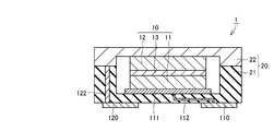
- a planar mounting type solid battery 1 includes a battery body 10 and a housing member 20 that houses the battery body 10.
- an all solid state secondary battery includes a solid electrolyte layer 13 sandwiched between a positive electrode layer 11 and a negative electrode layer 12.
- the positive electrode layer 11 includes, for example, a Li 2 FeS 2, LiFePO 4 or LiCoO 2 as a positive electrode active material, Li 2 S-P 2 S 5 based composition as a solid electrolyte or a Li 3 PS 4.
- the negative electrode layer 12 includes, for example, graphite as a negative electrode active material and Li 2 SP—S 2 S 5 composition or Li 3 PS 4 as a solid electrolyte.
- the solid electrolyte layer 13 sandwiched between the positive electrode layer 11 and the negative electrode layer 12 is a Li 2 SP—S 2 S 5 composition or Li 3 PS 4 .
- the housing member 20 includes an insulating base material 21 and a metal lid member 22.
- the insulating base material 21 has a surface on which the battery body 10 is placed.
- the metal lid member 22 is joined to the insulating base material 21 so as to cover the battery body 10 placed on the surface of the insulating base material 21.
- Each of the insulating base material 21 and the metal lid member 22 has a recess for accommodating a part of the battery body 10.
- the battery body 10 is mounted on the bottom surface of the recess of the insulating base material 21 with the current collecting member 111 interposed.
- the current collecting member 111 is made of a material having elasticity and containing a conductive substance.
- the current collecting member 111 is preferably formed of a carbon material or a material containing a conductive rubber, and is a carbon sheet or an anisotropic conductive rubber sheet. More preferably it consists of:
- the metal lid member 22 is joined to the insulating base material 21 via a metallized layer (not shown) so as to cover the battery body 10 mounted on the surface of the insulating base material 21.
- the metallized layer is formed, for example, by printing and baking a metal paste whose main component is a metal such as tungsten (W).
- Insulating base material 21 is formed from ceramics, such as alumina, for example.
- the metal lid member 22 is made of a metal such as aluminum (Al) or copper (Cu), or an alloy such as iron (Fe) -nickel (Ni) -cobalt (Co) alloy.
- the battery body 10 is disposed inside the housing member 20 so that the outer surface of the negative electrode layer 12 is in contact with the inner surface of the metal lid member 22.
- the insulating base material 21 is formed of ceramics.
- the insulating base material 21 may be formed of an insulating material such as a synthetic resin that can withstand the heating temperature in the reflow furnace. .
- a positive electrode connection part 112 and a negative electrode connection part 122 are arranged as electrode connection parts that electrically connect the inner side surface and the outer side surface of the insulating base material 21. Formation of the positive electrode connection part 112 and the negative electrode connection part 122 is performed as follows. First, a ceramic paste constituting the insulating substrate 21 is printed with a metal paste mainly composed of a metal such as tungsten (W) on the surface of the green sheet, or formed on the green sheet. A printed pattern to be a conductive layer of the positive electrode connection portion 112 and the negative electrode connection portion 122 is formed by printing and filling the holes. Next, the green sheets on which these printed patterns are formed are stacked and baked to produce the insulating base material 21 having the positive electrode connection portion 112 and the negative electrode connection portion 122 inside.
- a ceramic paste constituting the insulating substrate 21 is printed with a metal paste mainly composed of a metal such as tungsten (W) on the surface of the green sheet, or formed on the green sheet.
- the positive electrode terminal 110 and the negative electrode terminal 120 are arranged on the lower surface as the outer surface on one side of the insulating base material 21.
- the positive electrode layer 11 of the battery body 10 is connected to the positive electrode terminal 110 through the current collecting member 111 and the positive electrode connecting portion 112.
- the negative electrode layer 12 of the battery body 10 is connected to the negative electrode terminal 120 through the metal lid member 22 and the negative electrode connection part 122. Formation of the positive electrode terminal 110 and the negative electrode terminal 120 is performed as follows. First, a metal paste mainly composed of a metal such as tungsten (W) is printed on a ceramic green sheet constituting the insulating base material 21 to form a print pattern to be a conductor layer of the positive electrode terminal 110 and the negative electrode terminal 120. To do.
- the insulating base material 21 which has the positive electrode terminal 110 and the negative electrode terminal 120 on the outer surface is produced by baking the green sheet in which these printing patterns were formed.
- the positive electrode terminal 110 and the negative electrode terminal 120 are formed in the same process as the formation of the positive electrode connection portion 112 and the negative electrode connection portion 122 described above.
- a nickel (Ni) layer and a gold (Au) layer are formed on the surfaces of the positive electrode terminal 110 and the negative electrode terminal 120 by a plating method or the like.
- Insulating substrate 21 having positive electrode terminal 110 and negative electrode terminal 120 on the outer surface may be produced by firing a ceramic green sheet constituting insulating substrate 21 and then forming a conductor layer.
- the method for producing the insulating base material 21 is not particularly limited.
- the insulating base material 21 constituting the housing member 20 includes a positive electrode connection portion 112 as a conductor portion connected to the positive electrode terminal 110 and a negative electrode connection portion 122 as a conductor portion connected to the negative electrode terminal 120.
- the current collecting member 111 is disposed between the positive electrode layer 11 and the insulating base material 21 so as to be connected to the positive electrode connecting part 112 as a conductor part of the insulating base material 21.
- the current collecting member 111 may be disposed not between the positive electrode layer 11 and the insulating base material 21 but between the negative electrode layer 12 and the metal lid member 22.
- the current collecting member 111 having elasticity is disposed between the positive electrode layer 11 or the negative electrode layer 12 and the housing member 20. Yes. Therefore, at least one of the positive electrode layer 11 and the negative electrode layer 12 of the battery body 10 acts as a conductor portion of the housing member 20 in a state where the biasing force that opposes the elasticity of the current collector 111 acts on the battery body 10.
- the battery body 10 is disposed in the housing member 20 so as to be connected. Therefore, since the battery body 10 does not easily move in the housing member 20, the electrical connection between the electrode layer of the battery body 10 and the conductor portion of the housing member 20 can be kept good.
- the solid state battery 1 of the present invention there is no need for wire bonding, and only by having a current collecting member 111 having elasticity between at least one of the positive electrode layer 11 or the negative electrode layer 12 and the housing member 20, Electrical connection between the electrode layer of the battery body 10 and the conductor portion of the housing member 20 can be performed. For this reason, while being able to simplify a manufacturing process, the accommodating member 20 can be made small. Therefore, the mounting type solid battery 1 can be easily downsized.
- the current collecting member 111 when the current collecting member 111 includes a carbon material or conductive rubber, the current collecting member having elasticity between at least one of the positive electrode layer 11 and the negative electrode layer 12 and the housing member 20. Even if the member 111 is interposed, since the carbon material or the conductive rubber does not react with the electrode material or the like, it is possible to suppress the deterioration of the battery performance.
- the solid battery 1 of the present invention can withstand the heating temperature in the reflow furnace because the housing member 20 houses the battery body 10 containing the solid electrolyte instead of the liquid electrolyte. Thereby, the solid battery 1 of the present invention can be surface-mounted on a substrate by reflow soldering.
- the positive electrode connection portion 112 and the negative electrode connection portion 122 are disposed inside the insulating base material 21, and the positive electrode terminal 110 and the negative electrode terminal 120 are disposed on the lower surface of the insulating base material 21.
- the positive electrode layer 11 and the negative electrode layer 12 of the battery body 10 are connected to the positive electrode terminal 110 and the negative electrode terminal 120 through the positive electrode connection portion 112 and the negative electrode connection portion 122, respectively.
- the positive electrode terminal 110 and the negative electrode terminal 120 are arranged on the lower surface, which is the outer surface on one side of the insulating base material 21, the wiring board connected to the positive electrode terminal 110 and the negative electrode terminal 120.
- a reflow soldering process can be performed by supplying a paste-like solder material to the upper portion in advance.
- a metallized layer is formed on the insulating base material 21 to be joined to the metal lid member 22, and the insulating base material 21 and the metal lid member 22 are joined via the metallized layer.
- the metal lid member 22 is electrically connected to the negative electrode connection portion 122 by connecting the negative electrode connection portion 122 disposed inside and the metallized layer, and the metal lid member is connected to the negative electrode layer 12 of the battery body 10. 22 is electrically connected through the negative electrode connecting portion 122, so that the metal lid member 22 is configured as a conductive path.
- a predetermined voltage is applied to the outer surface of the metal cover member 22 using a seam welding method, and the metal cover member 22 and the insulating base material 21 are efficiently joined by welding.
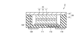
- the insulating base 21 has a recess for housing the battery body 10, and the metal lid member 22 is flat. It is.
- the other structure of the solid battery 2 is the same as that of the solid battery 1 shown in FIG.
- the solid battery 2 can also achieve the same effects as the solid battery 1 described above.
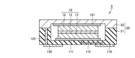
- the current collecting member 111 is disposed between the positive electrode layer 11 and the insulating base material 21, and The member 121 is disposed between the negative electrode layer 12 and the metal lid member 22.
- the other structure of the solid battery 3 is the same as that of the solid battery 1 shown in FIG.
- the solid battery 3 can also achieve the same effects as the solid battery 1 described above.
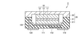
- FIG. 4 As shown in FIG. 4, as a fourth embodiment of the present invention, in the flat-mount type solid battery 4, a step is formed on the inner side wall forming the concave portion of the insulating base material 21, thereby being positioned further inside.
- a peripheral side wall portion 211 is provided in the concave portion of the insulating base material 21.
- the peripheral side wall portion 211 is formed so as to surround an outer peripheral side surface that is a part of the outer surface of the current collecting member 111.
- the other structure of the solid battery 4 is the same as that of the solid battery 1 shown in FIG.
- the peripheral side wall portion 211 of the concave portion of the insulating base material 21 serves as a stopper against the movement of the current collecting member 111, so that the position shift of the current collecting member 111 within the housing member 20 is prevented. Further, it can be effectively prevented.
- the solid battery 4 can also achieve the same effects as the solid battery 1 described above.
- the peripheral side wall portion positioned further inside is formed on the metal lid member 22.
- the peripheral side wall provided in the recess of the metal lid member 22 is formed so as to surround the outer peripheral side surface that is a part of the outer surface of the current collecting member 121. In this way, it is possible to prevent the displacement of the current collecting member 121 in the housing member 20 more effectively.
- a step is formed on the inner side wall forming the concave portion of the metal lid member 22, thereby being positioned further inside.
- a peripheral side wall portion 221 is provided in the concave portion of the metal lid member 22.
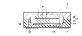
- the peripheral side wall portion 221 is formed so as to surround an outer peripheral side surface that is a part of the outer surface of the battery body 10.
- the other structure of the solid battery 5 is the same as that of the solid battery 4 shown in FIG. With such a configuration, the peripheral side wall portion 221 of the concave portion of the metal lid member 22 serves as a stopper against the movement of the battery body 10, so that the battery body within the housing member 20 is more effectively produced. 10 position shifts can be prevented.
- the solid battery 5 can also achieve the same effects as the solid battery 4 described above.
- FIG. 6 As shown in FIG. 6, as the sixth embodiment of the present invention, in the planar mounting type solid battery 6, a recess is formed in the current collecting member 111 so as to accommodate a bottom part that is a part of the battery body 10.
- the peripheral side wall portion 1111 is provided on the current collecting member 111.
- the peripheral side wall portion 1111 is formed so as to surround an outer peripheral side surface that is a part of the outer surface of the battery body 10.
- the other structure of the solid battery 6 is the same as that of the solid battery 4 shown in FIG. With such a configuration, the peripheral side wall portion 1111 of the concave portion of the current collecting member 111 serves as a stopper against the movement of the battery body 10, so that the battery body in the housing member 20 can be more effectively produced. 10 position shifts can be prevented.
- the solid battery 6 can also achieve the same effects as the solid battery 4 described above.
- the positive electrode layer 11 and the negative electrode layer 12 are laminated in a direction in which the insulating base material 21 and the metal lid member 22 face each other.
- a planar mounting type solid battery 7 includes a battery body 10 and a housing member 30 that houses the battery body 10.
- the housing member 30 includes an insulating base material 31 and an insulating lid member 32.
- the insulating base material 31 has a surface on which the battery body 10 is placed.
- the insulating lid member 32 is bonded to the insulating base material 31 so as to cover the battery body 10 placed on the surface of the insulating base material 31.
- the insulating base 31 has a recess that accommodates a part of the battery body 10, and the insulating lid member 32 has a flat plate shape.
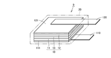
- the battery body 10 is formed by sequentially laminating the positive electrode layer 11, the solid electrolyte layer 13, and the negative electrode layer 12 in the direction in which the insulating base material 31 extends.
- the peripheral side wall part 311 is provided in the recessed part of the insulating base material 31 by forming a level
- the peripheral side wall portion 311 is formed so as to surround the outer peripheral side surface that is a part of the outer surface of each of the current collecting members 111 and 112.
- the inner peripheral side wall 312 of the insulating base 31 is formed so as to surround a part of the outer surface of the battery body 10.
- the battery body 10 is mounted on the inner bottom surface of a recess serving as the surface of the insulating base material 31 with current collecting members 111 and 121 interposed therebetween.
- a positive electrode connection portion 112 and a negative electrode connection portion 122 are formed on the insulating base material 31 as electrode connection portions for conducting the inner surface and the outer surface of the insulating base material 31.
- the battery body 10 is a concave portion of the insulating base material 31 such that the positive electrode connecting portion 112 is connected to the positive electrode layer 11 through the current collecting member 111 and the negative electrode connecting portion 122 is connected to the negative electrode layer 12 through the current collecting member 121. It is arranged on the bottom.
- the positive electrode layer 11 is connected to the positive electrode terminal 110 through the current collecting member 111 and the positive electrode connecting portion 112.
- the negative electrode layer 12 is connected to the negative electrode terminal 120 through the current collecting member 121 and the negative electrode connecting portion 122.
- the insulating base 31 and the insulating lid member 32 are joined together by an adhesive layer 40 made of, for example, an epoxy resin.
- the insulating base 31 and the insulating lid member 32 are made of ceramics such as alumina, for example.
- the other configuration of the solid battery 7 is the same as that of the solid battery 1 shown in FIG.
- the positive electrode layer 11 and the negative electrode layer 12 are laminated in the direction in which the insulating base material 31 extends, when the insulating base material 31 is placed on the surface of the substrate, the positive electrode layer 11 and the negative electrode layer 12 can be arranged side by side in the direction in which the surface of the substrate extends. Thereby, each surface of the positive electrode layer 11 and the negative electrode layer 12 can be made to oppose the surface of a board
- the insulating lid member 32 is shown smaller than the insulating base material 31, but the insulating base material 31 and the insulating lid member 32 may be the same size as long as the housing member 30 is sealed.
- the insulating lid member 32 may be larger than the insulating base material 31.
- the two peripheral side wall portions 311 of the concave portion of the insulating base material 31 serve as a stopper for the movement of the current collecting members 111 and 121, the displacement of the current collecting members 111 and 121 in the housing member 20 is prevented. Can be prevented.
- the inner peripheral side wall portion 312 of the insulating base material 31 serves as a stopper for the movement of the battery body 10, it is possible to prevent the positional deviation of the battery body 10 within the housing member 20.
- the solid battery 7 can also achieve the same effects as the solid battery 1 described above.
- each of the insulating base material 31 and the insulating lid member 32 is a recess that accommodates a part of the battery body 10.
- the insulating base 31 and the insulating lid member 32 are joined by an epoxy resin or the like.
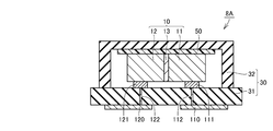
- An insulating interposition member 50 is disposed so as to contact the surface opposite to the surface of the battery body 10 on the side facing the insulating base 31. That is, the insulating interposed member 50 is disposed between the battery body 10 and the insulating lid member 32. More specifically, the insulating interposition member 50 is disposed between the inner bottom surface of the recess of the insulating lid member 32 and the battery body 10.
- the other structure of the solid battery 8 is the same as that of the solid battery 7 shown in FIG.
- the insulating interposed member 50 presses the battery body 10 toward the insulating base 31. Act on. For this reason, it is possible to prevent the displacement of the battery body 10 in the housing member 30. Further, when the lid member is made of metal, an electrical short circuit can be prevented.
- the solid battery 8 can also achieve the same effects as the solid battery 7 described above.
- the insulating lid member 32 has a recess that accommodates a part of the battery body 10.
- the insulating substrate 31 has a flat plate shape.
- a cavity for filling the insulating base material 31 with a conductive material is formed, and by filling the cavity with the conductive material, an electrode connection portion for connecting the inner side surface and the outer side surface of the insulating base material 31 is provided.
- a positive electrode connection portion 112 and a negative electrode connection portion 122 are formed.
- the other configuration of the solid battery 8A is the same as that of the solid battery 8 shown in FIG.
- the insulating interposed member 50 presses the battery body 10 toward the insulating base 31. Act on. For this reason, it is possible to prevent the displacement of the battery body 10 in the housing member 30. Further, when the lid member is made of metal, an electrical short circuit can be prevented.
- the insulating interposition member 50 is not necessarily arranged, and the current collecting members 111 and 121 having elasticity are arranged between the positive electrode layer 11 and the negative electrode layer 12 and the insulating base material 31. For this reason, the positive electrode layer 11 and the negative electrode layer 12 of the battery body 10 are connected to the conductor portion of the insulating base material 31 in a state where the biasing force that opposes the elasticity of the current collecting members 111 and 121 acts on the battery body 10. Thus, the battery body 10 is disposed in the housing member 30. Therefore, since the battery body 10 does not easily move in the housing member 30, the electrical connection between the electrode layer of the battery body 10 and the conductor portion of the insulating base 31 can be kept good.
- the solid battery 9 includes a battery body 10 and a housing member 20 that houses the battery body 10.
- the battery body 10 includes a solid electrolyte layer 13 sandwiched between a positive electrode layer 11 and a negative electrode layer 12.
- the housing member 20 is made of an aluminum laminate film.
- the positive electrode terminal 110 and the negative electrode terminal 120 are arranged so as to be drawn out from the inside of the housing member 20.
- the current collecting member 111 is disposed between the positive electrode layer 11 and the housing member 20 so as to be connected to the positive electrode terminal 110.
- the current collecting member 121 is disposed between the negative electrode layer 12 and the housing member 20 so as to be connected to the negative electrode terminal 120.
- At least one of the insulating base material or the lid member has a concave portion that accommodates at least a part of the battery element body
- at least one concave portion of the insulating base material or the lid member is It is preferable to have a peripheral side wall portion formed so as to surround at least a part of the outer surface of the battery body.
- the peripheral side wall portion of the recess serves as a stopper for the movement of the battery body, it is possible to prevent the displacement of the battery body in the housing member.
- the current collecting member has an outer surface, and the peripheral side wall is formed so that at least one of the recesses of the insulating base material or the lid member surrounds at least a part of the outer surface of the current collecting member It is preferable to have a part. In this case, since the peripheral side wall part of the said recessed part plays the role of a stopper with respect to the movement of a current collection member, position shift of the current collection member within an accommodating member can be prevented.
- the housing member may have a form of a metal can or resin sealing.
- Li 2 FeS 2 or LiCoO 2 as a positive electrode active material Li 2 S-P 2 S 5 based composition or Li 3 PS 4 as a solid electrolyte
- the following materials may be used.
- the positive electrode active material examples include a lithium-containing phosphate compound having a NASICON structure such as Li 3 V 2 (PO 4 ) 3 , a lithium-containing phosphate compound having an olivine structure such as LiFePO 4 and LiMnPO 4 , LiCoO 2 , and LiCo.
- a layered compound such as 1/3 Ni 1/3 Mn 1/3 O 2 or a lithium-containing compound having a spinel structure such as LiMn 2 O 4 or LiNi 0.5 Mn 1.5 O 4 can be used.
- MOx (M includes at least one element selected from the group consisting of Ti, Si, Sn, Cr, Fe and Mo, and x is in the range of 0.9 ⁇ x ⁇ 2.0.
- a compound having a composition represented by the following numerical value can be used.
- TiO 2 and SiO 2 2 more than one active material having a composition represented by MOx containing different element M may be a mixture obtained by mixing the like.
- graphite-lithium compounds, lithium alloys such as Li-Al, oxidation of Li 3 V 2 (PO 4 ) 3 , Li 3 Fe 2 (PO 4 ) 3 , Li 4 Ti 5 O 12, etc. Thing, etc. can be used.
- a lithium-containing phosphate compound having a NASICON structure can be used as the solid electrolyte.
- Lithium-containing phosphoric acid compound having a NASICON-type structure the chemical formula Li x M y (PO 4) 3 ( Formula, x 1 ⁇ x ⁇ 2, y is a number in the range of 1 ⁇ y ⁇ 2, M Represents one or more elements selected from the group consisting of Ti, Ge, Al, Ga and Zr). In this case, a part of P in the above chemical formula may be substituted with B, Si or the like.
- lithium-containing phosphate compounds having a NASICON type structure such as Li 1.5 Al 0.5 Ge 1.5 (PO 4 ) 3 and Li 1.2 Al 0.2 Ti 1.8 (PO 4 ) 3 are mixed. You may use the mixture.
- the lithium-containing phosphate compound having a NASICON structure used in the above solid electrolyte includes a crystal phase of a lithium-containing phosphate compound having a NASICON structure, or a lithium-containing phosphate having a NASICON structure by heat treatment You may use the glass which precipitates the crystal phase of a phosphoric acid compound.
- a material used for said solid electrolyte it is possible to use the material which has ion conductivity and is so small that electronic conductivity can be disregarded other than the lithium-containing phosphate compound which has a NASICON structure.
- examples of such a material include lithium halide, lithium nitride, lithium oxyacid salt, and derivatives thereof.
- Li-PO system compounds such as lithium phosphate (Li 3 PO 4 ), LIPON (LiPO 4 ⁇ x N x ) in which nitrogen is mixed with lithium phosphate, and Li—Si—O such as Li 4 SiO 4
- Li—Si—O such as Li 4 SiO 4
- Compounds such as La-based compounds, Li-P-Si-O based compounds, Li-V-Si-O based compounds, La 0.51 Li 0.35 TiO 2.94 , La 0.55 Li 0.35 TiO 3 , Li 3x La 2 / 3-x TiO 3, etc. Examples thereof include compounds having a lobskite structure, compounds having a garnet structure having Li, La, and Zr.
- the current collecting member preferably has a Young's modulus of 10 GPa or less and a conductivity of 1 ⁇ 10 ⁇ 3 S or more.
- the electrical conductivity of the current collecting member is lower than 1 ⁇ 10 ⁇ 3 S, the electrical connection is deteriorated.
- the Young's modulus of the current collecting member is larger than 10 GPa, an appropriate pressure is not applied to the battery body 10, and the battery body 10 may be displaced within the housing member 20 due to vibration or the like.
- the material of a current collection member is a material which does not react with battery constituent materials, such as a solid electrolyte or an electrode active material.
- the current collecting member for example, natural rubber, isoprene rubber, butadiene rubber, diene special rubber, olefin rubber, ether rubber, polysulfide rubber, urethane rubber, fluorine rubber, silicone rubber, etc.
- Rubber including elastomer
- phenol resin phenol-formaldehyde resin, bakelite, carboxylic acid resin
- urea resin melamine resin
- epoxy resin unsaturated polyester resin, alkyd resin, silicone resin, urethane resin, furan resin, unsaturated Thermosetting resins
- polyester polyolefins (polyethylene, polypropylene, etc.), polyvinyl chloride, polyvinylidene chloride, polyvinyl alcohol, polystyrene, polyvinyl acetate, fluorine resins (polytetrafluoroethylene (Teflon; DuPont) Registered trademark), polyacetal, polyester resin (polyethylene terephthalate, etc.), acrylic resin (polyacrylonitrile, etc.), methacryl resin, acrylonitrile butadiene styrene resin (ABS resin), thermoplastic resin such as phenoxy resin; polyamide, polyacetal, polycarbonate
- General-purpose engineering plastics such
- the above polymer materials may be used alone or in combination of two or more.
- metal oxides such as indium tin oxide (ITO), indium oxide, tin oxide, SiO 2 and TiO 2 , noble metals such as gold and silver, and metal particles such as Cu can be used.
- ITO indium tin oxide
- tin oxide SiO 2 and TiO 2
- noble metals such as gold and silver
- metal particles such as Cu
- Example 1 A battery body 10 shown in FIG. 1 was prepared using Li 2 FeS 2 as a positive electrode active material, graphite as a negative electrode active material, and Li 3 PS 4 as a solid electrolyte.
- a positive electrode material was produced by mixing Li 2 FeS 2 and Li 3 PS 4 at a mass ratio of 1: 1.
- a negative electrode material was produced by mixing graphite and Li 3 PS 4 at a mass ratio of 1: 1.
- a positive electrode material, a solid electrolyte, and a negative electrode material obtained as described above were sequentially laminated, and a three-layered pellet was press-molded at a pressure of 3000 kgf / cm 2 .
- a battery body 10 including a solid electrolyte layer 13 sandwiched between the positive electrode layer 11 and the negative electrode layer 12 was obtained.
- a metal paste mainly composed of tungsten (W) metal powder is printed and applied to an alumina compact as a conductor and terminals. A printed pattern was formed.
- the positive electrode connecting portion 112 and the negative electrode connecting portion 122 are provided as conductor portions inside, and the positive electrode terminal 110 and the negative electrode terminal 120 are provided on the outer surface.
- the insulating base material 21 having was produced.
- a metallized layer was formed on the top surface of the recess of the insulating base material 21.
- a nickel (Ni) layer and a gold (Au) layer were formed on the surfaces of the positive electrode terminal 110 and the negative electrode terminal 120 by a plating method.
- the positive electrode layer 11 side of the battery base body 10 is on the bottom and on the bottom surface of the recess of the insulating base material 21 as shown in FIG. Then, the battery body 10 was placed with a carbon sheet interposed as the current collecting member 111. Thus, the battery body 10 was placed on the bottom surface of the concave portion of the insulating base 21 so as to be electrically connected between the positive electrode connecting portion 112 and the positive electrode layer 11 through the current collecting member 111.
- a metallized layer is interposed on the top surface of the concave portion of the insulating base material 21 so as to cover the battery body 10 mounted on the bottom surface of the concave portion of the insulating base material 21 and is made of an iron-nickel-cobalt alloy.
- a metal lid member 22 was disposed. Furthermore, the metal lid member 22 and the insulating base material 21 were joined by welding by applying a predetermined voltage to the outer surface of the metal lid member 22 using a seam welding method. In this way, a surface mount type solid battery 1 was produced.
- Example 2 As the solid electrolyte powder, glass powder having a composition of Li 1.5 Al 0.5 Ge 1.5 (PO 4 ) 3 was used. As the electrode active material powder, a powder having a crystal phase of Li 3 V 2 (PO 4 ) 3 was used.
- the solid electrolyte powder as a main material, polyvinyl butyral resin, and alcohol were weighed to a weight ratio of 100: 15: 140.
- Polyvinyl butyral resin was dissolved in alcohol to prepare a solid electrolyte slurry.
- a mixed powder obtained by mixing 50 parts by weight of a solid electrolyte powder, 45 parts by weight of an electrode active material powder, and 5 parts by weight of carbon powder as a conductive agent in a mortar is used as a main material, and the main material, polyvinyl butyral resin, and alcohol are used.
- An electrode slurry was prepared in the same manner as the solid electrolyte slurry by weighing to a weight ratio of 100: 15: 140.
- a solid electrolyte slurry was coated on a polyethylene terephthalate (PET) film, dried on a hot plate heated to a temperature of 40 ° C., and a solid electrolyte green sheet was prepared to a thickness of 50 ⁇ m. .
- PET polyethylene terephthalate
- the electrode slurry was coated on a polyethylene terephthalate (PET) film using a doctor blade method and dried on a hot plate heated to a temperature of 40 ° C. to prepare an electrode green sheet having a thickness of 50 ⁇ m.
- PET polyethylene terephthalate
- the obtained green sheet laminate was cut into a size of 10 mm ⁇ 10 mm to produce a laminate.
- the obtained laminate was fired at a temperature of 500 ° C. in an air atmosphere to remove the polyvinyl butyral resin, and then sintered at a temperature of 700 ° C. in a nitrogen gas atmosphere to prepare a sintered body. .
- a platinum (Pt) layer is formed as a current collector layer by sputtering on the outer surface of each of the positive electrode layer and the negative electrode layer of the obtained sintered body.
- Pt platinum
- a planar mounting type solid battery 1 shown in FIG. 1 was produced in the same manner as in Example 1.
- Example 3 A battery body 10 shown in FIG. 1 was prepared using Li 2 FeS 2 as a positive electrode active material, graphite as a negative electrode active material, and Li 3 PS 4 as a solid electrolyte.
- a positive electrode material was produced by mixing Li 2 FeS 2 and Li 3 PS 4 at a mass ratio of 1: 1.
- a negative electrode material was produced by mixing graphite and Li 3 PS 4 at a mass ratio of 1: 1.
- a positive electrode material, a solid electrolyte, and a negative electrode material obtained as described above were sequentially laminated, and a three-layered pellet was press-molded at a pressure of 3000 kgf / cm 2 .
- a battery body 10 including a solid electrolyte layer 13 sandwiched between the positive electrode layer 11 and the negative electrode layer 12 was obtained.
- Example 4 The solid battery 1 shown in FIG. 1 was produced in the same manner as in Example 1. However, an anisotropic conductive sheet (MT type manufactured by Shin-Etsu Chemical) was used as the current collecting member 111.
- MT type manufactured by Shin-Etsu Chemical
- a battery body 10 was produced in the same manner as in Example 1.
- a conductive adhesive 113 made of silver (Ag) -epoxy conductive adhesive is used in place of the current collecting member 111 to connect the positive electrode layer 11 and the positive electrode connection portion 112, and the negative electrode layer 12 and the negative electrode connection Wire bonding is performed using conductive adhesives 124 and 126 and lead wires 125 to connect the portion 122, and an epoxy resin is disposed as an insulating material 60 so as to surround and cover the battery body 10.
- a planar mounting type solid battery 100 having a configuration as shown in FIG. 11 was produced in the same manner as in Example 1 except that it was cured.
- the negative electrode terminal 123 was formed in the same manner as the negative electrode terminal 120.
- the solid battery 1 produced in Example 1 and the solid battery 100 produced in the comparative example were charged to a voltage of 3 V with a charge / discharge current of 100 ⁇ A and discharged to a voltage of 1 V. A discharge test was conducted.
- the discharge capacity of the solid battery 1 of Example 1 was 40% higher than the discharge capacity of the solid battery 100 of the comparative example. In the solid battery 100 of the comparative example, it is considered that the discharge capacity is reduced due to the reaction generated between the resin constituting the insulating material 60 and the constituent material of the battery body 10.
Abstract
L'invention porte sur une configuration d'une batterie à l'état solide, qui est apte à maintenir une bonne connexion électrique entre un élément de batterie et une couche d'électrode et est également apte à supprimer une détérioration de la performance de batterie. Une batterie à l'état solide (1) comporte un élément de batterie (10), un élément contenant (20), une borne d'électrode positive (110), une borne d'électrode négative (120) et un élément collecteur (111). L'élément de batterie (10) comprend une couche d'électrode positive (11), une couche d'électrolyte solide (13) et une couche d'électrode négative (10). L'élément contenant (20) reçoit l'élément de batterie (10). La borne d'électrode positive (110) et la borne d'électrode négative (120) sont agencées sur la surface extérieure de l'élément contenant (20). L'élément contenant (20) comprend une partie de connexion d'électrode positive (112) et une partie de connexion d'électrode négative (122) en tant que parties de conducteur qui sont respectivement connectées à la borne d'électrode positive (110) et à la borne d'électrode négative (120). L'élément collecteur (111) est agencé entre l'élément contenant (20) et la couche d'électrode positive (11) et/ou la couche d'électrode négative (12) de façon à être connecté aux parties de conducteur de l'élément contenant (20). L'élément collecteur (111) est élastique et contient une substance conductrice.
Priority Applications (1)
| Application Number | Priority Date | Filing Date | Title |
|---|---|---|---|
| JP2013509952A JP5804053B2 (ja) | 2011-04-15 | 2012-04-12 | 固体電池 |
Applications Claiming Priority (2)
| Application Number | Priority Date | Filing Date | Title |
|---|---|---|---|
| JP2011091109 | 2011-04-15 | ||
| JP2011-091109 | 2011-04-15 |
Publications (1)
| Publication Number | Publication Date |
|---|---|
| WO2012141231A1 true WO2012141231A1 (fr) | 2012-10-18 |
Family
ID=47009398
Family Applications (1)
| Application Number | Title | Priority Date | Filing Date |
|---|---|---|---|
| PCT/JP2012/059954 WO2012141231A1 (fr) | 2011-04-15 | 2012-04-12 | Batterie à l'état solide |
Country Status (2)
| Country | Link |
|---|---|
| JP (1) | JP5804053B2 (fr) |
| WO (1) | WO2012141231A1 (fr) |
Cited By (10)
| Publication number | Priority date | Publication date | Assignee | Title |
|---|---|---|---|---|
| WO2013047462A1 (fr) * | 2011-09-30 | 2013-04-04 | 株式会社 村田製作所 | Structure de logement de batterie |
| JP2014107275A (ja) * | 2012-11-29 | 2014-06-09 | Swatch Group Research & Development Ltd | 電気化学セル |
| CN106531949A (zh) * | 2016-11-07 | 2017-03-22 | 天津瑞晟晖能科技有限公司 | 一种直立结构的全固态薄膜锂离子电池极耳引出方法 |
| WO2019216216A1 (fr) * | 2018-05-09 | 2019-11-14 | 積水化学工業株式会社 | Couche collectrice pour batteries entièrement solides, batterie entièrement solide et matériau carboné |
| WO2020066323A1 (fr) | 2018-09-26 | 2020-04-02 | マクセルホールディングス株式会社 | Batterie plate à électrolyte solide et son procédé de fabrication |
| KR20200103806A (ko) * | 2018-03-28 | 2020-09-02 | 후지필름 가부시키가이샤 | 전고체 이차 전지 및 그 제조 방법 |
| CN112119526A (zh) * | 2018-05-15 | 2020-12-22 | 株式会社村田制作所 | 固体电池、电池模块及固体电池的充电方法 |
| WO2022030424A1 (fr) | 2020-08-07 | 2022-02-10 | 京セラ株式会社 | Bac de batterie et module de batterie |
| WO2022113989A1 (fr) * | 2020-11-25 | 2022-06-02 | マクセル株式会社 | Batterie entièrement solide dotée d'un bac |
| WO2024029466A1 (fr) * | 2022-08-02 | 2024-02-08 | マクセル株式会社 | Batterie entièrement solide |
Families Citing this family (1)
| Publication number | Priority date | Publication date | Assignee | Title |
|---|---|---|---|---|
| EP4152465A1 (fr) * | 2020-05-13 | 2023-03-22 | Panasonic Intellectual Property Management Co., Ltd. | Batterie |
Citations (6)
| Publication number | Priority date | Publication date | Assignee | Title |
|---|---|---|---|---|
| JP2005039256A (ja) * | 2003-06-30 | 2005-02-10 | Seiko Instruments Inc | 電気化学セルおよびその製造方法 |
| WO2007086218A1 (fr) * | 2006-01-24 | 2007-08-02 | Murata Manufacturing Co., Ltd. | Pile à microcircuit |
| JP2007242593A (ja) * | 2006-02-13 | 2007-09-20 | Nissan Motor Co Ltd | 電池モジュール、組電池及びそれらの電池を搭載した車両 |
| JP2008234860A (ja) * | 2007-03-16 | 2008-10-02 | Nippon Telegr & Teleph Corp <Ntt> | 全固体型リチウム二次電池製造方法および全固体型リチウム二次電池 |
| JP2010108751A (ja) * | 2008-10-30 | 2010-05-13 | Sumitomo Electric Ind Ltd | 電池 |
| JP2010205536A (ja) * | 2009-03-03 | 2010-09-16 | Toyota Motor Corp | 全固体リチウムイオン二次電池の製造方法 |
-
2012
- 2012-04-12 JP JP2013509952A patent/JP5804053B2/ja active Active
- 2012-04-12 WO PCT/JP2012/059954 patent/WO2012141231A1/fr active Application Filing
Patent Citations (6)
| Publication number | Priority date | Publication date | Assignee | Title |
|---|---|---|---|---|
| JP2005039256A (ja) * | 2003-06-30 | 2005-02-10 | Seiko Instruments Inc | 電気化学セルおよびその製造方法 |
| WO2007086218A1 (fr) * | 2006-01-24 | 2007-08-02 | Murata Manufacturing Co., Ltd. | Pile à microcircuit |
| JP2007242593A (ja) * | 2006-02-13 | 2007-09-20 | Nissan Motor Co Ltd | 電池モジュール、組電池及びそれらの電池を搭載した車両 |
| JP2008234860A (ja) * | 2007-03-16 | 2008-10-02 | Nippon Telegr & Teleph Corp <Ntt> | 全固体型リチウム二次電池製造方法および全固体型リチウム二次電池 |
| JP2010108751A (ja) * | 2008-10-30 | 2010-05-13 | Sumitomo Electric Ind Ltd | 電池 |
| JP2010205536A (ja) * | 2009-03-03 | 2010-09-16 | Toyota Motor Corp | 全固体リチウムイオン二次電池の製造方法 |
Cited By (16)
| Publication number | Priority date | Publication date | Assignee | Title |
|---|---|---|---|---|
| US10074830B2 (en) | 2011-09-30 | 2018-09-11 | Murata Manufacturing Co., Ltd. | Battery housing structure |
| WO2013047462A1 (fr) * | 2011-09-30 | 2013-04-04 | 株式会社 村田製作所 | Structure de logement de batterie |
| JP2014107275A (ja) * | 2012-11-29 | 2014-06-09 | Swatch Group Research & Development Ltd | 電気化学セル |
| JP2015187989A (ja) * | 2012-11-29 | 2015-10-29 | ザ・スウォッチ・グループ・リサーチ・アンド・ディベロップメント・リミテッド | 電気化学セル |
| CN106531949A (zh) * | 2016-11-07 | 2017-03-22 | 天津瑞晟晖能科技有限公司 | 一种直立结构的全固态薄膜锂离子电池极耳引出方法 |
| KR102449641B1 (ko) * | 2018-03-28 | 2022-09-29 | 후지필름 가부시키가이샤 | 전고체 이차 전지 및 그 제조 방법 |
| KR20200103806A (ko) * | 2018-03-28 | 2020-09-02 | 후지필름 가부시키가이샤 | 전고체 이차 전지 및 그 제조 방법 |
| US11909034B2 (en) | 2018-03-28 | 2024-02-20 | Fujifilm Corporation | All-solid state secondary battery and method of manufacturing the same |
| WO2019216216A1 (fr) * | 2018-05-09 | 2019-11-14 | 積水化学工業株式会社 | Couche collectrice pour batteries entièrement solides, batterie entièrement solide et matériau carboné |
| US11949112B2 (en) | 2018-05-09 | 2024-04-02 | Sekisui Chemical Co., Ltd. | Collector layer for all-solid-state batteries, all-solid-state battery and carbon material |
| CN112119526A (zh) * | 2018-05-15 | 2020-12-22 | 株式会社村田制作所 | 固体电池、电池模块及固体电池的充电方法 |
| WO2020066323A1 (fr) | 2018-09-26 | 2020-04-02 | マクセルホールディングス株式会社 | Batterie plate à électrolyte solide et son procédé de fabrication |
| KR20230035100A (ko) | 2020-08-07 | 2023-03-10 | 교세라 가부시키가이샤 | 전지용 패키지 및 전지 모듈 |
| WO2022030424A1 (fr) | 2020-08-07 | 2022-02-10 | 京セラ株式会社 | Bac de batterie et module de batterie |
| WO2022113989A1 (fr) * | 2020-11-25 | 2022-06-02 | マクセル株式会社 | Batterie entièrement solide dotée d'un bac |
| WO2024029466A1 (fr) * | 2022-08-02 | 2024-02-08 | マクセル株式会社 | Batterie entièrement solide |
Also Published As
| Publication number | Publication date |
|---|---|
| JPWO2012141231A1 (ja) | 2014-07-28 |
| JP5804053B2 (ja) | 2015-11-04 |
Similar Documents
| Publication | Publication Date | Title |
|---|---|---|
| JP5804053B2 (ja) | 固体電池 | |
| JP6492959B2 (ja) | 固体電池 | |
| WO2007086218A1 (fr) | Pile à microcircuit | |
| JP7417843B2 (ja) | 電池 | |
| WO2012081366A1 (fr) | Batterie solide | |
| JP2017168429A (ja) | バイポーラ積層型全固体リチウム二次電池およびその製造方法 | |
| US10074830B2 (en) | Battery housing structure | |
| JP5773827B2 (ja) | 二次電池 | |
| JP2011082039A (ja) | 非水電解質電池及び組電池 | |
| US9941504B2 (en) | All-solid-state electrode body and electrochemical cell | |
| JP2007095455A (ja) | セラミック容器およびこれを用いた電池または電気二重層キャパシタ | |
| WO2020202928A1 (fr) | Batterie à semi-conducteur | |
| US20230163365A1 (en) | Solid state battery | |
| US20210384549A1 (en) | All-solid-state battery | |
| CN112514106A (zh) | 固体电池用正极、固体电池用正极的制造方法、及固体电池 | |
| US11942605B2 (en) | Solid-state battery | |
| JP7287457B2 (ja) | 固体電池 | |
| CN115735288A (zh) | 固体电池 | |
| JP2010135154A (ja) | 非水電解質電池 | |
| WO2024014260A1 (fr) | Batterie à semi-conducteurs et dispositif électronique | |
| WO2022080404A1 (fr) | Batterie à semi-conducteur | |
| WO2021251434A1 (fr) | Batterie à semi-conducteurs | |
| WO2021117828A1 (fr) | Batterie à semi-conducteur | |
| WO2024101355A1 (fr) | Batterie tout solide | |
| WO2007086219A1 (fr) | Pile à électrolyte solide |
Legal Events
| Date | Code | Title | Description |
|---|---|---|---|
| 121 | Ep: the epo has been informed by wipo that ep was designated in this application |
Ref document number: 12771228 Country of ref document: EP Kind code of ref document: A1 |
|
| ENP | Entry into the national phase |
Ref document number: 2013509952 Country of ref document: JP Kind code of ref document: A |
|
| NENP | Non-entry into the national phase |
Ref country code: DE |
|
| 122 | Ep: pct application non-entry in european phase |
Ref document number: 12771228 Country of ref document: EP Kind code of ref document: A1 |