WO2012137750A1 - 長光路長フローセル - Google Patents
長光路長フローセル Download PDFInfo
- Publication number
- WO2012137750A1 WO2012137750A1 PCT/JP2012/059024 JP2012059024W WO2012137750A1 WO 2012137750 A1 WO2012137750 A1 WO 2012137750A1 JP 2012059024 W JP2012059024 W JP 2012059024W WO 2012137750 A1 WO2012137750 A1 WO 2012137750A1
- Authority
- WO
- WIPO (PCT)
- Prior art keywords
- flow path
- cylindrical
- cross
- light
- flow cell
- Prior art date
- Legal status (The legal status is an assumption and is not a legal conclusion. Google has not performed a legal analysis and makes no representation as to the accuracy of the status listed.)
- Ceased
Links
Images







Classifications
-
- G—PHYSICS
- G01—MEASURING; TESTING
- G01N—INVESTIGATING OR ANALYSING MATERIALS BY DETERMINING THEIR CHEMICAL OR PHYSICAL PROPERTIES
- G01N21/00—Investigating or analysing materials by the use of optical means, i.e. using sub-millimetre waves, infrared, visible or ultraviolet light
- G01N21/01—Arrangements or apparatus for facilitating the optical investigation
- G01N21/03—Cuvette constructions
- G01N21/05—Flow-through cuvettes
-
- G—PHYSICS
- G01—MEASURING; TESTING
- G01N—INVESTIGATING OR ANALYSING MATERIALS BY DETERMINING THEIR CHEMICAL OR PHYSICAL PROPERTIES
- G01N30/00—Investigating or analysing materials by separation into components using adsorption, absorption or similar phenomena or using ion-exchange, e.g. chromatography or field flow fractionation
- G01N30/02—Column chromatography
- G01N30/62—Detectors specially adapted therefor
- G01N30/74—Optical detectors
-
- G—PHYSICS
- G01—MEASURING; TESTING
- G01N—INVESTIGATING OR ANALYSING MATERIALS BY DETERMINING THEIR CHEMICAL OR PHYSICAL PROPERTIES
- G01N21/00—Investigating or analysing materials by the use of optical means, i.e. using sub-millimetre waves, infrared, visible or ultraviolet light
- G01N21/01—Arrangements or apparatus for facilitating the optical investigation
- G01N21/03—Cuvette constructions
- G01N2021/0346—Capillary cells; Microcells
-
- G—PHYSICS
- G01—MEASURING; TESTING
- G01N—INVESTIGATING OR ANALYSING MATERIALS BY DETERMINING THEIR CHEMICAL OR PHYSICAL PROPERTIES
- G01N21/00—Investigating or analysing materials by the use of optical means, i.e. using sub-millimetre waves, infrared, visible or ultraviolet light
- G01N21/01—Arrangements or apparatus for facilitating the optical investigation
- G01N21/03—Cuvette constructions
- G01N2021/0378—Shapes
-
- G—PHYSICS
- G01—MEASURING; TESTING
- G01N—INVESTIGATING OR ANALYSING MATERIALS BY DETERMINING THEIR CHEMICAL OR PHYSICAL PROPERTIES
- G01N21/00—Investigating or analysing materials by the use of optical means, i.e. using sub-millimetre waves, infrared, visible or ultraviolet light
- G01N21/01—Arrangements or apparatus for facilitating the optical investigation
- G01N21/03—Cuvette constructions
- G01N2021/0378—Shapes
- G01N2021/0382—Frustoconical, tapered cell
-
- G—PHYSICS
- G01—MEASURING; TESTING
- G01N—INVESTIGATING OR ANALYSING MATERIALS BY DETERMINING THEIR CHEMICAL OR PHYSICAL PROPERTIES
- G01N30/00—Investigating or analysing materials by separation into components using adsorption, absorption or similar phenomena or using ion-exchange, e.g. chromatography or field flow fractionation
- G01N30/02—Column chromatography
- G01N30/62—Detectors specially adapted therefor
- G01N30/74—Optical detectors
- G01N2030/746—Optical detectors detecting along the line of flow, e.g. axial
Definitions
- the present invention relates to a flow cell for spectroscopic analysis of a sample, and more particularly to a flow cell for spectroscopic analysis used in a liquid analyzer.
- a device for spectroscopic analysis of samples with ultraviolet, visible, or infrared light which is provided in a liquid analyzer such as a liquid chromatograph, is equipped with a flow cell, and the emission intensity represented by absorbance or fluorescence using the flow cell. Etc. are measured.
- the longer the optical path length in the flow cell the higher the analytical sensitivity.
- the position distribution of the sample is often expanded in the flow cell due to a hydrodynamic effect, so that the peak signal value obtained is smaller than the peak signal value that should be originally obtained, resulting in a decrease in sensitivity.
- the spread of the position distribution of the sample not only lowers the sensitivity but also lowers the resolution at the same time.
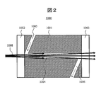
- FIG. 1 is a schematic perspective view of a flow cell having a cylindrical flow path
- FIG. 2 is a cross-sectional view of a cross section 1009 passing through the center of the optical path in FIG.
- the flow cell body 1001 is provided with window materials 1002 and 1003, and the sample solution introduced from the fluid introduction unit 1005 passes through the cylindrical channel 1004 and is discharged from the fluid discharge unit 1006.
- Measuring light 1008 is incident on the cylindrical channel 1004 from a light source, and light absorption and light emission occur.
- the refractive index fluctuation of the solution caused by external factors such as temperature fluctuation, pressure fluctuation, solution composition fluctuation, etc. fluctuates the ratio of these reflected light and scattered light to incident light, and apparent absorbance fluctuation, that is, noise Or the problem of being detected as drift is known.
- this effect is called a liquid lens effect because it is caused by a change in the refractive index of the solution inside the channel (Non-Patent Document 2). Therefore, in the cylindrical flow path, there is a trade-off relationship between the reduction in the spread of the position distribution of the sample and the improvement in sensitivity.
- Patent Document 3 a fluorine-based polymer, particularly Teflon (registered trademark) AF, which is a material having a lower refractive index than water, which is a solvent having the highest refractive index among frequently used in spectroscopic analysis, is flown.
- a system has been devised that achieves total reflection of light by applying to the inner walls of the road.
- Patent Document 4 a double fused silica capillary is used for the flow cell, a measuring solvent is used for the inner capillary, and a solvent having a lower refractive index than that, particularly a perfluoro solvent, is used for the outer capillary.
- a system has been devised in which light is totally reflected by the arrangement.
- the flow path expanded in a taper shape increases the flow cell capacity and the sample expands more than the cylindrical flow path, so the time that the sample stays in the flow path increases and the spread of the position distribution of the sample increases. End up.
- the amount of light decreases when the measurement flow channel is not fully reflected due to foreign matter adhesion etc. And sensitivity will fall.
- the present invention provides a flow cell that can improve the sensitivity while reducing the spread of the position distribution of the sample by devising the channel structure.
- a flow cell of a representative form of the present invention includes a main body having a sample flow path through which measurement light passes, and window materials provided on the light incident side and the light output side of the main body, and the sample flow path is a fluid. It has the 1st cylindrical flow path connected to the introduction part, and the 2nd cylindrical flow path connected to the fluid discharge part.
- the first cylindrical channel and the second cylindrical channel have a shape in which a cross-sectional area perpendicular to the incident optical axis is constant or continuously increases along the traveling direction of the incident light.
- the cross-sectional area perpendicular to the incident optical axis at the light exit end of the cylindrical flow path is equal to or smaller than the cross-sectional area perpendicular to the incident optical axis at the light incident end of the second cylindrical flow path.
- the cross-sectional area of the fluid discharge part is larger than the cross-sectional area of the fluid introduction part.
- the main body is made of a material that prevents reflection of light in the ultraviolet to infrared wavelength range, or the inner wall surfaces of the first and second channels prevent reflection of light in the ultraviolet to infrared wavelength range. It is preferably modified with a material having properties.
- the focal position of incident light from the light source is located closer to the light source than the fluid discharge side of the first cylindrical flow path.
- the amount of measurement light hitting the inner wall of the sample channel can be reduced and the sensitivity can be improved.
- the effect of rectifying the fluid is obtained by the first cylindrical channel, and the spread of the position distribution of the sample can be reduced because the sample flows quickly.
- Sectional drawing which shows an example of the flow cell by this invention Sectional drawing which shows an example of the flow cell by this invention. Sectional drawing which shows an example of the flow cell by this invention. Sectional drawing which shows an example of the flow cell by this invention. Sectional drawing which shows an example of the flow cell which has a flow path with an elliptical cross section. Sectional drawing which shows an example of the flow cell which has a polygonal cross section. Sectional drawing which shows an example of the flow cell by this invention. Sectional drawing which shows an example of the flow cell by this invention. Sectional drawing which shows an example of the flow cell by this invention. Sectional drawing which shows an example of the flow cell by this invention. Sectional drawing which shows an example of the flow cell by this invention. Sectional drawing which shows an example of the flow cell by this invention. Sectional drawing which shows an example of the flow cell by this invention. Sectional drawing which shows the other example of a fluid discharge part.
- Sectional drawing which shows the other example of a fluid discharge part. Sectional drawing which shows the other example of a fluid discharge part. Schematic which shows an example of a liquid chromatography apparatus. Schematic which shows an example of a spectrophotometer. Schematic which shows an example of a spectrophotometer. The figure which shows a band expansion measurement result. The figure which shows a noise measurement result.
- FIG. 4 is a schematic diagram of an embodiment of a flow cell according to the present invention.
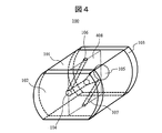
- the flow cell 100 includes a flow cell body 101 and window materials 102 and 103 that transmit two pieces of light. Inside the flow cell body 101, the first cylindrical flow path 104 on the measurement light incident side, the second cylindrical flow path 105 on the measurement light emission side, the fluid introduction part 106 for introducing fluid into the flow cell 100, and the fluid are discharged A fluid discharge portion 107 is provided.
- the light source is disposed on the first cylindrical flow path 104 side
- the detector is disposed on the second cylindrical flow path 105 side. Measurement light enters from the channel 104.
- the measurement light that has passed through the first cylindrical channel 104 and the second cylindrical channel 105 is detected by a detector.
- the sample solution is introduced from the fluid introduction unit 106, and is discharged from the fluid discharge unit 107 through the first cylindrical channel 104 and the second cylindrical channel 105.
- the window members 102 and 103 may be optical parts that transmit light, and may be optical parts such as quartz glass and lenses.
- the flow cell body 101 may be any material that prevents reflection of light in the ultraviolet to infrared wavelength region.
- black quartz is desirable, and a resin such as glass fiber reinforced polycarbonate mixed with carbon or a material such as carbon fiber may be used.
- the inner walls of the first cylindrical channel 104 and the second cylindrical channel 105 are modified by a method such as coating, plating, or vapor deposition with a material that prevents reflection of light in the ultraviolet to infrared wavelength region. May be.
- the flow cell body 101 may be a metal such as stainless steel or aluminum steel, a silicon oxide such as fused silica or quartz glass, or a resin such as polycarbonate.
- a material such as black quartz, zinc oxide, aluminum oxide, diamond-like carbon may be used.
- the outer shape of the flow cell shown in FIG. 4 has a shape obtained by cutting a part of a cylindrical shape for the convenience of installing a pipe for flowing a solution, but an important point is a cylindrical path through which fluid and measurement light pass. Therefore, it is not always necessary to have such a shape, for example, a simple cylindrical shape, a truncated cone shape, a rectangular tubular shape, a truncated cone shape, or a place where the flow cell should be placed based on these shapes.
- the shape processed in this way may be used.
- a method of forming the flow cell body 101 a method of drilling pores by drilling, a groove is formed on the surface of the cell body previously divided in half, and the surface is sufficiently polished by a chemical polishing method or the like, followed by optical bonding. There is a way to assemble the body.
- a method for forming the entire flow cell there are a method of mechanically pressing and a method of welding with heat.
- FIG. 5 is a cross-sectional view of the flow cell cut along a plane 408 passing through the flow path center of FIG.
- Two window members 102 and 103 are provided on both sides of the flow cell body 101, and a first cylindrical channel 104, a second cylindrical channel 105, and a first cylinder through which measurement light passes are provided inside the body.
- a fluid introduction part 106 for introducing a sample to the light incident end side of the cylindrical flow path 104 and a fluid discharge part 107 for discharging the sample from the light emission end side of the second cylindrical flow path are provided.
- the first cylindrical channel 104 has a cylindrical shape
- the second cylindrical channel 105 has a truncated cone shape whose cross-sectional area increases along the traveling direction of the measurement light emitted from the light source. It has the shape of The cross-sectional area of the light incident end of the second frustoconical channel 105 is equal to the cross-sectional area of the light exit end of the first cylindrical channel 104, and the focal position of light from the light source is the first cylindrical channel. 104 outside.
- the diameter of the cylindrical flow path 104 is 0.3 mm or more and 1 mm or less
- the total optical path length of the flow cell is 5 mm or more and 50 mm or less
- the cone angle of the truncated cone-shaped flow path 105 is 1 degree or more and 30 degrees.
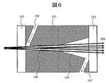
- the flow path diameters of the fluid introduction part 106 and the fluid discharge part 107 are the same and are preferably 0.2 mm or more and 0.5 mm or less. With such a shape, as shown in FIG. 6, not only can the sensitivity be improved by reducing the amount of measurement light 608 that strikes the inner wall of the flow path, but also the spread of the sample position can be reduced by the rectification effect. Become.
- the reflection / scattering Light is reduced by the material that prevents reflection of light in the ultraviolet to infrared wavelength region, which is adopted as a material for the entire flow cell or a modification material for the inner walls of the first and second channels, and can further improve sensitivity.
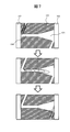
- FIG. 7 the conceptual diagram of the time-dependent change of a flow was shown. As shown in FIG. 7, the flow is adjusted by the first cylindrical flow path 104 acting as a fluid running section, and the sample does not expand in the second cylindrical flow path 105, so that the sample is quickly expanded. Since the residence time in the channel is reduced by flowing in the channel, it is possible to reduce the spread of the position distribution of the sample in the channel.
- the flow path diameters of the fluid introduction part 106 and the fluid discharge part 107 are preferably 0.2 mm or more and 0.5 mm or less.
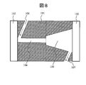
- the embodiment shown in FIG. 8 includes two window members 102 and 103 on both sides of the flow cell body 101, and a first cylindrical channel 104 and a second truncated cone shape through which measurement light passes inside the body.
- a flow path 105, a fluid introduction part 106, and a fluid discharge part 107 are provided.
- the second cylindrical channel 105 has a truncated cone shape equivalent to that of FIG. 5, and the cross-sectional area of the light incident end thereof is the first cylindrical channel. This is an example that is larger than the cross-sectional area of the light emitting end.
- the diameter of the cylindrical flow path 104 is 0.3 mm or more and 1 mm or less
- the total optical path length of the flow cell is 5 mm or more and 50 mm or less
- the cone angle of the truncated cone-shaped flow path 105 is 1 degree or more and 30 degrees. The following is preferred.
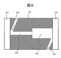
- FIG. 9 shows an embodiment in which the second cylindrical channel 105 is a cylindrical channel having a cross-sectional area larger than that of the first cylindrical channel 104. More specifically, the diameter of the first cylindrical channel 104 is 0.3 mm or more and 1 mm or less, the diameter of the second cylindrical channel 105 is 0.4 mm or more and 10 mm or less, and the total optical path length of the flow cell is 5 mm or more and 50 mm or less are preferable.
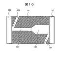
- FIG. 10 shows a connection portion between the second cylindrical channel 105 and the first cylindrical channel 104 based on the cylindrical channel having a cross-sectional area larger than that of the first cylindrical channel 104.
- An embodiment is shown in which the cross-sectional area changes so as to continuously expand in the vicinity.
- the diameter of the first cylindrical channel 104 is 0.3 mm or more and 1 mm or less
- the diameter of the second cylindrical channel 105 is 0.4 mm or more and 10 mm or less
- the total optical path length of the flow cell is 5 mm or more and 50 mm or less
- the length of the portion where the cross-sectional area of the second cylindrical flow path 105 continuously changes in the vicinity of the connecting portion with the first cylindrical flow path 104 is the first and second It is about 5 to 30% of the sum of the lengths of the cylindrical channels.
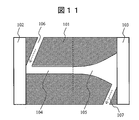
- FIG. 11 shows an embodiment in which the cross-sectional area of the second cylindrical channel 105 is changed so as to continuously expand along the streamline of the flow field inside the channel. More specifically, the diameter of the first cylindrical flow path 104 is 0.3 mm or more and 1 mm or less, and the diameter of the light emitting end of the second cylindrical flow path 104 is 0.4 mm or more and 10 mm or less. The total optical path length is preferably 5 mm or more and 50 mm or less.
- the shape of the second cylindrical flow path 105 a flow path in which the cross-sectional area of the entire flow path is continuously changing along the flow line of the flow field inside the flow path is taken as an example.
- the shape may be a parabolic shape or a hyperbolic shape, and a shape in which the cross-sectional area increases from the fluid introduction side to the fluid discharge side is desirable.
- the above-described cylindrical flow path has a rotationally symmetric shape with the central axis of the flow path as a rotation axis, but it does not necessarily have a rotationally symmetric shape, and an asymmetrical shape, for example, an asymmetric frustoconical flow It may be a road.
- the two flow paths having different shapes have been called the first cylindrical flow path and the second cylindrical flow path.
- the boundary of the cylindrical flow path can be defined as a position where the area of the cross section perpendicular to the incident optical axis or the increase rate of the area changes.
- the boundary between two flow paths is defined at the position where the area changes, in the flow cell of the embodiment shown in FIGS. 8 and 9, and the boundary between the two flow paths at the position where the area increase rate changes. Is defined in the flow cell of the embodiment shown in FIGS. 5, 10, and 11.
- the first cylindrical channel is limited to a cylindrical channel having a constant cross-sectional area, but the first cylindrical channel may not have a constant cross-sectional area.
- the same effect can be obtained even if both the first cylindrical channel 104 and the second cylindrical channel 105 are frustoconical channels.
- the cross-sectional area of the light exit end of the first cylindrical channel 104 is the second cylindrical channel 105 in order to prevent the measurement light from hitting the inner wall of the channel while having the function of adjusting the flow.
- the first cylindrical flow path 104 is a cylindrical flow path whose cross-sectional area slightly increases from the fluid introduction side to the fluid discharge side
- the channel 105 is preferably a cylindrical channel whose cross-sectional area increases from the fluid introduction side toward the fluid discharge side.
- the first cylindrical channel is a cylindrical channel
- the second cylindrical channel is a truncated cone-shaped channel or a shape along the flow line of the flow field inside the channel.
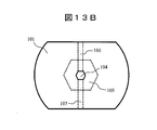
- FIGS. 13A and 13B are schematic sectional views of the flow cell as viewed from the window member 102 side.
- 13A and 13B are schematic sectional views of the flow cell as viewed from the window member 102 side.
- the sensitivity can be further improved by adjusting the optical system of the liquid analyzer or changing the arrangement of the flow cell.
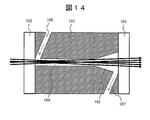
- FIG. 6 shows an example in which the focus position of the measurement light is arranged outside the flow cell.
- the focus position of the measurement light is inside the flow cell, that is, inside the first cylindrical channel 104 as shown in FIG. It may be arranged.
- the ratio of the optical path length of the first cylindrical channel 104 and the optical path length of the second cylindrical channel 105 to the total optical path length of the flow cell is limited by the focal position of the measurement light. It is desirable to optimize in view of the position expansion of the internal sample.
- the measurement light from the light source is preferably as narrow as possible and has a smaller incident angle.
- a material that absorbs ultraviolet, visible, and infrared light is used for the flow cell body in order to prevent random scattering and absorption of the measurement light on the inner wall of the flow path. Is desirable.
- a cylindrical flow path is often used as the shape of the fluid introduction part and the fluid discharge part, and a Z shape (a shape that enters obliquely with respect to the optical path) or a crank shape is often used together with the optical path portion. .
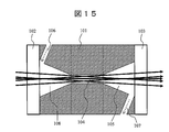
- FIG. 15 shows an embodiment of a flow cell in which a third cylindrical channel is newly added to the first and second cylindrical channels on the light source side.
- Two window members 102 and 103 are provided on both sides of the flow cell body 101, and a truncated cone-shaped channel 108, which is a third channel through which measurement light passes, and a first cylindrical channel are provided inside the body.
- a cylindrical channel 104 and a truncated cone channel 105 which is a second cylindrical channel are continuously formed.
- a fluid introduction part 106 is connected to the light incident end of the third flow path 108, and a fluid discharge part 107 is connected to the light emission end of the second cylindrical flow path 105.
- This channel structure has a structure in which a truncated cone channel whose sectional area continuously decreases with respect to the traveling direction of the measurement light is newly added to the light source side of the channel structure shown in FIG. More specifically, the diameter of the cylindrical channel 104 is 0.3 mm or more and 1 mm or less, the total optical path length of the flow cell is 10 mm or more and 60 mm or less, and the cone angle of the frustoconical channels 105 and 108 is 1 degree or more.
- the flow path diameter of the fluid introduction part 106 and the fluid discharge part 107 is preferably 0.2 mm or more and 0.5 mm or less at 30 degrees or less. At this time, it is desirable that the focus position of the measurement light from the light source is arranged on the fluid introduction side rather than the fluid discharge side of the first cylindrical channel 104 as shown in FIG.
- the flow path through which the measurement light of the entire flow cell passes is composed of three or more cylindrical flow paths, in order to maximize the effects of the present invention, Starting from the site with the smallest cross-sectional area, the flow path on the fluid discharge side of the site has a shape in which the cross-sectional area continuously increases in the direction of travel of the measurement light.
- the flow path on the introduction side has a shape in which the cross-sectional area continuously decreases with respect to the traveling direction of the measurement light, and the focal position of the measurement light has the smallest cross-sectional area among the flow paths of the entire flow cell. It is desirable that the fluid is disposed on the fluid introduction side rather than the fluid discharge side of the part.
- FIG. 16 to FIG. 21 show an embodiment of a flow cell having various fluid discharge portions that enable such an effect, by a cross-sectional view at the same position as FIG.
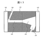
- FIG. 16 shows an embodiment of a flow cell having a flow path having the same shape as in FIG. 5 and having a cross-sectional area of the fluid discharge part 107 that is equal to or larger than a cross-sectional area of the fluid introduction part 106.
- the ratio is equal to or greater than the ratio of the maximum cross-sectional area of the channel 105. More specifically, the diameter of the cylindrical flow path 104 is 0.3 mm or more and 1 mm or less, the total optical path length of the flow cell is 5 mm or more and 50 mm or less, and the cone angle of the truncated cone-shaped flow path 105 is 1 degree or more and 30 degrees.
- the flow path diameter of the fluid introduction part 106 is preferably 0.2 mm or more and 0.5 mm or less, and the flow path diameter of the fluid discharge part 107 is preferably 0.2 mm or more and 3.0 mm or less.
- the cross section of the fluid discharge unit 107 may be circular, elliptical, or polygonal.
- this effect can also be obtained by expanding the cross-sectional area of only a part of the channel on the side connected to the second cylindrical channel 105 in the fluid discharge unit 107.
- the cross-sectional area is expanded only to a part of the flow path of the fluid discharge section, so that connection of piping and the like are facilitated.
- this effect can be achieved by providing not only one fluid discharge part but also two or more.
- the total cross-sectional area of the plurality of fluid discharge portions may be larger than the cross-sectional area of the fluid introduction portion.
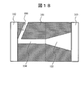
- FIG. 18 shows an embodiment of a flow cell having a flow path of the same shape as in FIG. 5 and having two fluid discharge portions, and shows a cross-sectional view at the same position as in FIG.
- FIG. 19 shows a view of the flow cell of this embodiment viewed from the window member 103 side, and the two fluid discharge portions 107a and 107b are arranged at positions symmetrical with respect to the axis of the flow path.
- FIG. 20 shows an embodiment of a flow cell having three flow outlets 107a to 107c having flow paths of the same shape as in FIG. 5 and arranged symmetrically with respect to the flow path axis, and FIG. FIG.
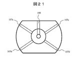
- FIG. 20 shows an embodiment of a flow cell in which fluid discharge portions 107a to 107d are arranged at positions symmetrical to each other with respect to the axis of the flow path, and is a view of the flow cell viewed from the same direction as FIG. 18 to 21, specifically, the diameter of the cylindrical channel 104 is 0.3 mm or more and 1 mm or less, the total optical path length of the flow cell is 5 mm or more and 50 mm or less, and the cone angle of the frustoconical channel 105 is 1.
- the flow path diameter of the fluid introduction part 106 and each fluid discharge part 107 is preferably 0.2 mm or more and 3.0 mm or less.
- the structure for increasing the fluid replacement efficiency mentioned above is based on the flow path structure shown in FIG. 5, but based on the flow path structure shown in FIGS. 8 to 12, 14, and 15.
- the same effect can be obtained.
- the same effect can be obtained even if the cross-sectional area of the fluid discharge portion is made larger than the cross-sectional area of the fluid introduction portion based on the cylindrical flow passage or the flow passage having the whole flow passage tapered.
- the flow channel structure of FIG. 5 or FIG. 11 is used. It is desirable to make it.
- the flow cell according to the present invention is incorporated in a liquid analyzer represented by flow injection analysis, liquid chromatography, or the like, and is used for spectroscopic analysis of a sample by light absorption or light emission.
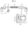
- FIG. 22 to FIG. 24 are explanatory diagrams when the flow cell according to the present invention is incorporated in a liquid analyzer.
- FIG. 22 shows a flow path system of the liquid chromatograph apparatus.
- the eluent is sent from the eluent tank 2201 by the pump 2202 and supplied to the separation column 2204 through the sample introduction unit 2203.
- a sample containing a test component is introduced from an injector 2205, separated by a separation column 2204, passed through a spectrophotometer 2206, and discharged into a waste liquid tank 2207.
- the spectrophotometer 2206 is connected to the control unit 2208.
- the control unit 2208 for example, a personal computer (PC) as shown in FIG. 22 can be used.
- the PC includes a data display device 2209 and a data processing device 2210.
- the data processing device 2210 includes, for example, an arithmetic device 2211, a temporary storage device 2212, and a nonvolatile storage device 2213.
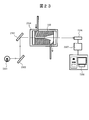
- FIG. 23 shows an optical system capable of single wavelength detection of the spectrophotometer 2206 in FIG.
- the flow cell 100 has the structure shown in FIG. 17, and has a light incident window 102 at one end of the flow cell body 101 and a light exit window 103 at the other end.
- the light from the light source 2301 passes through the condensing mirror 2302, and then is dispersed by the diffraction grating 2303, and a specific monochromatic light is irradiated to the first cylindrical flow path 104 in the flow cell 100 fixed by the jig 2304. .
- the solution containing the separated sample eluted from the separation column 2204 is supplied from the fluid introduction unit 106 to the flow cell 100, passes through the first cylindrical channel 104 and the second cylindrical channel 105, and then the fluid discharge unit. 107 is discharged.
- the light transmitted through the first cylindrical channel 104 and the second cylindrical channel 105 is received by the photodetector 2306, and the received light signal is converted into absorbance by the detection circuit 2307 connected to the control unit 2308.
- the As the light source 2301 an arbitrary light source that can provide light in an appropriate band including a deuterium lamp or a halogen lamp is used.
- the photodetector 2306 a photodetector capable of detecting single wavelength light such as a silicon photodiode is used. In order to enhance the effect of the present invention, the optical system was adjusted so that the focus position of the measurement light emitted from the light source was set on the fluid introduction side rather than the fluid discharge side of the first cylindrical channel 104.
- FIG. 24 is a schematic diagram showing an optical system capable of multi-wavelength detection, which is an example of a liquid analyzer having another form of spectrophotometer.
- the flow cell 100 has the same configuration as that shown in FIG. 17, and has a light entrance window 102 at one end of the flow cell body 101 and a light exit window 103 at the other end.
- the light from the light source 2401 passes through the condensing mirror 2402 and then irradiates the first cylindrical flow path 104 in the flow cell 100 fixed by the jig 2403.
- the solution containing the separated sample eluted from the separation column 2204 is supplied to the flow cell 100 from the fluid introduction unit 106, passes through the first cylindrical channel 104 and the second cylindrical channel 105, and then the fluid discharge unit.
- the light transmitted through the first cylindrical flow path 104 and the second cylindrical flow path 105 passes through the condenser mirror 2405 and then is received by the photodetector 2407 via the diffraction grating 2406. It is converted into absorbance by a detection circuit 2408 connected to the control unit 2409.
- the light source 2401 an arbitrary light source that can provide light in an appropriate band including a deuterium lamp or a halogen lamp is used.
- the photodetector 2407 a photodetector capable of detecting multiple wavelengths such as a photodiode array is used.
- the optical system was adjusted, and the focal position of the measurement light emitted from the light source was arranged on the fluid introduction side rather than the fluid discharge side of the first cylindrical channel 104.
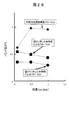
- FIG. 25 shows experimental results comparing the band expansion of the flow cell based on the present invention and the flow cell having the conventional frustoconical channel structure.
- the flow cell according to the present invention the flow cell shown in FIGS. 5 and 17 was used. Further, as a comparative example, the flow cell having the conventional truncated cone cylindrical structure shown in FIG.
- the diameter of the light incident end of the frustoconical channel 1007 shown in FIG. 3 is the same as the diameter of the light incident end of the first cylindrical channel 104 shown in FIGS.
- the diameter of the light exit end is the same as the diameter of the light exit end of the second frustoconical channel 105 shown in FIGS.
- the eluent is methanol
- the flow rate is 1 mL / min
- the measurement wavelength is 250 nm
- a benzene 0.01% methanol solution is added to the sample.
- the band expansion of each flow cell was measured.
- the band spread of each flow cell was expressed as a relative value, assuming that the band spread at the flow rate of the flow cell of the comparative example was 0.5 mL / min.
- the band expansion of the flow cell of the embodiment shown in FIG. 5 is smaller than that of the comparative flow cell having a frustoconical channel structure designed to have the same sensitivity. It was.
- the conventional cylindrical flow path is changed to a flow path structure including a first cylindrical flow path and a second cylindrical flow path, and the second cylindrical flow path is perpendicular to the incident optical axis.
- the cross-sectional area is constant or increases continuously in the traveling direction of incident light, and the cross-sectional area perpendicular to the incident optical axis at the light exit end of the first cylindrical flow path is the second cylindrical flow.
- FIG. 25 in addition to the flow channel structure of FIG. 5 as shown in FIG. 17, if a flow cell having a fluid discharge section with a large cross-sectional area is used, the time for the sample to stay in the flow channel is reduced, and the band is expanded. It was found that can be further reduced. Further, instead of the flow cell shown in FIG. 17, the flow cell shown in FIG. 16 and the flow cell having a plurality of fluid discharge portions shown in FIGS. As a result, it was confirmed that the same effect as the flow cell shown in FIG. 17 was obtained.
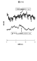
- FIG. 26 shows the experimental results of noise comparison between the flow cell according to the present invention and the flow cell having the cylindrical flow channel structure of the comparative example.
- the flow cell shown in FIG. 17 was used as the flow cell according to the present invention.
- a flow cell having the conventional cylindrical flow channel shown in FIG. 2 designed so that the optical path length and the band spread are the same was used as a comparative example. That is, a flow cell in which the diameter of the cylindrical channel 1004 shown in FIG. 2 is the same as the diameter of the light incident end of the first cylindrical channel 104 shown in FIG. 17 was used.
- the eluent was methanol, and noise at a wavelength of 250 nm at a flow rate of 1 mL / min was examined using each flow cell.
- the flow cell according to the present invention has a reduced noise due to the reduced amount of light hitting the inner wall of the flow path as compared with the flow cell having the cylindrical flow path structure of the comparative example.
- experiments were performed under the same conditions using the flow cell according to the present invention shown in FIGS. 5, 8 to 12, 14 to 16, and 18 to 21. However, the same effect was confirmed. Therefore, it has been confirmed by experiments that the use of the flow path structure shown in the present invention can achieve both reduction in the position expansion of the sample and improvement in sensitivity.
- FIGS. 25 and 26 are similar to those obtained when the experiment was performed under the same conditions using the liquid chromatography apparatus shown in FIG. 22 having the spectrophotometer shown in FIG. It was confirmed that it was obtained.
- this invention is not limited to the above-mentioned Example, Various modifications are included.
- the above-described embodiments have been described in detail for easy understanding of the present invention, and are not necessarily limited to those having all the configurations described.
- a part of the configuration of one embodiment can be replaced with the configuration of another embodiment, and the configuration of another embodiment can be added to the configuration of one embodiment.
Landscapes
- Physics & Mathematics (AREA)
- Biochemistry (AREA)
- Health & Medical Sciences (AREA)
- Life Sciences & Earth Sciences (AREA)
- Chemical & Material Sciences (AREA)
- Analytical Chemistry (AREA)
- General Health & Medical Sciences (AREA)
- General Physics & Mathematics (AREA)
- Immunology (AREA)
- Pathology (AREA)
- Spectroscopy & Molecular Physics (AREA)
- Optical Measuring Cells (AREA)
- Investigating Or Analysing Materials By Optical Means (AREA)
Abstract
流路構造の工夫により試料の位置分布拡がりを低減しつつ、感度を向上させたフローセルを提供する。 測定光が通過する第一の筒状流路104と第二の筒状流路105を備える。第一の筒状流路及び第二の筒状流路は入射光軸に垂直な断面積が一定又は入射光の進行方向へ連続的に増加している形状であり、第一の筒状流路の光出射端における断面積が第二の筒状流路の光入射端における断面積以下である。第一の筒状流路には流体導入部106から試料が導入され、第二の筒状流路を通った試料は流体排出部107から排出される。好ましくは、流体排出部の流路断面積が流体導入部の流路断面積より大きく、フローセル本体101が紫外から赤外の波長域の光の反射を防止する材質で作製されている。
Description
本発明は、試料を分光分析するためのフローセルに関し、特に液体分析装置に用いられる分光分析用フローセルに関する。
液体クロマトグラフ装置等に代表される液体分析装置に備えられて紫外・可視・赤外光で試料を分光分析する装置にはフローセルが設けられ、フローセルを用いて吸光度あるいは蛍光に代表される発光強度等が測定される。一般には、フローセル内の光路長が長いほど分析感度は高くなる。しかし、長光路長を有するフローセルでは、しばしば流体力学的効果によってフローセル内で試料の位置分布が拡がるため、得られるピークシグナル値が本来得られるべきピークシグナル値よりも減少し、感度の低下をもたらす。液体クロマトグラフ装置のように溶液中に共存する複数の試料成分を分離・分析する目的の場合には、この試料の位置分布の拡がりは感度の低下だけでなく同時に分離能の低下をもたらす。
フローセルは、加工及びその理論的取り扱いの容易さから円筒状流路を有するものが良く使用される。その典型的な構造は図1及び図2に示す通りである。図1は、円筒状流路を有するフローセルの概略斜視図、図2は図1の光路中心を通る断面1009の断面図である。フローセルボディ1001には窓材1002,1003が備えられ、流体導入部1005から導入された試料溶液は、円筒状流路1004を通り、流体排出部1006から排出される。円筒状流路1004には光源より測定光1008が入射され、吸光や発光現象が生じる。この円筒状流路を有するフローセル1000において、試料位置分布の拡がりを低減するために流路径を小さくすることが試みられている。しかし、流路径の縮小は、一般的にフローセルの入射面で遮光される測定光量の増加につながるだけでなく、図2に示すように、長光路長を有する円筒状流路においては流路内壁に当たる測定光量の増加にもつながり、得られるシグナル値が減少又はノイズが増加し感度が低下するという問題が発生する。殊に吸光度法を原理とする場合、流路内壁に当たった測定光は無秩序な光反射・光散乱や光吸収となって、ノイズの増加をもたらすことがしばしばある(非特許文献1)。すなわち温度変動、圧力変動、溶液の組成変動等といった外的要因によって生じた溶液の屈折率変動が、入射光に対するこれらの反射光や散乱光の比率を変動させ、みかけ上の吸光度の変動すなわちノイズ又はドリフトとして検出されるという問題が知られる。特にこの効果は、流路内部の溶液の屈折率変動が原因であることから液体レンズ効果と呼ばれる(非特許文献2)。したがって、円筒状流路では、試料の位置分布拡がりの低減と感度の向上はトレードオフの関係にある。
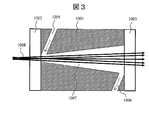
この問題を解決するため、大別して2種類の手法が考案されてきた。一つは流路構造の変更により流路内壁に当たる測定光量を抑制する手法であり、もう一つは材料学的工夫により流路内壁で測定光を全反射させる手法であり、それぞれ感度を改善しようという試みである。前者の例として、図3に示したように、円筒状流路の代わりに入射面から出射面に対してテーパー状に広がっている円錐台状流路1007を使用することが考案されている(特許文献1)。後者の例として、ガラスキャピラリをフローセル材質とし、ガラスより屈折率の高い溶媒を用いることが考案されている(特許文献2)。また、特許文献3には、分光分析に頻繁に用いられる中で最も屈折率の高い溶媒である水よりも低い屈折率を有する材料であるフッ素系高分子、特にテフロン(登録商標)AFを流路内壁に塗布することで、光の全反射を達成する方式が考案されている。さらに、特許文献4には二重の溶融シリカキャピラリをフローセルに用いて、内側のキャピラリには測定溶媒を、外側のキャピラリにはそれよりも低い屈折率を有する溶媒、特にパーフルオロ系溶媒をそれぞれ配置することによって光を全反射させる方式が考案されている。
J.Chromatogr.465,227(1989)
J.Chromatogr.503,127(1990)
テーパー状に拡げた流路は、円筒状流路と比較してフローセル容量が増加して試料がより拡がるため、試料が流路内に滞留する時間が増大し、試料の位置分布拡がりが増加してしまう。一方、材料学的工夫により流路内で測定光を全反射させることでシグナル対ノイズ比を改善しようという試みでは、測定流路内部が異物付着などによって全反射条件でなくなった場合、光量が減少し、感度が低下してしまう。
本発明は、流路構造の工夫により試料の位置分布拡がりを低減しつつ、感度を向上できる、フローセルを提供するものである。
本発明の代表的な形態のフローセルは、測定光が通過する試料流路を有する本体と、前記本体の光入射側と光出射側に設けられた窓材とを備え、試料流路は、流体導入部に接続された第一の筒状流路と流体排出部に接続された第二の筒状流路とを有する。第一の筒状流路及び第二の筒状流路は入射光軸に垂直な断面積が一定又は入射光の進行方向に沿って連続的に増加している形状であり、第一の筒状流路の光出射端における入射光軸に垂直な断面積が、第二の筒状流路の光入射端における入射光軸に垂直な断面積以下である。
好ましくは、流体排出部の流路断面積が流体導入部の流路断面積より大きい。本体は紫外から赤外の波長域の光の反射を防止する材質で作製されている、あるいは、第一及び第二の流路内壁表面が紫外から赤外の波長域の光の反射を防止する性質を有する材質で修飾されているのが好ましい。
また、本発明のフローセルを組み込んだ液体分析装置は、光源からの入射光の焦点位置が第一の筒状流路の流体排出側よりも光源側に位置するのが望ましい。
測定光が通過する試料流路を2つの筒状流路を連結して構成することにより、試料流路の内壁に当たる測定光量が低減し、感度を向上させることができる。加えて、第一の筒状流路によって流体を整流させる効果が得られ、迅速に試料が流れることで試料の位置分布拡がりを低減させることができる。
上記した以外の、課題、構成及び効果は、以下の実施形態の説明により明らかにされる。
以下、図面を参照して本発明の実施の形態を説明する。
図4は、本発明によるフローセルの一実施例の概略図である。このフローセル100は、フローセルボディ101と2個の光を透過させる窓材102,103を備える。フローセルボディ101内部には、測定光入射側の第一の筒状流路104、測定光出射側の第二の筒状流路105、流体をフローセル100に導入する流体導入部106、流体が排出される流体排出部107が設けられている。後述するように、フローセル100を液体分析装置に組み込む際には、光源は第一の筒状流路104側に、検出器は第二の筒状流路105側に配置され、第一の筒状流路104から測定光が入射する。第一の筒状流路104及び第二の筒状流路105を通過した測定光は検出器で検出される。試料溶液は流体導入部106から導入され、第一の筒状流路104と第二の筒状流路105を経て、流体排出部107から排出される。
窓材102,103は光を透過させる光学部品であればよく、例えば石英ガラスやレンズのような光学部品であればよい。フローセルボディ101は紫外から赤外の波長域の光の反射を防止する材質であればよい。例えば黒色石英が望ましく、カーボンが混合されたグラスファイバー強化ポリカーボネートのような樹脂、炭素繊維のような材質でもよい。また、第一の筒状流路104及び第二の筒状流路105の内壁を、紫外から赤外の波長域の光の反射を防止する材質で塗布又はメッキ、蒸着等の方法により修飾してもよい。その場合、フローセルボディ101は、例えばステンレス鋼やアルミ鋼等の金属や、溶融シリカや石英ガラス等のシリコン酸化物、ポリカーボネートのような樹脂でもよく、流路内壁に修飾されるべき材質は、例えば黒色石英、酸化亜鉛、酸化アルミニウム、ダイアモンドライクカーボン等のような材質とすればよい。
図4に示したフローセルの外形は、溶液を流す配管を設置する都合上、円筒状形状の一部を切り取った形状をしているが、重要な点は流体及び測定光が通過する筒状路にあるため、必ずしもこのような形状である必要はなく、例えば単純な円筒状、円錐台筒状、方形筒状、方錐台筒状もしくはこれらを基にフローセルを配置すべき場所に設置しやすいように加工された形状でもよい。フローセルボディ101の形成方法としては、ドリル加工で細孔を開ける方法や、予め半分に分割されたセルボディ表面にドリルで溝を形成し、化学研磨法等で表面を十分に研磨した後、光学接着によりボディを組み立てる方法がある。フローセル全体の形成方法としては、機械的に圧着させる方法や熱で溶着させる方法がある。
図5は、図4の流路中心を通る面408に沿って切断したフローセルの断面図である。フローセルボディ101の両脇に2個の窓材102,103が備えられ、ボディ内部には測定光が通過する第一の筒状流路104及び第二の筒状流路105、第一の筒状流路104の光入射端側に試料を導入する流体導入部106、第二の筒状流路の光出射端側から試料を排出する流体排出部107が設けられている。本実施例では、第一の筒状流路104は円筒状の形状、第二の筒状流路105は光源から出射された測定光の進行方向に沿って断面積が増加する円錐台筒状の形状をしている。第二の円錐台状流路105の光入射端の断面積は第一の円筒状流路104の光出射端の断面積と等しく、光源からの光の焦点位置は第一の筒状流路104の外部にある。
より具体的には、円筒状流路104の直径は0.3mm以上、1mm以下、フローセルの総光路長は5mm以上、50mm以下、円錐台状流路105の円錐角は1度以上、30度以下、流体導入部106及び流体排出部107の流路径は同一であり、0.2mm以上、0.5mm以下が好ましい。このような形状により、図6に示したように、流路内壁に当たる測定光608の量を低減して感度を向上できるのみならず、整流効果により試料の位置拡がりをも低減することが可能になる。セルボディの材質あるいは第一及び第二の流路内壁の材質を選択することで、第一あるいは第二の流路内壁で微小量の測定光が無秩序に反射・散乱したとしても、その反射・散乱光はフローセル全体の材質ないし第一及び第二の流路内壁の修飾材質として採用された紫外から赤外の波長域の光の反射を防止する材質によって低減され、更に感度を向上させることができる。図7に、流れの経時変化の概念図を示した。図7に示したように、第一の筒状流路104が流体の助走区間として働くことで流れが整えられ、第二の筒状流路105内においても試料が拡がらず、試料が迅速に流れることによって流路内部での滞留時間が低減されるため、流路内部での試料の位置分布拡がりを低減することが可能となる。
図8から図12に、様々な流路形状を有するフローセルの別の実施例を、図5と同様な位置での断面図で示す。各実施例において、流体導入部106及び流体排出部107の流路径は、0.2mm以上、0.5mm以下が好ましい。
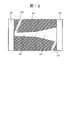
図8に示した実施例は、フローセルボディ101の両脇に2個の窓材102,103を備え、ボディ内部に測定光が通過する第一の円筒状流路104及び第二の円錐台状流路105、流体導入部106、流体排出部107を有する。図8に示した実施例は、第二の筒状流路105が図5と同等の円錐台筒状の形状をしており、かつその光入射端の断面積は第一の筒状流路の光出射端の断面積より大きい例である。より具体的には、円筒状流路104の直径は0.3mm以上、1mm以下、フローセルの総光路長は5mm以上、50mm以下、円錐台状流路105の円錐角は1度以上、30度以下が好ましい。
図9は、第二の筒状流路105が第一の円筒状流路104の断面積より大きい断面積を有する円筒状流路である実施例を示している。より具体的には、第一の円筒状流路104の直径は0.3mm以上、1mm以下、第二の円筒状流路105の直径は0.4mm以上、10mm以下、フローセルの総光路長は5mm以上、50mm以下が好ましい。
図10は、第二の筒状流路105が第一の円筒状流路104の断面積より大きい断面積を有する円筒状流路を基として、第一の筒状流路104との連結部近傍で断面積が連続的に拡大するように変化している実施例を示している。より具体的には、第一の円筒状流路104の直径は0.3mm以上、1mm以下、第二の円筒状流路105の直径は0.4mm以上、10mm以下、フローセルの総光路長は5mm以上、50mm以下、第一の筒状流路104との連結部近傍で第二の筒状流路105の断面積が連続的に変化している部分の長さは第一及び第二の筒状流路の長さの和の5~30%程度である。
図11は、第二の筒状流路105の断面積が流路内部の流れ場の流線に沿って連続的に拡大するように変化している実施例を示す。より具体的には、第一の円筒状流路104の直径は0.3mm以上、1mm以下、第二の筒状流路104の光出射端の直径は0.4mm以上、10mm以下、フローセルの総光路長は5mm以上、50mm以下が好ましい。本実施例では、第二の筒状流路105の形状として流路全体の断面積が流路内部の流れ場の流線に沿って連続的に変化している流路を例に挙げたが、その形状は放物線状、双曲線状といった形状でもよく、流体導入側から流体排出側に向かって断面積が増加している形状が望ましい。
図8から図11に示したような流路形状にすることで、図5の場合と同様に、流路内壁に当たる測定光量を低減して感度向上を図り、同時に、流路内部での滞留時間を低減して流路内部での試料の位置分布拡がりの低減を図ることができる。尚、上に挙げた筒状流路は流路中心軸を回転軸とした回転対称な形状としたが、必ずしも回転対称な形状である必要はなく、非対称な形状、例えば非対称な円錐台状流路でもよい。これまでに挙げた例の中で、形状の異なる二つの流路を第一の筒状流路及び第二の筒状流路と呼んできたが、第一の筒状流路と第二の筒状流路の境界は、その入射光軸に垂直な断面の面積又は面積の増加率が変化する位置として定義することができる。例えば、面積の変化する位置で2つの流路の境界が規定されるのは図8、図9に示した実施例のフローセルであり、面積の増加率が変化する位置で2つの流路の境界が規定されるのは図5、図10、図11に示した実施例のフローセルである。
以上は、第一の筒状流路が断面積一定の円筒状流路に限定された実施例であるが、第一の筒状流路は断面積が一定でなくともよい。例えば、図12に示すように、第一の筒状流路104及び第二の筒状流路105が共に円錐台状流路であっても同じ効果が得られる。この場合、流れを整える機能を有した上で、流路内壁へ測定光が当たらなくするために、第一の筒状流路104の光出射端の断面積は第二の筒状流路105の光入射端の断面積以下という条件下で、第一の筒状流路104は流体導入側から流体排出側に向かって断面積がわずかに増加する筒状流路、第二の筒状流路105は流体導入側から流体排出側に向かって断面積が増加する筒状流路であることが望ましい。
図5から図12を用いて説明したように、試料の位置分布拡がりの低減と感度向上を両立できる流路構造には様々な形状があり得るが、流体力学的効果による試料の位置分布拡がりを考慮すれば、第一の筒状流路は円筒状流路、第二の筒状流路は円錐台状流路もしくは流路内部の流れ場の流線に沿った形状が望ましい。
尚、光の進行方向に垂直な流路断面は円形である必要はなく、図13A、図13Bに示すように楕円形状や多角形状でも同じ効果が得られる。図13A及び図13Bは、窓材102側からフローセルを見た断面摸式図である。特に楕円状の流路断面とすると、光スポットが楕円状の拡がりを有するハロゲンランプのような光源を用いた場合に、流路内壁に当たる測定光の量を低減することができる。また、液体分析装置の光学系の調整やフローセルの配置を変更することで、感度を更に向上することが可能となる。すなわち、光源からの測定光の焦点位置が第一の筒状流路の流体排出側よりも光源側に配置されていれば、第一の筒状流路の内壁あるいは第二の筒状流路の内壁に当たる測定光を低減することができる。図6には測定光の焦点位置がフローセル外部に配置されている例を示したが、測定光の焦点位置は、図14に示すようにフローセル内部すなわち第一の筒状流路104の内部に配置されていてもよい。この時、フローセルの総光路長に対する第一の筒状流路104の光路長と第二の筒状流路105の光路長の割合は、この測定光の焦点位置により制限されるが、流路内部の試料の位置拡がりとの兼ね合いで最適化されることが望ましい。
尚、光源からの測定光は可能な限り細く絞られ、かつ入射角が小さい程望ましい。本発明による感度の向上をより確実にするためには、流路内壁での測定光の無秩序な散乱・吸収を防ぐために、フローセルボディには紫外・可視・赤外光を吸収する材質を用いることが望ましい。流体導入部及び流体排出部の形状としては円筒状流路が良く用いられ、光路部分と合わせてZ形の形状(光路に対して斜めに侵入する形状)ないしクランク形の形状が良く利用される。以上は、流体導入部・流体排出部・流路が同じ平面上に存在する例であるが、流路・流体導入部が存在する平面と流路・流体排出部が存在する平面がなす角が任意の角度を形成するようにそれぞれ配置されていてもよい。
また、更なる長光路長時に上述した課題に加え、絶対的な光量が不足することが懸念されるが、これを克服するためにはフローセル全体の流路を3つ以上の筒状流路から構成してもよい。図15に、第一、第二の筒状流路に、新たに光源側に第三の筒状流路を加えたフローセルの実施例を示す。フローセルボディ101の両脇に2個の窓材102,103を備え、ボディ内部には測定光が通過する第三の流路である円錐台状流路108、第一の筒状流路である円筒状流路104及び第二の筒状流路である円錐台状流路105が連続して形成されている。第三の流路108の光入射端には流体導入部106が接続され、第二の筒状流路105の光出射端には流体排出部107が接続されている。この流路構造は、図5に示した流路構造の光源側に新たに断面積が測定光の進行方向に対して連続的に減少する円錐台状流路を追加した構造となっている。より具体的には、円筒状流路104の直径は0.3mm以上、1mm以下、フローセルの総光路長は10mm以上、60mm以下、円錐台状流路105,108の円錐角は1度以上、30度以下、流体導入部106及び流体排出部107の流路径は0.2mm以上、0.5mm以下が好ましい。この時、光源からの測定光の焦点位置は、図15に示すように第一の筒状流路104の流体排出側よりも流体導入側に配置されていることが望ましい。
この構成により、更なる長光路長を有するフローセルにおいても図5から図14で説明したフローセルと同様の効果と絶対的光量の確保により、試料の位置分布拡がりの低減と感度向上を両立することができる。尚、フローセル全体の測定光が通過する流路が3つ以上の筒状流路から構成されている場合、本発明の効果を最大限に発揮するためには、フローセル全体の流路の中で最も断面積の小さい部位を基点として、その部位よりも流体排出側にある流路はその断面積が測定光の進行方向に対して連続的に増加している形状であり、その部位よりも流体導入側にある流路はその断面積が測定光の進行方向に対して連続的に減少している形状であり、かつ測定光の焦点位置がフローセル全体の流路の中で最も断面積の小さい部位の流体排出側よりも流体導入側に配置されていることが望ましい。
ここまでに述べた流路構造だけでも、従来のテーパー状の流路構造と比較して試料の位置分布拡がりの低減と感度向上を達成することは可能である。しかし、既に述べた構造では第二の筒状流路105を拡げたものの、流体排出部107の流路径は狭いままであるために、流体排出部107付近において試料が流れにくい状態となっている。したがって、更なる試料の位置分布拡がりの低減を図るためには、流体排出部の構造工夫による流体の置換効率を高めることが望ましい。図16から図21に、そのような効果を可能にする様々な流体排出部を有するフローセルの実施例を、図5と同様の位置での断面図によって示す。
図16は、図5と同じ形状の流路を有し、流体排出部107の断面積が流体導入部106の断面積以上であるフローセルの実施例を示している。このように流体排出部107の断面積を大きくすることにより、流路内に残留した試料の置換を早めることが可能となる。質量の保存則を考慮すれば、この流体導入部106の流路断面積に対する流体排出部107の流路断面積の比は、第一の筒状流路104の最小断面積に対する第二の筒状流路105の最大断面積の比以上であることが望ましい。より具体的には、円筒状流路104の直径は0.3mm以上、1mm以下、フローセルの総光路長は5mm以上、50mm以下、円錐台状流路105の円錐角は1度以上、30度以下、流体導入部106の流路径は0.2mm以上、0.5mm以下、流体排出部107の流路径は0.2mm以上、3.0mm以下が好ましい。流体排出部107の流路断面は、円状・楕円状・多角形状であればよい。尚、図17に示すように、この効果は流体排出部107における第二の筒状流路105に接続された側の流路の一部のみの断面積を拡げることによっても得られる。このように断面積を拡げるのを流体排出部の流路の一部のみにすることで、配管の接続等が容易となる。
また、この効果は、流体排出部を1つだけでなく、2つ以上設けることによっても達成される。すなわち、複数設けた流体排出部の総断面積が流体導入部の断面積以上であればよい。その場合、流体の置換効率を最大限に高めるためには、同じ流路径を有する複数の流体排出部を、測定光の進行方向に対して垂直な断面内において対称な位置に配置することが望ましい。
図18は、図5と同じ形状の流路を有し流体排出部が2つ備えられたフローセルの実施例を示すもので、図5と同様の位置での断面図を示している。図19は、窓材103側から本実施例のフローセルを見た図を示しており、2つの流体排出部107a,107bは流路の軸に対して対称な位置に配置されている。図20は、図5と同じ形状の流路を有し流路の軸に対して対称な位置に配置された3つの流体排出部107a~107cを有するフローセルの実施例、図21は、4つの流体排出部107a~107dが流路の軸に対して互いに対称な位置に配置されたフローセルの実施例を示し、図19と同様の方向からフローセルを見た図である。図18~図21において、具体的には円筒状流路104の直径は0.3mm以上、1mm以下、フローセルの総光路長は5mm以上、50mm以下、円錐台状流路105の円錐角は1度以上、30度以下、流体導入部106及び各流体排出部107の流路径は0.2mm以上、3.0mm以下が好ましい。
以上に挙げた流体の置換効率を高めるための構造は、図5に示した流路構造を基にしているが、図8~図12、図14、図15に示した流路構造を基にしても同様の効果が得られる。また、円筒状流路や流路全体をテーパー状にした流路を基にして、流体排出部の断面積を流体導入部の断面積以上に大きくしても同様の効果を得ることができる。このように様々な流路構造と組み合わせても本発明の効果を発揮することは可能であるが、本発明の効果を最大限に活かすためには、図5又は図11の流路構造を基にすることが望ましい。
本発明に基づくフローセルは、フローインジェクション分析や液体クロマトグラフィ等に代表される液体分析装置に組み込まれ、吸光や発光等によって試料を分光分析する際に用いられる。図22から図24に、本発明に基づくフローセルを液体分析装置に組み込む場合の説明図を示す。図22には、液体クロマトグラフ装置の流路系を示す。溶離液槽2201から溶離液がポンプ2202によって送液され、試料導入部2203を経て、分離カラム2204に供給される。被検成分を含む試料はインジェクタ2205から導入され、分離カラム2204によって成分分離された後、分光光度計2206を通過して廃液槽2207に排出される。分光光度計2206は制御部2208と接続される。制御部2208には、例えば図22に示したようなパーソナルコンピュータ(PC)を用いることができる。PCは、データ表示装置2209、データ処理装置2210を有し、データ処理装置2210は、例えば演算装置2211、一時記憶装置2212、不揮発性記憶装置2213を有している。
図23に、図22における分光光度計2206の単波長検出可能な光学系を示す。フローセル100は図17に示した構造を有し、フローセルボディ101の一端に光入射窓102、他端に光出射窓103を有している。光源2301からの光は集光ミラー2302を経たあと、回折格子2303によって分光され、ある特定の単色光が治具2304により固定されたフローセル100内の第一の筒状流路104に照射される。分離カラム2204より溶出した分離された試料を含む溶液は流体導入部106よりフローセル100に供給され、第一の筒状流路104及び第二の筒状流路105を通過した後、流体排出部107より排出される。第一の筒状流路104及び第二の筒状流路105を透過した光は、光検出器2306によって受光され、受光信号は制御部2308に接続された検出回路2307にて吸光度に変換される。光源2301には、重水素ランプ又はハロゲンランプを含む適正な帯域の光を提供することできる任意の光源が使用される。光検出器2306には、シリコンフォトダイオードのような単波長の光を検出することが可能な光検出器が使用される。本発明の効果を高めるため、光学系を調整して、光源から出射されてきた測定光の焦点位置は、第一の筒状流路104の流体排出側よりも流体導入側に設定した。
図24は、別の形態の分光光度計を有する液体分析装置の例である、多波長検出可能な光学系を示す模式図である。フローセル100は第17図と同じ構成を有し、フローセルボディ101の一端に光入射窓102、他端に光出射窓103を有している。光源2401からの光は集光ミラー2402を経たあと、治具2403により固定されたフローセル100内の第一の筒状流路104に照射される。分離カラム2204から溶出した分離された試料を含む溶液は流体導入部106よりフローセル100に供給され、第一の筒状流路104及び第二の筒状流路105を通過した後、流体排出部107より排出される。第一の筒状流路104及び第二の筒状流路105を透過した光は、集光ミラー2405を経たあと、回折格子2406を経由して、光検出器2407によって受光され、受光信号は制御部2409に接続された検出回路2408にて吸光度に変換される。光源2401には、重水素ランプ又はハロゲンランプを含む適正な帯域の光を提供することできる任意の光源が使用される。光検出器2407にはフォトダイオードアレイのような多波長を検出することが可能な光検出器が使用される。本発明の効果を高めるため、光学系を調整して、光源から出射されてきた測定光の焦点位置を第一の筒状流路104の流体排出側よりも流体導入側に配置した。
液体クロマトグラフィにおける試料の位置拡がりの指標として、クロマトグラム上のピーク幅であるバンド拡がり(又はピーク拡がり等と呼ばれる)が知られる。このバンド拡がりの値が小さい程、複数ピークが重なる度合いは減少し、液体クロマトグラフィにおける分離能は向上することになる。図25は、本発明に基づくフローセルと従来の円錐台状流路構造を有するフローセルについてバンド拡がりを比較した実験結果である。本発明に基づくフローセルとしては、図5と図17に示したフローセルを用いた。また、比較例として、光路長及びノイズ、すなわち感度が図5と図17に示したフローセルと同一になるように設計された図3に示した従来の円錐台筒状構造を有するフローセルを用いた。すなわち、比較例のフローセルは、図3に示した円錐台状流路1007の光入射端の直径を図5及び図17に示した第一の円筒状流路104の光入射端の直径と同一とし、光出射端の直径を図5及び図17に示した第二の円錐台状流路105の光出射端の直径と同一とした。
図24に示した分光光度計を有する図22に示した液体クロマトグラフ装置を用いて、溶離液をメタノールとし、流量1mL/min時、測定波長250nmとして、サンプルにベンゼン0.01%メタノール溶液を用いて、各フローセルのバンド拡がりを実測した。各フローセルのバンド拡がりは、比較例のフローセルの流量0.5mL/minの時のバンド拡がりを1として、相対値で表した。図25から明らかなように、感度が同一になるように設計された円錐台状流路構造を有する比較例のフローセルと比較して、図5に示した実施例のフローセルはバンド拡がりが小さくなった。したがって、従来単独であった筒状流路を第一の筒状流路と第二の筒状流路からなる流路構造に変更し、第二の筒状流路は入射光軸に垂直な断面の面積が一定又は入射光の進行方向へ連続的に増加している形状であり、第一の筒状流路の光出射端における入射光軸に垂直な断面積が第二の筒状流路の光入射端における入射光軸に垂直な断面積以下とすることにより、感度を維持しつつバンド拡がりを低減することが可能である。また、図5に示したフローセルの代わりに、図8~図12、図14、図15に示したフローセルを用いたところ、同様の効果が得ることが確認できた。
更に図25からは、図17に示したような図5の流路構造に加え、断面積の大きい流体排出部を有するフローセルを用いれば、試料が流路に滞留する時間が低減され、バンド拡がりを一層低減できることがわかった。また、図17に示したフローセルの代わりに、図16に示したフローセル及び流路総断面積が同一になるように設計した図18~図21に示した複数の流体排出部を有するフローセルを用いたところ、図17に示したフローセルと同様の効果を得られることを確認した。
図26は、本発明に基づくフローセルと、比較例の円筒状流路構造を有するフローセルについてノイズを比較した実験結果である。本発明に基づくフローセルとしては図17に示したフローセルを用いた。また、比較例として、光路長及びバンド拡がりが同一になるように設計された図2に示した従来の円筒状流路を有するフローセルを用いた。すなわち、図2に示した円筒状流路1004の直径が、図17に示した第一の円筒状流路104の光入射端の直径と同一であるフローセルを用いた。図24に示した分光光度計を有する図22に示した液体クロマトグラフィ装置を用いて、溶離液をメタノールとし、流量1mL/min時の波長250nmにおけるノイズを、各フローセルを用いて調べた。
図26から明らかなように、比較例の円筒状流路構造を有するフローセルと比較して本発明によるフローセルは、流路内壁に当たる測定光量が低減したことにより、ノイズが低減した。また、図17に示したフローセルの代わりに、図5、図8~図12、図14~図16、図18~図21に示した本発明によるフローセルを用いて同一の条件で実験を行ったところ、同様の効果が確認された。したがって、本発明に示した流路構造を用いれば、試料の位置拡がりの低減と、感度の向上を両立させることができることを実験により確認できた。
尚、以上の図25及び図26に示した結果は、図23に示した分光光度計を有する図22に示した液体クロマトグラフィ装置を用いて同一の条件で実験を行ったところ、同様の結果が得られることを確認した。
なお、本発明は上記した実施例に限定されるものではなく、様々な変形例が含まれる。例えば、上記した実施例は本発明を分かりやすく説明するために詳細に説明したものであり、必ずしも説明した全ての構成を備えるものに限定されるものではない。また、ある実施例の構成の一部を他の実施例の構成に置き換えることが可能であり、また、ある実施例の構成に他の実施例の構成を加えることも可能である。また、各実施例の構成の一部について、他の構成の追加・削除・置換をすることが可能である。
100 フローセル
101 フローセルボディ
102,103 窓材
104 第一の筒状流路
105 第二の筒状流路
106 流体導入部
107 流体排出部
108 第三の流路
101 フローセルボディ
102,103 窓材
104 第一の筒状流路
105 第二の筒状流路
106 流体導入部
107 流体排出部
108 第三の流路
Claims (13)
- 測定光が通過する試料流路を有する本体と、前記本体の光入射側と光出射側に設けられた窓材とを備え、
前記試料流路は、流体導入部に接続された第一の筒状流路と流体排出部に接続された第二の筒状流路とを有し、前記第一の筒状流路及び前記第二の筒状流路は入射光軸に垂直な断面積が一定又は入射光の進行方向に沿って連続的に増加している形状であり、前記第一の筒状流路の光出射端における入射光軸に垂直な断面積が、前記第二の筒状流路の光入射端における入射光軸に垂直な断面積以下であることを特徴とするフローセル。 - 請求項1に記載のフローセルにおいて、前記第一の筒状流路及び前記第二の筒状流路の入射光軸に垂直な断面の形状は円形、楕円形又は多角形であることを特徴とするフローセル。
- 請求項1に記載のフローセルにおいて、前記本体が紫外から赤外の波長域の光の反射を防止する材質で作製されていること、又は前記第一の筒状流路及び前記第二の筒状流路の表面が紫外から赤外の波長域の光の反射を防止する性質を有することを特徴とするフローセル。
- 請求項1に記載のフローセルにおいて、前記本体が黒色石英又は炭素繊維を含む樹脂で作製されていること、又は前記第一の筒状流路及び前記第二の筒状流路の表面が黒色石英又はダイアモンドライクカーボン又は酸化亜鉛又は酸化アルミニウムで修飾されていることを特徴とするフローセル。
- 請求項1に記載のフローセルにおいて、単独又は複数設けられた前記流体排出部の流路総断面積が前記流体導入部の流路断面積より大きいことを特徴とするフローセル。
- 請求項5に記載のフローセルにおいて、前記流体導入部の流路断面積に対する前記流体排出部の流路総断面積の比が、前記第一の筒状流路の入射光軸に垂直な断面の最小断面積に対する前記第二の筒状流路の入射光軸に垂直な断面の最大断面積の比以上であることを特徴とするフローセル。
- 測定光を発生する光源と、試料を流すフローセルと、前記フローセルを透過した測定光を検出する光検出器とを有し、
前記フローセルは、前記測定光が通過する試料流路を有する本体と、前記本体の光入射側と光出射側に設けられた窓材とを備え、前記試料流路は、流体導入部に接続された第一の筒状流路と流体排出部に接続された第二の筒状流路とを有し、前記第一の筒状流路及び前記第二の筒状流路は入射光軸に垂直な断面積が一定又は入射光の進行方向に沿って連続的に増加している形状であり、前記第一の筒状流路の光出射端における入射光軸に垂直な断面積が、前記第二の筒状流路の光入射端における入射光軸に垂直な断面積以下であることを特徴とする液体分析装置。 - 請求項7に記載の液体分析装置において、前記光源からの入射光の焦点位置が前記第一の筒状流路の流体排出側よりも前記光源側に設定されていることを特徴とする液体分析装置。
- 請求項7に記載の液体分析装置において、前記フローセルは、前記第一の筒状流路及び前記第二の筒状流路の入射光軸に垂直な断面形状が円形又は楕円形又は多角形であることを特徴とする液体分析装置。
- 請求項7に記載の液体分析装置において、前記フローセルは、前記本体が紫外から赤外の波長域の光の反射を防止する材質で作製されていること、又は前記第一の筒状流路及び前記第二の筒状流路の表面が紫外から赤外の波長域の光の反射を防止する性質を有することを特徴とする液体分析装置。
- 請求項7に記載の液体分析装置において、前記フローセルは、前記本体が黒色石英又は炭素繊維を含む樹脂で作製されていること、又は前記第一の筒状流路及び前記第二の筒状流路の表面が黒色石英又はダイアモンドライクカーボン又は酸化亜鉛又は酸化アルミニウムで修飾されていることを特徴とする液体分析装置。
- 請求項7に記載の液体分析装置において、前記フローセルは、単独又は複数設けられた前記流体排出部の流路総断面積が前記流体導入部の流路断面積より大きいことを特徴とする液体分析装置。
- 請求項7に記載の液体分析装置において、前記フローセルは、前記流体導入部の流路断面積に対する前記流体排出部の流路断面積の比が、前記第一の筒状流路の入射光軸に垂直な断面の最小断面積に対する前記第二の筒状流路の入射光軸に垂直な断面の最大断面積の比以上であることを特徴とする液体分析装置。
Applications Claiming Priority (2)
| Application Number | Priority Date | Filing Date | Title |
|---|---|---|---|
| JP2011085740A JP5854621B2 (ja) | 2011-04-07 | 2011-04-07 | 長光路長フローセル |
| JP2011-085740 | 2011-04-07 |
Publications (1)
| Publication Number | Publication Date |
|---|---|
| WO2012137750A1 true WO2012137750A1 (ja) | 2012-10-11 |
Family
ID=46969148
Family Applications (1)
| Application Number | Title | Priority Date | Filing Date |
|---|---|---|---|
| PCT/JP2012/059024 Ceased WO2012137750A1 (ja) | 2011-04-07 | 2012-04-03 | 長光路長フローセル |
Country Status (2)
| Country | Link |
|---|---|
| JP (1) | JP5854621B2 (ja) |
| WO (1) | WO2012137750A1 (ja) |
Cited By (5)
| Publication number | Priority date | Publication date | Assignee | Title |
|---|---|---|---|---|
| WO2018065208A1 (en) * | 2016-10-07 | 2018-04-12 | Biosurfit, S.A. | Detection chamber |
| WO2019228686A1 (en) * | 2018-06-01 | 2019-12-05 | T. E. Laboratories Ltd. | Portable flow cell detector comprising a uv-led emitting at 235 nm |
| JP2022511149A (ja) * | 2019-01-02 | 2022-01-31 | エム アンド ジェイ サイエンティフィック エルエルシー | 光散乱検出器及び光散乱検出器のサンプルセル |
| US11674880B2 (en) | 2019-01-02 | 2023-06-13 | M & J Scientific, Llc | Methods of determining radius of gyration of a particle using light scattering detectors |
| CN120522241A (zh) * | 2025-07-28 | 2025-08-22 | 宁德时代新能源科技股份有限公司 | 电解液检测系统和电解液检测方法 |
Families Citing this family (7)
| Publication number | Priority date | Publication date | Assignee | Title |
|---|---|---|---|---|
| JP6236736B2 (ja) * | 2013-07-29 | 2017-11-29 | 三菱ケミカル株式会社 | 製膜原液の異常検知装置及び異常検知方法 |
| JP6062837B2 (ja) * | 2013-09-30 | 2017-01-18 | 株式会社日立ハイテクノロジーズ | 液体クロマトグラフ用検出器 |
| JPWO2016047701A1 (ja) * | 2014-09-26 | 2017-07-06 | 神栄テクノロジー株式会社 | 濃度測定用セル |
| US11175218B2 (en) | 2017-04-21 | 2021-11-16 | Shimadzu Corporation | Flow cell and detector equipped with the flow cell |
| WO2020071273A1 (ja) * | 2018-10-05 | 2020-04-09 | 株式会社Provigate | 微量物質用光学測定器及び測定方法 |
| WO2020100242A1 (ja) * | 2018-11-14 | 2020-05-22 | 株式会社島津製作所 | クロマトグラフィ検出器用フローセル、クロマトグラフィ検出器およびクロマトグラフ装置 |
| US12405255B2 (en) * | 2019-08-05 | 2025-09-02 | Shimadzu Corporation | Detector for liquid chromatograph |
Citations (6)
| Publication number | Priority date | Publication date | Assignee | Title |
|---|---|---|---|---|
| JPS63198867A (ja) * | 1987-02-14 | 1988-08-17 | Shimadzu Corp | アレイ型分光光度計検出器 |
| JPH0662355U (ja) * | 1993-01-29 | 1994-09-02 | 株式会社島津製作所 | 長光路長フロ−セル測定装置 |
| JPH078759U (ja) * | 1993-07-09 | 1995-02-07 | 日本分光株式会社 | 流体試料用フローセル |
| JPH09170981A (ja) * | 1995-09-06 | 1997-06-30 | Hewlett Packard Co <Hp> | 少量のサンプル体積のための光測定式フロー装置 |
| JPH11166886A (ja) * | 1997-12-04 | 1999-06-22 | Hitachi Ltd | 液体クロマトグラフ装置 |
| JP2009544016A (ja) * | 2006-07-20 | 2009-12-10 | トリネアン・ナムローゼ・フェンノートシャップ | 光学的キャラクタリゼーション法およびシステム |
Family Cites Families (4)
| Publication number | Priority date | Publication date | Assignee | Title |
|---|---|---|---|---|
| CA1050298A (en) * | 1974-05-15 | 1979-03-13 | Kenneth E. Nelson | Photometric system with conical flow cell |
| JPS6215439A (ja) * | 1985-07-13 | 1987-01-23 | Shimadzu Corp | 吸光光度定量用フロ−セル |
| JPH08129003A (ja) * | 1994-10-31 | 1996-05-21 | Shimadzu Corp | 紫外可視分光光度計検出器 |
| JPH11168886A (ja) * | 1997-12-03 | 1999-06-22 | Toshiba Corp | 電源装置 |
-
2011
- 2011-04-07 JP JP2011085740A patent/JP5854621B2/ja not_active Expired - Fee Related
-
2012
- 2012-04-03 WO PCT/JP2012/059024 patent/WO2012137750A1/ja not_active Ceased
Patent Citations (6)
| Publication number | Priority date | Publication date | Assignee | Title |
|---|---|---|---|---|
| JPS63198867A (ja) * | 1987-02-14 | 1988-08-17 | Shimadzu Corp | アレイ型分光光度計検出器 |
| JPH0662355U (ja) * | 1993-01-29 | 1994-09-02 | 株式会社島津製作所 | 長光路長フロ−セル測定装置 |
| JPH078759U (ja) * | 1993-07-09 | 1995-02-07 | 日本分光株式会社 | 流体試料用フローセル |
| JPH09170981A (ja) * | 1995-09-06 | 1997-06-30 | Hewlett Packard Co <Hp> | 少量のサンプル体積のための光測定式フロー装置 |
| JPH11166886A (ja) * | 1997-12-04 | 1999-06-22 | Hitachi Ltd | 液体クロマトグラフ装置 |
| JP2009544016A (ja) * | 2006-07-20 | 2009-12-10 | トリネアン・ナムローゼ・フェンノートシャップ | 光学的キャラクタリゼーション法およびシステム |
Cited By (13)
| Publication number | Priority date | Publication date | Assignee | Title |
|---|---|---|---|---|
| WO2018065208A1 (en) * | 2016-10-07 | 2018-04-12 | Biosurfit, S.A. | Detection chamber |
| WO2019228686A1 (en) * | 2018-06-01 | 2019-12-05 | T. E. Laboratories Ltd. | Portable flow cell detector comprising a uv-led emitting at 235 nm |
| CN112219106A (zh) * | 2018-06-01 | 2021-01-12 | T.E.实验室有限公司 | 包括发射235nm光的UV-LED的便携式流动池检测器 |
| US12013335B2 (en) | 2018-06-01 | 2024-06-18 | Aquamonitrix Limited | Portable flow cell detector comprising a UV-LED emitting at 235 nm |
| CN112219106B (zh) * | 2018-06-01 | 2024-04-09 | 水质监测有限公司 | 包括发射235nm光的UV-LED的便携式流动池检测器 |
| JP7307495B2 (ja) | 2019-01-02 | 2023-07-12 | エム アンド ジェイ サイエンティフィック エルエルシー | 光散乱検出器及び光散乱検出器のサンプルセル |
| US11674880B2 (en) | 2019-01-02 | 2023-06-13 | M & J Scientific, Llc | Methods of determining radius of gyration of a particle using light scattering detectors |
| KR20220031754A (ko) * | 2019-01-02 | 2022-03-11 | 엠 앤 제이 사이언티픽, 엘엘씨 | 광 산란 검출기 및 광 산란 검출기용 샘플 셀 |
| JP2022511149A (ja) * | 2019-01-02 | 2022-01-31 | エム アンド ジェイ サイエンティフィック エルエルシー | 光散乱検出器及び光散乱検出器のサンプルセル |
| US12019016B2 (en) | 2019-01-02 | 2024-06-25 | Tosoh Corporation | Light scattering detectors and sample cells for the same |
| US12019007B2 (en) | 2019-01-02 | 2024-06-25 | Tosoh Corporation | Light scattering detectors and methods for the same |
| KR102730340B1 (ko) * | 2019-01-02 | 2024-11-15 | 도소 가부시키가이샤 | 광 산란 검출기 및 광 산란 검출기용 샘플 셀 |
| CN120522241A (zh) * | 2025-07-28 | 2025-08-22 | 宁德时代新能源科技股份有限公司 | 电解液检测系统和电解液检测方法 |
Also Published As
| Publication number | Publication date |
|---|---|
| JP2012220324A (ja) | 2012-11-12 |
| JP5854621B2 (ja) | 2016-02-09 |
Similar Documents
| Publication | Publication Date | Title |
|---|---|---|
| JP5854621B2 (ja) | 長光路長フローセル | |
| US7982875B2 (en) | Method and apparatus for measuring the scattered light signals from a liquid sample | |
| US6281975B1 (en) | Capillary flow cell with bulbous ends | |
| US9658153B2 (en) | Flow cell and liquid analyzer | |
| US4011451A (en) | Novel photometric system | |
| EP2180306B1 (en) | Focussing arrangement for a capillary cell | |
| EP1418419A2 (en) | A high efficiency fluorescence flow cell | |
| CN102713564A (zh) | 光学流通池检测器 | |
| JPH09170981A (ja) | 少量のサンプル体積のための光測定式フロー装置 | |
| US20220268628A1 (en) | Devices, systems, and methods for spectroscopy having an adjustable pathlength | |
| US5434664A (en) | Capillary flowcell for multiple wavelength detection | |
| US4276475A (en) | Novel photometric system | |
| JP2012220324A5 (ja) | ||
| CN107532992A (zh) | 光学测定装置 | |
| WO2013058084A1 (ja) | 試料セル及び分光光度計 | |
| JP5915451B2 (ja) | フローセル | |
| JPH03179240A (ja) | 液体の吸光度を測定する装置 | |
| CN102680093A (zh) | 多用途分光光度计 | |
| CN110531013A (zh) | 一种利用毛细管管壁轴向全反射的检测池 | |
| AU2018270272A1 (en) | Combined fluorescence and absorption detector for on-column detection after capillary separation techniques | |
| JP7147952B2 (ja) | クロマトグラフ用検出器 | |
| JP2002148182A (ja) | フローセル | |
| JP7180760B2 (ja) | クロマトグラフィ検出器用フローセルおよびクロマトグラフィ検出器 | |
| US7420665B2 (en) | Optical detection device with reduced light throughput oscillations | |
| CN101871923B (zh) | 液相测量装置 |
Legal Events
| Date | Code | Title | Description |
|---|---|---|---|
| 121 | Ep: the epo has been informed by wipo that ep was designated in this application |
Ref document number: 12767491 Country of ref document: EP Kind code of ref document: A1 |
|
| NENP | Non-entry into the national phase |
Ref country code: DE |
|
| 122 | Ep: pct application non-entry in european phase |
Ref document number: 12767491 Country of ref document: EP Kind code of ref document: A1 |