WO2012137537A1 - 導光板作成方法及び装置 - Google Patents
導光板作成方法及び装置 Download PDFInfo
- Publication number
- WO2012137537A1 WO2012137537A1 PCT/JP2012/053226 JP2012053226W WO2012137537A1 WO 2012137537 A1 WO2012137537 A1 WO 2012137537A1 JP 2012053226 W JP2012053226 W JP 2012053226W WO 2012137537 A1 WO2012137537 A1 WO 2012137537A1
- Authority
- WO
- WIPO (PCT)
- Prior art keywords
- guide plate
- light guide
- ink
- white ink
- jet printer
- Prior art date
- Legal status (The legal status is an assumption and is not a legal conclusion. Google has not performed a legal analysis and makes no representation as to the accuracy of the status listed.)
- Ceased
Links
Images


Classifications
-
- G—PHYSICS
- G02—OPTICS
- G02B—OPTICAL ELEMENTS, SYSTEMS OR APPARATUS
- G02B6/00—Light guides; Structural details of arrangements comprising light guides and other optical elements, e.g. couplings
- G02B6/0001—Light guides; Structural details of arrangements comprising light guides and other optical elements, e.g. couplings specially adapted for lighting devices or systems
- G02B6/0011—Light guides; Structural details of arrangements comprising light guides and other optical elements, e.g. couplings specially adapted for lighting devices or systems the light guides being planar or of plate-like form
- G02B6/0065—Manufacturing aspects; Material aspects
-
- G—PHYSICS
- G02—OPTICS
- G02B—OPTICAL ELEMENTS, SYSTEMS OR APPARATUS
- G02B6/00—Light guides; Structural details of arrangements comprising light guides and other optical elements, e.g. couplings
-
- G—PHYSICS
- G02—OPTICS
- G02B—OPTICAL ELEMENTS, SYSTEMS OR APPARATUS
- G02B5/00—Optical elements other than lenses
- G02B5/02—Diffusing elements; Afocal elements
-
- G—PHYSICS
- G02—OPTICS
- G02F—OPTICAL DEVICES OR ARRANGEMENTS FOR THE CONTROL OF LIGHT BY MODIFICATION OF THE OPTICAL PROPERTIES OF THE MEDIA OF THE ELEMENTS INVOLVED THEREIN; NON-LINEAR OPTICS; FREQUENCY-CHANGING OF LIGHT; OPTICAL LOGIC ELEMENTS; OPTICAL ANALOGUE/DIGITAL CONVERTERS
- G02F1/00—Devices or arrangements for the control of the intensity, colour, phase, polarisation or direction of light arriving from an independent light source, e.g. switching, gating or modulating; Non-linear optics
- G02F1/01—Devices or arrangements for the control of the intensity, colour, phase, polarisation or direction of light arriving from an independent light source, e.g. switching, gating or modulating; Non-linear optics for the control of the intensity, phase, polarisation or colour
- G02F1/13—Devices or arrangements for the control of the intensity, colour, phase, polarisation or direction of light arriving from an independent light source, e.g. switching, gating or modulating; Non-linear optics for the control of the intensity, phase, polarisation or colour based on liquid crystals, e.g. single liquid crystal display cells
- G02F1/133—Constructional arrangements; Operation of liquid crystal cells; Circuit arrangements
- G02F1/1333—Constructional arrangements; Manufacturing methods
- G02F1/1335—Structural association of cells with optical devices, e.g. polarisers or reflectors
-
- G—PHYSICS
- G02—OPTICS
- G02B—OPTICAL ELEMENTS, SYSTEMS OR APPARATUS
- G02B6/00—Light guides; Structural details of arrangements comprising light guides and other optical elements, e.g. couplings
- G02B6/0001—Light guides; Structural details of arrangements comprising light guides and other optical elements, e.g. couplings specially adapted for lighting devices or systems
- G02B6/0011—Light guides; Structural details of arrangements comprising light guides and other optical elements, e.g. couplings specially adapted for lighting devices or systems the light guides being planar or of plate-like form
- G02B6/0033—Means for improving the coupling-out of light from the light guide
- G02B6/0035—Means for improving the coupling-out of light from the light guide provided on the surface of the light guide or in the bulk of it
- G02B6/004—Scattering dots or dot-like elements, e.g. microbeads, scattering particles, nanoparticles
- G02B6/0043—Scattering dots or dot-like elements, e.g. microbeads, scattering particles, nanoparticles provided on the surface of the light guide
Definitions
- the present invention relates to a method and an apparatus for producing a light guide plate for a backlight or the like that diffuses light entered from the side surface and emits uniform light on the surface.
- the color temperature of the light emitted from the surface of the light guide plate is the same, but the light guide plates have different color temperatures. If you want it, you will need to change the ink. In such a case, an ink jet printer that performs printing with only one white ink cannot be used, and the ink needs to be replaced. Further, even when screen printing is used, there is a problem that changing the ink is very troublesome and changing the printing pattern is troublesome.
- print data of a light reflection pattern stored in a computer is transferred to an ink jet printer, and emitted from the light source to the inside of the light guide plate on the printing surface of the light guide plate by the ink jet printer.
- a method for producing a light guide plate by performing reflection printing for scattering light, and supplying the ink jet printer with a plurality of types of white ink for determining the color temperature of the light guide plate in an ink tank for each type A plurality of recording heads are provided in the inkjet printer, and one of the ink tanks is connected to each recording head so that each recording head can eject different types of white ink.
- the inkjet printer forms reflective printing on the light guide plate to select one or more types of selected white
- the combination of the ink is obtained so as to create a light guide plate having a corresponding color temperature.
- a data table in which various printing conditions for determining the color temperature of the light guide plate are set by selecting and combining a plurality of types of white ink is provided, and the ink jet printer includes the data table. Based on the selected printing condition, reflection printing is formed on the light guide plate to create a light guide plate having a color temperature corresponding to the printing condition selected by a combination of one or more types of white ink. It is characterized by doing so.
- the present invention is characterized in that, in the light guide plate creation method, the plurality of types of white inks that determine the color temperature of the light guide plate have different particle size distributions of titanium oxide in the respective inks. .
- the present invention also comprises an ink jet printer and a computer for transferring the print data of the light reflection pattern to the printer. The print data of the light reflection pattern stored in the computer is transferred to the ink jet printer and guided by the ink jet printer.
- a white ink supply unit storing various types of white ink in an ink tank is provided, a plurality of recording heads are provided in the ink jet printer, and one of the ink tanks is connected to each recording head.
- the recording heads can discharge different types of white ink, and the ink Ettopurinta is to form a reflective print on the light guide plate, in which so as to create one or more types of light guide plate having a color temperature corresponding to a combination of the white ink selected.
- a data table in which various printing conditions for determining the color temperature of the light guide plate are determined by selecting and combining a plurality of types of white ink is provided, and the ink jet printer includes the data table.
- the data table is provided in the computer.
- the data table is provided in a storage device of a controller of the ink jet printer.
- the present invention is also characterized in that the plurality of types of white inks that determine the color temperature of the light guide plate have different particle size distributions of titanium oxide in the respective inks.
- the printing conditions of the data table include selection information for selecting one of a plurality of types of white ink, a combination of two or more different types of white ink, and distribution data of the combined ink. It is characterized by comprising ink combination information consisting of Further, the invention is characterized in that a plurality of recording heads are arranged in parallel on the carriage that is movable in the main scanning direction of the ink jet printer so that the print areas overlap each other in the main scanning direction. Further, the present invention transfers light reflection pattern print data stored in a computer to an ink jet printer, and causes the light emitted from the light source to the inside of the light guide plate to be scattered on the printing surface of the light guide plate by the ink jet printer.
- a method of creating a light guide plate by performing reflection printing wherein the inkjet printer is provided with a white ink supply unit that contains white ink in an ink tank, and the ink tank is connected to a recording head of the inkjet printer to perform recording.
- the head can discharge white ink, and the white ink adjusts the distribution state of the particle diameter of titanium oxide contained therein according to the desired color temperature of the light guide plate.
- the ink jet printer forms a reflective print on the light guide plate using ink whose distribution state is adjusted, and the ink is applied to the white ink. Characterized in that so as to create a light guide plate having a color temperature of.
- a plurality of white inks having different color temperatures are prepared, and reflection dots or reflection gradients of a light guide plate are easily created by combining one type or a plurality of white inks.
- a light guide plate can be created.
- a light guide plate having a desired color temperature can be easily created.
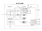
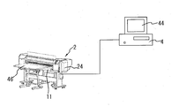
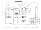
- FIG. 1 and 3 are schematic views of a light guide plate printing apparatus including an inkjet printer 2 and a computer 4 such as a personal computer connected to the controller of the printer 2 via an input / output interface.
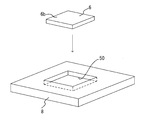
- the light guide plate 6 is held by the media driving mechanism 58 while being held in the fitting recess 50 of the board-shaped conveyance auxiliary member 8 with the printed surface 6b on the back side facing the light emitting surface 6a.
- it is conveyed on the platen 10 from the conveyance table 48 side.
- a printing unit 50 equipped with an inkjet recording head moves in a main scanning direction perpendicular to the conveying direction with respect to the light guide plate 6 on the platen 10 while ejecting ink from the nozzles.
- the print data transferred to the controller is printed on the printing surface 6b of the light guide plate 6 under the control of software stored in the controller. After the printing, the light guide plate 6 is transported onto a transport table 46 disposed on the guide 11.
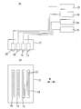
- a horizontal rail 52 is installed on the platen 10, and the carriage 12 is movably connected to the horizontal rail 52.
- the carriage 12 holds a plurality of ink jet recording heads 14, 16, 18, and 20.
- Each recording head 14, 16, 18, 20 includes a large number of nozzles 22 that eject ink.
- each of the heads 14, 16, 18, and 20 includes a white ink supply unit 56 that includes ink tanks 26, 28, 30, and 32 disposed in the machine body 24 of the printer 2, respectively.
- Each ink tank communicates with ink supply means such as a tube.
- the plurality of recording heads 14, 16, 18, and 20 are arranged in parallel so that their print areas overlap in the main scanning direction M along the horizontal rail 52 as shown in FIG.
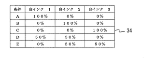
- the storage device of the computer 4 stores software (print program) for creating print data of the light reflection pattern, and is provided with a data table 34 shown in FIG.
- This data table 34 is a combination of color temperature and ink so that a plurality of types of white ink can be printed on the light guide plate individually or in combination to create light guide plates of various color temperatures. Are set in advance, and by using the data table 34, light guide plates having various color temperatures can be easily created.
- the software for printing control stored in the computer can create and modify the data table 34. As shown in FIG.
- the created light guide plate 6 is obtained by printing reflective dots or reflective gradients (fine dots such as frosted glass) on the plane portion of the printing surface 6 b of the transparent acrylic plate.
- a light source 54 made of a light emitter such as a cold cathode tube or an LED in the thickness portion of the light guide plate 6, the entire light emitting surface 6a appears to emit light.
- the data table 34 shows an example when three types of white inks 1, 2, and 3 having different color temperatures are prepared.
- ink using titanium oxide prepare white ink with different color temperature depending on the particle size distribution of titanium oxide in the ink, and changing the particle size distribution variation will cause a difference in reflected light.
- color temperature There is a difference in color temperature. This is because the particle diameter of titanium oxide in the ink is different, so that the intensity of light scattered after printing varies depending on the wavelength of the light, and as a result, the color temperature of the scattered light of the printed light guide plate varies.
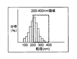
- White ink uses titanium oxide as an ink pigment. Titanium oxide particles have the property of reflecting the light with the wavelength twice as large as the particle diameter.
- the ideal white ink has a uniform titanium oxide particle size distribution of 200 nm to 400 nm as shown in FIG. Is to exist. In this case, the color becomes white which uniformly reflects light 400 nm to 800 nm (visible light) having a wavelength twice as large as the particle diameter 200 nm to 400 nm.
- the particle size distribution rarely exists uniformly at 200 nm-400 nm, (1) When there are many particles having a particle diameter of 200 nm (see FIG.
- white ink that strongly reflects 400 nm light (short wavelength) When there are many particles having a particle diameter of 400 nm (see FIG. 13), white ink that strongly reflects light (long wavelength) at 800 nm, white ink with a low color temperature, red, yellow, or green is obtained.
- a desired light wavelength region may be obtained by adding other particles, copper phthalocyanine, or the like.
- a plurality of types of white ink having different titanium oxide distributions are prepared and used in combination.
- the printer includes only one type of white ink, and the distribution state of titanium oxide in the ink is adjusted in advance to a desired distribution state, and printing is performed on the light guide plate using the adjusted white ink. good.
- the printer has only one type of white ink, and the distribution state of titanium oxide in the ink is adjusted in advance to a desired distribution state, and printing is performed on the light guide plate using the adjusted white ink. May be prepared, and different types of white ink may be used for each printer, and one of them may be designated as necessary to create a light guide plate having a desired color temperature.
- FIGS. 11 to 13 are distribution image diagrams of the particle diameter of titanium oxide in the ink.
- the horizontal axis indicates the particle diameter, and the vertical axis indicates the degree of distribution.
- FIG. 11 shows an ideal distribution of titanium oxide particles in white ink
- FIGS. 12 to 13 show an actual distribution of titanium oxide particles in white ink.
- FIG. 2 when the light source is the same, and the color temperature of the light guide plate is 4500K when printing is performed under the printing condition A shown in FIG. 2, when printing is performed under the condition B, printing is performed under the conditions of 5000K and C. When combined, a color temperature between 4500K and 5000K can be obtained under the condition D, and between 5000K and 5500K under the condition E.
- FIG. 1 when the light source is the same, and the color temperature of the light guide plate is 4500K when printing is performed under the printing condition A shown in FIG. 2, when printing is performed under the condition B, printing is performed under the conditions of 5000K and C.
- the area of the light reflection pattern increases with distance from the light source.
- the pattern may be printed by increasing the density of the same area, or may be combined as necessary. Further, a pattern such as a gradation by fine printing that can be printed by an inkjet head may be used.
- 6 and 7 are explanatory diagrams of the printing operation of the ink jet recording head.
- the recording head 14 communicates with the ink tank 26 containing the white ink 1 described in the data table 34, and the recording head 16 has the white ink.
- the recording head 18 communicates with an ink tank 30 containing white ink 3.
- the white inks 1, 2 and 3 have different particle size distributions of titanium oxide in the ink, thereby making the ink color temperatures different.
- 6A and 6B show the printing operation for condition B shown in the data table 34 of FIG.
- a normal amount of white ink 2 ink dots 36 are ejected from the nozzles of the recording head 16, and one 100% white ink 2 ink dot 36 is formed on the light guide plate 6. Shows the state. That is, the entire surface is printed using only the white ink 2.
- FIG. 7A, 7B, and 7C show the printing operation under the printing condition E shown in the data table 34 of FIG.
- the ink dots 38 of the normal amount of the white ink 2 are ejected from the nozzles of the recording head 16 and printed on the light guide plate 6.
- half of the normal amount of white ink 3 ink dots 38 are ejected from the recording head 18 onto the ink dots 38 of the white ink 2 that has been printed first, and the two ink dots 38, 38 overlap.
- One dot is printed.
- the white ink 2 is 50% and the white ink 3 is 50%. That is, the entire surface is printed by combining the white ink 2 and the white ink 3.
- This ink ejection control is performed by preparing a plurality of printing waveforms and driving voltages for driving the head, and selecting and using the necessary driving waveforms and driving voltages.
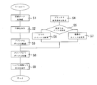
- step 1 the operator creates reflective surface print data 42 on the computer 4 using software for creating a reflection pattern of the light guide plate.
- the print data 42 is displayed on the display 44 of the computer 4.
- the display 44 displays a data input display 48 indicating the use conditions A, B, C, D, E, and F of white ink.
- the use conditions A, B, C, D, E, and F of the display 48 correspond to the data table 34.
- the operator refers to the display 48 on the display 44 of the computer 4 in step 2 to select a use condition, and clicks the condition selection button display 46 using an input means such as a mouse, and sends the use condition to the computer 4. That is, the printing conditions are input.
- the computer refers to the data table 34 according to the selected condition, and determines the ink 1, 2, 3 to be used in step 3.
- the computer 4 selects a mode in which one white ink is used in step 4 or a mode in which a plurality of white inks are used in step 5.
- the print button 50 is executed from the screen of the computer 4 in step 6, the print data is transferred from the computer 4 to the printer 2 (step 7), and after the data is processed in the printer 2 (step 8), the recording head Is driven in the main scanning direction, and printing is performed with the white ink under the printing conditions selected on the light guide plate 6 (step 9).
- the technique has been described in which white ink having a different color temperature is printed at the same position at 50%.
- the data table 34 may be provided in a memory mounted on the controller of the printer 2. In this case, the printing conditions are first set on the printer 2 side, and only the print data is transferred from the computer 4. Just do it.
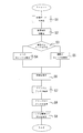
- FIG. 13 shows a configuration in which the data table 34 is provided in a memory mounted on the controller of the printer 2. The operation in this case will be described below with reference to the flowchart shown in FIG.
- step 1 the operator creates reflective surface print data 42 on the computer 4 using software for creating a reflection pattern of the light guide plate.
- the print data 42 is displayed on the display 44 of the computer 4.
- a display for data input indicating the use conditions A, B, C, D, E, and F of the white ink is displayed on the display of the controller of the printer 2.
- the display usage conditions A, B, C, D, E, and F correspond to the data table 34.
- step 4 the operator refers to the display on the controller display, selects a use condition, and sets the use condition, that is, the print condition, in the controller of the printer 2 using an input unit such as a keyboard.
- the controller refers to the data table 34 according to the selected condition, and determines the inks 1, 2, and 3 to be used in step 5.
- the controller selects a mode in which one white ink is used in step 6 or a mode in which a plurality of white inks are used in step 7.
- the print data is transferred from the computer 4 to the printer 2 (step 3), and after the data is processed in the printer 2 (step 8). Then, the recording head is driven and printing is performed on the light guide plate 6 with the white ink under the selected printing conditions (step 9).
- the structure is described in which the recording heads are arranged in parallel in the serial printer in which the recording heads move in the main scanning direction.
- a line head longer than the width of the optical plate may be used to arrange the light guide plate in a direction perpendicular to the conveyance direction.
- the printer may use a structure in which the light guide plate is fixed on the platen and the recording head moves.
- Inkjet printer 4 Computer 6 Light guide plate 8 Transport auxiliary member 10 Platen 12 Carriage 14 Recording head 16 Recording head 18 Recording head 20 Recording head 22 Nozzle 24 Machine body 26 Ink tank 28 Ink tank 30 Ink tank 32 Ink tank 34 Data table 36 Ink dots 38 Ink dots 40 Ink dots 42 Print data 44 Display 46 Transport table 48 Transport table 50 Print section 52 Horizontal rail 54 Light source 56 White ink supply section 58 Media drive mechanism
Landscapes
- Physics & Mathematics (AREA)
- General Physics & Mathematics (AREA)
- Optics & Photonics (AREA)
- Manufacturing & Machinery (AREA)
- Engineering & Computer Science (AREA)
- Nonlinear Science (AREA)
- Mathematical Physics (AREA)
- Crystallography & Structural Chemistry (AREA)
- Chemical & Material Sciences (AREA)
- Planar Illumination Modules (AREA)
- Ink Jet (AREA)
- Ink Jet Recording Methods And Recording Media Thereof (AREA)
- Light Guides In General And Applications Therefor (AREA)
- Optical Elements Other Than Lenses (AREA)
- Inks, Pencil-Leads, Or Crayons (AREA)
Priority Applications (2)
| Application Number | Priority Date | Filing Date | Title |
|---|---|---|---|
| US14/009,973 US20140023780A1 (en) | 2011-04-08 | 2012-02-13 | Method and device for creating light guide plate |
| EP12767247.5A EP2696130A4 (en) | 2011-04-08 | 2012-02-13 | METHOD AND DEVICE FOR GENERATING A LIGHT CONDUCTOR PLATE |
Applications Claiming Priority (2)
| Application Number | Priority Date | Filing Date | Title |
|---|---|---|---|
| JP2011-085859 | 2011-04-08 | ||
| JP2011085859A JP5514141B2 (ja) | 2011-04-08 | 2011-04-08 | 導光板作成方法及び装置 |
Publications (1)
| Publication Number | Publication Date |
|---|---|
| WO2012137537A1 true WO2012137537A1 (ja) | 2012-10-11 |
Family
ID=46968941
Family Applications (1)
| Application Number | Title | Priority Date | Filing Date |
|---|---|---|---|
| PCT/JP2012/053226 Ceased WO2012137537A1 (ja) | 2011-04-08 | 2012-02-13 | 導光板作成方法及び装置 |
Country Status (7)
| Country | Link |
|---|---|
| US (1) | US20140023780A1 (enExample) |
| EP (1) | EP2696130A4 (enExample) |
| JP (1) | JP5514141B2 (enExample) |
| KR (1) | KR101266314B1 (enExample) |
| CN (1) | CN102729677B (enExample) |
| TW (1) | TWI446033B (enExample) |
| WO (1) | WO2012137537A1 (enExample) |
Families Citing this family (6)
| Publication number | Priority date | Publication date | Assignee | Title |
|---|---|---|---|---|
| JP5462306B2 (ja) * | 2012-03-28 | 2014-04-02 | 武藤工業株式会社 | 導光板作成方法 |
| JP2014203671A (ja) * | 2013-04-04 | 2014-10-27 | 株式会社ミマキエンジニアリング | バックライト導光板、バックライト導光板製造方法及びインクジェットプリンタ |
| CN105363626A (zh) * | 2015-08-31 | 2016-03-02 | 陈青苹 | 一种导光板网点点胶机 |
| CN106066507A (zh) * | 2016-07-29 | 2016-11-02 | 马剑星 | 一种补强表面光学结构的导光板及其工艺方法 |
| KR102038609B1 (ko) * | 2017-08-17 | 2019-10-31 | (재)한국건설생활환경시험연구원 | 복수의 도트로 이루어진 패턴을 구비하는 도광판 |
| CN115027160A (zh) * | 2022-07-05 | 2022-09-09 | 冠捷显示科技(厦门)有限公司 | 一种带反射功能支撑钉组件的制造方法 |
Citations (3)
| Publication number | Priority date | Publication date | Assignee | Title |
|---|---|---|---|---|
| JPH0968614A (ja) | 1995-08-31 | 1997-03-11 | Rohm Co Ltd | 面照明装置および面照明装置用導光板の製造方法 |
| JP2010165548A (ja) * | 2009-01-15 | 2010-07-29 | Kuraray Co Ltd | 導光板及び導光板の製造方法 |
| JP2010205417A (ja) * | 2009-02-27 | 2010-09-16 | Nec Lcd Technologies Ltd | 面発光装置 |
Family Cites Families (4)
| Publication number | Priority date | Publication date | Assignee | Title |
|---|---|---|---|---|
| JP3471573B2 (ja) * | 1997-07-18 | 2003-12-02 | 株式会社リコー | インクジェットヘッドの取付け構造体の製造方法および製造装置 |
| JP2001158099A (ja) * | 1999-12-02 | 2001-06-12 | Fuji Xerox Co Ltd | インクジェット記録ヘッド及びインクジェット記録装置 |
| CN101363934B (zh) * | 2007-08-10 | 2011-08-31 | 北京京东方光电科技有限公司 | 导光板加工方法和加工设备 |
| JP2010232090A (ja) | 2009-03-27 | 2010-10-14 | Fujikura Ltd | シートスイッチモジュール |
-
2011
- 2011-04-08 JP JP2011085859A patent/JP5514141B2/ja active Active
-
2012
- 2012-02-13 WO PCT/JP2012/053226 patent/WO2012137537A1/ja not_active Ceased
- 2012-02-13 US US14/009,973 patent/US20140023780A1/en not_active Abandoned
- 2012-02-13 EP EP12767247.5A patent/EP2696130A4/en not_active Withdrawn
- 2012-02-16 TW TW101105031A patent/TWI446033B/zh not_active IP Right Cessation
- 2012-03-13 KR KR1020120025313A patent/KR101266314B1/ko not_active Expired - Fee Related
- 2012-03-29 CN CN201210087455.2A patent/CN102729677B/zh not_active Expired - Fee Related
Patent Citations (3)
| Publication number | Priority date | Publication date | Assignee | Title |
|---|---|---|---|---|
| JPH0968614A (ja) | 1995-08-31 | 1997-03-11 | Rohm Co Ltd | 面照明装置および面照明装置用導光板の製造方法 |
| JP2010165548A (ja) * | 2009-01-15 | 2010-07-29 | Kuraray Co Ltd | 導光板及び導光板の製造方法 |
| JP2010205417A (ja) * | 2009-02-27 | 2010-09-16 | Nec Lcd Technologies Ltd | 面発光装置 |
Non-Patent Citations (1)
| Title |
|---|
| See also references of EP2696130A4 * |
Also Published As
| Publication number | Publication date |
|---|---|
| CN102729677A (zh) | 2012-10-17 |
| KR20120115095A (ko) | 2012-10-17 |
| JP2012220694A (ja) | 2012-11-12 |
| US20140023780A1 (en) | 2014-01-23 |
| EP2696130A4 (en) | 2014-08-27 |
| JP5514141B2 (ja) | 2014-06-04 |
| TWI446033B (zh) | 2014-07-21 |
| CN102729677B (zh) | 2014-10-01 |
| TW201243407A (en) | 2012-11-01 |
| KR101266314B1 (ko) | 2013-05-22 |
| EP2696130A1 (en) | 2014-02-12 |
Similar Documents
| Publication | Publication Date | Title |
|---|---|---|
| JP5514141B2 (ja) | 導光板作成方法及び装置 | |
| US8888270B2 (en) | Inkjet recording apparatus and image forming method | |
| JP6043134B2 (ja) | 面発光照明装置の色温度の調整方法 | |
| JP2012220694A5 (enExample) | ||
| JP6043135B2 (ja) | 導光板作成方法及び装置及び導光板 | |
| JP5462306B2 (ja) | 導光板作成方法 | |
| TWI490567B (zh) | Light guide plate making method and device | |
| US20220379546A1 (en) | Shaping apparatus and shaping method | |
| TWI479208B (zh) | Method and device for making light guide plate for LCD TV | |
| TWI490566B (zh) | Light guide plate making method and device | |
| JP2014022223A (ja) | 両面に発光面を有する面発光用装置及び該装置に用いられる導光板を製造する方法 | |
| JP2014063581A5 (ja) | 導光板作成方法及び装置及び導光板 |
Legal Events
| Date | Code | Title | Description |
|---|---|---|---|
| 121 | Ep: the epo has been informed by wipo that ep was designated in this application |
Ref document number: 12767247 Country of ref document: EP Kind code of ref document: A1 |
|
| WWE | Wipo information: entry into national phase |
Ref document number: 2012767247 Country of ref document: EP |
|
| WWE | Wipo information: entry into national phase |
Ref document number: 14009973 Country of ref document: US |
|
| NENP | Non-entry into the national phase |
Ref country code: DE |