WO2012137356A1 - 風力発電装置の制御装置、風力発電装置、ウインドファーム、及び風力発電装置の制御方法 - Google Patents
風力発電装置の制御装置、風力発電装置、ウインドファーム、及び風力発電装置の制御方法 Download PDFInfo
- Publication number
- WO2012137356A1 WO2012137356A1 PCT/JP2011/060552 JP2011060552W WO2012137356A1 WO 2012137356 A1 WO2012137356 A1 WO 2012137356A1 JP 2011060552 W JP2011060552 W JP 2011060552W WO 2012137356 A1 WO2012137356 A1 WO 2012137356A1
- Authority
- WO
- WIPO (PCT)
- Prior art keywords
- current
- power
- output
- wind
- power system
- Prior art date
Links
- 238000000034 method Methods 0.000 title claims description 17
- 238000010248 power generation Methods 0.000 title abstract description 34
- 238000001514 detection method Methods 0.000 claims abstract description 28
- 238000011084 recovery Methods 0.000 description 11
- 230000005856 abnormality Effects 0.000 description 9
- 230000007423 decrease Effects 0.000 description 9
- 239000002131 composite material Substances 0.000 description 7
- 238000010586 diagram Methods 0.000 description 6
- 230000003247 decreasing effect Effects 0.000 description 4
- 230000000694 effects Effects 0.000 description 1
- 238000009434 installation Methods 0.000 description 1
Images


Classifications
-
- F—MECHANICAL ENGINEERING; LIGHTING; HEATING; WEAPONS; BLASTING
- F03—MACHINES OR ENGINES FOR LIQUIDS; WIND, SPRING, OR WEIGHT MOTORS; PRODUCING MECHANICAL POWER OR A REACTIVE PROPULSIVE THRUST, NOT OTHERWISE PROVIDED FOR
- F03D—WIND MOTORS
- F03D7/00—Controlling wind motors
- F03D7/02—Controlling wind motors the wind motors having rotation axis substantially parallel to the air flow entering the rotor
- F03D7/028—Controlling wind motors the wind motors having rotation axis substantially parallel to the air flow entering the rotor controlling wind motor output power
- F03D7/0284—Controlling wind motors the wind motors having rotation axis substantially parallel to the air flow entering the rotor controlling wind motor output power in relation to the state of the electric grid
-
- F—MECHANICAL ENGINEERING; LIGHTING; HEATING; WEAPONS; BLASTING
- F03—MACHINES OR ENGINES FOR LIQUIDS; WIND, SPRING, OR WEIGHT MOTORS; PRODUCING MECHANICAL POWER OR A REACTIVE PROPULSIVE THRUST, NOT OTHERWISE PROVIDED FOR
- F03D—WIND MOTORS
- F03D7/00—Controlling wind motors
- F03D7/02—Controlling wind motors the wind motors having rotation axis substantially parallel to the air flow entering the rotor
- F03D7/04—Automatic control; Regulation
- F03D7/042—Automatic control; Regulation by means of an electrical or electronic controller
- F03D7/048—Automatic control; Regulation by means of an electrical or electronic controller controlling wind farms
-
- F—MECHANICAL ENGINEERING; LIGHTING; HEATING; WEAPONS; BLASTING
- F03—MACHINES OR ENGINES FOR LIQUIDS; WIND, SPRING, OR WEIGHT MOTORS; PRODUCING MECHANICAL POWER OR A REACTIVE PROPULSIVE THRUST, NOT OTHERWISE PROVIDED FOR
- F03D—WIND MOTORS
- F03D9/00—Adaptations of wind motors for special use; Combinations of wind motors with apparatus driven thereby; Wind motors specially adapted for installation in particular locations
- F03D9/20—Wind motors characterised by the driven apparatus
- F03D9/25—Wind motors characterised by the driven apparatus the apparatus being an electrical generator
- F03D9/255—Wind motors characterised by the driven apparatus the apparatus being an electrical generator connected to electrical distribution networks; Arrangements therefor
- F03D9/257—Wind motors characterised by the driven apparatus the apparatus being an electrical generator connected to electrical distribution networks; Arrangements therefor the wind motor being part of a wind farm
-
- H—ELECTRICITY
- H02—GENERATION; CONVERSION OR DISTRIBUTION OF ELECTRIC POWER
- H02J—CIRCUIT ARRANGEMENTS OR SYSTEMS FOR SUPPLYING OR DISTRIBUTING ELECTRIC POWER; SYSTEMS FOR STORING ELECTRIC ENERGY
- H02J3/00—Circuit arrangements for ac mains or ac distribution networks
- H02J3/38—Arrangements for parallely feeding a single network by two or more generators, converters or transformers
- H02J3/381—Dispersed generators
-
- H—ELECTRICITY
- H02—GENERATION; CONVERSION OR DISTRIBUTION OF ELECTRIC POWER
- H02J—CIRCUIT ARRANGEMENTS OR SYSTEMS FOR SUPPLYING OR DISTRIBUTING ELECTRIC POWER; SYSTEMS FOR STORING ELECTRIC ENERGY
- H02J3/00—Circuit arrangements for ac mains or ac distribution networks
- H02J3/38—Arrangements for parallely feeding a single network by two or more generators, converters or transformers
- H02J3/46—Controlling of the sharing of output between the generators, converters, or transformers
- H02J3/50—Controlling the sharing of the out-of-phase component
-
- F—MECHANICAL ENGINEERING; LIGHTING; HEATING; WEAPONS; BLASTING
- F05—INDEXING SCHEMES RELATING TO ENGINES OR PUMPS IN VARIOUS SUBCLASSES OF CLASSES F01-F04
- F05B—INDEXING SCHEME RELATING TO WIND, SPRING, WEIGHT, INERTIA OR LIKE MOTORS, TO MACHINES OR ENGINES FOR LIQUIDS COVERED BY SUBCLASSES F03B, F03D AND F03G
- F05B2270/00—Control
- F05B2270/30—Control parameters, e.g. input parameters
- F05B2270/337—Electrical grid status parameters, e.g. voltage, frequency or power demand
-
- H—ELECTRICITY
- H02—GENERATION; CONVERSION OR DISTRIBUTION OF ELECTRIC POWER
- H02J—CIRCUIT ARRANGEMENTS OR SYSTEMS FOR SUPPLYING OR DISTRIBUTING ELECTRIC POWER; SYSTEMS FOR STORING ELECTRIC ENERGY
- H02J2203/00—Indexing scheme relating to details of circuit arrangements for AC mains or AC distribution networks
- H02J2203/20—Simulating, e g planning, reliability check, modelling or computer assisted design [CAD]
-
- H—ELECTRICITY
- H02—GENERATION; CONVERSION OR DISTRIBUTION OF ELECTRIC POWER
- H02J—CIRCUIT ARRANGEMENTS OR SYSTEMS FOR SUPPLYING OR DISTRIBUTING ELECTRIC POWER; SYSTEMS FOR STORING ELECTRIC ENERGY
- H02J2300/00—Systems for supplying or distributing electric power characterised by decentralized, dispersed, or local generation
- H02J2300/20—The dispersed energy generation being of renewable origin
- H02J2300/28—The renewable source being wind energy
-
- Y—GENERAL TAGGING OF NEW TECHNOLOGICAL DEVELOPMENTS; GENERAL TAGGING OF CROSS-SECTIONAL TECHNOLOGIES SPANNING OVER SEVERAL SECTIONS OF THE IPC; TECHNICAL SUBJECTS COVERED BY FORMER USPC CROSS-REFERENCE ART COLLECTIONS [XRACs] AND DIGESTS
- Y02—TECHNOLOGIES OR APPLICATIONS FOR MITIGATION OR ADAPTATION AGAINST CLIMATE CHANGE
- Y02E—REDUCTION OF GREENHOUSE GAS [GHG] EMISSIONS, RELATED TO ENERGY GENERATION, TRANSMISSION OR DISTRIBUTION
- Y02E10/00—Energy generation through renewable energy sources
- Y02E10/70—Wind energy
- Y02E10/72—Wind turbines with rotation axis in wind direction
-
- Y—GENERAL TAGGING OF NEW TECHNOLOGICAL DEVELOPMENTS; GENERAL TAGGING OF CROSS-SECTIONAL TECHNOLOGIES SPANNING OVER SEVERAL SECTIONS OF THE IPC; TECHNICAL SUBJECTS COVERED BY FORMER USPC CROSS-REFERENCE ART COLLECTIONS [XRACs] AND DIGESTS
- Y02—TECHNOLOGIES OR APPLICATIONS FOR MITIGATION OR ADAPTATION AGAINST CLIMATE CHANGE
- Y02E—REDUCTION OF GREENHOUSE GAS [GHG] EMISSIONS, RELATED TO ENERGY GENERATION, TRANSMISSION OR DISTRIBUTION
- Y02E10/00—Energy generation through renewable energy sources
- Y02E10/70—Wind energy
- Y02E10/76—Power conversion electric or electronic aspects
-
- Y—GENERAL TAGGING OF NEW TECHNOLOGICAL DEVELOPMENTS; GENERAL TAGGING OF CROSS-SECTIONAL TECHNOLOGIES SPANNING OVER SEVERAL SECTIONS OF THE IPC; TECHNICAL SUBJECTS COVERED BY FORMER USPC CROSS-REFERENCE ART COLLECTIONS [XRACs] AND DIGESTS
- Y02—TECHNOLOGIES OR APPLICATIONS FOR MITIGATION OR ADAPTATION AGAINST CLIMATE CHANGE
- Y02E—REDUCTION OF GREENHOUSE GAS [GHG] EMISSIONS, RELATED TO ENERGY GENERATION, TRANSMISSION OR DISTRIBUTION
- Y02E60/00—Enabling technologies; Technologies with a potential or indirect contribution to GHG emissions mitigation
-
- Y—GENERAL TAGGING OF NEW TECHNOLOGICAL DEVELOPMENTS; GENERAL TAGGING OF CROSS-SECTIONAL TECHNOLOGIES SPANNING OVER SEVERAL SECTIONS OF THE IPC; TECHNICAL SUBJECTS COVERED BY FORMER USPC CROSS-REFERENCE ART COLLECTIONS [XRACs] AND DIGESTS
- Y04—INFORMATION OR COMMUNICATION TECHNOLOGIES HAVING AN IMPACT ON OTHER TECHNOLOGY AREAS
- Y04S—SYSTEMS INTEGRATING TECHNOLOGIES RELATED TO POWER NETWORK OPERATION, COMMUNICATION OR INFORMATION TECHNOLOGIES FOR IMPROVING THE ELECTRICAL POWER GENERATION, TRANSMISSION, DISTRIBUTION, MANAGEMENT OR USAGE, i.e. SMART GRIDS
- Y04S40/00—Systems for electrical power generation, transmission, distribution or end-user application management characterised by the use of communication or information technologies, or communication or information technology specific aspects supporting them
- Y04S40/20—Information technology specific aspects, e.g. CAD, simulation, modelling, system security
Definitions
- the present invention relates to a wind turbine generator control device, a wind turbine generator, a wind farm, and a wind turbine generator control method.
- the wind farm has a plurality of wind power generators, and supplies the power generated by the wind power generators to the power system.
- the wind farm provides voltage support that recovers the reduced voltage by supplying reactive current, and effective
- the power system is stabilized by performing frequency support that recovers the frequency that has decreased by supplying current (Primary Frequency Control).
- Patent Document 1 describes that when the frequency of the power system is lowered, the output of the wind power generator is further supplied to the power system.
- the present invention has been made in view of such circumstances, and is a wind turbine generator control device, a wind turbine generator, a wind farm, and a wind turbine generator capable of quickly recovering a reduced voltage of a power system. It is an object to provide a control method.
- the wind power generator control device employs the following means.
- the control device for a wind power generator is a control device for a wind power generator that generates electric power by rotating a rotor and supplies the generated electric power to an electric power system.
- a detection means for detecting at least one of the frequency, and when a change that satisfies a predetermined condition with respect to a reference value occurs in a value detected by the detection means, the active current and the reactive current are determined.
- Output current control means for controlling the wind power generator so as to output a reactive current corresponding to a required output current indicating an output amount to the power system based on a detection result by the detection means, to the power system; Prepare.
- the voltage or frequency of the power system is detected by the detecting means.
- the power system is supplied with electric power from a wind power generator that generates electric power by rotating the rotor.
- the output current control means controls the wind turbine generator so that a required output current that is determined by the active current and the reactive current and indicates the output amount to the power system based on the detection result by the detection means is output to the power system. .
- the active current contributes to an increase in the frequency of the power grid
- the reactive current contributes to an increase in the voltage of the power grid.
- the output current control means outputs a reactive current corresponding to the required output current to the power system when the value detected by the detection means changes so as to satisfy a predetermined condition with respect to the reference value. To control the wind power generator.
- the case where the value detected by the detecting means changes in a condition that satisfies a predetermined condition with respect to the reference value is a case where an abnormality such as an accident occurs in the power system such as disconnection of a large power plant. That is, when an abnormality occurs in the power system, the output current control means outputs a reactive current corresponding to the required output current from the wind power generator to the power system regardless of the effective current of the required output current. Therefore, the control device according to the first aspect of the present invention can quickly recover the voltage that has decreased in the power system.
- control device configured so that the output current control means has the required output current when the required output current exceeds the range of effective current and reactive current that can be output by the wind turbine generator.
- the wind power generator may be controlled so that a reactive current corresponding to the reactive current is output to the power system within the range.
- the required output current may be outside the range that can be output by the wind turbine generator.
- the wind turbine generator cannot output a current that satisfies the effective current and reactive current of the required output current to the power system. Therefore, when the required output current exceeds the range that can be output by the wind power generator, the control device of the first aspect generates a reactive current corresponding to the reactive current of the required output current within the range. Since the power is output from the apparatus to the power system, the voltage that has decreased in the power system can be quickly recovered.
- the output current control means recovers the voltage of the power system to a predetermined value
- the voltage and the frequency are recovered to the reference value. You may control the said wind power generator so that the effective current according to the said required output current may be output to the said electric power grid
- the frequency of the power system changes together with the voltage of the power system.
- effective current (energy) for recovering the frequency of the power system is not easily absorbed unless the voltage of the power system is large to some extent. Therefore, after the voltage of the power system is restored to a predetermined value, the output current control means supplies an effective current corresponding to the required output current to the power system until the voltage and the frequency are restored to the reference value.
- the wind turbine generator is controlled to output. Therefore, the control device according to the first aspect can quickly recover the reduced frequency of the power system.
- the wind turbine generator according to the second aspect of the present invention is a wind turbine generator that generates power by rotating the rotor and supplies the generated power to the power system, and includes the control device described above.
- control device described above since the control device described above is provided, it is possible to quickly recover the reduced voltage of the power system.
- the wind farm according to the third aspect of the present invention includes a plurality of the wind power generators described above, and the plurality of wind power generators are any of the output of the wind power generator, the wind speed, and the rotational speed of the rotor.
- the active current and reactive current output to the power system are divided into a plurality of different ratios.
- the plurality of wind turbine generators output an effective current to the power system according to any one of the output of the wind turbine generator, the wind speed, and the rotational speed of the rotor; It is divided into a plurality of groups having different ratios to the reactive current.
- size of the output of a wind power generator, a wind speed, and the rotation speed of a rotor includes the magnitude
- a plurality of wind turbine generators can be divided into a group that preferentially recovers voltage and a group that preferentially recovers frequency when an abnormality occurs in the power system.
- the voltage and frequency of the power system can be recovered.
- a wind farm according to a fourth aspect of the present invention includes a plurality of the wind power generators described above, and the plurality of wind power generators have a plurality of different ratios of effective current and reactive current output to the power system. Divided into groups.
- the plurality of wind turbine generators are divided in advance into a plurality of groups having different ratios of the effective current and the reactive current output to the power system, it is simple and efficient.
- the voltage and frequency of the power system can be recovered.
- a wind turbine generator control method is a wind turbine generator control method for generating electric power by rotating a rotor and supplying the generated electric power to an electric power system. And a first step for detecting at least one of the frequencies, and when a change that satisfies a predetermined condition with respect to a reference value occurs in a value detected in the first step, is determined by an active current and a reactive current. And a second step of controlling the wind turbine generator so as to output a reactive current corresponding to a required output current indicating an output amount to the power system based on a detection result of the first step to the power system; ,including.
- the output current control means causes the reactive current corresponding to the required output current to be output from the wind turbine generator to the power system regardless of the magnitude of the effective current of the required output current.
- the reduced voltage of the power system can be quickly recovered.
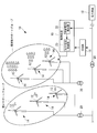
- FIG. 1 is a diagram showing an overall configuration of a wind farm 10 according to an embodiment of the present invention.
- the wind farm 10 includes a plurality of wind power generators 14 that generate power by the rotation of the rotor 12 and SCADA (Supervisory Control And Data Acquisition) 16 that is a control device that controls the operation state of each wind power generator 14.
- SCADA Supervisory Control And Data Acquisition
- the wind farm 10 will be described by taking as an example the case of including six wind power generators 14 as shown in FIG. 1, but the number of wind farms 10 is not particularly limited.
- wind power generator 14 is electrically connected to the other wind power generators 14 and the power system 18 via the transformer 20 and supplies the generated power to the power system 18.
- the wind power generators 14 each include a control device 19.
- the control apparatus 19 corresponding to only one wind power generator 14 is illustrated.
- the control device 19 controls the corresponding wind power generator 14 according to the control signal from the SCADA 16. Further, the control device 19 sets the wind power generator 14 so as to output to the power system 18 a current corresponding to the detection result of the system voltage detection unit 22 that detects the voltage and frequency of the power system 18 and the system voltage detection unit 22.
- An output current control unit 23 to be controlled is provided.
- the voltage of the power system 18 is referred to as a system voltage
- the frequency of the power system 18 is referred to as a system frequency.
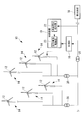
- system fault when an abnormality such as an accident (hereinafter referred to as “system fault”) occurs in the power system 18 such as disconnection of a large power plant, the system voltage and system frequency are set as a reference as shown in FIG. May vary from value.
- the reference value of the system voltage is 1 pu
- the reference value of the system frequency is 60 Hz.
- the control device 19 restores the power system to control the supply of power to the power system 18 by the wind power generator 14 so that the reduced system voltage and system frequency are restored to the reference values. Process.
- the active current contributes to an increase in the grid frequency, while the reactive current contributes to an increase in the grid voltage.
- the required output current is calculated by the output current control unit 23 based on the detection result by the system voltage detection unit 22 so that the system voltage and the system frequency become reference values. That is, when the system voltage decreases, the reactive current of the required output current becomes larger in order to recover the reduced system voltage, and accordingly, the output current control unit 23 disables the reactive current corresponding to the reactive current of the required output current.
- the current is output from the wind power generator 14 to the power system 18.
- the output current control unit 23 is effective according to the effective current of the required output current. The current is output from the wind power generator 14 to the power system 18.
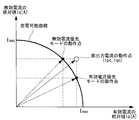
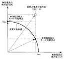
- FIG. 3 shows the range of effective current and reactive current that can be output by the wind power generator 14 as a power generation possible curve, with the horizontal axis representing the active current and the vertical axis representing the reactive current.
- a power generation possible curve is shown by (1) Formula.
- the example shown in FIG. 3 is a case where the required output current (Ipc, Iqc) is within the range of the power generation possible curve as shown in the equation (2).
- the control device 19 controls the wind power generator 14 so that the output current control unit 23 outputs the required output current.
- the output current control part 23 which concerns on this embodiment respond
- the wind power generator 14 is controlled to output the reactive current to the power system 18. That is, when a system fault occurs, the output current control unit 23 outputs a reactive current corresponding to the required output current from the wind power generator 14 to the power system 18 regardless of the magnitude of the effective current of the required output current.
- the required output current of the power system 18 may be outside the range of the power generation possible curve. In such a case, the wind turbine generator 14 cannot output a current that satisfies the effective current and reactive current of the required output current to the power system 18.
- the effective current Ipc of the required output current is less than the maximum value of the effective current that can be output by the wind turbine generator 14, and the reactive current Iqc of the required output current is the wind power.
- the reactive current that can be output by the power generation device 14 is equal to or less than the maximum value and the required output current of the power system 18 is outside the range of the power generation possible curve.
- the output current control unit 23 is in either the reactive current priority mode (voltage support control) for giving priority to the reactive current or the active current priority mode (frequency support control) for giving priority to the active current. One control is performed.
- the reactive current priority mode is voltage support control in which the system voltage is recovered with priority over the system frequency, and the wind turbine generator 14 generates a reactive current corresponding to the reactive current of the required output current within the range of the power generation possible curve. Output to system 18. Therefore, as shown by the operating point of the reactive current priority mode in FIG. 4, the reactive current has priority over the active current from the wind power generator 14 to the power system 18 regardless of the size of the effective current of the required output current. Is output.
- the active current priority mode is frequency support control that restores the system frequency with priority over the system voltage, and the wind turbine generator 14 generates an effective current corresponding to the effective current of the required output current within the range of the power generation possible curve. Is output to the power system 18. Therefore, as shown by the operating point of the active current priority mode in FIG. 4, the active current has priority over the reactive current from the wind power generator 14 to the power system 18 regardless of the magnitude of the reactive current of the required output current. Is output.
- the output current control unit 23 outputs a reactive current corresponding to the reactive current of the required output current when the required output current exceeds the range of the current that can be output by the wind turbine generator 14.
- the wind power generator 14 is controlled to output to the power system 18 within the range. That is, the output current control unit 23 preferentially recovers the system voltage by performing voltage support control in the reactive current priority mode.
- effective current (energy) for recovering the system frequency is less likely to be absorbed unless the system voltage is somewhat large.
- the wind power generator 14 outputs the reactive current on the power generation possible curve indicated by the operating point of the reactive current priority mode to the power system 18 by the voltage support control.
- the effective current Ipc of the required output current exceeds the effective current that can be output by the wind power generator 14, and the reactive current Iqc of the required output current is the wind power generator 14.
- the reactive current that can be output is equal to or less than the maximum value and the required output current of the power system 18 is outside the range of the power generation possible curve.
- the wind turbine generator 14 according to the present embodiment outputs the reactive current on the power generation possible curve indicated by the operating point of the reactive current priority mode to the power system 18 by the voltage support control.
- the effective current Ipc of the required output current is equal to or less than the effective current that can be output by the wind power generator 14, and the reactive current Iqc of the required output current is the wind power generator 14.
- the wind turbine generator 14 outputs the reactive current on the power generation possible curve indicated by the operating point of the reactive current priority mode to the power system 18 by the voltage support control.
- the reactive current output from the wind turbine generator 14 is the maximum value of the reactive current that can be output.
- the reactive current output from the wind turbine generator 14 is 0 (zero).
- the effective current Ipc of the required output current exceeds the effective current that can be output by the wind turbine generator 14 and the reactive current Iqc of the required output current is This is a case where the reactive current that can be output is exceeded and the required output current of the power system 18 is outside the range of the power generation possible curve. Also in this case, the wind turbine generator 14 according to the present embodiment outputs the reactive current on the power generation possible curve indicated by the operating point of the reactive current priority mode to the power system 18 by the voltage support control. However, since the reactive current Iqc of the required output current exceeds the reactive current that can be output by the wind turbine generator 14, the reactive current output from the wind turbine generator 14 is the maximum value of the reactive current that can be output. On the other hand, the reactive current output from the wind turbine generator 14 is 0 (zero).
- FIG. 8 is a flowchart showing the flow of processing of the power system recovery program executed by the control device 19 when the power system recovery processing according to the present embodiment is performed.
- the power system recovery program is provided in the control device 19. It is stored in advance in a predetermined area of a storage means (not shown).
- the power system recovery program according to the present embodiment is started when the value of the system voltage detected by the system voltage detection unit 22 changes so as to satisfy a condition predetermined with respect to the reference value.
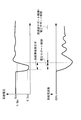
- the above condition is, for example, a case where a decrease in the system voltage of 0.2 pu or less continues for 150 msec as shown in FIG. That is, when the above conditions are satisfied, it is determined that an abnormality has occurred in the power system 18.
- a decrease in the system voltage that does not satisfy the above conditions is considered to be a temporary decrease in the system voltage that is not caused by a system fault, or a noise that occurs in the detection of the system voltage by the control device 19.
- control apparatus 19 will run an electric power system recovery program.
- step 100 voltage support control is performed, and the reactive current on the power generation possible curve is output to the power system 18 according to the reactive current in the reactive current priority mode.
- step 102 it is determined whether or not the system voltage has been restored to a predetermined value (for example, 0.9 pu, see also FIG. 2). Returns to step 100 and executes voltage support control until the system voltage reaches a predetermined value.
- a predetermined value for example, 0.9 pu, see also FIG. 2.
- step 104 composite support control, which is control combining voltage support control and frequency support control, is performed.
- a plurality of wind power generators 14 constituting the wind farm 10 have a plurality of different ratios of effective currents and reactive currents output to the power system 18.
- Divide into groups In the present embodiment, as an example, a frequency support group that controls a plurality of wind turbine generators 14 in the active current priority mode according to the output level of the wind turbine generators 14 when composite support control is performed, and Divide into voltage support groups controlled in reactive current priority mode.
- the average output of the whole wind farm 10 or a predetermined threshold value may be divided above and below, or N units in the order of high output.
- the wind power generators 14 may be frequency support groups and the other wind power generators 14 may be voltage support groups, or the M wind power generators 14 may be voltage support groups in order of lower output, and the other wind power generators 14 may be It may be a frequency support group. That is, since the higher output wind power generator 14 can output an effective current, such a wind power generator 14 is used as a frequency support group.
- the plurality of wind turbine generators 14 may be grouped according to the wind speed closely related to the output of the wind turbine generator 14 without being grouped according to the output level of the wind turbine generator 14.
- the wind power may be divided according to the average wind speed of the entire wind farm 10 or a predetermined threshold value, or N wind power generators in order of increasing wind speed.
- 14 may be a frequency support group, and the other wind turbine generators 14 may be voltage support groups, or M wind turbine generators 14 may be voltage support groups in order of increasing wind speed, and the other wind turbine generators 14 may be frequency support groups. Also good.
- the plurality of wind turbine generators 14 may be grouped by the number of rotations of the rotor 12 that is closely related to the output of the wind turbine generator 14.
- the wind power may be divided according to the average rotation speed of the entire wind farm 10 or a predetermined threshold value, or N wind turbines in descending order of rotation speed.
- the power generation device 14 may be a frequency support group and the other wind power generation devices 14 may be voltage support groups, or the M wind power generation devices 14 may be voltage support groups in order of decreasing rotation speed, and the other wind power generation devices 14 may be frequency. It may be a support group.
- the plurality of wind turbine generators 14 may be grouped based on the function size determined based on the output of the wind turbine generator, the wind speed, and the rotational speed of the rotor.
- step 106 it is determined whether or not the system voltage and the system frequency have been restored to the reference values. If the determination is affirmative, the program is terminated. If the determination is negative, the process returns to step 104 and the system voltage and The composite support control is executed until the system frequency returns to the reference value.
- the control device 19 is effective when the value of the system voltage detected by the system voltage detection unit 22 changes so as to satisfy a condition that is predetermined with respect to the reference value.
- the wind turbine generator is configured to output to the power system 18 a reactive current that is determined by the current and the reactive current and that corresponds to the required output current that indicates the output amount to the power system 18 based on the detection result by the system voltage detection unit 22 14 is controlled.
- the control device 19 outputs a reactive current corresponding to the required output current from the wind power generator 14 to the power system 18 regardless of the magnitude of the effective current of the required output current. Can be recovered.
- the control device 19 when the required output current exceeds the range of the current that can be output by the wind turbine generator 14, the control device 19 according to the present embodiment outputs the reactive current corresponding to the reactive current of the required output current within the range. Since it is made to output from a wind power generator 14 to an electric power grid, the lowered system voltage can be recovered quickly.
- control device 19 supplies an effective current corresponding to the required output current until the system voltage and the system frequency recover to the reference value after the system voltage recovers to a predetermined value. Since the wind power generator 14 is controlled so as to output to 18, the lowered system frequency can be quickly recovered.
- control device 19 when the control device 19 performs the power system recovery process when the system voltage detected by the system voltage detection unit 22 is reduced to satisfy a condition that is predetermined with respect to the reference value.
- the control device 19 includes a system frequency detection unit that detects a system frequency, and when the system frequency detected by the system frequency detection unit is reduced to satisfy a predetermined condition with respect to a reference value, The power system recovery process may be executed. In the case of this form, for example, when the decrease in the system frequency that is 80% or less of the reference value continues for 150 msec, the control device 19 executes the power system recovery process.
- control apparatus 19 performs an electric power system recovery
- the control device 19 performs the power system recovery process. Execute.
- the plurality of wind turbine generators 14 are effective currents that are output to the power system 18 according to the magnitude of the output of the wind turbine generators 14 when the composite support control is performed.
- the present invention is not limited to this, and the active current output by the plurality of wind turbine generators 14 to the power system 18 is not limited to this. It is good also as a form previously divided into the some group from which ratio with a reactive current differs.
- the wind power generator 14 having a large power generation rating may be a frequency support group, and the group having a low power generation rating may be a voltage support group.
- the wind power generator 14 that is in a deload operation which is an operation in which the output is limited in advance, is set as a frequency support group and is deloaded.
- Wind power generators 14 that are not connected may be included in the voltage support group.
- the wind power generators 14 may be grouped according to the installation location of the wind power generator 14.
- the said embodiment demonstrated the case where the some wind power generator 14 was divided into two groups, a frequency support group and a voltage support group, this invention is not limited to this, A plurality of wind power generation
- the device 14 may be divided into three or more groups.
- the reactive power supplied to the power system 18 is divided into a plurality of groups with different levels of reactive currents, and the output is large. Increase the contribution of frequency support as the group. Thereby, it can group into according to a more complicated wind condition.
- the said embodiment demonstrated the case where the some wind power generator 14 was divided into either a frequency support group and a voltage support group, this invention is not limited to this, A plurality of wind power generation A part of the device 14 may be divided into a frequency support group and a voltage support group, and the other part may not belong to either the frequency support group or the voltage support group. In the case of this form, the wind power generator 14 that does not belong to either the frequency support group or the voltage support group does not contribute to the power system recovery process.
- SCADA16 does at least any one of a system voltage or a system frequency. It is good also as a form which makes each of the some wind power generator 14 perform an electric power grid
Landscapes
- Engineering & Computer Science (AREA)
- Power Engineering (AREA)
- Life Sciences & Earth Sciences (AREA)
- Sustainable Development (AREA)
- Sustainable Energy (AREA)
- Chemical & Material Sciences (AREA)
- Combustion & Propulsion (AREA)
- Mechanical Engineering (AREA)
- General Engineering & Computer Science (AREA)
- Control Of Eletrric Generators (AREA)
- Wind Motors (AREA)
- Supply And Distribution Of Alternating Current (AREA)
Abstract
電力系統の低下した電圧を早急に回復させることを目的とする。制御装置(19)は、系統電圧検出部(22)によって検出された系統電圧の値に基準値に対して予め定められた条件を満たす変化が生じた場合に、有効電流と無効電流とによって定められると共に系統電圧検出部(22)による検出結果に基づいた電力系統(18)への出力量を示す要出力電流に応じた無効電流を、電力系統(18)へ出力するように風力発電装置(14)を制御する。
Description
本発明は、風力発電装置の制御装置、風力発電装置、ウインドファーム、及び風力発電装置の制御方法に関するものである。
ウインドファームは、複数の風力発電装置を有し、風力発電装置で発電した電力を電力系統へ供給する。そして、電力系統に事故が生じる等の異常によって、電力系統の電圧の低下や周波数の低下が生じた場合、ウインドファームは、無効電流を供給することで低下した電圧を回復させる電圧サポート、及び有効電流を供給(Primary Frequency Control)することで低下した周波数を回復させる周波数サポートを行うことによって、電力系統を安定化させている。
特許文献1には、電力系統の周波数が低下した場合に、風力発電装置の出力をさらに電力系統へ供給することが記載されている。
特許文献1には、電力系統の周波数が低下した場合に、風力発電装置の出力をさらに電力系統へ供給することが記載されている。
ところで、電力系統に異常が生じると、電力系統の電圧の低下と周波数の低下とが発生すると考えられる。そして、電力系統の電圧及び周波数が低下した場合、風力発電装置は、これらを回復させるための電力(電流)の供給を行う。特に、電力系統の低下した電圧が、早急に回復されなければならない。
本発明は、このような事情に鑑みてなされたものであって、電力系統の低下した電圧を早急に回復させることができる風力発電装置の制御装置、風力発電装置、ウインドファーム、及び風力発電装置の制御方法を提供することを目的とする。
上記課題を解決するために、本発明の風力発電装置の制御装置、風力発電装置、ウインドファーム、及び風力発電装置の制御方法は以下の手段を採用する。
すなわち、本発明の第1の態様に係る風力発電装置の制御装置は、ロータの回転により発電し、発電した電力を電力系統へ供給する風力発電装置の制御装置であって、前記電力系統の電圧及び周波数の少なくとも一方を検出する検出手段と、前記検出手段によって検出された値に基準値に対して予め定められた条件を満たす変化が生じた場合に、有効電流と無効電流とによって定められると共に前記検出手段による検出結果に基づいた前記電力系統への出力量を示す要出力電流に応じた無効電流を、前記電力系統へ出力するように前記風力発電装置を制御する出力電流制御手段と、を備える。
本発明の第1の態様によれば、検出手段によって、電力系統の電圧又は周波数が検出される。電力系統は、ロータの回転により発電する風力発電装置からの電力の供給を受ける。
出力電流制御手段は、有効電流と無効電流とによって定められると共に検出手段による検出結果に基づいた電力系統への出力量を示す要出力電流を、電力系統へ出力するように風力発電装置を制御する。
出力電流制御手段は、有効電流と無効電流とによって定められると共に検出手段による検出結果に基づいた電力系統への出力量を示す要出力電流を、電力系統へ出力するように風力発電装置を制御する。
なお、風力発電装置が電力系統へ出力する電流のうち、有効電流は電力系統の周波数の増加に寄与する一方、無効電流は電力系統の電圧の増加に寄与する。
そして、出力電流制御手段は、検出手段によって検出された値に基準値に対して予め定められた条件を満たす変化が生じた場合に、要出力電流に応じた無効電流を、電力系統へ出力するように風力発電装置を制御する。
そして、出力電流制御手段は、検出手段によって検出された値に基準値に対して予め定められた条件を満たす変化が生じた場合に、要出力電流に応じた無効電流を、電力系統へ出力するように風力発電装置を制御する。
検出手段によって検出された値に基準値に対して予め定められた条件を満たす変化が生じた場合とは、大型発電所の解列等、電力系統に事故等の異常が生じた場合である。すなわち、出力電流制御手段は、電力系統に異常が生じた場合、要出力電流の有効電流の大きさに係らず、要出力電流に応じた無効電流を風力発電装置から電力系統へ出力させる。
従って、本発明の第1の態様の制御装置は、電力系統の低下した電圧を早急に回復させることができる。
従って、本発明の第1の態様の制御装置は、電力系統の低下した電圧を早急に回復させることができる。
また、上記第1の態様の制御装置は、出力電流制御手段が、前記風力発電装置で出力可能な有効電流と無効電流との範囲を前記要出力電流が超えている場合に、該要出力電流の無効電流に応じた無効電流を該範囲内で前記電力系統へ出力するように前記風力発電装置を制御してもよい。
電力系統の電圧や周波数の低下量が大きいと、要出力電流が、風力発電装置で出力可能な範囲外となる場合がある。このような場合、風力発電装置は、要出力電流の有効電流と無効電流を満たす電流を電力系統へ出力することができない。
そこで、上記第1の態様の制御装置は、要出力電流が、風力発電装置で出力可能な範囲を超えている場合に、要出力電流の無効電流に応じた無効電流を該範囲内で風力発電装置から電力系統へ出力させるので、電力系統の低下した電圧を早急に回復させることができる。
そこで、上記第1の態様の制御装置は、要出力電流が、風力発電装置で出力可能な範囲を超えている場合に、要出力電流の無効電流に応じた無効電流を該範囲内で風力発電装置から電力系統へ出力させるので、電力系統の低下した電圧を早急に回復させることができる。
また、上記第1の態様の制御装置は、前記出力電流制御手段が、前記電力系統の電圧が予め定められた所定値に回復した後、該電圧及び該周波数が前記基準値に回復するまで、前記要出力電流に応じた有効電流を前記電力系統へ出力するように前記風力発電装置を制御してもよい。
電力系統に異常が生じると、電力系統の電圧と共に電力系統の周波数が変化すると考えられる。しかし、電力系統の電圧の大きさがある程度大きい状態でないと電力系統の周波数を回復させるための有効電流(エネルギー)は吸収されにくい。そこで、出力電流制御手段は、電力系統の電圧が予め定められた所定値に回復した後、該電圧及び該周波数が基準値に回復するまで、要出力電流に応じた有効電流を前記電力系統へ出力するように風力発電装置を制御する。
従って、上記第1の態様の制御装置は、電力系統の低下した周波数を早急に回復させることができる。
従って、上記第1の態様の制御装置は、電力系統の低下した周波数を早急に回復させることができる。
一方、本発明の第2の態様にかかる風力発電装置は、ロータの回転により発電し、発電した電力を電力系統へ供給する風力発電装置であって、上記記載の制御装置を備える。
本発明の第2の態様によれば、上記記載の制御装置を備えるので、電力系統の低下した電圧を早急に回復させることができる。
さらに、本発明の第3の態様に係るウインドファームは、上記記載の風力発電装置を複数備え、複数の前記風力発電装置が、前記風力発電装置の出力、風速、及び前記ロータの回転数の何れかの大きさに応じて、前記電力系統へ出力する有効電流と無効電流との比が異なる複数のグループに分けられる。
本発明の第3の態様によれば、複数の前記風力発電装置が、風力発電装置の出力、風速、及びロータの回転数の何れかの大きさに応じて、電力系統へ出力する有効電流と無効電流との比が異なる複数のグループに分けられる。なお、風力発電装置の出力、風速、及びロータの回転数の何れかの大きさとは、風力発電装置の出力、風速、及びロータの回転数を元に決定される関数の大きさを含む。
このため、複数の風力発電装置は、電力系統に異常が生じた場合に、電圧を優先的に回復させるグループと周波数を優先的に回復させるグループとに分けられることができるため、より効率的に電力系統の電圧及び周波数を回復させることができる。
また、本発明の第4の態様に係るウインドファームは、上記記載の風力発電装置を複数備え、複数の前記風力発電装置が、前記電力系統へ出力する有効電流と無効電流との比が異なる複数のグループに予め分けられる。
本発明の第4の態様によれば、複数の前記風力発電装置が、電力系統へ出力する有効電流と無効電流との比が異なる複数のグループに予め分けられているので、簡易かつ効率的に電力系統の電圧及び周波数を回復させることができる。
また、本発明の第5の態様に係る風力発電装置の制御方法は、ロータの回転により発電し、発電した電力を電力系統へ供給する風力発電装置の制御方法であって、前記電力系統の電圧及び周波数の少なくとも一方を検出する第1工程と、前記第1工程によって検出された値に基準値に対して予め定められた条件を満たす変化が生じた場合に、有効電流と無効電流とによって定められると共に前記第1工程による検出結果に基づいた前記電力系統への出力量を示す要出力電流に応じた無効電流を、前記電力系統へ出力するように前記風力発電装置を制御する第2工程と、を含む。
本発明の第5の態様によれば、出力電流制御手段は、要出力電流の有効電流の大きさに係らず、要出力電流に応じた無効電流を風力発電装置から電力系統へ出力させるので、電力系統の低下した電圧を早急に回復させることができる。
本発明によれば、電力系統の低下した電圧を早急に回復させることができる、という優れた効果を有する。
以下に、本発明に係る風力発電装置の制御装置、風力発電装置、ウインドファーム、及び風力発電装置の制御方法の一実施形態について、図面を参照して説明する。
図1は、本発明の実施形態に係るウインドファーム10の全体構成を示した図である。ウインドファーム10は、ロータ12の回転により発電する複数の風力発電装置14と、各風力発電装置14の運転状態を制御する制御装置であるSCADA(Supervisory Control And Data Acquisition)16とを備えている。本実施形態において、ウインドファーム10は、図1に示すように6台の風力発電装置14を備える場合を例に挙げて説明するが、台数は特に限定されない。
なお、風力発電装置14は、他の風力発電装置14及び電力系統18に変圧器20を介して電気的に接続され、発電した電力を電力系統18へ供給する。
風力発電装置14は、各々、制御装置19を備えている。なお、図1では、錯綜を回避するために、一の風力発電装置14にのみ対応する制御装置19を図示している。
制御装置19は、SCADA16からの制御信号に応じて、対応する風力発電装置14を制御する。また、制御装置19は、電力系統18の電圧及び周波数を検出する系統電圧検出部22、及び系統電圧検出部22の検出結果に応じた電流を電力系統18へ出力するように風力発電装置14を制御する出力電流制御部23を備えている。なお、以下の説明では、電力系統18の電圧を系統電圧と称呼し、電力系統18の周波数を系統周波数と称呼する。
ここで、例えば、大型発電所の解列等、電力系統18に事故(以下、「系統事故」という。)等の異常が生じることによって、図2に示すように、系統電圧及び系統周波数が基準値から変化する場合がある。なお、本実施形態では、一例として、系統電圧の基準値を1puとし、系統周波数の基準値を60Hzとする。
このような系統事故が発生した場合、制御装置19は、低下した系統電圧及び系統周波数が基準値に回復するように、風力発電装置14による電力系統18への電力の供給を制御する電力系統回復処理を行う。なお、風力発電装置14が電力系統18へ出力する電流のうち、有効電流は、系統周波数の増加に寄与する一方、無効電流は系統電圧の増加に寄与する。
このような系統事故が発生した場合、制御装置19は、低下した系統電圧及び系統周波数が基準値に回復するように、風力発電装置14による電力系統18への電力の供給を制御する電力系統回復処理を行う。なお、風力発電装置14が電力系統18へ出力する電流のうち、有効電流は、系統周波数の増加に寄与する一方、無効電流は系統電圧の増加に寄与する。
次に、有効電流Ipcと無効電流Iqcとによって定められると共に系統電圧検出部22による検出結果に基づいた電力系統18への出力量を示す要出力電流について説明する。
要出力電流は、出力電流制御部23によって、系統電圧検出部22による検出結果に基づいて、系統電圧及び系統周波数が基準値となるように算出される。
すなわち、系統電圧が低下した場合、低下した系統電圧を回復させるために要出力電流の無効電流はより大きくなり、これに伴い、出力電流制御部23は、要出力電流の無効電流に応じた無効電流を風力発電装置14から電力系統18へ出力させる。一方、系統周波数が低下した場合、低下した系統周波数を回復させるために要出力電流の有効電流はより大きくなり、これに伴い、出力電流制御部23は、要出力電流の有効電流に応じた有効電流を風力発電装置14から電力系統18へ出力させる。
すなわち、系統電圧が低下した場合、低下した系統電圧を回復させるために要出力電流の無効電流はより大きくなり、これに伴い、出力電流制御部23は、要出力電流の無効電流に応じた無効電流を風力発電装置14から電力系統18へ出力させる。一方、系統周波数が低下した場合、低下した系統周波数を回復させるために要出力電流の有効電流はより大きくなり、これに伴い、出力電流制御部23は、要出力電流の有効電流に応じた有効電流を風力発電装置14から電力系統18へ出力させる。
図3は、横軸を有効電流、縦軸を無効電流とし、風力発電装置14で出力可能な有効電流と無効電流との範囲を発電可能曲線として示している。なお、発電可能曲線は、(1)式で示される。

そして、図3に示す例は、(2)式に示すように、要出力電流(Ipc,Iqc)が発電可能曲線の範囲内にある場合である。

この場合、要出力電流が発電可能曲線の範囲内にあるため、制御装置19は、出力電流制御部23によって、該要出力電流を出力するように風力発電装置14を制御する。
そして、本実施形態に係る出力電流制御部23は、系統電圧検出部22によって検出された値に基準値に対して予め定められた条件を満たす変化が生じた場合に、要出力電流に応じた無効電流を、電力系統18へ出力するように風力発電装置14を制御する。すなわち、出力電流制御部23は、系統事故が生じた場合、要出力電流の有効電流の大きさに係らず、要出力電流に応じた無効電流を風力発電装置14から電力系統18へ出力させる。
しかしながら、図4~7に示すように、系統電圧や系統周波数の低下量が大きいと、電力系統18の要出力電流が発電可能曲線の範囲外となる場合がある。このような場合、風力発電装置14は、要出力電流の有効電流と無効電流を満たす電流を電力系統18へ出力することができない。
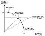
図4に示す例は、(3)式に示すように、要出力電流の有効電流Ipcが風力発電装置14で出力可能な有効電流の最大値以下であり、要出力電流の無効電流Iqcが風力発電装置14で出力可能な無効電流の最大値以下であり、かつ電力系統18の要出力電流が発電可能曲線の範囲外となる場合である。

このような場合、出力電流制御部23は、無効電流を優先して出力する無効電流優先モード(電圧サポート制御)又は有効電流を優先して出力する有効電流優先モード(周波数サポート制御)の何れか一方の制御を行う。
無効電流優先モードは、系統周波数よりも系統電圧を優先して回復させる電圧サポート制御であり、風力発電装置14は、要出力電流の無効電流に応じた無効電流を発電可能曲線の範囲内で電力系統18へ出力する。そのため、図4の無効電流優先モードの動作点で示されるように、要出力電流の有効電流の大きさにかかわらず、無効電流が有効電流よりも優先して風力発電装置14から電力系統18へ出力される。
一方、有効電流優先モードは、系統電圧よりも系統周波数を優先して回復させる周波数サポート制御であり、風力発電装置14は、要出力電流の有効電流に応じた有効電流を発電可能曲線の範囲内で電力系統18へ出力する。そのため、図4の有効電流優先モードの動作点で示されるように、要出力電流の無効電流の大きさにかかわらず、有効電流が無効電流よりも優先して風力発電装置14から電力系統18へ出力される。
ここで、本実施形態に係る出力電流制御部23は、要出力電流が風力発電装置14で出力可能な電流の範囲を超えている場合に、要出力電流の無効電流に応じた無効電流を該範囲内で電力系統18へ出力するように風力発電装置14を制御する。すなわち、出力電流制御部23は、無効電流優先モードによって電圧サポート制御を行うことによって、系統電圧の回復を優先的に行う。
この主な理由は、系統電圧の大きさがある程度大きい状態でないと系統周波数を回復させるための有効電流(エネルギー)は吸収されにくいためである。
この主な理由は、系統電圧の大きさがある程度大きい状態でないと系統周波数を回復させるための有効電流(エネルギー)は吸収されにくいためである。
図4に示す例では、電圧サポート制御によって風力発電装置14は、無効電流優先モードの動作点で示される発電可能曲線上の無効電流を電力系統18へ出力する。
図5に示す例は、(4)式に示すように、要出力電流の有効電流Ipcが風力発電装置14で出力可能な有効電流を超え、要出力電流の無効電流Iqcが風力発電装置14で出力可能な無効電流の最大値以下であり、かつ電力系統18の要出力電流が発電可能曲線の範囲外となる場合である。

この場合も、本実施形態に係る風力発電装置14は、電圧サポート制御によって、無効電流優先モードの動作点で示される発電可能曲線上の無効電流を電力系統18へ出力する。
この場合も、本実施形態に係る風力発電装置14は、電圧サポート制御によって、無効電流優先モードの動作点で示される発電可能曲線上の無効電流を電力系統18へ出力する。
図6に示す例は、(5)式に示すように、要出力電流の有効電流Ipcが風力発電装置14で出力可能な有効電流以下であり、要出力電流の無効電流Iqcが風力発電装置14で出力可能な無効電流を超え、かつ電力系統18の要出力電流が発電可能曲線の範囲外となる場合である。

この場合も、本実施形態に係る風力発電装置14は、電圧サポート制御によって、無効電流優先モードの動作点で示される発電可能曲線上の無効電流を電力系統18へ出力する。しかし、要出力電流の無効電流Iqcが風力発電装置14で出力可能な無効電流を超えているため、風力発電装置14から出力される無効電流は、出力可能な無効電流の最大値となる。一方、風力発電装置14から出力される無効電流は、0(零)となる。
この場合も、本実施形態に係る風力発電装置14は、電圧サポート制御によって、無効電流優先モードの動作点で示される発電可能曲線上の無効電流を電力系統18へ出力する。しかし、要出力電流の無効電流Iqcが風力発電装置14で出力可能な無効電流を超えているため、風力発電装置14から出力される無効電流は、出力可能な無効電流の最大値となる。一方、風力発電装置14から出力される無効電流は、0(零)となる。
図7に示す例は、(6)式に示すように、要出力電流の有効電流Ipcが風力発電装置14で出力可能な有効電流を超え、要出力電流の無効電流Iqcが風力発電装置14で出力可能な無効電流を超え、かつ電力系統18の要出力電流が発電可能曲線の範囲外となる場合である。

この場合も、本実施形態に係る風力発電装置14は、電圧サポート制御によって、無効電流優先モードの動作点で示される発電可能曲線上の無効電流を電力系統18へ出力する。しかし、要出力電流の無効電流Iqcが風力発電装置14で出力可能な無効電流を超えているため、風力発電装置14から出力される無効電流は、出力可能な無効電流の最大値となる。一方、風力発電装置14から出力される無効電流は、0(零)となる。
この場合も、本実施形態に係る風力発電装置14は、電圧サポート制御によって、無効電流優先モードの動作点で示される発電可能曲線上の無効電流を電力系統18へ出力する。しかし、要出力電流の無効電流Iqcが風力発電装置14で出力可能な無効電流を超えているため、風力発電装置14から出力される無効電流は、出力可能な無効電流の最大値となる。一方、風力発電装置14から出力される無効電流は、0(零)となる。
次に図8を参照して、本実施形態に係る電力系統回復処理について説明する。
図8は、本実施形態に係る電力系統回復処理を行う場合に、制御装置19によって実行される電力系統回復プログラムの処理の流れを示すフローチャートであり、該電力系統回復プログラムは制御装置19が備える不図示の記憶手段の所定領域に予め記憶されている。
図8は、本実施形態に係る電力系統回復処理を行う場合に、制御装置19によって実行される電力系統回復プログラムの処理の流れを示すフローチャートであり、該電力系統回復プログラムは制御装置19が備える不図示の記憶手段の所定領域に予め記憶されている。
なお、本実施形態に係る電力系統回復プログラムは、系統電圧検出部22で検出された系統電圧の値に、基準値に対して予め定められた条件を満たす変化が生じた場合に開始される。
本実施形態では、上記条件を、一例として、図2に示すように系統電圧に0.2pu以下となる低下が150msec継続した場合とする。すなわち、上記条件を満たす場合に、電力系統18に異常が生じていると判断される。なお、上記条件を満たさない系統電圧の低下は、系統事故に起因しない一時的な系統電圧の低下、又は制御装置19による系統電圧の検出において発生したノイズ等と考えられる。
本実施形態では、上記条件を、一例として、図2に示すように系統電圧に0.2pu以下となる低下が150msec継続した場合とする。すなわち、上記条件を満たす場合に、電力系統18に異常が生じていると判断される。なお、上記条件を満たさない系統電圧の低下は、系統事故に起因しない一時的な系統電圧の低下、又は制御装置19による系統電圧の検出において発生したノイズ等と考えられる。
そして、上記条件を満たす系統電圧の低下が検出されると、制御装置19は、電力系統回復プログラムを実行する。
まず、ステップ100では、電圧サポート制御を行い、無効電流優先モードの無効電流に応じて、発電可能曲線上の無効電流を電力系統18へ出力する。
次のステップ102では、系統電圧が所定値(例えば、0.9pu、図2も参照)に回復したか否かを判定し、肯定判定の場合は、ステップ104へ移行する一方、否定判定の場合は、ステップ100へ戻り系統電圧が所定値となるまで電圧サポート制御を実行する。
ステップ104では、電圧サポート制御と周波数サポート制御とを組み合わせた制御である複合サポート制御を行う。
なお、上述したように、系統電圧の大きさがある程度大きい状態でないと系統周波数を回復させるための有効電流(エネルギー)は吸収されにくい。そのため、本実施形態に係る電力系統回復処理では、上記のように、事故等の異常で電力系統18の電圧が著しく低下した場合は、まず電圧サポート制御によって、系統電圧を所定値まで回復させた後に電圧サポート制御と周波数サポート制御を複合して行うことによって系統周波数を回復させる。
複合サポート制御では、必ずしも、無効電流よりも多くの有効電流を電力系統18へ供給する必要はないが、無効電流よりも多くの有効電流を電力系統18へ供給することによって、より効果的に系統周波数を基準値に回復させることができる。
また、本実施形態に係る複合サポート制御では、図9に示すように、ウインドファーム10を構成する複数の風力発電装置14を、電力系統18へ出力する有効電流と無効電流との比が異なる複数のグループに分ける。
本実施形態では、一例として、複合サポート制御が行われる場合ときにおける風力発電装置14の出力の大きさに応じて、複数の風力発電装置14を、有効電流優先モードで制御する周波数サポートグループ、及び無効電流優先モードで制御する電圧サポートグループに分ける。
複数の風力発電装置14に対する周波数サポートグループ及び電圧サポートグループの分け方としては、例えば、ウインドファーム10全体の平均出力又は予め定められた閾値に対する上下で分けてもよいし、出力の高い順にN台の風力発電装置14を周波数サポートグループとし、他の風力発電装置14を電圧サポートグループとしてもよいし、出力の低い順にM台の風力発電装置14を電圧サポートグループとし、他の風力発電装置14を周波数サポートグループとしてもよい。
すなわち、より高い出力の風力発電装置14の方が有効電流を出力できるため、そのような風力発電装置14を周波数サポートグループとする。
なお、複数の風力発電装置14は、風力発電装置14の出力の高低でグループ分けされずに、風力発電装置14の出力に密接に関連する風速でグループ分けされてもよい。この場合、周波数サポートグループ及び電圧サポートグループの分け方としては、例えば、ウインドファーム10全体の平均風速又は予め定められた閾値に対する上下で分けてもよいし、風速の速い順にN台の風力発電装置14を周波数サポートグループとし、他の風力発電装置14を電圧サポートグループとしてもよいし、風速の遅い順にM台の風力発電装置14を電圧サポートグループとし、他の風力発電装置14を周波数サポートグループとしてもよい。
また、複数の風力発電装置14は、風力発電装置14の出力に密接に関連するロータ12の回転数でグループ分けされてもよい。この場合、周波数サポートグループ及び電圧サポートグループの分け方としては、例えば、ウインドファーム10全体の平均回転数又は予め定められた閾値に対する上下で分けてもよいし、回転数の高い順にN台の風力発電装置14を周波数サポートグループとし、他の風力発電装置14を電圧サポートグループとしてもよいし、回転数の低い順にM台の風力発電装置14を電圧サポートグループとし、他の風力発電装置14を周波数サポートグループとしてもよい。
さらに、複数の風力発電装置14は、風力発電装置の出力、風速、及びロータの回転数を元に決定される関数の大きさに基づいてグループ分けされてもよい。
次のステップ106では、系統電圧及び系統周波数が基準値に回復したか否かを判定し、肯定判定の場合は、本プログラムを終了する一方、否定判定の場合は、ステップ104へ戻り系統電圧及び系統周波数が基準値に回復するまで複合サポート制御を実行する。
以上説明したように、本実施形態に係る制御装置19は、系統電圧検出部22によって検出された系統電圧の値に基準値に対して予め定められた条件を満たす変化が生じた場合に、有効電流と無効電流とによって定められると共に系統電圧検出部22による検出結果に基づいた電力系統18への出力量を示す要出力電流に応じた無効電流を、電力系統18へ出力するように風力発電装置14を制御する。
これにより、制御装置19は、要出力電流の有効電流の大きさに係らず、要出力電流に応じた無効電流を風力発電装置14から電力系統18へ出力させるので、低下した系統電圧を早急に回復させることができる。
これにより、制御装置19は、要出力電流の有効電流の大きさに係らず、要出力電流に応じた無効電流を風力発電装置14から電力系統18へ出力させるので、低下した系統電圧を早急に回復させることができる。
また、本実施形態に係る制御装置19は、要出力電流が風力発電装置14で出力可能な電流の範囲を超えている場合に、要出力電流の無効電流に応じた無効電流を該範囲内で風力発電装置14から電力系統へ出力させるので、低下した系統電圧を早急に回復させることができる。
また、本実施形態に係る制御装置19は、系統電圧が予め定められた所定値に回復した後、系統電圧及び系統周波数が基準値に回復するまで、要出力電流に応じた有効電流を電力系統18へ出力するように風力発電装置14を制御するので、低下した系統周波数を早急に回復させることができる。
以上、本発明を、上記実施形態を用いて説明したが、本発明の技術的範囲は上記実施形態に記載の範囲には限定されない。発明の要旨を逸脱しない範囲で上記実施形態に多様な変更または改良を加えることができ、該変更または改良を加えた形態も本発明の技術的範囲に含まれる。
例えば、上記実施形態では、系統電圧検出部22によって検出された系統電圧に基準値に対して予め定められた条件を満たす低下が生じた場合に、制御装置19が電力系統回復処理を実行する場合について説明したが、本発明は、これに限定されるものではない。例えば、制御装置19は、系統周波数を検出する系統周波数検出部を備え、該系統周波数検出部によって検出された系統周波数に基準値に対して予め定められた条件を満たす低下が生じた場合に、電力系統回復処理を実行する形態としてもよい。この形態の場合、例えば、系統周波数に基準値の80%以下となる低下が150msec継続した場合に、制御装置19が電力系統回復処理を実行する。
また、系統電圧及び系統周波数の両方に基準値に対して予め定められた条件を満たす低下が生じた場合に、制御装置19が電力系統回復を実行する形態としてもよい。この形態の場合、例えば、系統電圧に0.2pu以下となる低下が150msec継続し、かつ系統周波数に基準値の80%以下となる低下が150msec継続した場合に、制御装置19が電力系統回復処理を実行する。
また、系統電圧及び系統周波数の両方に基準値に対して予め定められた条件を満たす低下が生じた場合に、制御装置19が電力系統回復を実行する形態としてもよい。この形態の場合、例えば、系統電圧に0.2pu以下となる低下が150msec継続し、かつ系統周波数に基準値の80%以下となる低下が150msec継続した場合に、制御装置19が電力系統回復処理を実行する。
また、上記実施形態では、複合サポート制御において、複数の風力発電装置14が、複合サポート制御が行われるときにおける風力発電装置14の出力等の大きさに応じて、電力系統18へ出力する有効電流と無効電流との比が異なる複数のグループに分けられる場合について説明したが、本発明は、これに限定されるものではなく、複数の風力発電装置14が、電力系統18へ出力する有効電流と無効電流との比が異なる複数のグループに予め分けられている形態としてもよい。
この形態の場合、例えば、複数の風力発電装置14は、発電定格の大きい風力発電装置14が周波数サポートグループとされ、発電定格の小さいグループが電圧サポートグループとされてもよい。また、系統事故発生時の風力発電装置14の出力を確保するために、出力が予め制限される運転であるデロード(deload)運転されている風力発電装置14が周波数サポートグループとされ、デロード運転されていない風力発電装置14が電圧サポートグループとされてもよい。さらに、風力発電装置14の設置場所に応じて風力発電装置14がグループ分けされてもよい。
この形態の場合、例えば、複数の風力発電装置14は、発電定格の大きい風力発電装置14が周波数サポートグループとされ、発電定格の小さいグループが電圧サポートグループとされてもよい。また、系統事故発生時の風力発電装置14の出力を確保するために、出力が予め制限される運転であるデロード(deload)運転されている風力発電装置14が周波数サポートグループとされ、デロード運転されていない風力発電装置14が電圧サポートグループとされてもよい。さらに、風力発電装置14の設置場所に応じて風力発電装置14がグループ分けされてもよい。
また、上記実施形態では、複数の風力発電装置14を周波数サポートグループ及び電圧サポートグループの2つのグループに分ける場合について説明したが、本発明は、これに限定されるものではなく、複数の風力発電装置14を3以上のグループに分ける形態としてもよい。
この形態の場合、例えば、風力発電装置14の出力の大きさに応じて、風力発電装置14を電力系統18へ供給する無効電流の大きさが段階的に異なる複数のグループに分け、出力の大きいグループほどより周波数サポートの寄与を大きくする。これにより、より複雑な風況に応じてグループ分けをすることができる。
この形態の場合、例えば、風力発電装置14の出力の大きさに応じて、風力発電装置14を電力系統18へ供給する無効電流の大きさが段階的に異なる複数のグループに分け、出力の大きいグループほどより周波数サポートの寄与を大きくする。これにより、より複雑な風況に応じてグループ分けをすることができる。
また、上記実施形態では、複数の風力発電装置14が周波数サポートグループ及び電圧サポートグループの何れかに分けられる場合について説明したが、本発明は、これに限定されるものではなく、複数の風力発電装置14の一部が周波数サポートグループ及び電圧サポートグループに分けられ、他の一部は周波数サポートグループ及び電圧サポートグループの何れにも属さない形態としてもよい。
この形態の場合、周波数サポートグループ及び電圧サポートグループの何れにも属さない風力発電装置14は、電力系統回復処理には寄与しない。
この形態の場合、周波数サポートグループ及び電圧サポートグループの何れにも属さない風力発電装置14は、電力系統回復処理には寄与しない。
また、上記実施形態では、制御装置19が電力系統回復処理を実行する場合について説明したが、本発明は、これに限定されるものではなく、SCADA16が系統電圧又は系統周波数の少なくとも何れか一方を検出し、検出した値に基準値に対して予め定められた条件を満たす変化が生じた場合に、複数の風力発電装置14の各々に電力系統回復処理を実行させる形態としてもよい。
10 ウインドファーム
12 ロータ
14 風力発電装置
16 SCADA
18 電力系統
19 制御装置
22 系統電圧検出部
23 出力電流制御部
12 ロータ
14 風力発電装置
16 SCADA
18 電力系統
19 制御装置
22 系統電圧検出部
23 出力電流制御部
Claims (7)
- ロータの回転により発電し、発電した電力を電力系統へ供給する風力発電装置の制御装置であって、
前記電力系統の電圧及び周波数の少なくとも一方を検出する検出手段と、
前記検出手段によって検出された値に基準値に対して予め定められた条件を満たす変化が生じた場合に、有効電流と無効電流とによって定められると共に前記検出手段による検出結果に基づいた前記電力系統への出力量を示す要出力電流に応じた無効電流を、前記電力系統へ出力するように前記風力発電装置を制御する出力電流制御手段と、
を備える風力発電装置の制御装置。 - 出力電流制御手段は、前記風力発電装置で出力可能な有効電流と無効電流との範囲を前記要出力電流が超えている場合に、該要出力電流の無効電流に応じた無効電流を該範囲内で前記電力系統へ出力するように前記風力発電装置を制御する請求項1記載の風力発電装置の制御装置。
- 前記出力電流制御手段は、前記電力系統の電圧が予め定められた所定値に回復した後、該電圧及び該周波数が前記基準値に回復するまで、前記要出力電流に応じた有効電流を前記電力系統へ出力するように前記風力発電装置を制御する請求項1又は請求項2記載の風力発電装置の制御装置。
- ロータの回転により発電し、発電した電力を電力系統へ供給する風力発電装置であって、
請求項1から請求項3の何れか1項記載の制御装置を備えた風力発電装置。 - 請求項4記載の風力発電装置を複数備え、
複数の前記風力発電装置が、前記風力発電装置の出力、風速、及び前記ロータの回転数の何れかの大きさに応じて、前記電力系統へ出力する有効電流と無効電流との比が異なる複数のグループに分けられるウインドファーム。 - 請求項4記載の風力発電装置を複数備え、
複数の前記風力発電装置が、前記電力系統へ出力する有効電流と無効電流との比が異なる複数のグループに予め分けられるウインドファーム。 - ロータの回転により発電し、発電した電力を電力系統へ供給する風力発電装置の制御方法であって、
前記電力系統の電圧及び周波数の少なくとも一方を検出する第1工程と、
前記第1工程によって検出された値に基準値に対して予め定められた条件を満たす変化が生じた場合に、有効電流と無効電流とによって定められると共に前記第1工程による検出結果に基づいた前記電力系統への出力量を示す要出力電流に応じた無効電流を、前記電力系統へ出力するように前記風力発電装置を制御する第2工程と、
を含む風力発電装置の制御方法。
Priority Applications (3)
| Application Number | Priority Date | Filing Date | Title |
|---|---|---|---|
| CN201180069465.7A CN103429889B (zh) | 2011-04-01 | 2011-05-02 | 风力发电装置的控制装置、风力发电装置、风电场以及风力发电装置的控制方法 |
| EP11863128.2A EP2696070A4 (en) | 2011-04-01 | 2011-05-02 | DEVICE FOR CONTROLLING A WIND POWER GENERATION DEVICE, WIND POWER GENERATION DEVICE, WIND POWER ENGINE AND METHOD FOR CONTROLLING A WIND ENERGY GENERATION DEVICE |
| US13/424,933 US20120248772A1 (en) | 2011-04-01 | 2012-03-20 | Control device of wind turbine generator, wind turbine generator, wind farm, and control method for wind turbine generator |
Applications Claiming Priority (2)
| Application Number | Priority Date | Filing Date | Title |
|---|---|---|---|
| JP2011-081775 | 2011-04-01 | ||
| JP2011081775A JP5627529B2 (ja) | 2011-04-01 | 2011-04-01 | 風力発電装置の制御装置、風力発電装置、ウインドファーム、及び風力発電装置の制御方法 |
Related Child Applications (1)
| Application Number | Title | Priority Date | Filing Date |
|---|---|---|---|
| US13/424,933 Continuation US20120248772A1 (en) | 2011-04-01 | 2012-03-20 | Control device of wind turbine generator, wind turbine generator, wind farm, and control method for wind turbine generator |
Publications (1)
| Publication Number | Publication Date |
|---|---|
| WO2012137356A1 true WO2012137356A1 (ja) | 2012-10-11 |
Family
ID=46968789
Family Applications (1)
| Application Number | Title | Priority Date | Filing Date |
|---|---|---|---|
| PCT/JP2011/060552 WO2012137356A1 (ja) | 2011-04-01 | 2011-05-02 | 風力発電装置の制御装置、風力発電装置、ウインドファーム、及び風力発電装置の制御方法 |
Country Status (4)
| Country | Link |
|---|---|
| EP (1) | EP2696070A4 (ja) |
| JP (1) | JP5627529B2 (ja) |
| CN (1) | CN103429889B (ja) |
| WO (1) | WO2012137356A1 (ja) |
Cited By (2)
| Publication number | Priority date | Publication date | Assignee | Title |
|---|---|---|---|---|
| US10072633B2 (en) | 2015-07-07 | 2018-09-11 | Siemens Aktiengesellschaft | Wind turbine operation based on a frequency of an AC output voltage signal provided by a power converter of the wind turbine |
| US10754317B2 (en) | 2015-04-29 | 2020-08-25 | Uk Grid Solutions Limited | Control of an electrical power network |
Families Citing this family (7)
| Publication number | Priority date | Publication date | Assignee | Title |
|---|---|---|---|---|
| CN104104108A (zh) * | 2014-06-27 | 2014-10-15 | 国家电网公司 | 一种基于风电的前馈型电压跌落浪涌补偿装置和方法 |
| CN109154275B (zh) * | 2016-05-25 | 2021-01-26 | 维斯塔斯风力系统集团公司 | 在异常电网事件期间运行风力涡轮机发电机 |
| DE102017112491A1 (de) | 2017-06-07 | 2018-12-13 | Wobben Properties Gmbh | Verfahren zum Betreiben eines Windparks |
| JP7080022B2 (ja) * | 2017-07-13 | 2022-06-03 | 株式会社日立製作所 | 風力発電装置および風力発電システム |
| US20190093632A1 (en) * | 2017-09-27 | 2019-03-28 | General Electric Company | Methods for adapting wind farms for grid compliance |
| EP3462559A1 (en) | 2017-09-28 | 2019-04-03 | Vestas Wind Systems A/S | Low voltage fault ride through method for wind power plants |
| EP3872947A1 (de) * | 2020-02-25 | 2021-09-01 | Wobben Properties GmbH | Verfahren zum einspeisen elektrischer leistung mittels eines windenergiesystems |
Citations (5)
| Publication number | Priority date | Publication date | Assignee | Title |
|---|---|---|---|---|
| JP2008301584A (ja) * | 2007-05-30 | 2008-12-11 | Hitachi Ltd | 風力発電システムおよび電力変換器の制御方法 |
| US7528496B2 (en) | 2003-09-03 | 2009-05-05 | Repower Systems Ag | Method for operating or controlling a wind turbine and method for providing primary control power by means of wind turbines |
| WO2009078076A1 (ja) * | 2007-12-14 | 2009-06-25 | Mitsubishi Heavy Industries, Ltd. | 風力発電システム及びその運転制御方法 |
| JP2009240038A (ja) * | 2008-03-26 | 2009-10-15 | Kansai Electric Power Co Inc:The | 線路電圧降下補償器の整定方法、系統電圧管理の支障判定方法、線路電圧降下補償器の管理装置、および、配電自動化システム |
| WO2010125687A1 (ja) * | 2009-05-01 | 2010-11-04 | 三菱重工業株式会社 | 発電装置及びその制御方法 |
Family Cites Families (6)
| Publication number | Priority date | Publication date | Assignee | Title |
|---|---|---|---|---|
| DE10344392A1 (de) * | 2003-09-25 | 2005-06-02 | Repower Systems Ag | Windenergieanlage mit einem Blindleistungsmodul zur Netzstützung und Verfahren dazu |
| CN2661954Y (zh) * | 2003-12-11 | 2004-12-08 | 西安森宝电气工程有限公司 | 风力发电机无功动态自动补偿装置 |
| ES2355660T3 (es) * | 2007-07-16 | 2011-03-29 | GAMESA INNOVATION & TECHNOLOGY, S.L. | Sistema de energía eólica y procedimiento para hacerlo funcionar. |
| EP2221957B1 (en) * | 2007-12-14 | 2017-11-01 | Mitsubishi Heavy Industries, Ltd. | Wind power generation system and its operation control method |
| WO2009080036A1 (en) * | 2007-12-20 | 2009-07-02 | Vestas Wind Systems A/S | A method for controlling a common output from at least two wind turbines, a central wind turbine control system, a wind park and a cluster of wind parks |
| US8704390B2 (en) * | 2010-12-07 | 2014-04-22 | Vestas Wind Systems A/S | Dynamic adjustment of power plant output based on electrical grid characteristics |
-
2011
- 2011-04-01 JP JP2011081775A patent/JP5627529B2/ja active Active
- 2011-05-02 CN CN201180069465.7A patent/CN103429889B/zh not_active Expired - Fee Related
- 2011-05-02 WO PCT/JP2011/060552 patent/WO2012137356A1/ja active Application Filing
- 2011-05-02 EP EP11863128.2A patent/EP2696070A4/en not_active Withdrawn
Patent Citations (5)
| Publication number | Priority date | Publication date | Assignee | Title |
|---|---|---|---|---|
| US7528496B2 (en) | 2003-09-03 | 2009-05-05 | Repower Systems Ag | Method for operating or controlling a wind turbine and method for providing primary control power by means of wind turbines |
| JP2008301584A (ja) * | 2007-05-30 | 2008-12-11 | Hitachi Ltd | 風力発電システムおよび電力変換器の制御方法 |
| WO2009078076A1 (ja) * | 2007-12-14 | 2009-06-25 | Mitsubishi Heavy Industries, Ltd. | 風力発電システム及びその運転制御方法 |
| JP2009240038A (ja) * | 2008-03-26 | 2009-10-15 | Kansai Electric Power Co Inc:The | 線路電圧降下補償器の整定方法、系統電圧管理の支障判定方法、線路電圧降下補償器の管理装置、および、配電自動化システム |
| WO2010125687A1 (ja) * | 2009-05-01 | 2010-11-04 | 三菱重工業株式会社 | 発電装置及びその制御方法 |
Non-Patent Citations (1)
| Title |
|---|
| See also references of EP2696070A4 |
Cited By (2)
| Publication number | Priority date | Publication date | Assignee | Title |
|---|---|---|---|---|
| US10754317B2 (en) | 2015-04-29 | 2020-08-25 | Uk Grid Solutions Limited | Control of an electrical power network |
| US10072633B2 (en) | 2015-07-07 | 2018-09-11 | Siemens Aktiengesellschaft | Wind turbine operation based on a frequency of an AC output voltage signal provided by a power converter of the wind turbine |
Also Published As
| Publication number | Publication date |
|---|---|
| JP2012217290A (ja) | 2012-11-08 |
| CN103429889B (zh) | 2016-03-23 |
| EP2696070A4 (en) | 2014-09-03 |
| CN103429889A (zh) | 2013-12-04 |
| JP5627529B2 (ja) | 2014-11-19 |
| EP2696070A1 (en) | 2014-02-12 |
Similar Documents
| Publication | Publication Date | Title |
|---|---|---|
| JP5627529B2 (ja) | 風力発電装置の制御装置、風力発電装置、ウインドファーム、及び風力発電装置の制御方法 | |
| US20120248772A1 (en) | Control device of wind turbine generator, wind turbine generator, wind farm, and control method for wind turbine generator | |
| US9341163B2 (en) | Wind-turbine-generator control apparatus, wind turbine generator system, and wind-turbine-generator control method | |
| US8664788B1 (en) | Method and systems for operating a wind turbine using dynamic braking in response to a grid event | |
| CA2796482C (en) | Method of controlling the power input to a hvdc transmission link | |
| JP5237454B2 (ja) | 風力発電装置およびその制御方法 | |
| JP5244923B2 (ja) | 風力発電装置及び出力制御方法 | |
| JP2012097596A (ja) | ウインドファームの制御装置、ウインドファーム、及びウインドファームの制御方法 | |
| WO2012108033A1 (ja) | 風力発電設備及び風力発電設備の制御方法 | |
| JP5455890B2 (ja) | 風力発電装置の制御装置、風力発電システム、及び風力発電装置の制御方法 | |
| EP2902621B1 (en) | Wind farm and operation method for the same | |
| JP2012217290A5 (ja) | ||
| EP2863512B1 (en) | Power system, operation method thereof and control device for power system | |
| Nguyen et al. | Ride-through technique for PMSG wind turbines using energy storage systems | |
| Sahoo et al. | Fault ride-through enhancement of wind energy conversion system adopting a mechanical controller | |
| JP6072650B2 (ja) | 流体力電力システム | |
| CN104242346B (zh) | 一种风电机组低电压穿越控制方法 | |
| JP2016208723A (ja) | 電力系統の需給調整方式 | |
| JP4115747B2 (ja) | ハイブリッド発電システム | |
| CN109995281A (zh) | 一种风电机组故障恢复的控制方法、设备及可读存储介质 | |
| Van de Vyver et al. | Energy yield losses due to emulated inertial response with wind turbines | |
| Ibrahim et al. | Performance Enhancement of PMSG by Optimal Control Strategy and Crowbar Protection Using Novel Optimization Algorithm | |
| Abofard et al. | Advanced protection schemes for DFIG based wind turbines during the grid faults | |
| Abdelbar et al. | Improved Protection Schemes for DFIG Based Wind Turbines during the Grid Faults | |
| KR20130061995A (ko) | 풍력 터빈의 저전압보상 제어 장치 및 제어 방법 |
Legal Events
| Date | Code | Title | Description |
|---|---|---|---|
| WWE | Wipo information: entry into national phase |
Ref document number: 201180069465.7 Country of ref document: CN |
|
| 121 | Ep: the epo has been informed by wipo that ep was designated in this application |
Ref document number: 11863128 Country of ref document: EP Kind code of ref document: A1 |
|
| WWE | Wipo information: entry into national phase |
Ref document number: 2011863128 Country of ref document: EP |
|
| NENP | Non-entry into the national phase |
Ref country code: DE |