WO2012133879A1 - 板厚方向の耐疲労特性に優れた厚鋼板およびその製造方法、その厚鋼板を用いた隅肉溶接継手 - Google Patents
板厚方向の耐疲労特性に優れた厚鋼板およびその製造方法、その厚鋼板を用いた隅肉溶接継手 Download PDFInfo
- Publication number
- WO2012133879A1 WO2012133879A1 PCT/JP2012/058787 JP2012058787W WO2012133879A1 WO 2012133879 A1 WO2012133879 A1 WO 2012133879A1 JP 2012058787 W JP2012058787 W JP 2012058787W WO 2012133879 A1 WO2012133879 A1 WO 2012133879A1
- Authority
- WO
- WIPO (PCT)
- Prior art keywords
- thick steel
- less
- steel plate
- thickness direction
- fatigue
- Prior art date
- Legal status (The legal status is an assumption and is not a legal conclusion. Google has not performed a legal analysis and makes no representation as to the accuracy of the status listed.)
- Ceased
Links
Images


Classifications
-
- C—CHEMISTRY; METALLURGY
- C21—METALLURGY OF IRON
- C21D—MODIFYING THE PHYSICAL STRUCTURE OF FERROUS METALS; GENERAL DEVICES FOR HEAT TREATMENT OF FERROUS OR NON-FERROUS METALS OR ALLOYS; MAKING METAL MALLEABLE, e.g. BY DECARBURISATION OR TEMPERING
- C21D8/00—Modifying the physical properties of ferrous metals or ferrous alloys by deformation combined with, or followed by, heat treatment
- C21D8/02—Modifying the physical properties of ferrous metals or ferrous alloys by deformation combined with, or followed by, heat treatment during manufacturing of plates or strips
- C21D8/0221—Modifying the physical properties of ferrous metals or ferrous alloys by deformation combined with, or followed by, heat treatment during manufacturing of plates or strips characterised by the working steps
- C21D8/0226—Hot rolling
-
- C—CHEMISTRY; METALLURGY
- C21—METALLURGY OF IRON
- C21D—MODIFYING THE PHYSICAL STRUCTURE OF FERROUS METALS; GENERAL DEVICES FOR HEAT TREATMENT OF FERROUS OR NON-FERROUS METALS OR ALLOYS; MAKING METAL MALLEABLE, e.g. BY DECARBURISATION OR TEMPERING
- C21D8/00—Modifying the physical properties of ferrous metals or ferrous alloys by deformation combined with, or followed by, heat treatment
- C21D8/02—Modifying the physical properties of ferrous metals or ferrous alloys by deformation combined with, or followed by, heat treatment during manufacturing of plates or strips
- C21D8/0247—Modifying the physical properties of ferrous metals or ferrous alloys by deformation combined with, or followed by, heat treatment during manufacturing of plates or strips characterised by the heat treatment
- C21D8/0263—Modifying the physical properties of ferrous metals or ferrous alloys by deformation combined with, or followed by, heat treatment during manufacturing of plates or strips characterised by the heat treatment following hot rolling
-
- C—CHEMISTRY; METALLURGY
- C22—METALLURGY; FERROUS OR NON-FERROUS ALLOYS; TREATMENT OF ALLOYS OR NON-FERROUS METALS
- C22C—ALLOYS
- C22C38/00—Ferrous alloys, e.g. steel alloys
- C22C38/001—Ferrous alloys, e.g. steel alloys containing N
-
- C—CHEMISTRY; METALLURGY
- C22—METALLURGY; FERROUS OR NON-FERROUS ALLOYS; TREATMENT OF ALLOYS OR NON-FERROUS METALS
- C22C—ALLOYS
- C22C38/00—Ferrous alloys, e.g. steel alloys
- C22C38/002—Ferrous alloys, e.g. steel alloys containing In, Mg, or other elements not provided for in one single group C22C38/001 - C22C38/60
-
- C—CHEMISTRY; METALLURGY
- C22—METALLURGY; FERROUS OR NON-FERROUS ALLOYS; TREATMENT OF ALLOYS OR NON-FERROUS METALS
- C22C—ALLOYS
- C22C38/00—Ferrous alloys, e.g. steel alloys
- C22C38/02—Ferrous alloys, e.g. steel alloys containing silicon
-
- C—CHEMISTRY; METALLURGY
- C22—METALLURGY; FERROUS OR NON-FERROUS ALLOYS; TREATMENT OF ALLOYS OR NON-FERROUS METALS
- C22C—ALLOYS
- C22C38/00—Ferrous alloys, e.g. steel alloys
- C22C38/04—Ferrous alloys, e.g. steel alloys containing manganese
-
- C—CHEMISTRY; METALLURGY
- C22—METALLURGY; FERROUS OR NON-FERROUS ALLOYS; TREATMENT OF ALLOYS OR NON-FERROUS METALS
- C22C—ALLOYS
- C22C38/00—Ferrous alloys, e.g. steel alloys
- C22C38/06—Ferrous alloys, e.g. steel alloys containing aluminium
-
- C—CHEMISTRY; METALLURGY
- C22—METALLURGY; FERROUS OR NON-FERROUS ALLOYS; TREATMENT OF ALLOYS OR NON-FERROUS METALS
- C22C—ALLOYS
- C22C38/00—Ferrous alloys, e.g. steel alloys
- C22C38/08—Ferrous alloys, e.g. steel alloys containing nickel
-
- C—CHEMISTRY; METALLURGY
- C22—METALLURGY; FERROUS OR NON-FERROUS ALLOYS; TREATMENT OF ALLOYS OR NON-FERROUS METALS
- C22C—ALLOYS
- C22C38/00—Ferrous alloys, e.g. steel alloys
- C22C38/12—Ferrous alloys, e.g. steel alloys containing tungsten, tantalum, molybdenum, vanadium, or niobium
-
- C—CHEMISTRY; METALLURGY
- C22—METALLURGY; FERROUS OR NON-FERROUS ALLOYS; TREATMENT OF ALLOYS OR NON-FERROUS METALS
- C22C—ALLOYS
- C22C38/00—Ferrous alloys, e.g. steel alloys
- C22C38/14—Ferrous alloys, e.g. steel alloys containing titanium or zirconium
-
- C—CHEMISTRY; METALLURGY
- C22—METALLURGY; FERROUS OR NON-FERROUS ALLOYS; TREATMENT OF ALLOYS OR NON-FERROUS METALS
- C22C—ALLOYS
- C22C38/00—Ferrous alloys, e.g. steel alloys
- C22C38/16—Ferrous alloys, e.g. steel alloys containing copper
Definitions
- the present invention is a plate suitable for a welded steel structure such as a ship, a marine structure, a bridge, a structure, a pressure vessel, or the like.
- the present invention relates to a steel plate excellent in fatigue resistance in the thickness direction, a manufacturing method thereof, and a fillet welded joint using the steel plate.
- Steel plates used for welded steel structures such as ships, offshore structures, bridges, buildings, pressure vessels, etc. are mechanical properties such as strength and toughness, and weldability.
- it is of course excellent in steady cyclic load during operation (steady cyclic load) and unsteady cyclic load caused by vibration such as wind and earthquake.
- steady cyclic load steady cyclic load
- unsteady cyclic load unsteady cyclic load caused by vibration such as wind and earthquake.
- steel sheets are strongly required to have excellent fatigue resistance.
- Patent Document 1 a microscopic structure in which striped second phases extending in the rolling direction of the steel sheet are scattered in the matrix phase at an area ratio of 5 to 50% (English? Microstructure). ) it has a hardness of the second phase (hardness) H V is less than 30% higher than the hardness H V of the mother phase, excellent steel fatigue crack growth properties (fatigue crack propagation properties) has been proposed .
- Patent Document 1 disperses a high-hardness second phase in the matrix phase, and when a fatigue crack reaches the vicinity of the hard second phase, the propagation of cracks is significantly delayed, and the steel plate It is intended to improve fatigue crack propagation resistance, and the aspect ratio of the second phase is preferably 4 or more. It is described that if such a steel plate is used for a large structure in which fatigue cracks are generated from the surface and propagated, no special consideration is required and a high fatigue crack propagation preventing property can be imparted to the large structure. ing.
- Fatigue strength is known to be the lowest, and especially in the fillet welded joints of heavy steel plates (heavy gauge steel) applied to recent large container vessels, etc. It is regarded as an urgent issue.
- Fatet welded joints fatigue cracks generated from the weld toes propagate in the plate thickness direction, so using a steel plate with excellent fatigue resistance in the plate thickness direction improves the fatigue resistance of the joint. It is effective for.
- Patent Document 2 by mass, C: 0.015 to 0.20%, Si: 0.05 to 2.0%, Mn: 0.1 to 2.0%, P: 0.05 %, S: 0.02% or less, consisting of the balance Fe and inevitable impurities, and a (200) diffraction intensity ratio (diffracted intensity ratio) measured by X-ray of 2.0 to 15. Fatigue crack growth rate in the plate thickness direction with a recovery ferrite grain (recovery ferritic grain) or recrystallized ferrite grain (recrystallized ferritic grain) area ratio (area ratio) of 15 to 40% A thick steel plate with a low rate is described.
- Patent Document 3 after performing on-line heat treatment such as quenching and normalizing a steel sheet or on-line heat treatment such as direct quenching and accelerated cooling, the steel is tempered at a temperature of Ac1 point or less and then cooled. In addition, by performing forced cooling with the maximum temperature difference between the steel plate surface and the steel plate thickness center in the cooling process being 200 ° C or higher, compressive residual stress is applied to the steel plate surface, and a steel plate with excellent fatigue strength is obtained. It is supposed to be done.
- the (200) diffraction intensity ratio in the plate thickness direction is set to 2.0 or more, that is, a texture in which the (100) plane is aligned parallel to the plate surface is developed. And causing various slip systems at the fatigue crack tip to cause interference between dislocations, thereby suppressing the propagation of the cracks to suppress the propagation of the fatigue cracks in the plate thickness direction.
- the speed is low.
- the (100) plane is a cleavage plane, and the thick steel plate with the (100) plane aligned parallel to the plate surface has a problem that the toughness in the plate thickness direction deteriorates.
- the techniques described in Patent Documents 1 and 2 have a fundamental problem that the fatigue crack propagation speed is reduced, but the total fatigue life including the fatigue crack generation life is not significantly increased. It was. ,
- the thick steel plates with excellent fatigue resistance described in Patent Documents 1 and 2 have room to be improved in terms of cost and performance for use in welded structures, while manufacturing fillet welded joints.
- a welding method for improving fatigue resistance as a joint is not disclosed.
- a tempering process is indispensable for imparting compressive residual stress to the surface of the steel sheet, and there remains a problem that it is impossible to provide a steel sheet in a highly productive rolled state.
- the present invention advantageously solves the problems of the prior art, and provides a thick steel plate having excellent strength and toughness for welded steel structures and excellent in fatigue resistance in the plate thickness direction, and a method for producing the same. With the goal.
- Another object of the present invention is to provide a fillet welded joint which is a fillet joint using a thick steel plate having excellent fatigue resistance in the thickness direction and which has excellent fatigue resistance.
- the inventors of the present invention have made extensive studies focusing on the internal residual stress of a steel sheet in order to improve fatigue properties while maintaining good productivity without lowering the ductility and toughness of the steel sheet and reducing the toughness in the sheet thickness direction.
- the following findings were obtained.
- (1) The fatigue characteristics in the plate thickness direction are improved by setting the compressive residual stress perpendicular to the plate thickness direction to 100 MPa or more in the range from both sides or one side of the rolled surface of the steel plate to 4 mm in the plate thickness direction. .
- the steel sheet having the compressive residual stress is hot-rolled at a cumulative reduction of 30% or more with the temperature at the center of the sheet thickness set to (Ar3 point +50) ° C or higher, and then cooled to 3 ° C / s or higher. When it is cooled to 350 ° C. or lower at a speed, it can be produced as it is rolled (without tempering treatment).
- the present invention is intended for a steel plate having a thickness of 50 mm or more, and “excellent in fatigue resistance” means that a stress ratio is 0. using a three-point bending fatigue test piece having a dimensional shape shown in FIG. The fatigue test is conducted under the condition of 1, the fatigue life in the thickness direction is obtained, and the fatigue life in the stress range of 340 MPa is 2 million times or more.
- the present invention is directed to a fillet welded joint of thick steel plates having a thickness of 50 mm or more. If the thickness is less than 50 mm, the decrease in fatigue strength due to the thickness effect is not so significant, and if it conforms to various fatigue design curves based on many past fatigue test databases, the fatigue resistance safety can be achieved without using the present invention. Sex is ensured. “Excellent fatigue resistance” means that a fatigue test was conducted under the condition that the stress ratio was 0.1 using a notched three-point bend fillet welded joint fatigue test piece with the dimensions shown in FIG. The fatigue life in the plate thickness direction is obtained, and the fatigue life in the stress range of 340 MPa is assumed to be 250,000 times or more. The present invention has been completed by further studying the obtained knowledge.
- the gist of the present invention is as follows. (1) In the range of up to 4 mm in the thickness direction from both sides or one side of the rolled surface of the steel plate, the compressive residual stress perpendicular to the thickness direction is 100 MPa or more. Excellent thick steel plate. (2) The thick steel plate contains, by mass%, C: 0.03 to 0.15%, Si: 1.0% or less, Mn: 1.0 to 2.0%, and Ti: 0.005.
- Nb 0.001 to 0.05% of one or two, N: 0.0035 to 0.0075%, and having a composition comprising the balance Fe and inevitable impurities
- the thick steel plate according to (1) characterized in (3) Further, in mass%, Cu: 0.01 to 0.5%, Ni: 2.0% or less, Cr: 0.01 to 0.5%, Mo: 0.01 to 0.5%, V: 0.001 to 0.1%, W: 0.5% or less, Zr: 0.5% or less, Ca: 0.0005 to 0.0030%, B: 0.0005 to 0.0020%
- the thick steel plate according to (2) characterized by comprising a seed or a composition containing two or more.
- Fatigue characterized by welding a fillet portion of a thick steel plate having excellent fatigue resistance in the thickness direction of a thickness of 50 mm or more, with a heat input of 30 kJ / cm or less and a lamination of 3 layers and 6 passes or less. Fillet welded joint with excellent strength.
- the compressive residual stress in the direction perpendicular to the plate thickness direction is 100 MPa or more in a range from both sides or one side of the rolled surface of the thick steel plate having a plate thickness of 50 mm or more to 4 mm in the plate thickness direction ( A fillet welded joint having excellent fatigue strength as described in 6).
- a thick steel plate having a thickness of 50 mm or more that has excellent fatigue resistance in the thickness direction can be easily and inexpensively manufactured without impairing ductility and toughness, and has a remarkable industrial effect.
- the fatigue properties of the fillet welded portion of the thick steel plate having a thickness of 50 mm or more in which the fatigue strength is a particular problem can be easily obtained using a steel plate having ductility and toughness as a welded structure. In addition, it can be improved at a low cost and has a remarkable industrial effect.
- Explanatory drawing which shows typically the dimension shape of the 3 point
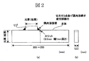
- Explanatory drawing which shows typically the dimension shape of the 3 point bending fillet welded joint fatigue test piece with a notch used for a fatigue test.
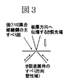
- Explanatory drawing which shows typically the generation
- the thick steel plate according to the present invention has a compressive residual stress of 100 MPa or more that is perpendicular to the plate thickness direction within a range of 4 mm in the plate thickness direction from both sides or one side of the rolled surface of the steel plate.
- the range of the compressive residual stress extends beyond 4 mm from the surface to the inside of the plate thickness, the compressive residual stress in the vicinity of the surface portion where fatigue cracks occur due to the balance of internal stress decreases, so The range is 4 mm from both sides or one side in the plate thickness direction.
- Compressive residual stress in the direction perpendicular to the thickness direction within the above range is 100 MPa or more. In order to suppress the propagation of fatigue cracks, it is effective to apply a compressive stress in a direction perpendicular to the crack surface. Since the present invention targets cracks propagating in the plate thickness direction, the compression direction of the compressive residual stress is set to a direction perpendicular to the plate thickness direction.
- the compressive residual stress is less than 100 MPa, the fatigue crack propagation rate is reduced, but a remarkable effect cannot be obtained to the extent that the fatigue life is improved.
- it is 150 MPa or more.
- the compressive residual stress in the direction perpendicular to the plate thickness direction in the steel plate exceeding the range of 4 mm in the plate thickness direction from both sides or one side of the rolled surface of the steel plate is not particularly specified, but is usually in the range of up to 4 mm in the plate thickness direction. Smaller size.
- the steel plate according to the present invention has both strength and toughness (tensile strength TS: 490 MPa or more, absorbed energy at ⁇ 40 ° C .: 100 J or more as Charpy impact value for collecting a thickness of 1/4) for a welded steel structure. Therefore, the preferred component composition and production conditions are as follows. [Component Composition] In the description, “%” is “mass%”.
- C 0.03-0.15%
- C is an element having an effect of increasing the strength of steel, and in order to ensure a desired high strength, it is preferably contained in an amount of 0.03% or more. Heat-affected zone toughness decreases. For this reason, C is preferably limited to a range of 0.03 to 0.15%.
- Si 1.0% or less
- Si is an element that acts as a deoxidizer and has a function of increasing the strength of steel by solid solution. In order to acquire such an effect, it is desirable to contain 0.01% or more. On the other hand, the content exceeding 1.0% lowers the weld heat affected zone toughness. For this reason, it is preferable to limit Si to 1.0% or less. In addition, More preferably, it is 0.50% or less.
- Mn 1.0 to 2.0%
- Mn is an element that has the effect of increasing the strength of steel. In order to ensure a desired high strength, Mn is preferably contained in an amount of 1.0% or more. There is concern about a reduction in material toughness. For this reason, Mn is preferably limited to a range of 1.0 to 2.0%. More preferably, it is 0.9 to 1.60%.
- Ti 0.005 to 0.05%
- Nb 0.001 to 0.05%
- Ti and Nb are elements that increase the strength through precipitation strengthening and suppress the growth of austenite grains during heating and contribute to the refinement of the steel sheet structure. In the present invention, one or two are included.
- Ti forms carbides and nitrides, contributes to the refinement of austenite grains during steel plate production, suppresses crystal grain coarsening in the weld heat affected zone, and improves the weld heat affected zone toughness. In order to acquire such an effect, it is preferable to contain 0.005% or more. On the other hand, the content exceeding 0.05% reduces toughness. For this reason, Ti is preferably limited to a range of 0.005 to 0.05%. More preferably, it is 0.005 to 0.02%.
- Nb like Ti, increases the strength through precipitation strengthening, further refines the structure, suppresses recrystallization of austenite, and promotes the effect of rolling to form the desired structure.
- it is preferable to contain 0.001% or more. However, if it exceeds 0.05%, the structure tends to become needle-like and the toughness tends to decrease.
- Nb is preferably limited to a range of 0.001 to 0.05%. More preferably, it is 0.02 to 0.05%.
- Al 0.1% or less
- Al is an element that acts as a deoxidizer and contributes to refinement of crystal grains, and can be contained as necessary. In order to acquire such an effect, it is desirable to contain 0.015% or more, However, Excess content exceeding 0.1% will lead to the fall of toughness. For this reason, when it contained, Al was limited to 0.1% or less. In addition, Preferably it is 0.08% or less.
- N 0.0035 to 0.0075%
- N is an element necessary for securing the necessary amount of TiN. If it is less than 0.0035%, a sufficient amount of TiN cannot be obtained, and if it exceeds 0.0075%, it is solidified in the region where TiN is dissolved by the welding heat cycle. The amount of dissolved N increases, and in any case, the toughness of the welded portion is remarkably reduced, so the content is made 0.0075% or less.
- 1 type (s) or 2 or more types of Cu, Ni, Cr, Mo, V, W, Zr, B, and Ca can be contained.
- Cu, Ni, Cr, Mo, V, W, Zr, and B are elements that improve the strength and toughness of the steel, and contain one or more kinds depending on the desired properties.
- Cu contributes to steel strength increase mainly through precipitation strengthening. In order to acquire such an effect, it is desirable to contain 0.01% or more, but when it exceeds 0.5%, precipitation strengthening is excessive and toughness is lowered. For this reason, when it contains, it is preferable to limit Cu to 0.5% or less. In addition, More preferably, it is 0.35% or less. Ni increases the strength of steel and contributes to improved toughness.
- Ni acts effectively to prevent cracking during hot rolling with Cu.
- it is desirable to contain 0.1% or more.
- it is preferable to limit Ni to 2.0% or less.
- More preferably, it is 0.05% or more.
- Cr increases the amount of pearlite and contributes to an increase in steel strength. In order to acquire such an effect, it is desirable to contain 0.01% or more, but inclusion exceeding 0.5% reduces the toughness of a welded part. For this reason, when contained, Cr is preferably limited to 0.5% or less. More preferably, the content is 0.01 to 0.2%.
- Mo contributes to increasing the strength of steel. In order to acquire such an effect, it is desirable to contain 0.01% or more, but inclusion exceeding 0.5% reduces the toughness of a welded part. For this reason, when it contains, it is preferable to limit Mo to 0.5% or less. More preferably, the content is 0.01 to 0.08%.
- V contributes to increasing the strength of steel through solid solution strengthening and precipitation strengthening. In order to acquire such an effect, it is desirable to contain 0.001% or more, but the content exceeding 0.1% remarkably lowers the base metal toughness and weldability. For this reason, it is preferable to limit V to 0.1% or less. More preferably, it is 0.05 to 0.1%.
- W contributes to an increase in steel strength, especially at high temperatures. In order to acquire such an effect, it is desirable to contain 0.1% or more, but if it contains more than 0.5%, the toughness of the welded portion is lowered. In addition, a large amount of expensive W causes a material cost to rise. For this reason, when contained, W is preferably limited to 0.5% or less. More preferably, it is 0.2 to 0.4%.
- Zr contributes to increasing the strength of the steel and improves the resistance to plating cracking in the galvanized material.
- B contributes to increasing the strength of the steel through improving hardenability, and precipitates as BN during rolling, contributing to refinement of ferrite grains after rolling.
- Ca 0.0005% to 0.0030%
- Ca is an element having an effect of improving toughness by fixing S. In order to exert such an effect, it is necessary to contain at least 0.0005%, but even if it exceeds 0.0030%, the effect is saturated, so 0.0005% to 0.0030% And
- the balance other than the above components is Fe and inevitable impurities, and P: 0.035% or less and S: 0.035% or less are acceptable.
- the manufacturing method of steel materials is not specifically limited.
- the molten steel having the above composition is melted using a conventional melting furnace such as a converter, and is made into a steel material such as a slab by a conventional method such as a continuous casting method, and heated to a temperature of 1000 to 1250 ° C.
- the heating temperature of the steel material is preferably limited to a temperature in the range of 1000 to 1250 ° C. In addition, more preferably, it is 1200 degrees C or less from a viewpoint of a toughness improvement.
- Hot rolling is performed at a temperature of (Ar3 point +50) ° C. or higher with a cumulative reduction of 30% or more, and in combination with the cooling conditions described later, 4 mm from both sides or one side of the rolled surface of the steel plate in the thickness direction. In the range up to this point, compressive residual stress in the direction perpendicular to the thickness direction of 100 MPa or more is introduced.
- Ar3 point is calculated
- required by Ar3 (degreeC) 910-273 * C-74 * Mn-57 * Ni-16 * Cr-9 * Mo-5 * Cu (each element is content (mass%)), for example. Is possible.
- a steel plate with a thickness of 50 mm or more is used. Compressive residual stress improves fatigue properties, but reduces buckling performance, and the reduction is more noticeable for steel sheets with thinner plate thickness, and if the plate thickness is less than 50 mm, there is a concern that the buckling performance of the steel plate itself may decrease.
- the thickness is 50 mm or more.
- the present invention does not limit rolling outside the specified temperature range, and it is possible to perform rough rolling performed at a high temperature after slab heating.
- welding heat input (kJ / cm) and a lamination method are defined as welding conditions for a fillet joint of a thick steel plate having excellent fatigue resistance in the thickness direction.
- Welding heat input (sometimes simply referred to as heat input) is 30 kJ / cm or less.
- the welding heat input is 30 kJ / cm or less
- the compressive residual stress at the weld toe becomes high, and the effect of improving fatigue characteristics cannot be obtained. Therefore, the number of layers is 3 or less and 6 or less.
- the welding method is not specified. Hand welding, MIG welding (metal inert gas welding), CO 2 welding (carbon dioxide welding), etc. can be applied.
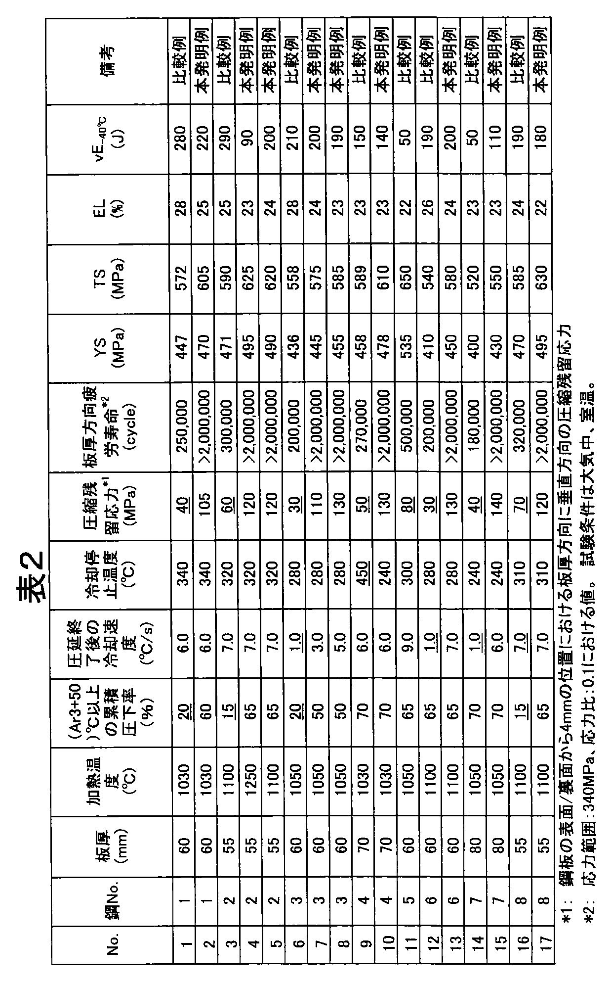
- the steel material having the composition shown in Table 1 was hot-rolled under the conditions shown in Table 2 to obtain a thick steel plate having a thickness of 55 to 70 mm. These thick steel plates were subjected to residual stress measurement, tensile test, toughness test, and fatigue test.
- the test method was as follows.
- the tensile test was performed in accordance with JIS Z 2241 (1998), and YS: yield strength or 0.2% proof stress TS: tensile strength and elongation EL were determined to evaluate tensile properties during static tension.
- (3) Toughness test V-notch test specimens were collected from the obtained thick steel plates in accordance with the provisions of JIS Z 2242 (2005) so that the longitudinal direction was parallel to the rolling direction, and absorption at ⁇ 40 ° C. Energy was determined and toughness was evaluated.
- the V notch test piece was extract
- a fatigue test specimen size: plate thickness (the original thickness of the steel plate) x 12.5 mm x 300 ⁇ ) so that the propagation direction of fatigue cracks is the plate thickness direction.
- 350 mm [plate thickness direction dimension ⁇ rolling vertical direction dimension ⁇ rolling direction dimension]) was collected.
- the test piece is a notched three-point bending fatigue test piece having the dimensions shown in FIG. 1, and the bending span at the time of the fatigue test is 4 times the plate thickness. In this case, when the dimension in the rolling direction was 300 mm and the plate thickness was 80 mm, the dimension in the rolling direction was 350 mm.
- the obtained results are shown in Table 2.
- the compressive residual stress is lowest at a position 4 mm from the front surface / back surface (in the range from the front surface / back surface to 4 mm).
- the compressive residual stress in the direction perpendicular to the plate thickness direction is 100 MPa or more, and the steel plate has excellent fatigue resistance in the plate thickness direction without deterioration in toughness.
- the comparative examples No.
- the compressive residual stress in the direction perpendicular to the plate thickness direction is less than 100 MPa, and the fatigue resistance in the plate thickness direction. Is inferior.
- the amount of C exceeds 0.23 mass%, the upper limit of the preferable content of the present invention, in the component composition of steel, so that the compressive residual stress is less than 100 MPa and the fatigue resistance in the thickness direction is inferior.
- a fillet welded joint was prepared using the thick steel plate 2 with excellent fatigue properties in the thickness direction with a thickness of 55 to 70 mm, whose chemical composition is shown in Table 3 and the manufacturing conditions and properties shown in Table 4, and the shape is shown in FIG.
- a three-point bending fatigue test was conducted using a notched three-point bending fillet welded joint fatigue test piece. The test method for confirming the structure, mechanical properties, and plate thickness direction fatigue properties of the thick steel plate 2 was performed in the same manner as in Example 1.
- a fillet welded joint was produced under the conditions shown in FIG. 4, and a fatigue test was performed.
- Table 5 shows the results obtained with the thick steel plate 2.
Landscapes
- Chemical & Material Sciences (AREA)
- Engineering & Computer Science (AREA)
- Materials Engineering (AREA)
- Mechanical Engineering (AREA)
- Metallurgy (AREA)
- Organic Chemistry (AREA)
- Physics & Mathematics (AREA)
- Thermal Sciences (AREA)
- Crystallography & Structural Chemistry (AREA)
- Heat Treatment Of Steel (AREA)
Abstract
圧力容器等の溶接鋼構造物用として好適な、板厚方向の耐疲労特性に優れた厚鋼板およびその製造方法、その厚鋼板を用いた隅肉溶接継手を提供する。具体的には、鋼板の圧延面の両側または片側から板厚方向に4mmまでの範囲において、板厚方向に直角となる圧縮残留応力が100MPa以上で、好ましくは質量%で、C:0.03~0.15%、Si:1.0%以下、Mn:1.0~2.0%を含み、さらにTi:0.005~0.05%、Nb:0.001~0.05%の1種または2種、Al:0.1%以下更に、Cu、Ni、Cr、Mo、V、W、Zr、Ca、Bの1種または2種以上を含有する組成とする厚鋼板およびその製造方法、その厚鋼板を用いた隅肉溶接継手である。
Description
本発明は、船舶(ships)、海洋構造物(marine structure)、橋梁(bridge)、建築物(construction)、圧力容器(pressure vessel)等の溶接鋼構造物(welded steel structure)用として好適な板厚方向の耐疲労特性(fatigue resistandce)に優れた厚鋼板(steel plate)およびその製造方法、その厚鋼板を用いた隅肉溶接継手に関する。
船舶、海洋構造物、橋梁、建築物、圧力容器などの溶接鋼構造物に使用される鋼板は、強度(strength)、靭性(toughness)などの機械的性質(mechanical property)や溶接性(weldability)に優れていることはもちろんであるが、稼動時における定常の繰返し荷重(steady cyclic load)や、風(wind)、地震(earthquake)等の震動に起因する非定常の繰返し荷重(unsteady cyclic load)に対しても、構造物の構造安全性(structural safety)を確保できる特性を有することが要求される。特に近年では、鋼板に対して、耐疲労特性に優れることが強く要求されている。
溶接鋼構造物では、溶接止端部等に多数の応力集中部が存在するが、溶接止端部には応力が集中しやすく、また、引張の残留応力も作用するため、繰返し荷重が作用した場合には、溶接止端部(weld toe)から疲労亀裂(fatigue crack)が発生しやすく、溶接止端部が疲労亀裂の発生源となることが多い。
このような疲労亀裂の発生を防止するために、止端部形状の改善や、圧縮の残留応力(compressive residual stress)の導入などの方策が知られている。しかし、溶接鋼構造物には多数の溶接止端部が存在するため、溶接止端部ごとに、上記した疲労亀裂の発生を防止する方策を実行することは、多大の労力と時間を必要とし、施工工数の増加や、施工コストの高騰を招く。
そこで、このような疲労亀裂の発生を防止する方策に代えて、使用する鋼板自体の耐疲労特性を向上させて、溶接鋼構造物の耐疲労特性の向上を図ることが考えられている。鋼板自体の耐疲労特性を向上させることにより、疲労亀裂の成長が抑制されて、溶接鋼構造物の疲労寿命(fatigue life)の延長が可能となる。
このような要望に対し、例えば特許文献1では、鋼板圧延方向に延在する縞状の第二相が母相内に5~50%の面積率で散在する微視組織(英文すぺる?microstructure)を有し、第二相の硬さ(hardness)HVが母相の硬さHVより30%以上高い、耐疲労亀裂進展特性(fatigue crack propagation properties)の良好な鋼板が提案されている。
特許文献1に記載された技術は、母相中に、硬さの高い第二相を分散させ、疲労亀裂が硬い第二相付近に達すると亀裂の伝播が大幅に遅延する現象により、鋼板の耐疲労亀裂伝播特性を向上させるもので、第二相のアスペクト比(aspect ratio)を4以上とすることが好ましいとしている。このような鋼板を、表面から疲労亀裂が発生し伝播する大型構造物に使用すれば、特別な配慮を必要とせず、高い疲労亀裂伝播阻止特性を大型構造物に付与可能であることが記載されている。
また、溶接継手の中では、角回し溶接(box arc weld)、十字溶接(cruciform arc weld)、カバープレート溶接(cover plate weld)、スタッド溶接(stud weld)などの隅肉溶接継手(fillet welded joint)の疲労強度(fatigue strength)が最も低いことが知られ、特に最近の大型コンテナ船(container vessels)等に適用される極厚鋼板(heavy gauge steel)の隅肉溶接継手における疲労強度の改善が喫緊の課題(urgent issue)とされている。隅肉溶接継手の場合、溶接止端部から発生した疲労き裂は板厚方向に進展するため板厚方向の耐疲労特性に優れた鋼板を用いることが継手としての耐疲労特性を向上させるために有効である。
また、特許文献2には、質量%で、C:0.015~0.20%、Si:0.05~2.0%、Mn:0.1~2.0%、P:0.05%以下、S:0.02%以下を含有し、残部Feおよび不可避的不純物よりなり、X線で測定した板厚方向の(200)回折強度比(diffracted intensity ratio)が2.0~15.0で、且つ回復フェライト粒(recovery ferrite grain)または再結晶フェライト粒(recrystallized ferrite grain)の面積率(area ratio)が15~40%である、板厚方向の疲労き裂伝播速度(fatigue crack growth rate)が低い厚鋼板が記載されている。
特許文献3には、鋼板を焼入れ、焼きならし等のオフライン熱処理、或いは、直接焼入れ、加速冷却等のオンライン熱処理を行った後、Ac1点以下の温度で焼き戻しを行い、その後の冷却する場合に、冷却過程における鋼板表面と鋼板板厚中心部の温度差の最大値を200℃以上とする強制冷却を行うことにより、鋼板表面に圧縮残留応力が付与され、優れた疲労強度の鋼板が得られるとしている。
しかしながら、特許文献1に記載された技術では、疲労亀裂伝播速度を低くし、疲労亀裂の伝播を著しく遅滞させるため、母相に比べ第二相の硬さを高くし、さらに硬質の第二相を多量に分散させる必要がある。このため、鋼板の延性(ductility)、靭性の低下が著しくなるという問題が生じる。鋼板の延性、靭性の低下は、多量の合金元素の含有で防止できる場合もあるが、多量の合金元素の含有は、材料コストの高騰を招くという問題を避けられない。
また、特許文献2に記載された技術では、板厚方向の(200)回折強度比を2.0以上とし、すなわち、(100)面が板面に平行に揃った集合組織(texture)を発達させ、疲労亀裂先端(fatigue crack tip)で種々のすべり系(slip system)を活動させ転位(dislocation)同士の干渉(interference)を生じさせ、亀裂の伝播を抑制して板厚方向の疲労亀裂伝播速度を低くしている。しかし、(100)面は劈開面(cleavage plane)であり、板面に平行に(100)面が揃った厚鋼板では、板厚方向の靭性が劣化するという問題を残していた。
更に、特許文献1、2記載の技術は、疲労亀裂伝播速度は低減するが、疲労亀裂発生寿命を含めたトータル(total)の疲労寿命は顕著には増加しないという根本的な問題を有していた。、
更に、特許文献1、2記載の技術は、疲労亀裂伝播速度は低減するが、疲労亀裂発生寿命を含めたトータル(total)の疲労寿命は顕著には増加しないという根本的な問題を有していた。、
上述したように、特許文献1、2に記載された耐疲労特性に優れた厚鋼板は溶接構造物用としては、コストや性能面で改善すべき余地があり、一方、隅肉溶接継手の製作においても、継手としての耐疲労特性を向上する溶接法は明らかにされていない。
また、特許文献3に記載された技術では、鋼板表面に圧縮残留応力を付与するのに、焼戻し処理が必須で、生産性の良い圧延ままでの鋼板提供が不可能という問題を残していた。
本発明は、かかる従来技術の問題を有利に解決し、溶接鋼構造物向けとして好適な強度と靭性を備えた、板厚方向の耐疲労特性に優れた厚鋼板およびその製造方法を提供することを目的とする。
また、特許文献3に記載された技術では、鋼板表面に圧縮残留応力を付与するのに、焼戻し処理が必須で、生産性の良い圧延ままでの鋼板提供が不可能という問題を残していた。
本発明は、かかる従来技術の問題を有利に解決し、溶接鋼構造物向けとして好適な強度と靭性を備えた、板厚方向の耐疲労特性に優れた厚鋼板およびその製造方法を提供することを目的とする。
また、本発明は板厚方向の耐疲労特性に優れた厚鋼板を用いた隅肉継手で耐疲労特性に優れた隅肉溶接継手を提供することを目的とする。
本発明者らは、鋼板の延性・靭性の低下および板厚方向の靭性低下を伴うことなく、生産性のよい圧延ままで疲労特性を向上させるため、鋼板の内部残留応力に着目して鋭意研究を重ね、以下の知見を得た。
(1)板厚方向の疲労特性は、鋼板の圧延面の両側または片側から板厚方向に4mmまでの範囲において、板厚方向に直角となる圧縮残留応力を100MPa以上とすることで、向上する。
(2)上記圧縮残留応力を備えた鋼板は、板厚中央部の温度を(Ar3点+50)℃以上として累積圧下率30%以上の熱間圧延を行い、その後、3℃/s以上の冷却速度で350℃以下まで冷却すると圧延ままで(焼戻し処理無しで)で製造可能である。
なお、本発明は、板厚:50mm以上の鋼板を対象とし、「耐疲労特性に優れた」とは、図1に示す寸法形状の3点曲げ疲労試験片を用いて、応力比が0.1となる条件で疲労試験を実施して、板厚方向の疲労寿命を求め、応力範囲340MPaでの疲労寿命が200万回以上である場合とする。
(1)板厚方向の疲労特性は、鋼板の圧延面の両側または片側から板厚方向に4mmまでの範囲において、板厚方向に直角となる圧縮残留応力を100MPa以上とすることで、向上する。
(2)上記圧縮残留応力を備えた鋼板は、板厚中央部の温度を(Ar3点+50)℃以上として累積圧下率30%以上の熱間圧延を行い、その後、3℃/s以上の冷却速度で350℃以下まで冷却すると圧延ままで(焼戻し処理無しで)で製造可能である。
なお、本発明は、板厚:50mm以上の鋼板を対象とし、「耐疲労特性に優れた」とは、図1に示す寸法形状の3点曲げ疲労試験片を用いて、応力比が0.1となる条件で疲労試験を実施して、板厚方向の疲労寿命を求め、応力範囲340MPaでの疲労寿命が200万回以上である場合とする。
また、(4)鋼板の板厚方向と直角方向の圧縮残留応力を、鋼板の圧延面の両側または片側から板厚方向に4mmまでの範囲において、100MPa以上とすることも有効である。
また、(5)隅肉溶接継手作製の際の溶接入熱と積層数を制限することが、隅肉溶接部の疲労強度を向上させるのに有効である。
尚、本発明は板厚50mm以上の厚鋼板の隅肉溶接継手を対象とする。板厚50mm未満では、板厚効果による疲労強度の低下はそれほど顕著ではなく、また、過去の多くの疲労試験データベースに基づいた各種疲労設計曲線に準拠すれば、本発明を用いなくとも耐疲労安全性は確保される。「耐疲労特性に優れた」とは、図1に示す寸法形状の切欠付3点曲げ隅肉溶接継手疲労試験片を用いて、応力比が0.1となる条件で疲労試験を実施して、板厚方向の疲労寿命を求め、応力範囲340MPaでの疲労寿命が25万回以上の場合とする。
本発明は、得られた知見に、さらに検討を加えて完成されたもので、すなわち、本発明の要旨は次ぎのとおりである。
(1)鋼板の圧延面の両側または片側から板厚方向に4mmまでの範囲において、板厚方向に直角となる圧縮残留応力が100MPa以上であることを特徴とする板厚方向の耐疲労特性に優れた厚鋼板。
(2)前記厚鋼板が、質量%で、C:0.03~0.15%、Si:1.0%以下、Mn:1.0~2.0%を含み、さらにTi:0.005~0.05%、Nb:0.001~0.05%の1種または2種、N:0.0035~0.0075%を含有し、残部Feおよび不可避的不純物からなる組成を有することを特徴とする(1)に記載の厚鋼板。
(3)更に、質量%で、Cu:0.01~0.5%、Ni:2.0%以下、Cr:0.01~0.5%、Mo:0.01~0.5%、V:0.001~0.1%、W:0.5%以下、Zr:0.5%以下、Ca:0.0005~0.0030%、B:0.0005~0.0020%の1種または2種以上を含有する組成とすることを特徴とする(2)に記載の厚鋼板。
(4)更に、質量%で、Al:0.1%以下を含有する組成とすることを特徴とする(2)または(3)に記載の厚鋼板。
(5)(2)ないし(4)のいずれか一つに記載の化学成分を有する鋼素材を、1000~1250℃の温度に加熱後、板厚中央部が(Ar3点+50)℃以上となる温度域で累積圧下率30%以上の熱間圧延を行い、その後、3℃/s以上の冷却速度にて350℃以下まで冷却することを特徴とする板厚方向の耐疲労特性に優れた厚鋼板の製造方法。
(6)板厚50mm以上の板厚方向の耐疲労特性に優れた厚鋼板の隅肉部を、入熱30kJ/cm以下、3層6パス以下の積層で溶接することを特徴とする、疲労強度の優れた隅肉溶接継手。
(7)前記板厚50mm以上の厚鋼板の圧延面の両側または片側から板厚方向に4mmまでの範囲において、板厚方向と直角方向の圧縮残留応力が100MPa以上であることを特徴とする(6)に記載の疲労強度の優れた隅肉溶接継手。
本発明は、得られた知見に、さらに検討を加えて完成されたもので、すなわち、本発明の要旨は次ぎのとおりである。
(1)鋼板の圧延面の両側または片側から板厚方向に4mmまでの範囲において、板厚方向に直角となる圧縮残留応力が100MPa以上であることを特徴とする板厚方向の耐疲労特性に優れた厚鋼板。
(2)前記厚鋼板が、質量%で、C:0.03~0.15%、Si:1.0%以下、Mn:1.0~2.0%を含み、さらにTi:0.005~0.05%、Nb:0.001~0.05%の1種または2種、N:0.0035~0.0075%を含有し、残部Feおよび不可避的不純物からなる組成を有することを特徴とする(1)に記載の厚鋼板。
(3)更に、質量%で、Cu:0.01~0.5%、Ni:2.0%以下、Cr:0.01~0.5%、Mo:0.01~0.5%、V:0.001~0.1%、W:0.5%以下、Zr:0.5%以下、Ca:0.0005~0.0030%、B:0.0005~0.0020%の1種または2種以上を含有する組成とすることを特徴とする(2)に記載の厚鋼板。
(4)更に、質量%で、Al:0.1%以下を含有する組成とすることを特徴とする(2)または(3)に記載の厚鋼板。
(5)(2)ないし(4)のいずれか一つに記載の化学成分を有する鋼素材を、1000~1250℃の温度に加熱後、板厚中央部が(Ar3点+50)℃以上となる温度域で累積圧下率30%以上の熱間圧延を行い、その後、3℃/s以上の冷却速度にて350℃以下まで冷却することを特徴とする板厚方向の耐疲労特性に優れた厚鋼板の製造方法。
(6)板厚50mm以上の板厚方向の耐疲労特性に優れた厚鋼板の隅肉部を、入熱30kJ/cm以下、3層6パス以下の積層で溶接することを特徴とする、疲労強度の優れた隅肉溶接継手。
(7)前記板厚50mm以上の厚鋼板の圧延面の両側または片側から板厚方向に4mmまでの範囲において、板厚方向と直角方向の圧縮残留応力が100MPa以上であることを特徴とする(6)に記載の疲労強度の優れた隅肉溶接継手。
本発明によれば、板厚方向の耐疲労特性に優れた板厚50mm以上の厚鋼板を延性、靭性を損なわずに、容易に、しかも安価に製造でき、産業上格段の効果を奏する。
また、本発明によれば、疲労強度が特に問題となる板厚50mm以上の厚鋼板の隅肉溶接部の疲労特性を溶接構造物としての延性、靭性を備えた厚鋼板を用いて容易に、且つ安価に向上でき、産業上格段の効果を奏する。
また、本発明によれば、疲労強度が特に問題となる板厚50mm以上の厚鋼板の隅肉溶接部の疲労特性を溶接構造物としての延性、靭性を備えた厚鋼板を用いて容易に、且つ安価に向上でき、産業上格段の効果を奏する。
以下、本発明で規定する鋼板の圧縮残留応力、好ましい成分組成、製造条件について説明する。
[鋼板の圧縮残留応力]
本発明に係る厚鋼板は、鋼板の圧延面の両側または片側から板厚方向に4mmまでの範囲に板厚方向に直角となる、100MPa以上の圧縮残留応力を備える。
[鋼板の圧縮残留応力]
本発明に係る厚鋼板は、鋼板の圧延面の両側または片側から板厚方向に4mmまでの範囲に板厚方向に直角となる、100MPa以上の圧縮残留応力を備える。
溶接構造物の製作において鋼板表面部への仮付溶接あるいは打ち傷等が避けられず、鋼板のごく表裏面部においては圧縮残留応力が損なわれるので、100MPa以上の圧縮残留応力の存在する範囲を鋼板の圧延面の両側または片側から板厚方向に4mmとする。
一方、圧縮残留応力の範囲が表面から4mmを超えて板厚の内部にまで拡がると、内部応力のバランスから疲労亀裂が発生する表面部付近の圧縮残留応力が小さくなるため、鋼板の圧延面の両側または片側から板厚方向に4mmまでの範囲とする。
上記範囲内における板厚方向に直角方向の圧縮残留応力は100MPa以上とする。疲労亀裂の伝播抑制には、亀裂面と直角方向に圧縮応力を作用させることが有効である。本発明は板厚方向に伝播する亀裂を対象とするので、圧縮残留応力の圧縮方向を板厚方向と直角方向とする。
圧縮残留応力が100MPa未満では、疲労亀裂伝播速度は低減されるものの、疲労寿命の向上につながるほど顕著な効果は得られないため、100MPa以上とする。なお、より好ましくは、150MPa以上である。鋼板の圧延面の両側または片側から板厚方向に4mmまでの範囲を超える鋼板内の板厚方向に直角方向の圧縮残留応力については特に規定しないが、通常、板厚方向に4mmまでの範囲内より小さい大きさとなる。
本発明に係る厚鋼板に溶接鋼構造物用としての強度と靭性(引張強さTS:490MPa以上、板厚1/4採取のシャルピー衝撃値として−40℃における吸収エネルギー:100J以上)を兼備させるための、好ましい、成分組成と製造条件は以下の様である。
[成分組成] 説明において%は質量%とする。
[成分組成] 説明において%は質量%とする。
C:0.03~0.15%
Cは、鋼の強度を増加させる作用を有する元素であり、所望の高強度を確保するためには、0.03%以上含有することが好ましいが、0.15%を超えて含有すると、溶接熱影響部靭性が低下する。このため、Cは0.03~0.15%の範囲に限定することが好ましい。
Cは、鋼の強度を増加させる作用を有する元素であり、所望の高強度を確保するためには、0.03%以上含有することが好ましいが、0.15%を超えて含有すると、溶接熱影響部靭性が低下する。このため、Cは0.03~0.15%の範囲に限定することが好ましい。
Si:1.0%以下
Siは、脱酸剤として作用するとともに、固溶して鋼の強度を増加させる作用を有する元素である。このような効果を得るためには、0.01%以上含有することが望ましい。一方、1.0%を超える含有は、溶接熱影響部靭性を低下させる。このため、Siは1.0%以下に限定することが好ましい。なお、より好ましくは0.50%以下である。
Siは、脱酸剤として作用するとともに、固溶して鋼の強度を増加させる作用を有する元素である。このような効果を得るためには、0.01%以上含有することが望ましい。一方、1.0%を超える含有は、溶接熱影響部靭性を低下させる。このため、Siは1.0%以下に限定することが好ましい。なお、より好ましくは0.50%以下である。
Mn:1.0~2.0%
Mnは、鋼の強度を増加させる作用を有する元素であり、所望の高強度を確保するためには、1.0%以上含有することが好ましいが、2.0%を超えて含有すると、母材靭性の低下が懸念される。このため、Mnは1.0~2.0%の範囲に限定することが好ましい。なお、より好ましくは0.9~1.60%である。
Ti:0.005~0.05%、Nb:0.001~0.05%の1種または2種
Mnは、鋼の強度を増加させる作用を有する元素であり、所望の高強度を確保するためには、1.0%以上含有することが好ましいが、2.0%を超えて含有すると、母材靭性の低下が懸念される。このため、Mnは1.0~2.0%の範囲に限定することが好ましい。なお、より好ましくは0.9~1.60%である。
Ti:0.005~0.05%、Nb:0.001~0.05%の1種または2種
Ti、Nbは、析出強化を介して強度を増加させるとともに、加熱時のオーステナイト粒の成長を抑制し鋼板組織の微細化に寄与する元素であり、本発明では1種または2種を含有する。
Tiは、炭化物、窒化物を形成し、鋼板製造時のオーステナイト粒の微細化に寄与するとともに、溶接熱影響部の結晶粒粗大化を抑制し、溶接熱影響部靭性を向上させる。このような効果を得るためには、0.005%以上含有することが好ましい。一方、0.05%を超える含有は、靭性を低下させる。このため、Tiは0.005~0.05%の範囲に限定することが好ましい。なお、より好ましくは0.005~0.02%である。
Nbは、Tiと同様に、析出強化を介して強度を増加させ、さらに組織を微細化するとともに、オーステナイトの再結晶を抑制し、所望の組織を形成するための圧延による効果を促進する作用を有する。このような効果を得るためには、0.001%以上含有することが好ましいが、0.05%を超える含有は、組織が針状化し靭性が低下する傾向となる。このため、Nbは0.001~0.05%の範囲に限定することが好ましい。なお、より好ましくは0.02~0.05%である。
Al:0.1%以下
Alは、脱酸剤として作用するとともに、結晶粒の微細化にも寄与する元素であり、必要に応じて含有できる。このような効果を得るためには、0.015%以上含有することが望ましいが、0.1%を超える過剰の含有は、靭性の低下に繋がる。このため、含有する場合には、Alは0.1%以下に限定した。なお、好ましくは0.08%以下である。
Alは、脱酸剤として作用するとともに、結晶粒の微細化にも寄与する元素であり、必要に応じて含有できる。このような効果を得るためには、0.015%以上含有することが望ましいが、0.1%を超える過剰の含有は、靭性の低下に繋がる。このため、含有する場合には、Alは0.1%以下に限定した。なお、好ましくは0.08%以下である。
N:0.0035~0.0075%
Nは、TiNの必要量を確保するために必要な元素で、0.0035%未満では十分なTiN量が得られず、0.0075%を超えると溶接熱サイクルによってTiNが溶解する領域において固溶N量が増加して、いずれの場合も溶接部の靭性を著しく低下させるため、0.0075%以下とする。
Nは、TiNの必要量を確保するために必要な元素で、0.0035%未満では十分なTiN量が得られず、0.0075%を超えると溶接熱サイクルによってTiNが溶解する領域において固溶N量が増加して、いずれの場合も溶接部の靭性を著しく低下させるため、0.0075%以下とする。
更に特性を向上させる場合、上記基本成分に加えて、Cu、Ni、Cr、Mo、V、W、Zr、B、Caの1種または2種以上を含有することができる。
Cu:0.01~0.5%、Ni:2.0%以下、Cr:0.01~0.5%、Mo:0.01~0.5%、V:0.001~0.1%、W:0.5%以下、Zr:0.5%以下、Ca:0.0005~0.0030%、B:0.0005~0.0020%の1種または2種以上
Cu、Ni、Cr、Mo、V、W、Zr、Bは、鋼の強度および靭性を向上させる元素で、所望する特性に応じて1種または2種以上を含有する。
Cu:0.01~0.5%、Ni:2.0%以下、Cr:0.01~0.5%、Mo:0.01~0.5%、V:0.001~0.1%、W:0.5%以下、Zr:0.5%以下、Ca:0.0005~0.0030%、B:0.0005~0.0020%の1種または2種以上
Cu、Ni、Cr、Mo、V、W、Zr、Bは、鋼の強度および靭性を向上させる元素で、所望する特性に応じて1種または2種以上を含有する。
Cuは、主として析出強化を介して鋼の強度増加に寄与する。このような効果を得るためには、0.01%以上含有することが望ましいが、0.5%を超える含有は、析出強化が過多となり、靭性が低下する。このため、含有する場合には、Cuは0.5%以下に限定することが好ましい。なお、より好ましくは0.35%以下である。 Niは、鋼の強度を増加するとともに、靭性向上にも寄与する。
Niは、Cuによる熱間圧延時の割れを防止するために有効に作用する。このような効果を得るためには、0.1%以上含有することが望ましい。しかし、2.0%を超えて多量に含有しても、効果が飽和し含有量に見合う効果が期待できなくなり経済的に不利となるとともに、Niは高価な元素であり多量の含有は材料コストの高騰を招く。このため、含有する場合には、Niは2.0%以下に限定することが好ましい。なお、より好ましくは0.05%以上である。
Crは、パーライト量を増加させ、鋼の強度増加に寄与する。このような効果を得るためには、0.01%以上含有することが望ましいが、0.5%を超える含有は、溶接部の靭性を低下させる。このため、含有する場合には、Crは0.5%以下に限定することが好ましい。なお、より好ましくは0.01~0.2%である。
Moは、鋼の強度増加に寄与する。このような効果を得るためには、0.01%以上含有することが望ましいが、0.5%を超える含有は、溶接部の靭性を低下させる。このため、含有する場合には、Moは0.5%以下に限定することが好ましい。なお、より好ましくは0.01~0.08%である。
Vは、固溶強化、析出強化を介して鋼の強度増加に寄与する。このような効果を得るためには、0.001%以上含有することが望ましいが、0.1%を超える含有は、母材靭性および溶接性を顕著に低下させる。このため、Vは0.1%以下に限定することが好ましい。なお、より好ましくは0.05~0.1%である。
Wは、鋼の強度増加、とくに高温の強度増加に寄与する。このような効果を得るためには、0.1%以上含有することが望ましいが、0.5%を超える多量の含有は、溶接部の靭性を低下させる。また、高価なWの多量含有は材料コストの高騰を招く。このため、含有する場合には、Wは0.5%以下に限定することが好ましい。なお、より好ましくは0.2~0.4%である。
Zrは、鋼の強度増加に寄与するとともに、亜鉛めっき処理材における耐めっき割れ性を向上させる。このような効果を得るためには0.01%以上含有することが望ましいが、0.5%を超える含有は、溶接部靭性を低下させる。このため、含有する場合には、0.5%以下に限定することが好ましい。なお、より好ましくは0.01~0.1%である。
Bは、焼入れ性の向上を介し鋼の強度増加に寄与するとともに、圧延中にBNとして析出し、圧延後のフェライト粒の微細化に寄与する。このような効果を得るためには、0.0005%以上含有することが望ましいが、0.0020%を超える含有は靭性を劣化させる。このため、含有する場合には、Bは0.0020%以下に限定することが好ましい。なお、より好ましくは0.001~0.003%である。
Ca:0.0005%~0.0030%
Caは、Sの固定による靭性改善効果を有する元素である。このような効果を発揮させるには少なくとも0.0005%は含有することが必要であるが、0.0030%を超えて含有しても効果が飽和するため、0.0005%~0.0030%とする。
Caは、Sの固定による靭性改善効果を有する元素である。このような効果を発揮させるには少なくとも0.0005%は含有することが必要であるが、0.0030%を超えて含有しても効果が飽和するため、0.0005%~0.0030%とする。
上記した成分以外の残部は、Feおよび不可避的不純物で、P:0.035%以下、S:0.035%以下が許容できる。
[製造条件]
スラブ等の鋼素材の製造方法は、とくに限定しない。上記組成の溶鋼を、転炉等の常用の溶製炉を用いて溶製し、連続鋳造法等の常用の方法で、スラブ等の鋼素材とし、1000~1250℃の温度に加熱する。
スラブ等の鋼素材の製造方法は、とくに限定しない。上記組成の溶鋼を、転炉等の常用の溶製炉を用いて溶製し、連続鋳造法等の常用の方法で、スラブ等の鋼素材とし、1000~1250℃の温度に加熱する。
加熱温度が1000℃未満では、所望の熱間圧延が困難となる。一方、1250℃を超える加熱温度では、表面酸化が顕著となり、また、結晶粒の粗大化が顕著となる。このため、鋼素材の加熱温度は、1000~1250℃の範囲の温度に限定することが好ましい。なお、より好ましくは、靭性向上の観点から、1200℃以下である。
加熱された鋼素材に、熱間圧延を施す。熱間圧延は、(Ar3点+50)℃以上の温度域において累積圧下率30%以上の圧延を行い、後述の冷却条件との組み合わせで、鋼板の圧延面の両側または片側から板厚方向に4mmまでの範囲に、100MPa以上の板厚方向に直角方向の圧縮残留応力を導入する。Ar3点は、例えば、Ar3(℃)=910−273×C−74×Mn−57×Ni−16×Cr−9×Mo−5×Cu(各元素は含有量(質量%))で求めることが可能である。
熱間圧延では、板厚50mm以上の鋼板とする。圧縮残留応力は、疲労特性を向上させるが、座屈性能を低下させ、その低下は板厚が薄い鋼板ほど顕著で板厚50mm未満では鋼板自体の座屈性能の低下が懸念されるため、板厚50mm以上とする。
尚、本発明は規定した温度域外での圧延を制限するものではなく、スラブ加熱後の高温で実施する粗圧延などを行うことが可能である。
圧延終了後、3℃/s以上の冷却速度にて350℃以下まで冷却する。冷却速度、冷却停止温度のどちらかが上記規定を外れると、鋼板の圧延面の両側または片側から板厚方向に4mmまでの範囲において、板厚方向に直角となる100MPa以上の圧縮残留応力が得られない。より好ましくは、5℃/s以上の冷却速度にて300℃以下まで冷却する。
本発明では、板厚方向の耐疲労特性に優れた厚鋼板の隅肉継手の溶接条件として溶接入熱(kJ/cm)と積層方法を規定する。溶接入熱(welding heat input)(単に、入熱と言う場合がある)は30kJ/cm以下とする。30kJ/cmを超える入熱で隅肉溶接すると、溶接の熱影響により、鋼板の組織あるいは内部残留応力の形態が変化し、板厚方向の耐疲労特性に優れた鋼板の疲労特性に悪影響を及ぼすため30kJ/cm以下とする。
また、溶接入熱30kJ/cm以下であっても3層や6パスを超える積層で隅肉溶接継手を作製すると、溶接止端部の圧縮残留応力が高くなり、疲労特性向上効果が得られなくなるため、積層は3層以下かつ6パス以下とする。なお、溶接法は特に規定しない。手溶接(hand welding)、MIG溶接(metal inert gas welding)、CO2溶接(carbon dioxide welding)などが適用できる。
表1に示す組成の鋼素材に、表2に示す条件で熱間圧延を施し、板厚55~70mmの厚鋼板とした。これら厚鋼板について、残留応力測定、引張試験、靭性試験、疲労試験を実施した。試験方法はつぎのとおりとした。
(1)残留応力測定
得られた厚鋼板から、X線による残留応力の測定用試験片(大きさ:板厚(鋼板元厚まま)×12.5mm×300mm[板厚方向寸法×圧延直角方向寸法×圧延方向寸法])を採取し、測定面[12.5mm×300mmの面]に電解研磨を施した後、板厚方向に4mmピッチでX線により板厚方向に直角方向の残留応力を測定した。板厚方向に4mmピッチで測定するライン数は5ラインとした。測定された5ラインの残留応力を各板厚位置毎に5点平均して求めた残留応力の板厚方向分布図から、表面/裏面から4mmの位置における残留応力(マイナスの値)を求め、その絶対値を、圧縮残留応力とした。
(2)引張試験
得られた厚鋼板から、JIS Z 2201(1998)の規定に準拠して、引張方向が鋼板の圧延方向と直角方向となるように、JIS 4号引張試験片(平行部径:14mm)を採取した。試験片の採取位置は、板厚の1/4位置とした。引張試験は、JIS Z 2241(1998)に準拠して行い、YS:降伏強さまたは0.2%耐力TS:引張強さ、伸びELを求め、静的引張時の引張特性を評価した。
(3)靭性試験
得られた厚鋼板から、JIS Z 2242(2005)の規定に準拠して、長手方向が圧延方向に平行となるように、Vノッチ試験片を採取し、−40℃における吸収エネルギーを求め、靭性を評価した。なお、Vノッチ試験片は、板厚の1/4位置から採取した。
(4)疲労試験
得られた厚鋼板から、疲労亀裂の伝播方向が板厚方向となるように、疲労試験用試験片(大きさ:板厚(鋼板元厚まま)×12.5mm×300~350mm[板厚方向寸法×圧延垂直方向寸法×圧延方向寸法])を採取した。試験片は、図1に示す寸法形状の切欠き付き3点曲げ疲労試験片であり、疲労試験時の曲げスパン(bending span)を板厚の4倍とするため、板厚が50~65mmの場合、圧延方向寸法を300mm、板厚が80mmの場合、圧延方向寸法を350mmとした。疲労試験は、応力範囲が340MPa、応力比R(=最小荷重/最大荷重)が0.1となる条件で実施して、板厚方向の疲労特性(疲労寿命)を求めた。
得られた結果を表2に示す。本発明例(No.2、4、5、7、8、10、13,15,17)はいずれも、表面/裏面から4mmの位置(表面/裏面から4mmまでの範囲で圧縮残留応力が最低の位置)で、板厚方向に垂直方向の圧縮残留応力が100MPa以上となっており、靭性の低下もなく、板厚方向の耐疲労特性に優れた厚鋼板となっている。
一方、比較例(No.1、3、6、9、11,12,14,16)は、板厚方向に垂直方向の圧縮残留応力が100MPa未満となっており、板厚方向の耐疲労特性が劣る。比較例11は鋼の成分組成においてC量が0.23質量%と本発明の好ましい含有量の上限を超えるため、圧縮残留応力が100MPa未満で板厚方向の耐疲労特性が劣る。
(1)残留応力測定
得られた厚鋼板から、X線による残留応力の測定用試験片(大きさ:板厚(鋼板元厚まま)×12.5mm×300mm[板厚方向寸法×圧延直角方向寸法×圧延方向寸法])を採取し、測定面[12.5mm×300mmの面]に電解研磨を施した後、板厚方向に4mmピッチでX線により板厚方向に直角方向の残留応力を測定した。板厚方向に4mmピッチで測定するライン数は5ラインとした。測定された5ラインの残留応力を各板厚位置毎に5点平均して求めた残留応力の板厚方向分布図から、表面/裏面から4mmの位置における残留応力(マイナスの値)を求め、その絶対値を、圧縮残留応力とした。
(2)引張試験
得られた厚鋼板から、JIS Z 2201(1998)の規定に準拠して、引張方向が鋼板の圧延方向と直角方向となるように、JIS 4号引張試験片(平行部径:14mm)を採取した。試験片の採取位置は、板厚の1/4位置とした。引張試験は、JIS Z 2241(1998)に準拠して行い、YS:降伏強さまたは0.2%耐力TS:引張強さ、伸びELを求め、静的引張時の引張特性を評価した。
(3)靭性試験
得られた厚鋼板から、JIS Z 2242(2005)の規定に準拠して、長手方向が圧延方向に平行となるように、Vノッチ試験片を採取し、−40℃における吸収エネルギーを求め、靭性を評価した。なお、Vノッチ試験片は、板厚の1/4位置から採取した。
(4)疲労試験
得られた厚鋼板から、疲労亀裂の伝播方向が板厚方向となるように、疲労試験用試験片(大きさ:板厚(鋼板元厚まま)×12.5mm×300~350mm[板厚方向寸法×圧延垂直方向寸法×圧延方向寸法])を採取した。試験片は、図1に示す寸法形状の切欠き付き3点曲げ疲労試験片であり、疲労試験時の曲げスパン(bending span)を板厚の4倍とするため、板厚が50~65mmの場合、圧延方向寸法を300mm、板厚が80mmの場合、圧延方向寸法を350mmとした。疲労試験は、応力範囲が340MPa、応力比R(=最小荷重/最大荷重)が0.1となる条件で実施して、板厚方向の疲労特性(疲労寿命)を求めた。
得られた結果を表2に示す。本発明例(No.2、4、5、7、8、10、13,15,17)はいずれも、表面/裏面から4mmの位置(表面/裏面から4mmまでの範囲で圧縮残留応力が最低の位置)で、板厚方向に垂直方向の圧縮残留応力が100MPa以上となっており、靭性の低下もなく、板厚方向の耐疲労特性に優れた厚鋼板となっている。
一方、比較例(No.1、3、6、9、11,12,14,16)は、板厚方向に垂直方向の圧縮残留応力が100MPa未満となっており、板厚方向の耐疲労特性が劣る。比較例11は鋼の成分組成においてC量が0.23質量%と本発明の好ましい含有量の上限を超えるため、圧縮残留応力が100MPa未満で板厚方向の耐疲労特性が劣る。
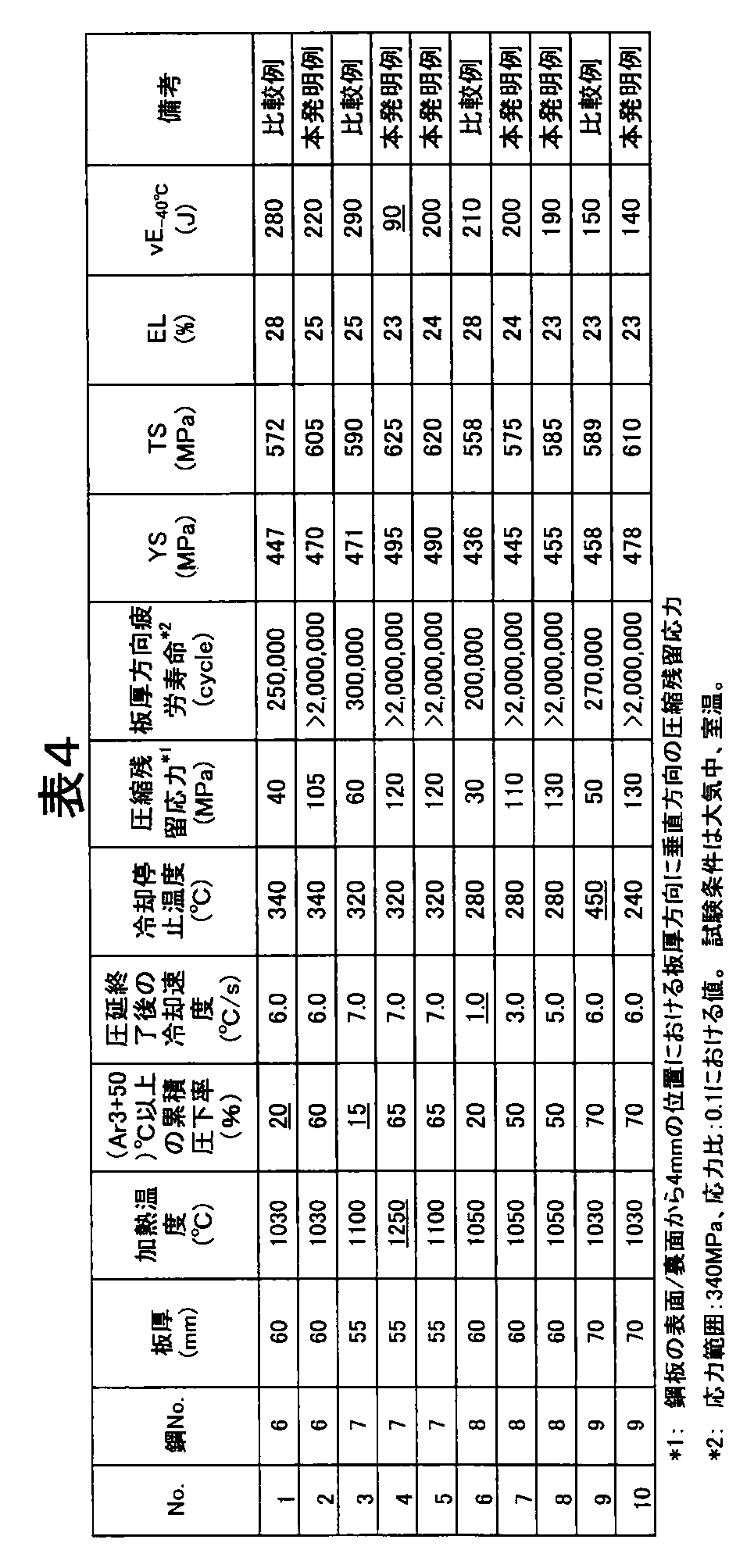
表3に化学成分、表4に製造条件および特性を示す板厚55~70mmの板厚方向の疲労特性に優れる厚鋼板2を用いて、隅肉溶接継手を作製し、図2に形状を示す切欠付3点曲げ隅肉溶接継手疲労試験片を用いて3点曲げ疲労試験を実施した。厚鋼板2の組織、機械的特性および板厚方向疲労特性を確認するための試験方法は、実施例1と同様に行った。
上述した試験により特性を確認した厚鋼板2を用いて、図4に示す条件にて隅肉溶接継手を作製し、疲労試験を実施した。疲労試験片として、図2に示す寸法形状の切欠付3点曲げ隅肉溶接継手疲労試験片を用い、応力範囲が340MPa、応力比R(=最小荷重/最大荷重)が0.1となる条件で実施して、疲労寿命を求めた。厚鋼板2で得られた結果を表5に示す。
厚鋼板2において、本発明例(試験No.2、7、8、10)はいずれも、応力範囲340MPaの厳しい条件で、疲労寿命が25万回以上で耐疲労特性に優れた隅肉溶接継手の得られることが確認された。一方、本発明で規定する溶接条件(入熱30kJ/cm以下、3層以下かつ6パス以下の積層条件)の範囲を外れる比較例(試験No.4、5)および、板厚方向の疲労寿命が劣る厚鋼板を用いた比較例(試験No.1、3、6、9)は、耐疲労特性が確保できていない。



Claims (7)
- 鋼板の圧延面の両側または片側から板厚方向に4mmまでの範囲において、板厚方向に直角となる圧縮残留応力が100MPa以上である厚鋼板。
- 前記厚鋼板が、質量%で、C:0.03~0.15%、Si:1.0%以下、Mn:1.0~2.0%を含み、更にTi:0.005~0.05%、Nb:0.001~0.05%の1種または2種、N:0.0035~0.0075%を含有し、残部Feおよび不可避的不純物からなる組成を有する請求項1に記載の厚鋼板。
- 更に、質量%で、Cu:0.01~0.5%、Ni:2.0%以下、Cr:0.01~0.5%、Mo:0.01~0.5%、V:0.001~0.1%、W:0.5%以下、Zr:0.5%以下、Ca:0.0005~0.0030%、B:0.0005~0.0020%の1種または2種以上を含有する組成とする請求項2に記載の厚鋼板。
- 更に、質量%で、Al:0.1%以下を含有する組成とする請求項2または3に記載の厚鋼板。
- 請求項2ないし4のいずれか一つに記載の化学成分を有する鋼素材を、1000~1250℃の温度に加熱後、板厚中央部が(Ar3 点+50)℃以上となる温度域で累積圧下率30%以上の熱間圧延を行い、その後、3℃/s以上の冷却速度にて350℃以下まで冷却する厚鋼板の製造方法。
- 板厚50mm以上の板厚方向の耐疲労特性に優れた厚鋼板の隅肉部を、入熱30kJ/cm以下、3層以下かつ6パス以下の積層で溶接した隅肉溶接継手。
- 前記板厚50mm以上の厚鋼板の圧延面の両側または片側から板厚方向に4mmまでの範囲において、板厚方向と直角方向の圧縮残留応力が100MPa以上である請求項6に記載の隅肉溶接継手。
Priority Applications (3)
| Application Number | Priority Date | Filing Date | Title |
|---|---|---|---|
| CN201280015840.4A CN103459637B (zh) | 2011-03-28 | 2012-03-27 | 板厚方向的抗疲劳特性优异的厚钢板及其制造方法和使用该厚钢板的角焊接头 |
| KR1020167003625A KR101687687B1 (ko) | 2011-03-28 | 2012-03-27 | 판두께 방향의 내피로 특성이 우수한 후강판 및 그의 제조 방법, 그 후강판을 이용한 필렛 용접 조인트 |
| KR1020137024879A KR20130125822A (ko) | 2011-03-28 | 2012-03-27 | 판두께 방향의 내피로 특성이 우수한 후강판 및 그의 제조 방법, 그 후강판을 이용한 필렛 용접 조인트 |
Applications Claiming Priority (6)
| Application Number | Priority Date | Filing Date | Title |
|---|---|---|---|
| JP2011-069728 | 2011-03-28 | ||
| JP2011069728 | 2011-03-28 | ||
| JP2011069729A JP5884150B2 (ja) | 2011-03-28 | 2011-03-28 | 隅肉溶接継手の製造方法 |
| JP2011-069729 | 2011-03-28 | ||
| JP2012066668A JP5949023B2 (ja) | 2011-03-28 | 2012-03-23 | 板厚方向の耐疲労特性に優れた厚鋼板およびその製造方法 |
| JP2012-066668 | 2012-03-23 |
Publications (1)
| Publication Number | Publication Date |
|---|---|
| WO2012133879A1 true WO2012133879A1 (ja) | 2012-10-04 |
Family
ID=46931566
Family Applications (1)
| Application Number | Title | Priority Date | Filing Date |
|---|---|---|---|
| PCT/JP2012/058787 Ceased WO2012133879A1 (ja) | 2011-03-28 | 2012-03-27 | 板厚方向の耐疲労特性に優れた厚鋼板およびその製造方法、その厚鋼板を用いた隅肉溶接継手 |
Country Status (1)
| Country | Link |
|---|---|
| WO (1) | WO2012133879A1 (ja) |
Citations (3)
| Publication number | Priority date | Publication date | Assignee | Title |
|---|---|---|---|---|
| JPH08253821A (ja) * | 1995-03-16 | 1996-10-01 | Nippon Steel Corp | 優れた疲労強度を有する溶接継手の製造方法 |
| WO2006009299A1 (ja) * | 2004-07-21 | 2006-01-26 | Nippon Steel Corporation | 溶接熱影響部の低温靭性が優れた溶接構造用鋼およびその製造方法 |
| JP2007046096A (ja) * | 2005-08-09 | 2007-02-22 | Nippon Steel Corp | 靭性に優れた厚手高強度鋼板の製造方法及び靭性に優れた厚手高強度鋼板 |
-
2012
- 2012-03-27 WO PCT/JP2012/058787 patent/WO2012133879A1/ja not_active Ceased
Patent Citations (3)
| Publication number | Priority date | Publication date | Assignee | Title |
|---|---|---|---|---|
| JPH08253821A (ja) * | 1995-03-16 | 1996-10-01 | Nippon Steel Corp | 優れた疲労強度を有する溶接継手の製造方法 |
| WO2006009299A1 (ja) * | 2004-07-21 | 2006-01-26 | Nippon Steel Corporation | 溶接熱影響部の低温靭性が優れた溶接構造用鋼およびその製造方法 |
| JP2007046096A (ja) * | 2005-08-09 | 2007-02-22 | Nippon Steel Corp | 靭性に優れた厚手高強度鋼板の製造方法及び靭性に優れた厚手高強度鋼板 |
Similar Documents
| Publication | Publication Date | Title |
|---|---|---|
| US11628512B2 (en) | Clad steel plate and method of producing the same | |
| RU2550985C2 (ru) | Стойкая к истиранию толстолистовая сталь, которая демонстрирует превосходную ударную вязкость сварного шва и превосходную стойкость к замедленному разрушению | |
| JP5817832B2 (ja) | 溶接熱影響部の低温靭性に優れた高張力鋼板およびその製造方法 | |
| JP5096088B2 (ja) | 靭性および疲労亀裂発生抑制特性に優れた溶接継手 | |
| JP6555435B2 (ja) | クラッド鋼板およびその製造方法 | |
| JP4484123B2 (ja) | 高強度かつ溶接熱影響部靭性に優れたクラッド鋼板用母材およびその製造方法 | |
| WO2012002563A1 (ja) | 溶接部靭性と耐遅れ破壊特性に優れた耐磨耗鋼板 | |
| WO2013114851A1 (ja) | 溶接部靭性に優れた高靭性クラッド鋼板の母材及びそのクラッド鋼板の製造方法 | |
| JPWO2010038470A1 (ja) | 母材および溶接熱影響部の低温靭性に優れかつ強度異方性の小さい鋼板およびその製造方法 | |
| JP5668668B2 (ja) | 溶接熱影響部の靭性に優れた鋼材並びに溶接継手、溶接継手の製造方法 | |
| KR101594913B1 (ko) | 판두께 방향의 내피로 특성이 우수한 후강판 및 그의 제조 방법, 그 후강판을 이용한 필렛 용접 조인트 | |
| JP2006118007A (ja) | 溶接熱影響部の靭性に優れた高強度鋼材 | |
| JP4924047B2 (ja) | 表面残留応力の絶対値が150N/mm2以下の耐疲労亀裂伝播特性に優れた鋼材の製造方法 | |
| JP7586383B1 (ja) | クラッド鋼板の製造方法 | |
| KR101687687B1 (ko) | 판두께 방향의 내피로 특성이 우수한 후강판 및 그의 제조 방법, 그 후강판을 이용한 필렛 용접 조인트 | |
| JP5170212B2 (ja) | 高い降伏点を有する高張力鋼材の製造方法 | |
| JP5949023B2 (ja) | 板厚方向の耐疲労特性に優れた厚鋼板およびその製造方法 | |
| JP5151510B2 (ja) | 低温靭性、亀裂伝搬停止特性に優れた高張力鋼の製造方法 | |
| WO2012133872A1 (ja) | 板厚方向の耐疲労特性に優れた厚鋼板およびその製造方法、その厚鋼板を用いた隅肉溶接継手 | |
| JP5884150B2 (ja) | 隅肉溶接継手の製造方法 | |
| JP5906868B2 (ja) | 板厚方向の耐疲労特性に優れた厚鋼板およびその製造方法 | |
| JPH06271984A (ja) | 耐疲労伝播特性とアレスト性の優れた鋼板およびその製造方法 | |
| WO2025192475A1 (ja) | クラッド鋼板、溶接継手およびそれらの製造方法 | |
| JP2012177192A (ja) | 引張強さ(TS)が780MPa以上の大入熱溶接熱影響部の靭性と小入熱溶接熱影響部の耐硬化特性に優れた高強度厚鋼板およびその製造方法 |
Legal Events
| Date | Code | Title | Description |
|---|---|---|---|
| 121 | Ep: the epo has been informed by wipo that ep was designated in this application |
Ref document number: 12765555 Country of ref document: EP Kind code of ref document: A1 |
|
| ENP | Entry into the national phase |
Ref document number: 20137024879 Country of ref document: KR Kind code of ref document: A |
|
| NENP | Non-entry into the national phase |
Ref country code: DE |
|
| 122 | Ep: pct application non-entry in european phase |
Ref document number: 12765555 Country of ref document: EP Kind code of ref document: A1 |