WO2012133751A1 - バーナ、これを備えたガス化炉等の反応炉およびこれを備えた発電プラント - Google Patents
バーナ、これを備えたガス化炉等の反応炉およびこれを備えた発電プラント Download PDFInfo
- Publication number
- WO2012133751A1 WO2012133751A1 PCT/JP2012/058544 JP2012058544W WO2012133751A1 WO 2012133751 A1 WO2012133751 A1 WO 2012133751A1 JP 2012058544 W JP2012058544 W JP 2012058544W WO 2012133751 A1 WO2012133751 A1 WO 2012133751A1
- Authority
- WO
- WIPO (PCT)
- Prior art keywords
- pipe
- burner
- oxidant
- oxidizing agent
- fuel
- Prior art date
- Legal status (The legal status is an assumption and is not a legal conclusion. Google has not performed a legal analysis and makes no representation as to the accuracy of the status listed.)
- Ceased
Links
Images



Classifications
-
- F—MECHANICAL ENGINEERING; LIGHTING; HEATING; WEAPONS; BLASTING
- F23—COMBUSTION APPARATUS; COMBUSTION PROCESSES
- F23D—BURNERS
- F23D1/00—Burners for combustion of pulverulent fuel
-
- C—CHEMISTRY; METALLURGY
- C10—PETROLEUM, GAS OR COKE INDUSTRIES; TECHNICAL GASES CONTAINING CARBON MONOXIDE; FUELS; LUBRICANTS; PEAT
- C10J—PRODUCTION OF PRODUCER GAS, WATER-GAS, SYNTHESIS GAS FROM SOLID CARBONACEOUS MATERIAL, OR MIXTURES CONTAINING THESE GASES; CARBURETTING AIR OR OTHER GASES
- C10J3/00—Production of combustible gases containing carbon monoxide from solid carbonaceous fuels
- C10J3/46—Gasification of granular or pulverulent flues in suspension
- C10J3/48—Apparatus; Plants
- C10J3/485—Entrained flow gasifiers
-
- C—CHEMISTRY; METALLURGY
- C10—PETROLEUM, GAS OR COKE INDUSTRIES; TECHNICAL GASES CONTAINING CARBON MONOXIDE; FUELS; LUBRICANTS; PEAT
- C10J—PRODUCTION OF PRODUCER GAS, WATER-GAS, SYNTHESIS GAS FROM SOLID CARBONACEOUS MATERIAL, OR MIXTURES CONTAINING THESE GASES; CARBURETTING AIR OR OTHER GASES
- C10J3/00—Production of combustible gases containing carbon monoxide from solid carbonaceous fuels
- C10J3/46—Gasification of granular or pulverulent flues in suspension
- C10J3/48—Apparatus; Plants
- C10J3/50—Fuel charging devices
- C10J3/506—Fuel charging devices for entrained flow gasifiers
-
- F—MECHANICAL ENGINEERING; LIGHTING; HEATING; WEAPONS; BLASTING
- F23—COMBUSTION APPARATUS; COMBUSTION PROCESSES
- F23C—METHODS OR APPARATUS FOR COMBUSTION USING FLUID FUEL OR SOLID FUEL SUSPENDED IN A CARRIER GAS OR AIR
- F23C5/00—Disposition of burners with respect to the combustion chamber or to one another; Mounting of burners in combustion apparatus
- F23C5/02—Structural details of mounting
-
- F—MECHANICAL ENGINEERING; LIGHTING; HEATING; WEAPONS; BLASTING
- F23—COMBUSTION APPARATUS; COMBUSTION PROCESSES
- F23L—SUPPLYING AIR OR NON-COMBUSTIBLE LIQUIDS OR GASES TO COMBUSTION APPARATUS IN GENERAL ; VALVES OR DAMPERS SPECIALLY ADAPTED FOR CONTROLLING AIR SUPPLY OR DRAUGHT IN COMBUSTION APPARATUS; INDUCING DRAUGHT IN COMBUSTION APPARATUS; TOPS FOR CHIMNEYS OR VENTILATING SHAFTS; TERMINALS FOR FLUES
- F23L7/00—Supplying non-combustible liquids or gases, other than air, to the fire, e.g. oxygen, steam
-
- C—CHEMISTRY; METALLURGY
- C10—PETROLEUM, GAS OR COKE INDUSTRIES; TECHNICAL GASES CONTAINING CARBON MONOXIDE; FUELS; LUBRICANTS; PEAT
- C10J—PRODUCTION OF PRODUCER GAS, WATER-GAS, SYNTHESIS GAS FROM SOLID CARBONACEOUS MATERIAL, OR MIXTURES CONTAINING THESE GASES; CARBURETTING AIR OR OTHER GASES
- C10J2300/00—Details of gasification processes
- C10J2300/09—Details of the feed, e.g. feeding of spent catalyst, inert gas or halogens
- C10J2300/0913—Carbonaceous raw material
- C10J2300/093—Coal
-
- C—CHEMISTRY; METALLURGY
- C10—PETROLEUM, GAS OR COKE INDUSTRIES; TECHNICAL GASES CONTAINING CARBON MONOXIDE; FUELS; LUBRICANTS; PEAT
- C10J—PRODUCTION OF PRODUCER GAS, WATER-GAS, SYNTHESIS GAS FROM SOLID CARBONACEOUS MATERIAL, OR MIXTURES CONTAINING THESE GASES; CARBURETTING AIR OR OTHER GASES
- C10J2300/00—Details of gasification processes
- C10J2300/16—Integration of gasification processes with another plant or parts within the plant
- C10J2300/164—Integration of gasification processes with another plant or parts within the plant with conversion of synthesis gas
- C10J2300/1643—Conversion of synthesis gas to energy
- C10J2300/1653—Conversion of synthesis gas to energy integrated in a gasification combined cycle [IGCC]
-
- F—MECHANICAL ENGINEERING; LIGHTING; HEATING; WEAPONS; BLASTING
- F23—COMBUSTION APPARATUS; COMBUSTION PROCESSES
- F23D—BURNERS
- F23D2211/00—Thermal dilatation prevention or compensation
-
- F—MECHANICAL ENGINEERING; LIGHTING; HEATING; WEAPONS; BLASTING
- F23—COMBUSTION APPARATUS; COMBUSTION PROCESSES
- F23L—SUPPLYING AIR OR NON-COMBUSTIBLE LIQUIDS OR GASES TO COMBUSTION APPARATUS IN GENERAL ; VALVES OR DAMPERS SPECIALLY ADAPTED FOR CONTROLLING AIR SUPPLY OR DRAUGHT IN COMBUSTION APPARATUS; INDUCING DRAUGHT IN COMBUSTION APPARATUS; TOPS FOR CHIMNEYS OR VENTILATING SHAFTS; TERMINALS FOR FLUES
- F23L2900/00—Special arrangements for supplying or treating air or oxidant for combustion; Injecting inert gas, water or steam into the combustion chamber
- F23L2900/07002—Injecting inert gas, other than steam or evaporated water, into the combustion chambers
-
- Y—GENERAL TAGGING OF NEW TECHNOLOGICAL DEVELOPMENTS; GENERAL TAGGING OF CROSS-SECTIONAL TECHNOLOGIES SPANNING OVER SEVERAL SECTIONS OF THE IPC; TECHNICAL SUBJECTS COVERED BY FORMER USPC CROSS-REFERENCE ART COLLECTIONS [XRACs] AND DIGESTS
- Y02—TECHNOLOGIES OR APPLICATIONS FOR MITIGATION OR ADAPTATION AGAINST CLIMATE CHANGE
- Y02E—REDUCTION OF GREENHOUSE GAS [GHG] EMISSIONS, RELATED TO ENERGY GENERATION, TRANSMISSION OR DISTRIBUTION
- Y02E20/00—Combustion technologies with mitigation potential
- Y02E20/16—Combined cycle power plant [CCPP], or combined cycle gas turbine [CCGT]
-
- Y—GENERAL TAGGING OF NEW TECHNOLOGICAL DEVELOPMENTS; GENERAL TAGGING OF CROSS-SECTIONAL TECHNOLOGIES SPANNING OVER SEVERAL SECTIONS OF THE IPC; TECHNICAL SUBJECTS COVERED BY FORMER USPC CROSS-REFERENCE ART COLLECTIONS [XRACs] AND DIGESTS
- Y02—TECHNOLOGIES OR APPLICATIONS FOR MITIGATION OR ADAPTATION AGAINST CLIMATE CHANGE
- Y02E—REDUCTION OF GREENHOUSE GAS [GHG] EMISSIONS, RELATED TO ENERGY GENERATION, TRANSMISSION OR DISTRIBUTION
- Y02E20/00—Combustion technologies with mitigation potential
- Y02E20/16—Combined cycle power plant [CCPP], or combined cycle gas turbine [CCGT]
- Y02E20/18—Integrated gasification combined cycle [IGCC], e.g. combined with carbon capture and storage [CCS]
-
- Y—GENERAL TAGGING OF NEW TECHNOLOGICAL DEVELOPMENTS; GENERAL TAGGING OF CROSS-SECTIONAL TECHNOLOGIES SPANNING OVER SEVERAL SECTIONS OF THE IPC; TECHNICAL SUBJECTS COVERED BY FORMER USPC CROSS-REFERENCE ART COLLECTIONS [XRACs] AND DIGESTS
- Y10—TECHNICAL SUBJECTS COVERED BY FORMER USPC
- Y10T—TECHNICAL SUBJECTS COVERED BY FORMER US CLASSIFICATION
- Y10T29/00—Metal working
- Y10T29/49—Method of mechanical manufacture
- Y10T29/49348—Burner, torch or metallurgical lance making
Definitions
- the present invention relates to a burner, a reaction furnace such as a gasification furnace provided with the same, and a power plant equipped with the same, and more particularly to a burner installed in the reaction furnace such as a gasification furnace.
- a reactor such as a gasification furnace provided in the power generation plant has a pressure vessel 11 and a reactor body 12 provided in the pressure vessel 11, as shown in FIG. 2 and FIG.
- a space 13 called an annulus is provided between the vessel 11 and the reactor body 12 to maintain a high pressure state in the reactor 10.
- the burner 20 has a base end on the side wall of the reaction furnace main body 12, extends from the side wall of the reaction furnace main body 12 toward the pressure vessel 11 and penetrates the pressure vessel 11. Is provided.
- the burner 20 covers a fuel pipe 22 to which fuel such as pulverized coal is introduced by nitrogen as a carrier gas, and the outer periphery of the fuel pipe 22, and an oxidant such as air is oxidized between the fuel pipe 22 and the outer periphery thereof.
- both the reactor body 12 and the pressure vessel 11 produce thermal expansion. Therefore, a thermal elongation difference occurs between the reaction furnace main body 12 and the pressure vessel 11 due to the difference in temperature and material. Thereby, as shown in FIG. 4, the burner 20 is bent.
- the overall length of the oxidizing agent pipe 23 is lengthened to reduce the angular displacement.
- fixed part of both ends by doing is below an allowance is used. Therefore, the length of the burner 20 (the length indicated by A in FIG. 2) is a length corresponding to the stress generated in the oxidizing agent pipe 23 (the burner selection length in FIG. 2).
- the length of the burner 20 is determined to a length corresponding to the stress generated in the fixed portion of the oxidant pipe 23, the weight of the burner 20 increases and maintenance is performed when the burner 20 is pulled out for maintenance. There is a problem of deterioration and, in addition, the arrangement of equipment and piping around the burner 20 is limited.
- the seal packing is provided with a gland packing 31 in the sleeve 32.
- the sleeve 32, ie, the reaction furnace 12 side, and the oxidant pipe 3 are structured such that relative movement in the axial direction is permitted via the gland packing 31 (for example, Patent Documents 3 and 4).
- the oxidizing agent pipe 3 extends so as to protrude into the reaction furnace 12, and the combustion position of the burner is largely changed. There is a problem that stable combustion can not be performed.
- the present invention has been made in view of such circumstances, and the weight reduction and maintenance performance due to the reduction of the burner length, the improvement of the peripheral device arrangement, and the combustion position even if the burner is thermally elongated It is an object of the present invention to provide a burner which can perform stable combustion with almost no change, a reactor such as a gasification furnace equipped with the same, and a power plant equipped with the same.
- the burner of the present invention adopts the following means. That is, according to the burner of the present invention, a fuel pipe and an oxidant pipe which is concentric with the fuel pipe and covers the outer periphery of the fuel pipe and into which the oxidant is introduced between the fuel pipe and the side wall of the fuel pipe And a protective cylinder covering the outer periphery of the oxidizing agent pipe, and a displacement absorbing member provided on at least a part of the extending direction of the protective cylinder and the oxidizing agent pipe, The pipe, the oxidant pipe and the protective cylinder are fixed to the side wall of the inner vessel of the gasification furnace in which the non-oxidizing gas is filled between the inner vessel and the outer vessel covering the inner vessel at the base end thereof.
- the overall length being determined in response to the stresses in the fuel tube, the oxidizer tube being the oxidant
- the length at which the pipe and the tip of the fuel pipe project into the gasification furnace does not change As, characterized in that it is positioned with respect to the side wall of the inner container.
- the displacement absorbing member of the present invention also for the oxidizer tube of the burner, at least a part of the extending direction of the oxidizer tube of the burner whose base end is fixed to the side wall of the inner vessel of the gasification furnace Provided a displacement absorbing member.
- the burner bends and the bending stress generated in the oxidizing agent pipe or the fuel pipe is generated in the oxidizing agent pipe Bending stress can be absorbed by the displacement absorbing member.
- the burner length can be determined by the length of the fuel pipe according to the stress generated in the fuel pipe.
- the bending stress generated is smaller compared to other tubes.
- the burner length can be shortened compared to the conventional case where the burner length is determined based on the bending stress generated in the oxidant pipe which is a pipe diameter larger than the fuel pipe. Therefore, the weight of the burner can be reduced and the maintainability can be improved.
- the displacement absorbing member a bendable flexible pipe, a bellows that expands and contracts in the extending direction of the oxidizing agent pipe, and the like are used.
- the oxidizer tube is positioned relative to the sidewall of the inner container so that the length of the tip of the oxidizer tube projecting into the reactor does not change.
- the thermal expansion in the axial direction of the oxidizing agent tube which occurs between the positioning portion (fixing portion) of the inner side wall and the furnace outer fixing portion, is absorbed by the above-mentioned displacement absorbing member. Since the length from the positioning portion (fixing portion) of the inner side wall to the furnace inner end of the oxidant pipe is small, the thermal expansion amount in the furnace inner axial direction of this portion is extremely small and negligible in combustion. As a result, the influence of the thermal expansion of the oxidant pipe is eliminated, and the burner can be stably burned at a predetermined position.
- the effect of corrosion by the generated gas can be avoided by filling the non-oxidizing gas between the inner container and the outer container of the reactor comprising the inner container and the outer container. Since it is possible to use a displacement absorbing member such as a flexible pipe which is a thin-walled member and easily broken by corrosion for the oxidizing agent pipe of the burner, the burner of which the base end is fixed to the side wall of the inner vessel of the gasification furnace A displacement absorbing member is provided in at least a part of the extending direction of the oxidizing agent pipe.
- the burner length is determined by the length of the fuel pipe according to the stress generated in the fuel pipe.
- the fuel pipe having the smallest pipe diameter among the pipe and the protective cylinder constituting the burner is compared at the same length and bending amount, the bending stress generated is smaller compared to the other pipes. In other words, when the generated stress is allowed to be equal, the same amount of bending can be handled with a shorter length than other pipes having a large pipe diameter.
- the burner length can be shortened compared to the conventional case where the burner length is determined based on the bending stress generated in the oxidant pipe which is a pipe diameter larger than the fuel pipe. Therefore, the weight of the burner can be reduced and the maintainability can be improved.
- the oxidant pipe is positioned with respect to the side wall of the inner container, and the thermal expansion in the axial direction of the oxidant pipe between the positioning portion (fixing portion) of the inner side wall and the furnace outer fixing portion is the same as described above. Absorb by the displacement absorbing member. Since the length from the positioning portion (fixing portion) of the inner side wall to the furnace inner end of the oxidant pipe is small, the thermal expansion amount in the furnace inner axial direction of this portion is extremely small and negligible in combustion. As a result, the influence of the thermal expansion of the oxidant pipe is eliminated, and the burner can be stably burned at a predetermined position.
- FIG. 1 An integrated coal gasification combined cycle (IGCC) fueled by a carbon-containing fuel (for example, coal etc.) mainly comprises a coal gasification furnace (reactor) 10 and a gas turbine (not shown). , An exhaust heat recovery boiler (not shown), and a steam turbine (not shown).
- IGCC integrated coal gasification combined cycle
- a coal supply facility for supplying pulverized coal to the coal gasifier 10 is provided.
- This coal supply facility is equipped with a crusher (not shown) that crushes raw material coal into pulverized coal of several ⁇ m to several hundreds of ⁇ m, and the pulverized coal pulverized by this crusher has a constant flow rate of nitrogen etc.
- a crusher not shown
- the coal gasification furnace 10 is called an annulus between a reaction furnace (inner vessel) 12 which is a water-cooled wall, a pressure vessel (outer vessel) 11 covering the reaction furnace 12, and the reactor 12 and the pressure vessel 11.
- a space portion 13 is provided.
- the space 13 is filled with a nonoxidizing gas such as nitrogen gas, for example.
- the burner 1 is fixed to the side wall of the reaction furnace 12 of such a coal gasifier 10 so as to be orthogonal to the side wall.
- the burner 1 is fixed to a reactor side opening 12 a opened in a side wall of the reactor 12 via a seal box 15.
- the seal box 15 is made of, for example, SUS and a refractory material, and the burner 1 penetrates a substantially central portion thereof.
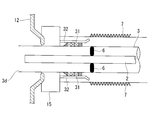
- the oxidant pipe 3 is positioned relative to the reactor 12 by the fixing portion 30.
- the fixing portion 30 includes a sleeve 30a and an oxidant pipe flange portion 30b.
- the proximal end of the sleeve 30a is joined and fixed to the seal box 15 side. That is, the sleeve 30a is fixed to the inner container 12 side.
- the oxidizing agent pipe flange part 30b which had disk shape was provided in the oxidizing agent pipe 3 by the side of the outer side container 11 (right side in the figure).
- the sleeve 30a and the oxidant pipe flange portion 30b can be connected in a state where they are butted.
- the fixing portion 30 is fastened and fixed by a fixing tool 30c such as a bolt.
- the oxidant pipe 3 is provided with an expansion 7 for an oxidant pipe.
- the pressure vessel side opening 11a is a flange, and is fixed by a support cylinder 16 capable of supporting the burner 1 to the pressure vessel side opening 11a, which is a flange, and a bolt (not shown). Both ends of the support cylinder 16 are flange portions 16a and 16b.
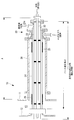
- the burner 1 is substantially concentric with the fuel pipe 2 and the fuel pipe 2, and is substantially concentric with the oxidant pipe 3 covering the outer periphery of the fuel pipe 2, with the fuel pipe 2 and the oxidant pipe 3. And a guide tube (protective tube) 4 covering the outer periphery of
- the fuel pipe 2 is a tube into which pulverized fuel such as pulverized coal transported by nitrogen or the like is introduced.
- the fuel pipe 2 extends through the seal box 15 into the reactor body 12 at one end thereof as shown in FIG. Further, the other end of the fuel pipe 2 is connected to a pulverized fuel transport pipe (not shown) for transporting fuel such as pulverized coal from a pulverizer.
- the fuel pipe 2 is a stress generated in the fuel pipe 2, for example, a penetration portion (not shown) of the fuel pipe 2 penetrating the seal box 15, and a penetration of the fuel pipe 2 penetrating a flange portion 3a described later.
- the length in the extension direction (the burner selection length in FIG. 1) is determined in accordance with the stress generated in the portion (not shown). Therefore, the length in the extension direction of the fuel pipe 2 is substantially equal to the length (length) of the burner 1.
- the fuel pipe 2 has a plurality of supports 6 extending outward from its outer wall.
- a plurality of supports 6 are provided radially in the circumferential direction of the fuel pipe 2 and at different positions in the axial direction of the fuel pipe 2.
- the extending end of the radially extending support 6 is in the vicinity of the inner wall of the oxidizing agent pipe 3 and is not fixed to the inner wall of the oxidizing agent pipe 3.
- the oxidant pipe 3 covers the outer periphery of the fuel pipe 2 and has a larger outside dimension than the fuel pipe 2.
- An oxidizing agent introducing flange portion 3 c is provided on the side wall of the oxidizing agent pipe 3.
- air which is an oxidizing agent, is introduced between the inner wall and the outer wall of the fuel pipe 2 from the oxidizing agent introducing flange portion 3c.
- the oxidizing agent pipe 3 extends through the seal box 15 into the reactor 12 as shown in FIG. 1 at one end thereof. Further, a flange portion 3 a is provided in the vicinity of the end opposite to the end connected to the seal box 15 of the oxidant pipe 3. Furthermore, the oxidizing agent pipe 3 is provided with a flange portion 3b on the side of the coal gasifier 10 rather than the flange portion 3a, and can be connected to the flange portion 4a provided on a guide cylinder 4 described later. .
- the oxidant pipe expansion (displacement absorbing member) in a part (at least a part in the extension direction, two places in FIG. 1) in the axial direction exposed in the support cylinder 16 and the space 13 in the oxidant pipe 3 ) 7 is provided.
- the oxidant pipe expansion 7 is a pipe which can be bent and axially expanded and contracted.
- the guide cylinder 4 covers the outer circumferences of the combustion pipe 2 and the oxidant pipe 3 and has a larger outside dimension than the oxidant pipe 3.
- the guide cylinder 4 has an oxidant pipe 3 and a fuel pipe 2 inside.
- a non-oxidizing gas is introduced into the space (not shown) between the inner wall of the guide cylinder 4 and the outer wall of the oxidizing agent pipe 3 on the outer wall between the flange portion 4a and the flange portion 4b of the guide cylinder 4
- a nonoxidizing gas introduction pipe and a flange portion 4c are provided.
- the non-oxidizing gas introduced from the flange 4c is, for example, nitrogen gas.
- the guide cylinder 4 is supported at one end by the seal box 15 and at the other end by the flange 4 b.
- the guide cylinder 4 is provided at its end opposite to one end fixed to the seal box 15 with a flange portion 4a connected to the flange portion 3b provided on the aforementioned oxidizing agent pipe 3. Further, a flange portion 4 b is provided on the guide cylinder 4 closer to the coal gasifier 10 than the flange portion 4 a, and can be connected to the flange portion 16 b of the support cylinder 16.
- the guide cylinder 4 has a function of blocking the space 13 and the space around the oxidizing agent pipe 3 and protecting the oxidizing agent pipe 3 from generated gas, char and the like that may partially flow in in rare cases.
- a nonoxidizing gas for example, nitrogen
- a nonoxidizing gas introduction pipe and the flange portion 4c to maintain a nitrogen atmosphere. It has become.
- the guide cylinder 4 is provided with the guide cylinder expansion 5 in a part (two places in FIG. 1) in the axial direction exposed to the inside of the support cylinder 16 and the space 13.
- the guide cylinder expansion 5 is a pipe capable of bending and axial expansion and contraction in the same manner as the oxidant pipe expansion 7.
- the state of the stress applied to the burner 1 due to the operation of the power generation plant will be described with reference to FIG.
- thermal expansion occurs in the reactor body 12 and the pressure vessel 11 of the coal gasifier (reactor) 10.
- the thermal elongation generated in the reaction furnace main body 12 and the pressure vessel 11 causes a difference (thermal elongation difference) due to the difference in the material and temperature between the reaction furnace main body 12 and the pressure vessel 11. Therefore, the burner 1 inserted into the reaction furnace main body 12 from the outside of the pressure vessel 11 is, for example, the side fixed to the reaction furnace main body 12 via the seal box 15 (hereinafter referred to as “base end” ) Is displaced downward with the start of operation.
- the oxidant pipe expansion 7 is also provided in the oxidant pipe 3, when the proximal end of the burner 1 tries to be displaced downward. In this case, the oxidant pipe expansion 7 is bent downward. As a result, it is possible to relieve the bending stress generated in the base end portion of the oxidizing agent pipe 3, the flange portion 3 b of the oxidizing agent pipe 3, and the fixing portion of the oxidizing agent pipe 3.
- the bending stress generated in the oxidizing agent pipe 3 is relieved by the oxidizing agent pipe expansion 7, but the bending stress is generated in the fuel pipe 2 by the downward displacement of the burner 1.
- the fuel pipe 2 has a smaller pipe diameter than the oxidant pipe 3 and the guide cylinder 4 constituting the burner 1 and the same length and bending amount are compared, bending occurs as compared with other pipes. Stress is small.
- the length of the burner 1 (the length indicated by A in FIG. 1) can be determined according to the burner selection length of the fuel pipe 2 determined according to the bending stress generated in the fuel pipe 2, and the oxidant pipe The burner length can be made shorter than in the case of 3 selected.
- the space 13 of the coal gasification furnace (reactor) 10 is filled with the non-oxidizing gas introduced from the non-oxidizing gas introduction pipe 4c, it partially flows from the inside of the reaction furnace main body 12 Ingress of corrosive product gas is prevented. Therefore, there is no possibility that the oxidant pipe 3 and the oxidant pipe expansion 7 are corroded by the corrosive product gas.
- the oxidant pipe 3 is positioned by the fixing portion 30 with respect to the reactor body 12. This positioning is performed so that the length at which the burner tip 3d of the oxidant pipe 3 and the fuel pipe 2 protrudes into the reactor does not change, and the positioning part 30 (fixed part) of the inner side wall and the furnace outside
- the thermal expansion in the axial direction of the oxidizing agent pipe 3 generated between the fixing portions is absorbed by the aforementioned expansion 7 for an oxidizing agent pipe. Since the length from the positioning part 30 (fixed part) of the inner side wall to the furnace inner end of the oxidizing agent pipe 3 is small, the thermal expansion amount in the furnace inner axial direction of this part is extremely small and negligible in combustion. .
- coal gasification furnace (reactor) 10 provided with this, and a power plant provided with this, the following operation effects are produced.
- reaction furnace reaction furnace
- the reactor body (inner vessel) 12 and the pressure vessel (outer vessel) 11 Extension of the oxidizing agent pipe 3 of the burner 1 which is filled with nitrogen gas which is a non-oxidizing gas and whose base end is fixed to the side wall of the reactor main body 12 of the coal gasifier (reactor) 10
- An oxidant pipe expansion (displacement absorbing member) 7 is provided in part (at least part) of the direction.
- the burner 1 is bent and bending stress generated in the oxidant pipe 3 and the fuel pipe 2
- the bending stress generated in the oxidant pipe 3 can be absorbed by the expansion 7 for an oxidant pipe.
- the length of the burner 1 (the length indicated by A in FIG. 1) is determined by the burner selection length of the fuel pipe 2 which is determined according to the bending stress generated in the fuel pipe 2.
- the fuel pipe 2 constituting the burner 1 the oxidant pipe 3 and the guide cylinder (protective pipe) 4
- the fuel pipe 2 having the smallest pipe diameter generates a small bending stress.
- the length of the burner 1 is determined based on the bending stress generated in the oxidant pipe 3 which is a pipe diameter larger than the fuel pipe 2. Therefore, the weight of the burner 1 can be reduced and the maintainability can be improved.
- coal gasifier (reactor) 10 capable of reducing the space around the burner 1. Therefore, the space of the power plant can be reduced.
- the thermal expansion in the axial direction of the oxidizing agent tube 3 generated between the positioning portion 30 (fixed portion) of the inner side wall and the furnace outer fixed portion is fixed by the positioning portion 30 of the inner side wall and oxidized. It absorbs by expansion 7 for an oxidizing agent pipe installed in agent pipe 3. Since the length from the positioning part 30 (fixed part) of the inner side wall to the furnace inner end of the oxidizing agent pipe 3 is small, the thermal expansion amount in the furnace inner axial direction of this part is extremely small and negligible in combustion. . As a result, the burner tip 3d of the oxidizing agent pipe 3 is prevented from being thermally expanded to a large extent and being changed in position.
- the oxidant pipe 3 is provided with an expansion 7 for an oxidant pipe. Thereby, the thermal expansion of the oxidizing agent pipe 3 on the side of the outer container 11 from the fixing portion 30 can be absorbed by the expansion 7 for an oxidizing agent pipe.
- the oxidant pipe expansion 7 and the guide cylinder expansion 5 are provided as the displacement absorbing member, the present invention is not limited to this, and the oxidant pipe 3 and the guide cylinder 4 are provided. It may be an expansion such as a bellows that can expand and contract in the extending direction.
- the pulverized fuel such as pulverized coal introduced into the fuel pipe 2 may be, for example, char, oil, gas or the like.
- burner 2 fuel pipe 3 oxidant pipe 3 d burner tip 4 guide cylinder (protection cylinder) 4c Inert gas introduction pipe and flange 7 Expansion for oxidant pipe (displacement absorber) 10 Coal gasifier (reactor) 11 Pressure vessel (outer vessel) 12 Reactor main body (inner container) 13 space (annular) part A burner length (full length)
Landscapes
- Engineering & Computer Science (AREA)
- Chemical & Material Sciences (AREA)
- Combustion & Propulsion (AREA)
- Mechanical Engineering (AREA)
- General Engineering & Computer Science (AREA)
- Oil, Petroleum & Natural Gas (AREA)
- Organic Chemistry (AREA)
- Combustion Of Fluid Fuel (AREA)
- Devices And Processes Conducted In The Presence Of Fluids And Solid Particles (AREA)
- Gasification And Melting Of Waste (AREA)
Abstract
Description
このため、酸化剤管3が高温の酸化剤が内部を流れることにより熱伸びを起こすと、反応炉12内に酸化剤管3が突出するように伸びてバーナの燃焼位置が大きく変化してしまい、安定した燃焼を行うことができないという問題があった。
すなわち、本発明に係るバーナによれば、燃料管と、該燃料管と略同心円状であり該燃料管の外周を覆い、該燃料管の側壁との間に酸化剤が導入される酸化剤管と、該酸化剤管の外周を覆う保護筒と、該保護筒および前記酸化剤管のそれぞれに対して、それらの延在方向の少なくとも一部に設けられる変位吸収部材と、を備え、前記燃料管、前記酸化剤管および前記保護筒は、それらの基端部が内側容器と該内側容器を覆う外側容器との間に非酸化性ガスが充満するガス化炉の前記内側容器の側壁に固定されて、該内側容器の側壁から外側に向かって前記外側容器を貫通して延在しており、全長が、前記燃料管に生じる応力に応じて決定され、前記酸化剤管は、該酸化剤管および前記燃料管の先端が前記ガス化炉内に突出する長さが変化しないように、前記内側容器の側壁に対して位置決めされていることを特徴とする。
以上により、バーナ長は、燃料管に生じる応力に応じた燃料管の長さによって決めることができる。ここで、バーナを構成する管および保護筒の中で管径が最小の燃料管は、同一の長さ・曲げ量で比較した場合、他管に比べて発生する曲げ応力が小さい。言い換えると、発生応力を同等まで許容する場合、管径が大きい他管よりも短い長さで同一の曲げ量に対応できる。そのため、燃料管よりも大きな管径である酸化剤管に生じる曲げ応力を基にバーナ長を決定していた従来の場合に比べて、バーナ長を短尺化することができる。したがって、バーナ重量の低減およびメンテナンス性の向上を図ることができる。
なお、変位吸収部材としては、曲げ可能なフレキシブル管や酸化剤管の延在方向に伸縮するベローズ等が用いられる。
また、酸化剤管が内側容器の側壁に対して位置決めされており、内側の側壁の位置決め部(固定部)と炉外側固定部の間に生じる酸化剤管の軸方向の熱伸びは、前述の変位吸収部材により吸収する。内側の側壁の位置決め部(固定部)から酸化剤管の炉内側先端までの長さは小さいため、この部分の炉内側軸方向の熱伸び量はきわめて小さく、燃焼上無視できるものである。これにより、酸化剤管の熱伸びの影響がなくなり、バーナを所定の位置で安定して燃焼させることができる。
炭素含有燃料(例えば石炭等)を燃料とする石炭ガス化複合発電プラント(IGCC;Integrated Coal Gasification Combined Cycle)は、主として、石炭ガス化炉(反応炉)10と、ガスタービン(図示せず)と、排熱回収ボイラ(図示せず)、蒸気タービン(図示せず)とを備えている。
また、酸化剤管3には、酸化剤管用エキスパンション7が設けられている。
このフランジ部4cから導入される非酸化性ガスは、例えば、窒素ガスなどである。また、ガイド筒4は、一端をシールボックス15に、他端をフランジ4bに支持されている。
発電プラント(図示せず)が運転することによって、石炭ガス化炉(反応炉)10の反応炉本体12および圧力容器11に熱伸びが生じる。反応炉本体12と圧力容器11とに生じる熱伸びによって、反応炉本体12と圧力容器11との材質や温度の違いにより差(熱伸び差)が生じる。そのため、圧力容器11の外側から反応炉本体12内へと挿入されているバーナ1は、例えば、シールボックス15を介して反応炉本体12に固定されている側(以下、「基端部」という。)が運転開始とともに下方へと変位する。
3の炉内側先端までの長さは小さいため、この部分の炉内側軸方向の熱伸び量はきわめて小さく、燃焼上無視できるものである。
反応炉本体(内側容器)12と圧力容器(外側容器)11とを備えている石炭ガス化炉(反応炉)10の、反応炉本体12と圧力容器11との間である空間部13には、非酸化性ガスである窒素ガスが充満しており、石炭ガス化炉(反応炉)10の反応炉本体12の側壁に基端部が固定されているバーナ1の酸化剤管3の延在方向の一部(少なくとも一部)には、酸化剤管用エキスパンション(変位吸収部材)7を設けることとした。これにより、反応炉本体12と圧力容器11との温度や材質の違いによってこれらの間に熱伸び差が生じた際にバーナ1が撓んで酸化剤管3や燃料管2に生じる曲げ応力のうち酸化剤管3に生じる曲げ応力を、酸化剤管用エキスパンション7によって吸収させることができる。また、バーナ1は、燃料管2に生じる曲げ応力に応じて決定される燃料管2のバーナ選定長さによってバーナ1長(図1中のAで示す長さ)が決まることとした。ここで、バーナ1を構成している燃料管2、酸化剤管3やガイド筒(保護管)4の中で管径が最小の燃料管2は、発生する曲げ応力が小さい。そのため、燃料管2よりも大きな管径である酸化剤管3に生じる曲げ応力を基にバーナ1長を決定していた従来の場合に比べて、バーナ1長を短尺化することができる。したがって、バーナ1重量の低減およびメンテナンス性の向上を図ることができる。
また、燃料管2内に導入される微粉炭等の微粉燃料は、例えば、チャー、油、ガス等であっても良い。
2 燃料管
3 酸化剤管
3d バーナ先端部
4 ガイド筒(保護筒)
4c 不活性ガス導入管およびフランジ
7 酸化剤管用エキスパンション(変位吸収部材)
10 石炭ガス化炉(反応炉)
11 圧力容器(外側容器)
12 反応炉本体(内側容器)
13 空間(アニュラス)部
A バーナ長(全長)
Claims (4)
- 燃料管と、
該燃料管と該燃料管の外周を覆い、該燃料管の外面との間に酸化剤が導入される酸化剤管と、前記酸化剤管の延在方向の少なくとも一部に設けられる変位吸収部材と、を備え、
前記燃料管、前記酸化剤管は内側容器の側壁に固定されて、該内側容器の側壁から外側に向かって前記外側容器を貫通して延在しており、
全長が、前記燃料管に生じる応力に応じて決定され、
前記酸化剤管は、先端が反応炉内に突出する長さを抑制するように、前記内側容器の側壁に対して位置決めされており、内側の側壁の位置決め部と炉外側固定部の間に生じる酸化剤管の軸方向の熱伸びは、酸化剤管に設置された変位吸収部材により吸収することを特徴とする反応炉用バーナ。 - 請求項1に記載のバーナを備えたことを特徴とする反応炉。
- 請求項2に記載の反応炉を備えたことを特徴とする発電プラント。
- 前記燃料管と、
該燃料管と該燃料管の外周を覆い、該燃料管の外面との間に前記酸化剤が導入される前記酸化剤管と、該酸化剤管の延在方向の少なくとも一部に設けられる前記変位吸収部材と、を備え、
前記燃料管、前記酸化剤管は、それらの基端部が前記反応炉の内側容器の側壁に固定される前記反応炉用バーナの固定方法であって、
前記バーナの全長が、前記燃料管に生じる応力に応じて決定され、
前記酸化剤管は、先端が前記反応炉内に突出する長さを抑制するように、前記内側容器の側壁に対して位置決めされており、内側の側壁の前記位置決め部と前記炉外側固定部の間に生じる前記酸化剤管の軸方向の熱伸びは、前記酸化剤管に設置された前記変位吸収部材により吸収することを特徴とする反応炉用バーナの固定方法。
Priority Applications (3)
| Application Number | Priority Date | Filing Date | Title |
|---|---|---|---|
| CN201280003494.8A CN103210255B (zh) | 2011-03-31 | 2012-03-30 | 燃烧器、具备该燃烧器的气化炉等反应炉及具备该反应炉的发电设备 |
| JP2013507773A JP5705970B2 (ja) | 2011-03-31 | 2012-03-30 | バーナ、これを備えたガス化炉等の反応炉およびこれを備えた発電プラント |
| US13/881,066 US20130233212A1 (en) | 2011-03-31 | 2012-03-30 | Burner, reaction furnace such as gasification furnace including the burner, and power plant including the reaction furnace |
Applications Claiming Priority (2)
| Application Number | Priority Date | Filing Date | Title |
|---|---|---|---|
| JP2011081095 | 2011-03-31 | ||
| JP2011-081095 | 2011-03-31 |
Publications (1)
| Publication Number | Publication Date |
|---|---|
| WO2012133751A1 true WO2012133751A1 (ja) | 2012-10-04 |
Family
ID=46931448
Family Applications (1)
| Application Number | Title | Priority Date | Filing Date |
|---|---|---|---|
| PCT/JP2012/058544 Ceased WO2012133751A1 (ja) | 2011-03-31 | 2012-03-30 | バーナ、これを備えたガス化炉等の反応炉およびこれを備えた発電プラント |
Country Status (4)
| Country | Link |
|---|---|
| US (1) | US20130233212A1 (ja) |
| JP (1) | JP5705970B2 (ja) |
| CN (1) | CN103210255B (ja) |
| WO (1) | WO2012133751A1 (ja) |
Cited By (2)
| Publication number | Priority date | Publication date | Assignee | Title |
|---|---|---|---|---|
| JP2018169061A (ja) * | 2017-03-29 | 2018-11-01 | 三菱日立パワーシステムズ株式会社 | バーナ、反応炉、発電プラント |
| JP2020112310A (ja) * | 2019-01-11 | 2020-07-27 | 三菱日立パワーシステムズ株式会社 | バーナ、バーナシステム、ガス化炉設備、ガス化複合発電設備、及びバーナのメンテナンス方法 |
Families Citing this family (3)
| Publication number | Priority date | Publication date | Assignee | Title |
|---|---|---|---|---|
| EP3455554A4 (en) * | 2016-05-11 | 2019-11-20 | Dynamis Engenharia E Comércio Ltda. | METHOD FOR IMPROVING FUEL EFFICIENCY AND BURNERS |
| JP6847700B2 (ja) * | 2017-02-15 | 2021-03-24 | 三菱パワー株式会社 | バーナ及びバーナを備えたガス化炉並びにバーナの取付方法 |
| ES2925898T3 (es) * | 2017-07-31 | 2022-10-20 | General Electric Technology Gmbh | boquilla para carbón con una constricción de flujo |
Citations (3)
| Publication number | Priority date | Publication date | Assignee | Title |
|---|---|---|---|---|
| JPS61236895A (ja) * | 1985-04-15 | 1986-10-22 | Mitsubishi Heavy Ind Ltd | ガス化装置 |
| JPH0995686A (ja) * | 1995-09-28 | 1997-04-08 | Babcock Hitachi Kk | ガス化炉 |
| JPH10300022A (ja) * | 1997-05-01 | 1998-11-13 | Mitsubishi Heavy Ind Ltd | ガス化装置 |
Family Cites Families (4)
| Publication number | Priority date | Publication date | Assignee | Title |
|---|---|---|---|---|
| US3850231A (en) * | 1973-05-24 | 1974-11-26 | Combustion Eng | Lmfbr intermediate heat exchanger |
| US6096106A (en) * | 1990-04-03 | 2000-08-01 | The Standard Oil Company | Endothermic reaction apparatus |
| JPH08302364A (ja) * | 1995-05-12 | 1996-11-19 | Mitsubishi Heavy Ind Ltd | 炭素含有燃料ガス化装置 |
| WO2002075112A1 (fr) * | 2001-03-15 | 2002-09-26 | Alexei Leonidovich Zapadinski | Procede de mise en valeur de reserves d'hydrocarbures (et variantes) et complexe destine a sa mise en oeuvre (et variantes) |
-
2012
- 2012-03-30 JP JP2013507773A patent/JP5705970B2/ja active Active
- 2012-03-30 CN CN201280003494.8A patent/CN103210255B/zh not_active Expired - Fee Related
- 2012-03-30 WO PCT/JP2012/058544 patent/WO2012133751A1/ja not_active Ceased
- 2012-03-30 US US13/881,066 patent/US20130233212A1/en not_active Abandoned
Patent Citations (3)
| Publication number | Priority date | Publication date | Assignee | Title |
|---|---|---|---|---|
| JPS61236895A (ja) * | 1985-04-15 | 1986-10-22 | Mitsubishi Heavy Ind Ltd | ガス化装置 |
| JPH0995686A (ja) * | 1995-09-28 | 1997-04-08 | Babcock Hitachi Kk | ガス化炉 |
| JPH10300022A (ja) * | 1997-05-01 | 1998-11-13 | Mitsubishi Heavy Ind Ltd | ガス化装置 |
Cited By (3)
| Publication number | Priority date | Publication date | Assignee | Title |
|---|---|---|---|---|
| JP2018169061A (ja) * | 2017-03-29 | 2018-11-01 | 三菱日立パワーシステムズ株式会社 | バーナ、反応炉、発電プラント |
| JP2020112310A (ja) * | 2019-01-11 | 2020-07-27 | 三菱日立パワーシステムズ株式会社 | バーナ、バーナシステム、ガス化炉設備、ガス化複合発電設備、及びバーナのメンテナンス方法 |
| JP7242307B2 (ja) | 2019-01-11 | 2023-03-20 | 三菱重工業株式会社 | バーナ、バーナシステム、ガス化炉設備、ガス化複合発電設備、及びバーナのメンテナンス方法 |
Also Published As
| Publication number | Publication date |
|---|---|
| US20130233212A1 (en) | 2013-09-12 |
| CN103210255A (zh) | 2013-07-17 |
| JPWO2012133751A1 (ja) | 2014-07-28 |
| CN103210255B (zh) | 2015-07-15 |
| JP5705970B2 (ja) | 2015-04-22 |
Similar Documents
| Publication | Publication Date | Title |
|---|---|---|
| JP5705970B2 (ja) | バーナ、これを備えたガス化炉等の反応炉およびこれを備えた発電プラント | |
| JP5314688B2 (ja) | 二重配管装置 | |
| EP1867909B1 (en) | Pipe penetration system | |
| CN102714068B (zh) | 具有机械附接的波动管接管热套筒的加压器 | |
| JP6106507B2 (ja) | 燃焼器及び燃焼器の組立方法 | |
| JP6721996B2 (ja) | ガス化炉壁、これを有するガス化複合発電設備及びガス化炉壁の製造方法 | |
| WO2013168784A1 (ja) | 高炉の羽口部構造 | |
| RU2008133318A (ru) | Уплотнительное устройство для газового подвода печи или подобного аппарата | |
| JP5772327B2 (ja) | 高温ガス炉の炉心拘束機構 | |
| JP5968247B2 (ja) | バーナおよび燃焼炉ならびにバーナの組立方法およびバーナの補修方法 | |
| JP3652836B2 (ja) | ガス化装置 | |
| JP6879796B2 (ja) | バーナ、反応炉、発電プラント | |
| JP6847700B2 (ja) | バーナ及びバーナを備えたガス化炉並びにバーナの取付方法 | |
| KR100942657B1 (ko) | 폐열회수보일러의 기구적 슬리브 타입 신축이음장치 | |
| CN203878119U (zh) | 带有热传递器的热设备 | |
| US20190194560A1 (en) | Cooling screen with variable tube diameter for high gasifier power | |
| JP6996973B2 (ja) | 反応容器の隔壁部貫通構造及び該構造を備えたボイラ | |
| JP5347873B2 (ja) | 高炉の熱風炉の熱風支管構造 | |
| JP2013024425A (ja) | バーナ | |
| EP3889500B1 (en) | Exhaust heat recovery boiler | |
| JP2018080802A (ja) | 配管部材、ガス化複合発電装置、配管部材の組立方法 | |
| EP3492425A1 (en) | Partial-oxidation burner | |
| WO2019220559A1 (ja) | 配管部材、ガス化複合発電装置、配管部材の組立方法 | |
| JP2024060885A (ja) | バーナ及びガス化炉並びにバーナの運転方法 | |
| JP2025015873A (ja) | ボイラのシール構造及びボイラのシール構造の補修方法 |
Legal Events
| Date | Code | Title | Description |
|---|---|---|---|
| 121 | Ep: the epo has been informed by wipo that ep was designated in this application |
Ref document number: 12764846 Country of ref document: EP Kind code of ref document: A1 |
|
| WWE | Wipo information: entry into national phase |
Ref document number: 13881066 Country of ref document: US |
|
| ENP | Entry into the national phase |
Ref document number: 2013507773 Country of ref document: JP Kind code of ref document: A |
|
| NENP | Non-entry into the national phase |
Ref country code: DE |
|
| 122 | Ep: pct application non-entry in european phase |
Ref document number: 12764846 Country of ref document: EP Kind code of ref document: A1 |