WO2012133588A1 - ヒータ線付きシート及びその製造方法、並びにヒータ装置 - Google Patents
ヒータ線付きシート及びその製造方法、並びにヒータ装置 Download PDFInfo
- Publication number
- WO2012133588A1 WO2012133588A1 PCT/JP2012/058252 JP2012058252W WO2012133588A1 WO 2012133588 A1 WO2012133588 A1 WO 2012133588A1 JP 2012058252 W JP2012058252 W JP 2012058252W WO 2012133588 A1 WO2012133588 A1 WO 2012133588A1
- Authority
- WO
- WIPO (PCT)
- Prior art keywords
- sheet
- heater wire
- heater
- wire
- sewing
- Prior art date
- Legal status (The legal status is an assumption and is not a legal conclusion. Google has not performed a legal analysis and makes no representation as to the accuracy of the status listed.)
- Ceased
Links
Images



Classifications
-
- H—ELECTRICITY
- H05—ELECTRIC TECHNIQUES NOT OTHERWISE PROVIDED FOR
- H05B—ELECTRIC HEATING; ELECTRIC LIGHT SOURCES NOT OTHERWISE PROVIDED FOR; CIRCUIT ARRANGEMENTS FOR ELECTRIC LIGHT SOURCES, IN GENERAL
- H05B3/00—Ohmic-resistance heating
- H05B3/20—Heating elements having extended surface area substantially in a two-dimensional [2D] plane, e.g. plate-heater
- H05B3/34—Heating elements having extended surface area substantially in a two-dimensional [2D] plane, e.g. plate-heater flexible, e.g. heating nets or webs
Definitions
- the present invention relates to a sheet with a heater wire in which a heater wire is sewn to a flexible sheet-like base material, and a method for manufacturing the same. Moreover, this invention relates to a heater apparatus provided with the said sheet
- a sheet with a heater wire in which a heater wire and a sheet-like heat insulating member are integrated is often used.
- This sheet with heater wires is manufactured by sewing the heater wires in a predetermined pattern on the surface of the sheet-like heat insulating member, but in order to increase productivity, the heater wires are sewn using a sewing machine. (See Patent Documents 1 to 4).
- Japanese Unexamined Patent Publication No. 2002-164156 Japanese Unexamined Patent Publication No. 2000-106268 Japanese Patent Laid-Open No. 5-226066 Japanese Unexamined Patent Publication No. 1-169892
- the heater wire When sewing a sheet with a heater wire, until now, the heater wire is placed on the surface of the heat insulating member so as to match a predetermined pattern, and is temporarily sewn with a sewing machine while the pattern is maintained. However, temporary fixing is performed manually and is reflected in the manufacturing cost. In addition, the heater wire is made to follow the pattern and simultaneously sewn with a sewing machine while being pressed with a finger, but this method is also a manual operation and is reflected in the manufacturing cost.
- an object of the present invention is to manufacture a sheet with a heater wire by a simpler method and to reduce the cost.
- the present invention provides the following.
- a method for producing a sheet with a heater wire formed by sewing a heater wire to a flexible sheet-like base material having heat resistance Using a sewing machine, a heater wire that surrounds a heating element wire with a covering formed by braiding long fibers having electrical insulation properties and heat resistance is supplied in a sheet form with heat-resistant sewing thread while continuously supplying a heater wire along a predetermined pattern.
- a method for manufacturing a sheet with a heater wire which is sewn to a substrate.
- the present invention it is not necessary to perform a manual operation such as a method of temporarily fixing the heater wire so as to coincide with the pattern, or sewing with the finger following the pattern and pressing it with a finger, and the manufacturing cost can be reduced.
- a manual operation such as a method of temporarily fixing the heater wire so as to coincide with the pattern, or sewing with the finger following the pattern and pressing it with a finger
- the covering of the heater wire is a braided long fiber, the feeding when the heater wire is supplied to the sheet-like base material is smoothly performed, and the heater wire has a pattern with a small radius of curvature, It is possible to follow a complicated pattern well.
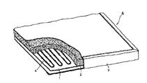
- FIG. 1 is a perspective view showing an appearance of a mantle heater.
- FIG. 2 is an enlarged perspective view showing a part of a heating portion of the mantle heater shown in FIG.
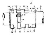
- FIG. 3 is a side view showing a state where the mantle heater shown in FIG. 1 is mounted on a pipe.
- FIG. 4 is an enlarged perspective view showing an example of a heater wire.
- FIG. 5 is an enlarged perspective view showing another example of the heater wire.
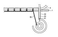
- FIG. 6 is a schematic diagram showing an example (main sewing) of the heater wire sewing method.
- FIG. 1 is a perspective view showing an appearance of a mantle heater as an example of a heater device to which a sheet with a heater wire of the present invention is applied
- FIG. 2 is an enlarged perspective view showing a part of a heating portion
- FIG. 3 is a mantle. It is a side view which shows the state which attached the heater to piping.
- the mantle heater A is sewed on the surface of the sheet-like base material 1 having heat insulation and flexibility on the surface on which the heater wires 4 are sewn in a predetermined pattern, and the heater wires 4 are further sewn.
- the heat insulating material 2 is laminated, the whole is surrounded by a bag-like cover member 3, and a power connection terminal or connector 7 is attached to a lead wire 6 drawn from a part of the cover member 3. Further, since the mantle heater A of this embodiment is used by being wound around a pipe, a plurality of heat-resistant cloth belts 9 having fasteners 8 are sewn on the cover member 3 in order to maintain the wound state. Then, a belt guide 10 made of the same material is sewn to a required portion, and the belt 9 is locked by the fastener 8. Then, as shown in FIG. 3, the mantle heater A is wound around the pipe B, and the belt 9 is fixed by the fastener 8. Instead of the fastener 8, a hook-and-loop fastener may be provided on the front and back surfaces of the end portion of the belt 9.
- the sheet-like substrate 1 is not limited as long as it has heat resistance and flexibility.
- An inorganic fiber cloth woven with heat-resistant fibers can be used.
- an inorganic fiber mat obtained by collecting glass fibers, ceramic fibers, silica fibers and the like and performing needle processing can be used.
- the fiber may be formed into a mat shape with an inorganic binder such as colloidal silica, alumina sol, or sodium silicate, or an organic binder such as starch.
- an inorganic binder such as colloidal silica, alumina sol, or sodium silicate
- an organic binder such as starch.
- a heat-resistant organic resin porous molded body such as aramid, polyamide, or polyimide can be used.
- the thickness of such a heat insulating material is suitably 5 to 100 mm, preferably 5 to 50 mm, and more preferably 8 to 30 mm.
- the cover member 3 is a member that suppresses dust generation from the inside.
- a cloth made of inorganic fibers such as glass fibers, silica fibers, alumina fibers, silica alumina fibers, or such inorganic fibers.
- a cloth made of a fluororesin-coated inorganic fiber obtained by coating the cloth with the following fluororesin can be used. Therefore, the mantle heater A provided with the cover member 3 is suitable for use in a clean room.
- the cover member 3 includes PTFE (polytetrafluoroethylene), PFA (tetrafluoroethylene-perfluoroalkoxyethylene copolymer), FEP (tetrafluoroethylene-hexafluoropropylene copolymer), PCTFE (polychlorotriethylene). Fluoroethylene sheet, ETFE (tetrafluoroethylene-ethylene copolymer), ECTFE (chlorotrifluoroethylene-ethylene copolymer), PVDF (polyvinylidene fluoride), or other fluororesin sheet, It is also possible to use a fluororesin fiber cloth (woven fabric) knitted with fluororesin fibers.
- the heater wire 4 is a heating element wire such as a nichrome wire or a Kanthal wire, a long fiber having electrical insulation and heat resistance, for example, a fiber thickness of 10 to 300 tex, more preferably 50 to 200 tex, for example glass fiber, It is coated with a covering formed by braiding long fibers such as silica fibers, alumina fibers, and silica alumina fibers.
- the long fibers refer to yarns including yarns, rovings, strands, filaments and the like.
- the covering body is knitted with long fibers on the outer peripheral surface of the heating element wire because the adhesiveness between the heating element wire and the covering body is increased rather than the tubular covering body is fitted on the heating element wire. That is, according to such a braided covering body, the heating element wire can be knitted so as to be tightened, so that the adhesion between the heating element wire and the covering body can be improved.
- the covering is preferably a double structure.
- the inner layer 42 made of alumina long fibers having high heat resistance and excellent protective effect, and the protective effect is inferior to alumina fibers.
- a two-layer structure with an outer layer 43 made of inexpensive silica-based long fibers can be employed.
- both the inner layer 42 and the outer layer 43 can be composed of silica-based long fibers.
- pattern followability improves with protection of the heater wire 4.
- symbol 41 in a figure is the above-mentioned exothermic strand.
- felt made of inorganic fibers may be used for the inner layer 42a.
- the inorganic short fibers are formed on the surface of the heating element 41 by immersing and passing the heating element 41 in a slurry in which the inorganic short fibers are dispersed in a binder solution.
- the assembled felt can be fixed. Since the inner layer 42a is intricately entangled with the short fibers, once formed, the inner layer 42a can maintain the fixed state even if the binder disappears by heating. Therefore, the binder does not require heat resistance, and general binders such as polyvinyl alcohol, polyethylene oxide, silicon oxide, and sodium glycolate can be used.
- inorganic short fibers such as a silica fiber, an alumina fiber, and a silica alumina fiber, etc. can be used, for example.
- a felt-like inner layer 42a is strong and has high flexibility, does not peel even when heated to a high temperature, and generates less fine powder.
- the thickness of the covering is not limited, but in the case of a two-layer structure, the inner layers 42 and 42a are preferably 100 ⁇ m or more, more preferably 300 to 1000 ⁇ m.
- the thickness of the felt inner layer 42a can be controlled by the concentration of ceramic short fibers in the slurry solution.
- the thickness of the outer layer 43 is preferably 100 ⁇ m or more, and more preferably 300 to 1000 ⁇ m. When one layer of braided long fibers is used, the thickness is preferably 100 ⁇ m or more, more preferably 300 to 2000 ⁇ m.
- the sewing thread for sewing the heater wire 4 is made by twisting fibers having heat resistance, and for example, a glass yarn or a silica yarn can be used.
- the sewing machine when manufacturing the mantle heater A, the sewing machine is used to sew with the sewing thread while supplying the heater wire 4 to the surface of the sheet-like substrate 1.
- an embroidery sewing machine can be used.
- the embroidery sewing machine can be sewn on the cloth in such a manner that the sewing thread is wound around the embroidery thread constituting the line of the embroidery pattern.
- the heater wire 4 instead of the embroidery thread, the sheet-like substrate 1 is heated. Line 4 can be sewn.
- the upper thread 55 passed through the hole 51 of the sewing needle 50 having a hole penetrates the sheet-like base material 1 together with the sewing needle 50 from above the sheet-like base material 1.
- it is a sewing method for making a seam by intersecting with the lower thread 56 on the back side of the sheet-like base material 1 and has an advantage that it is difficult to unravel and has excellent strength.
- the heater wire 4 is sewn on the surface of the sheet-like substrate 1 according to a predetermined pattern, but the pattern data is stored in a computer not shown, and the movement of the lifting cylinder of the sewing machine is controlled in accordance with the pattern by the computer. Can be automated. Moreover, since the heater wire 4 is sewn with the upper thread and the lower thread almost simultaneously with the supply to the sheet-like substrate 1, the heater wire 4 is temporarily fixed and fixed as before, or the heater wire 4 is sewn at the time of sewing. There is no need to press line 4 with a finger.
Landscapes
- Surface Heating Bodies (AREA)
- Resistance Heating (AREA)
Abstract
本発明は、耐熱性を有する柔軟性のシート状基材に、ヒータ線を縫着してなるヒータ線付きシートの製造方法であって、ミシンを用い、電気絶縁性及び耐熱性を有する長繊維を編組してなる被覆体で発熱素線を包囲したヒータ線を、所定のパターンに沿って連続的に供給しながら耐熱性縫糸によりシート状基材に縫い付ける、ヒータ線付きシートの製造方法に関する。
Description
本発明は、可撓性のシート状基材にヒータ線を縫着したヒータ線付きシート、及びその製造方法に関する。また、本発明は、前記ヒータ線付きシートを備えるヒータ装置に関する。
従来、配管や各種装置を加熱するために、ヒータ線とシート状断熱部材とを一体化したヒータ線付きシートが多用されている。このヒータ線付きシートは、シート状断熱部材の表面にヒータ線を所定のパターンで縫い付けて製造されるが、生産性を高めるためにミシンを用いてヒータ線を縫い付けることが行われている(特許文献1~4参照)。
ヒータ線付きシートを縫い付ける際、これまでは、ヒータ線を断熱部材の表面に所定のパターンに一致させて配置し、仮止めしてパターンを維持した状態で、ミシンで縫い付けている。しかし、仮止めは手作業で行われ、製造コストに反映される。また、ヒータ線をパターンに沿って追随させ、同時に指で押さえ付けながらミシンで縫い付けることも行われているが、この方法も手作業であり、製造コストに反映される。
このように、従来のミシンによる縫い付け方法では、人手に頼る部分が大きく、製造コストを抑える上で障害になっている。そこで本発明は、より簡便な方法によりヒータ線付きシートを製造して、低コスト化を図ることを目的とする。
上記目的を達成するために、本発明は下記を提供する。
(1)耐熱性を有する柔軟性のシート状基材に、ヒータ線を縫着してなるヒータ線付きシートの製造方法であって、
ミシンを用い、電気絶縁性及び耐熱性を有する長繊維を編組してなる被覆体で発熱素線を包囲したヒータ線を、所定のパターンに沿って連続的に供給しながら耐熱性縫糸によりシート状基材に縫い付ける、ヒータ線付きシートの製造方法。
(2)前記ミシンが刺繍用ミシンである、上記(1)記載のヒータ線付きシートの製造方法。
(3)前記被覆体が2重構造である、上記(1)または(2)記載のヒータ線付きシートの製造方法。
(4)上記(1)~(3)の何れか1項に記載の方法により得られ、
耐熱性を有する柔軟性のシート状基材の表面に、電気絶縁性及び耐熱性を有する長繊維を編組してなる被覆体で発熱素線を包囲したヒータ線が、所定のパターンに沿って耐熱性縫糸により縫着されている、ヒータ線付きシート。
(5)前記被覆体が2重構造である、上記(4)記載のヒータ線付きシート。
(6)上記(4)または(5)に記載のヒータ線付きシートと、ヒータ線付きシートの少なくともヒータ線が縫着された側の面を覆う柔軟性を有する耐熱性のカバー部材とを備える、ヒータ装置。
(7)配管加熱用であり、クリーンルーム内で使用される、上記(6)に記載のヒータ装置。
(1)耐熱性を有する柔軟性のシート状基材に、ヒータ線を縫着してなるヒータ線付きシートの製造方法であって、
ミシンを用い、電気絶縁性及び耐熱性を有する長繊維を編組してなる被覆体で発熱素線を包囲したヒータ線を、所定のパターンに沿って連続的に供給しながら耐熱性縫糸によりシート状基材に縫い付ける、ヒータ線付きシートの製造方法。
(2)前記ミシンが刺繍用ミシンである、上記(1)記載のヒータ線付きシートの製造方法。
(3)前記被覆体が2重構造である、上記(1)または(2)記載のヒータ線付きシートの製造方法。
(4)上記(1)~(3)の何れか1項に記載の方法により得られ、
耐熱性を有する柔軟性のシート状基材の表面に、電気絶縁性及び耐熱性を有する長繊維を編組してなる被覆体で発熱素線を包囲したヒータ線が、所定のパターンに沿って耐熱性縫糸により縫着されている、ヒータ線付きシート。
(5)前記被覆体が2重構造である、上記(4)記載のヒータ線付きシート。
(6)上記(4)または(5)に記載のヒータ線付きシートと、ヒータ線付きシートの少なくともヒータ線が縫着された側の面を覆う柔軟性を有する耐熱性のカバー部材とを備える、ヒータ装置。
(7)配管加熱用であり、クリーンルーム内で使用される、上記(6)に記載のヒータ装置。
本発明によれば、ヒータ線をパターンに一致させて仮止めしたり、パターンに追従して指で押さえながら縫い付ける方法のような手作業が不要になり、製造コストを低減することができる。また、ヒータ線の被覆体が長繊維を組編したものであるため、ヒータ線をシート状基材に供給する際の送り出しが円滑に行われるようになり、ヒータ線を曲率半径が小さいパターンや、複雑なパターンにも良好に追従させることができる。
以下、適宜図面を参照して本発明を詳細に説明する。
図1は本発明のヒータ線付きシートを応用したヒータ装置の一例としてのマントルヒータの外観を示す斜視図であり、図2は加熱部分の一部を示す拡大斜視図であり、図3はマントルヒータを配管に装着した状態を示す側面図である。図示されるように、マントルヒータAは、断熱性で柔軟性を有するシート状基材1の表面に、ヒータ線4を所定のパターンに縫い付け、更にヒータ線4が縫い付けられた面上に断熱材2を積層し、全体を袋状のカバー部材3で包囲し、更にカバー部材3の一部から引き出したリード線6に電源接続用端子またはコネクタ7を取り付けて構成されている。また、本態様のマントルヒータAは配管に巻き付けて使用されるため、巻き付けた状態を保持するために、カバー部材3には、留め具8を有する複数本の耐熱クロス製のベルト9が縫着され、所要部位に、同様な材料で作ったベルトガイド10が縫着されており、ベルト9を留め具8で係止する構成になっている。そして、図3に示すように、マントルヒータAを配管Bに巻き付け、ベルト9を留め具8により固定する。尚、留め具8に代えて、ベルト9の端部の表裏面に面ファスナーを付設してもよい。
シート状基材1は、耐熱性及び柔軟性を有する限り制限はないが、例えばシリコンスポンジ製のシート、無機繊維ブランケット、耐熱性ゴムシート、ガラス繊維や、シリカ繊維、アルミナ繊維、シリカアルミナ繊維といった耐熱性繊維を織り込んだ無機繊維製クロス等を使用できる。
断熱材2は、ガラスファイバーやセラミックファイバー、シリカファイバー等を集成し、ニードル加工を施した無機繊維マットを使用できる。また、上記ファイバーをコロイダルシリカやアルミナゾル、ケイ酸ソーダ等の無機質バインダーや、でんぷんなどの有機質バインダーでマット状に成形してもよい。あるいは、アラミドやポリアミド、ポリイミド等の耐熱性の有機樹脂製多孔質成形体を使用することもできる。こうした断熱材の厚さは、5~100mmが適当であり、5~50mmが好適であり、8~30mmがさらに好適である。
カバー部材3は内部からの発塵を抑える部材であり、例えばガラス繊維や、シリカ繊維、アルミナ繊維、シリカアルミナ繊維といった無機繊維からなる無機繊維製クロス(織布)、あるいはこういった無機繊維製クロスに下記フッ素系樹脂をコーティング処理したフッ素樹脂コーティング無機繊維製クロスを使用できる。従って、カバー部材3を備えたマントルヒータAは、クリーンルームでの使用に好適となる。
また、カバー部材3として、PTFE(ポリテトラフォルオロエチレン)、PFA(テトラフルオロエチレン-パーフルオロアルコキシエチレン共重合体)、FEP(テトラフルオロエチレン-ヘキサフルオロプロピレン共重合体)、PCTFE(ポリクロロトリフルオロエチレン)、ETFE(テトラフルオロエチレン-エチレン共重合体)、ECTFE(クロロトリフルオロエチレン-エチレン共重合体)、PVDF(ポリビニリデンフロライド)等のフッ素系樹脂からなるフッ素樹脂製シート、あるいは前記のフッ素系樹脂の繊維を編んだフッ素樹脂繊維製クロス(織布)を使用することもできる。
さらに、上記フッ素系樹脂以外にポリアミド、ポリカーボネート、ポリアセタール、ポリブチレンテレフタレート、変性ポリフェニレンエーテル、ポリフェニレンサルファイド、ポリサルホン、ポリエーテルサルホン、ポリアリレート、ポリエーテルエーテルケルトン、ポリフタルアミド、ポリイミド、ポリエーテルイミド、ポリメチルペンテン等の耐熱性ではあるが、フッ素系樹脂よりは低融点の樹脂も使用できる。
ヒータ線4は、ニクロム線やカンタル線等の発熱素線を、電気絶縁性及び耐熱性を有する長繊維、例えば繊維太さが10~300tex、より好ましくは50~200texの、例えばガラス繊維や、シリカ繊維、アルミナ繊維、シリカアルミナ繊維といった長繊維を編組してなる被覆体で被覆したものである。ここで、長繊維とは、ヤーン、ロービング、ストランド、フィラメントなどを含む糸状のものをいう。長繊維を用いることにより、絶縁性が高まるとともに摺動性も高まり、後述するように、シート状基材1に縫い付ける際にミシンから所定のパターンに押し出しやすくなる。また、被覆体は、発熱素線の外周面に長繊維を編み込む方が、筒状の被覆体を発熱素線に被嵌するよりも発熱素線と被覆体との密着性が増して好ましい。すなわち、こうした編組してなる被覆体によれば、発熱素線を締め付けるように編み込むことができるので発熱素線と被覆体との密着性を高めることができる。
また、被覆体は2重構造にすることが好ましく、例えば図4に示すように、耐熱性が高く保護効果により優れるアルミナ系長繊維からなる内層42と、アルミナ系繊維よりは保護効果が劣るものの安価であるシリカ系長繊維からなる外層43との2層構造とすることができる。また、内層42、外層43ともにシリカ系長繊維により構成することもできる。これにより、ヒータ線4の保護とともに、パターン追従性が高まる。尚、図中の符号41は、上記した発熱素線である。
また、図5に示すように、無機繊維製のフェルトを内層42aに用いてもよい。このフェルト状の内層42aを製造するには、バインダー溶液に無機短繊維を分散させたスラリーに発熱素線41を浸して通過させ、乾燥することにより、発熱素線41の表面に無機短繊維が集成したフェルトを固着させることができる。内層42aは、短繊維が複雑に絡み合っているために、一旦形成された後は加熱によりバインダーが消失しても固着した状態を維持し続けることができる。そのため、バインダーは耐熱性を必要とせず、ポリビニルアルコール、ポリエチレンオキサイド、酸化ケイ素、グリコール酸ナトリウム等の一般的なバインダーを使用することができる。また、無機短繊維としては、例えばシリカ繊維、アルミナ繊維、シリカアルミナ繊維といった無機短繊維等を使用することができる。このようなフェルト状の内層42aは、強固であるとともに、高い柔軟性を備えており、高温に加熱されても剥離することが無く、微粉の発生も少ない。
被覆体の厚さには制限はないが、2層構造の場合は、内層42、42aを100μm以上にすることが好ましく、300~1000μmがより好ましい。尚、フェルト状の内層42aの厚さは、スラリー溶液におけるセラミック短繊維の濃度により制御することができる。また、外層43の厚さは100μm以上にすることが好ましく、300~1000μmがより好ましい。長繊維を編組したものを1層で用いる場合は、その厚さは100μm以上にすることが好ましく、300~2000μmがより好ましい。
尚、ヒータ線4を縫い付ける縫糸は、耐熱性を有する繊維を撚り合わせたものであり、例えばガラスヤーンやシリカヤーンを用いることができる。
本発明では、上記のマントルヒータAを製造する際、ミシンを用い、シート状基材1の表面にヒータ線4を供給しながら、縫糸で縫い付ける。このような縫い付けを実施するには、刺繍用ミシンを用いることができる。刺繍用ミシンは、刺繍模様の線を構成する刺繍糸に、縫糸を巻き付けるようにして布に縫い付けることができ、刺繍糸の代わりにヒータ線4を用いることで、シート状基材1にヒータ線4を縫い付けることができる。
縫い方に制限はないが、本縫いや単環縫いを行うことができる。本縫いは、図6に示すように、シート状基材1の上から、穴のあいたミシン針50の穴51に通された上糸55が、ミシン針50ごとシート状基材1を貫通し、その際シート状基材1の裏側の下糸56と交差させ、縫い目を作る縫い方であり、解けにくく強度に優れるなどの利点を有する。
ヒータ線4は所定のパターンに従いシート状基材1の表面に縫い付けられるが、パターンのデータは図示されないコンピュータに格納されており、ミシンの昇降筒の動きをコンピュータでパターンに合わせて制御することにより、自動化が可能である。しかも、ヒータ線4は、シート状基材1に供給されるのとほぼ同時に上糸や下糸により縫い付けられるため、従来のように、ヒータ線4を仮縫いして固定したり、縫製時にヒータ線4を指で押える必要もない。
本発明を詳細に、また特定の実施態様を参照して説明したが、本発明の精神と範囲を逸脱することなく、様々な修正や変更を加えることができることは、当業者にとって明らかである。
本出願は、2011年3月30日出願の日本特許出願2011-075609号に基づくものであり、その内容はここに参照として取り込まれる。
本出願は、2011年3月30日出願の日本特許出願2011-075609号に基づくものであり、その内容はここに参照として取り込まれる。
A マントルヒータ
1 シート状基材
2 断熱材
3 カバー部材
4 ヒータ線
8 留め具
9 ベルト
41 発熱素線
42、42a 内層
43 外層
1 シート状基材
2 断熱材
3 カバー部材
4 ヒータ線
8 留め具
9 ベルト
41 発熱素線
42、42a 内層
43 外層
Claims (7)
- 耐熱性を有する柔軟性のシート状基材に、ヒータ線を縫着してなるヒータ線付きシートの製造方法であって、
ミシンを用い、電気絶縁性及び耐熱性を有する長繊維を編組してなる被覆体で発熱素線を包囲したヒータ線を、所定のパターンに沿って連続的に供給しながら耐熱性縫糸によりシート状基材に縫い付ける、ヒータ線付きシートの製造方法。 - 前記ミシンが刺繍用ミシンである、請求項1記載のヒータ線付きシートの製造方法。
- 前記被覆体が2重構造である、請求項1または2記載のヒータ線付きシートの製造方法。
- 請求項1~3の何れか1項に記載の方法により得られ、
耐熱性を有する柔軟性のシート状基材の表面に、電気絶縁性及び耐熱性を有する長繊維を編組してなる被覆体で発熱素線を包囲したヒータ線が、所定のパターンに沿って耐熱性縫糸により縫着されている、ヒータ線付きシート。 - 前記被覆体が2重構造である、請求項4記載のヒータ線付きシート。
- 請求項4または5に記載のヒータ線付きシートと、ヒータ線付きシートの少なくともヒータ線が縫着された側の面を覆う柔軟性を有する耐熱性のカバー部材とを備える、ヒータ装置。
- 配管加熱用であり、クリーンルーム内で使用される、請求項6に記載のヒータ装置。
Applications Claiming Priority (2)
| Application Number | Priority Date | Filing Date | Title |
|---|---|---|---|
| JP2011-075609 | 2011-03-30 | ||
| JP2011075609A JP5635440B2 (ja) | 2011-03-30 | 2011-03-30 | ヒータ線付きシート及びその製造方法、並びにヒータ装置 |
Publications (1)
| Publication Number | Publication Date |
|---|---|
| WO2012133588A1 true WO2012133588A1 (ja) | 2012-10-04 |
Family
ID=46931295
Family Applications (1)
| Application Number | Title | Priority Date | Filing Date |
|---|---|---|---|
| PCT/JP2012/058252 Ceased WO2012133588A1 (ja) | 2011-03-30 | 2012-03-28 | ヒータ線付きシート及びその製造方法、並びにヒータ装置 |
Country Status (3)
| Country | Link |
|---|---|
| JP (1) | JP5635440B2 (ja) |
| TW (1) | TWI612840B (ja) |
| WO (1) | WO2012133588A1 (ja) |
Cited By (1)
| Publication number | Priority date | Publication date | Assignee | Title |
|---|---|---|---|---|
| KR20220031718A (ko) * | 2019-07-16 | 2022-03-11 | 얼링클링거 아게 | 실딩 부품 |
Families Citing this family (3)
| Publication number | Priority date | Publication date | Assignee | Title |
|---|---|---|---|---|
| JP6285763B2 (ja) * | 2013-03-26 | 2018-02-28 | イビデン株式会社 | 排ガス浄化装置の製造方法 |
| JP2014190191A (ja) * | 2013-03-26 | 2014-10-06 | Ibiden Co Ltd | 排ガス浄化装置用の保持シール材、該保持シール材の製造方法、排ガス浄化装置、及び、排ガス浄化装置の製造方法 |
| CN104519604B (zh) * | 2014-12-23 | 2017-01-04 | 邵明義 | 合金发热片的制造方法 |
Citations (4)
| Publication number | Priority date | Publication date | Assignee | Title |
|---|---|---|---|---|
| JPH05326115A (ja) * | 1992-05-15 | 1993-12-10 | Matsushita Electric Works Ltd | 面状発熱体の製造方法 |
| JPH1064668A (ja) * | 1996-08-12 | 1998-03-06 | Nichias Corp | マントルヒータおよびその製造方法 |
| JP2002164156A (ja) * | 2000-11-24 | 2002-06-07 | Kotobuki Kogyo Kk | シートヒーターの製造方法 |
| JP2010097809A (ja) * | 2008-10-16 | 2010-04-30 | Blueball Co Ltd | 電熱ヒーター |
Family Cites Families (2)
| Publication number | Priority date | Publication date | Assignee | Title |
|---|---|---|---|---|
| JP2621437B2 (ja) * | 1988-11-10 | 1997-06-18 | 松下電器産業株式会社 | ヒータユニット |
| JP2003347017A (ja) * | 2002-05-29 | 2003-12-05 | Mitsui Kozan Material Kk | 被覆ヒーター線及び電熱ヒーター |
-
2011
- 2011-03-30 JP JP2011075609A patent/JP5635440B2/ja active Active
-
2012
- 2012-03-28 WO PCT/JP2012/058252 patent/WO2012133588A1/ja not_active Ceased
- 2012-03-30 TW TW101111293A patent/TWI612840B/zh active
Patent Citations (4)
| Publication number | Priority date | Publication date | Assignee | Title |
|---|---|---|---|---|
| JPH05326115A (ja) * | 1992-05-15 | 1993-12-10 | Matsushita Electric Works Ltd | 面状発熱体の製造方法 |
| JPH1064668A (ja) * | 1996-08-12 | 1998-03-06 | Nichias Corp | マントルヒータおよびその製造方法 |
| JP2002164156A (ja) * | 2000-11-24 | 2002-06-07 | Kotobuki Kogyo Kk | シートヒーターの製造方法 |
| JP2010097809A (ja) * | 2008-10-16 | 2010-04-30 | Blueball Co Ltd | 電熱ヒーター |
Cited By (3)
| Publication number | Priority date | Publication date | Assignee | Title |
|---|---|---|---|---|
| KR20220031718A (ko) * | 2019-07-16 | 2022-03-11 | 얼링클링거 아게 | 실딩 부품 |
| JP2022541272A (ja) * | 2019-07-16 | 2022-09-22 | アーリングクリンジャー アーゲー | 遮蔽部材 |
| KR102816979B1 (ko) * | 2019-07-16 | 2025-06-09 | 얼링클링거 아게 | 실딩 부품 |
Also Published As
| Publication number | Publication date |
|---|---|
| JP5635440B2 (ja) | 2014-12-03 |
| JP2012209208A (ja) | 2012-10-25 |
| TW201240511A (en) | 2012-10-01 |
| TWI612840B (zh) | 2018-01-21 |
Similar Documents
| Publication | Publication Date | Title |
|---|---|---|
| TW535453B (en) | Electric heating/warming fabric articles | |
| WO2009145536A2 (ko) | 도전성 패드 및 그 제조방법 | |
| JP5635440B2 (ja) | ヒータ線付きシート及びその製造方法、並びにヒータ装置 | |
| CN102713037A (zh) | 导电织物及其制造方法和设备 | |
| JP2010097809A (ja) | 電熱ヒーター | |
| JP6512816B2 (ja) | ヒータユニット及びステアリングホイール | |
| KR20150078804A (ko) | 도전성 면상체 및 그 제조방법 | |
| KR200463236Y1 (ko) | 자수 제조방식의 면상도전체 | |
| JP2016037680A (ja) | 繊維製品及び糸材の製造方法 | |
| KR20180080950A (ko) | 부분 고정방식의 기능성선재가 부설된 면상체, 그 제조장치 및 제조방법 | |
| KR20130108954A (ko) | 기모층을 갖는 도전선, 그 제조방법, 및 그를 구비한 면상체 | |
| KR20250110864A (ko) | 선 형상체를 구비한 면 형상 유닛, 스티어링 휠 및 면 형상 유닛의 제조 방법 | |
| KR20180127076A (ko) | 융착고정식 기능성선재가 구비된 면상체 및 그 제조장치 | |
| JP6228002B2 (ja) | 搬送ベルト | |
| TW202547209A (zh) | 加熱器裝置及加熱器裝置的製造方法 | |
| KR102931560B1 (ko) | 면 형상 유닛, 스티어링 휠, 및 면 형상 유닛의 제조 방법 | |
| KR20140099793A (ko) | 자수 제조방식의 면상 시트 및 그 제조방법 | |
| KR20130065555A (ko) | 스티어링휠용 히팅장치 및 그 제조방법 | |
| KR20160088022A (ko) | 도전성 면상체, 그 제조방법 및 제조장치 | |
| KR101977097B1 (ko) | 직물히터, 이를 포함하는 시트 및 매트 | |
| KR20150078805A (ko) | 도전성 면상체 및 그 제조방법 | |
| TW202546371A (zh) | 加熱器裝置及加熱器裝置的製造方法 | |
| KR20140083841A (ko) | 면상도전체의 도전성 선재 배치구조 | |
| KR20110099606A (ko) | 자수 제조방식의 면상도전체 | |
| KR20120075371A (ko) | 면상 히터 |
Legal Events
| Date | Code | Title | Description |
|---|---|---|---|
| 121 | Ep: the epo has been informed by wipo that ep was designated in this application |
Ref document number: 12765235 Country of ref document: EP Kind code of ref document: A1 |
|
| NENP | Non-entry into the national phase |
Ref country code: DE |
|
| 122 | Ep: pct application non-entry in european phase |
Ref document number: 12765235 Country of ref document: EP Kind code of ref document: A1 |