WO2012133539A1 - ラジアントチューブ - Google Patents
ラジアントチューブ Download PDFInfo
- Publication number
- WO2012133539A1 WO2012133539A1 PCT/JP2012/058158 JP2012058158W WO2012133539A1 WO 2012133539 A1 WO2012133539 A1 WO 2012133539A1 JP 2012058158 W JP2012058158 W JP 2012058158W WO 2012133539 A1 WO2012133539 A1 WO 2012133539A1
- Authority
- WO
- WIPO (PCT)
- Prior art keywords
- pipe
- bend
- radiant tube
- bend pipe
- straight
- Prior art date
- Legal status (The legal status is an assumption and is not a legal conclusion. Google has not performed a legal analysis and makes no representation as to the accuracy of the status listed.)
- Ceased
Links
Images
Classifications
-
- F—MECHANICAL ENGINEERING; LIGHTING; HEATING; WEAPONS; BLASTING
- F23—COMBUSTION APPARATUS; COMBUSTION PROCESSES
- F23C—METHODS OR APPARATUS FOR COMBUSTION USING FLUID FUEL OR SOLID FUEL SUSPENDED IN A CARRIER GAS OR AIR
- F23C3/00—Combustion apparatus characterised by the shape of the combustion chamber
- F23C3/002—Combustion apparatus characterised by the shape of the combustion chamber the chamber having an elongated tubular form, e.g. for a radiant tube
-
- F—MECHANICAL ENGINEERING; LIGHTING; HEATING; WEAPONS; BLASTING
- F23—COMBUSTION APPARATUS; COMBUSTION PROCESSES
- F23D—BURNERS
- F23D14/00—Burners for combustion of a gas, e.g. of a gas stored under pressure as a liquid
- F23D14/12—Radiant burners
-
- B—PERFORMING OPERATIONS; TRANSPORTING
- B01—PHYSICAL OR CHEMICAL PROCESSES OR APPARATUS IN GENERAL
- B01J—CHEMICAL OR PHYSICAL PROCESSES, e.g. CATALYSIS OR COLLOID CHEMISTRY; THEIR RELEVANT APPARATUS
- B01J12/00—Chemical processes in general for reacting gaseous media with gaseous media; Apparatus specially adapted therefor
- B01J12/007—Chemical processes in general for reacting gaseous media with gaseous media; Apparatus specially adapted therefor in the presence of catalytically active bodies, e.g. porous plates
-
- B—PERFORMING OPERATIONS; TRANSPORTING
- B01—PHYSICAL OR CHEMICAL PROCESSES OR APPARATUS IN GENERAL
- B01J—CHEMICAL OR PHYSICAL PROCESSES, e.g. CATALYSIS OR COLLOID CHEMISTRY; THEIR RELEVANT APPARATUS
- B01J19/00—Chemical, physical or physico-chemical processes in general; Their relevant apparatus
- B01J19/24—Stationary reactors without moving elements inside
-
- B—PERFORMING OPERATIONS; TRANSPORTING
- B01—PHYSICAL OR CHEMICAL PROCESSES OR APPARATUS IN GENERAL
- B01J—CHEMICAL OR PHYSICAL PROCESSES, e.g. CATALYSIS OR COLLOID CHEMISTRY; THEIR RELEVANT APPARATUS
- B01J4/00—Feed or outlet devices; Feed or outlet control devices
- B01J4/001—Feed or outlet devices as such, e.g. feeding tubes
-
- B—PERFORMING OPERATIONS; TRANSPORTING
- B01—PHYSICAL OR CHEMICAL PROCESSES OR APPARATUS IN GENERAL
- B01J—CHEMICAL OR PHYSICAL PROCESSES, e.g. CATALYSIS OR COLLOID CHEMISTRY; THEIR RELEVANT APPARATUS
- B01J8/00—Chemical or physical processes in general, conducted in the presence of fluids and solid particles; Apparatus for such processes
- B01J8/02—Chemical or physical processes in general, conducted in the presence of fluids and solid particles; Apparatus for such processes with stationary particles, e.g. in fixed beds
- B01J8/06—Chemical or physical processes in general, conducted in the presence of fluids and solid particles; Apparatus for such processes with stationary particles, e.g. in fixed beds in tube reactors; the solid particles being arranged in tubes
-
- C—CHEMISTRY; METALLURGY
- C01—INORGANIC CHEMISTRY
- C01B—NON-METALLIC ELEMENTS; COMPOUNDS THEREOF; METALLOIDS OR COMPOUNDS THEREOF NOT COVERED BY SUBCLASS C01C
- C01B33/00—Silicon; Compounds thereof
- C01B33/08—Compounds containing halogen
- C01B33/107—Halogenated silanes
-
- C—CHEMISTRY; METALLURGY
- C01—INORGANIC CHEMISTRY
- C01B—NON-METALLIC ELEMENTS; COMPOUNDS THEREOF; METALLOIDS OR COMPOUNDS THEREOF NOT COVERED BY SUBCLASS C01C
- C01B33/00—Silicon; Compounds thereof
- C01B33/08—Compounds containing halogen
- C01B33/107—Halogenated silanes
- C01B33/1071—Tetrachloride, trichlorosilane or silicochloroform, dichlorosilane, monochlorosilane or mixtures thereof
-
- C—CHEMISTRY; METALLURGY
- C01—INORGANIC CHEMISTRY
- C01B—NON-METALLIC ELEMENTS; COMPOUNDS THEREOF; METALLOIDS OR COMPOUNDS THEREOF NOT COVERED BY SUBCLASS C01C
- C01B33/00—Silicon; Compounds thereof
- C01B33/08—Compounds containing halogen
- C01B33/107—Halogenated silanes
- C01B33/1071—Tetrachloride, trichlorosilane or silicochloroform, dichlorosilane, monochlorosilane or mixtures thereof
- C01B33/10742—Tetrachloride, trichlorosilane or silicochloroform, dichlorosilane, monochlorosilane or mixtures thereof prepared by hydrochlorination of silicon or of a silicon-containing material
- C01B33/10757—Tetrachloride, trichlorosilane or silicochloroform, dichlorosilane, monochlorosilane or mixtures thereof prepared by hydrochlorination of silicon or of a silicon-containing material with the preferential formation of trichlorosilane
-
- F—MECHANICAL ENGINEERING; LIGHTING; HEATING; WEAPONS; BLASTING
- F23—COMBUSTION APPARATUS; COMBUSTION PROCESSES
- F23D—BURNERS
- F23D14/00—Burners for combustion of a gas, e.g. of a gas stored under pressure as a liquid
- F23D14/46—Details
- F23D14/66—Preheating the combustion air or gas
-
- F—MECHANICAL ENGINEERING; LIGHTING; HEATING; WEAPONS; BLASTING
- F24—HEATING; RANGES; VENTILATING
- F24H—FLUID HEATERS, e.g. WATER OR AIR HEATERS, HAVING HEAT-GENERATING MEANS, e.g. HEAT PUMPS, IN GENERAL
- F24H3/00—Air heaters
- F24H3/006—Air heaters using fluid fuel
-
- F—MECHANICAL ENGINEERING; LIGHTING; HEATING; WEAPONS; BLASTING
- F24—HEATING; RANGES; VENTILATING
- F24H—FLUID HEATERS, e.g. WATER OR AIR HEATERS, HAVING HEAT-GENERATING MEANS, e.g. HEAT PUMPS, IN GENERAL
- F24H9/00—Details
- F24H9/12—Arrangements for connecting heaters to circulation pipes
-
- F—MECHANICAL ENGINEERING; LIGHTING; HEATING; WEAPONS; BLASTING
- F27—FURNACES; KILNS; OVENS; RETORTS
- F27B—FURNACES, KILNS, OVENS OR RETORTS IN GENERAL; OPEN SINTERING OR LIKE APPARATUS
- F27B17/00—Furnaces of a kind not covered by any of groups F27B1/00 - F27B15/00
- F27B17/0016—Chamber type furnaces
-
- F—MECHANICAL ENGINEERING; LIGHTING; HEATING; WEAPONS; BLASTING
- F27—FURNACES; KILNS; OVENS; RETORTS
- F27D—DETAILS OR ACCESSORIES OF FURNACES, KILNS, OVENS OR RETORTS, IN SO FAR AS THEY ARE OF KINDS OCCURRING IN MORE THAN ONE KIND OF FURNACE
- F27D99/00—Subject matter not provided for in other groups of this subclass
- F27D99/0001—Heating elements or systems
- F27D99/0033—Heating elements or systems using burners
- F27D99/0035—Heating indirectly through a radiant surface
-
- B—PERFORMING OPERATIONS; TRANSPORTING
- B01—PHYSICAL OR CHEMICAL PROCESSES OR APPARATUS IN GENERAL
- B01J—CHEMICAL OR PHYSICAL PROCESSES, e.g. CATALYSIS OR COLLOID CHEMISTRY; THEIR RELEVANT APPARATUS
- B01J2219/00—Chemical, physical or physico-chemical processes in general; Their relevant apparatus
- B01J2219/00049—Controlling or regulating processes
- B01J2219/00051—Controlling the temperature
- B01J2219/0015—Controlling the temperature by thermal insulation means
- B01J2219/00155—Controlling the temperature by thermal insulation means using insulating materials or refractories
-
- B—PERFORMING OPERATIONS; TRANSPORTING
- B01—PHYSICAL OR CHEMICAL PROCESSES OR APPARATUS IN GENERAL
- B01J—CHEMICAL OR PHYSICAL PROCESSES, e.g. CATALYSIS OR COLLOID CHEMISTRY; THEIR RELEVANT APPARATUS
- B01J2219/00—Chemical, physical or physico-chemical processes in general; Their relevant apparatus
- B01J2219/00049—Controlling or regulating processes
- B01J2219/00051—Controlling the temperature
- B01J2219/00157—Controlling the temperature by means of a burner
-
- Y—GENERAL TAGGING OF NEW TECHNOLOGICAL DEVELOPMENTS; GENERAL TAGGING OF CROSS-SECTIONAL TECHNOLOGIES SPANNING OVER SEVERAL SECTIONS OF THE IPC; TECHNICAL SUBJECTS COVERED BY FORMER USPC CROSS-REFERENCE ART COLLECTIONS [XRACs] AND DIGESTS
- Y02—TECHNOLOGIES OR APPLICATIONS FOR MITIGATION OR ADAPTATION AGAINST CLIMATE CHANGE
- Y02E—REDUCTION OF GREENHOUSE GAS [GHG] EMISSIONS, RELATED TO ENERGY GENERATION, TRANSMISSION OR DISTRIBUTION
- Y02E20/00—Combustion technologies with mitigation potential
- Y02E20/34—Indirect CO2mitigation, i.e. by acting on non CO2directly related matters of the process, e.g. pre-heating or heat recovery
Definitions
- the present invention comprises a cast metal pipe, comprising at least one bend pipe and a pair of straight pipes connected to both ends of the bend pipe, and a radiant into which combustion gas of a burner is blown from one of the pair of straight pipes Regarding the tube.
- Patent Document 1 shown below as prior art document information related to this type of radiant tube.
- This Patent Document 1 discloses a radiant tube in which a neck portion extending linearly with a required length is provided at two open ends of a bend pipe. In this configuration, a welded portion between a bend pipe and a straight pipe is disclosed. In addition, since the compressive stress on the bend pipe side and the compressive stress on the straight pipe side act equally, the stress due to thermal expansion occurring in the welded portion is equalized, and it is described that cracks are less likely to occur in the welded portion.
- the bend tube is divided into a large-diameter portion on the outer peripheral side with respect to the arc-shaped central axis of the bend tube and a small-diameter portion on the inner peripheral side with respect to the central axis.
- the large diameter portion and the small diameter portion are welded in a state of facing each other. Therefore, apart from the problem of the welded portion between the bend pipe and the straight pipe, there is a possibility that cracks due to thermal expansion or the like may occur at two weld locations extending along the axis of the bend pipe.
- the object of the present invention is highly durable against harsh thermal conditions from the combustion gas blown by the burner and used for a longer period of time. It is to provide a possible radiant tube.
- the characteristic configuration of the radiant tube according to the present invention is: A radiant tube made of heat-resistant metal comprising at least one bend pipe connecting a pair of straight pipes, into which combustion gas of a burner is blown from one of the pair of straight pipes, At least a cast body having an outer diameter of 150 to 210 mm and a wall thickness of 3 to 8 mm is used as the bend pipe closest to the burner.
- a cast body having a wall thickness of 3 to 8 mm is used as the bend pipe closest to the burner with the most severe thermal conditions.
- the thickness of the pipe becomes more uniform, and there is no stress concentration spot such as a weld extending in the longitudinal direction of the bend pipe. Therefore, a rapid temperature rise due to the burner combustion gas and a heat crack due to a rapid temperature drop are unlikely to occur, and as a result, a radiant tube having high heat resistance and withstanding long-term use was obtained.
- the thickness of the cast body is reduced to 3 to 8 mm, the denseness of the metal structure is enhanced based on the increase in the cooling rate during casting. Therefore, the heat resistance and thermal shock resistance of the bend pipe closest to the burner having the severest thermal conditions were improved, and a radiant tube that can withstand a longer period of use was obtained.
- the bend pipe closest to the burner is thinned, the radiant tube is lightened as a whole, reducing the labor required for the replacement work.
- Another feature of the present invention is that the thickness of the bend pipe in the vicinity of the connection with the straight pipe is made thinner than other portions of the bend pipe.
- the joint part of a bend pipe with a straight pipe is a part that is particularly prone to lack of strength during use due to insufficient structural strength such as close to the pipe end face or weakening of the material due to heat received during welding for connection. It becomes.
- the thickness of the vicinity of the connection is made thinner than other parts of the bend tube, so the metal structure is particularly dense due to the increased cooling rate during casting.
- the durability comparable to the general part of the bend pipe excluding the vicinity of the connection is ensured against severe thermal conditions from the combustion gas.
- Another characteristic configuration of the present invention is that a plurality of the bend pipes are provided, and a cast body having a thickness of 3 to 8 mm is used for all of the plurality of bend pipes.
- a cast body with a thickness of 3 to 8 mm may be used only for the bend pipe closest to the burner. However, with this configuration, a cast body with a thickness of 3 to 8 mm is used for all of the plurality of bend pipes. and for which, radiant tube to withstand further higher long-term use reliability of heat resistance was obtained. In addition, since the weight of the radiant tube as a whole is further increased, the burden of labor required for the replacement work is further reduced.
- Another feature of the present invention is that the thickness of the straight pipe is 7 mm or less.
- the straight pipe is made to be thin and comparable to the bend pipe, so that the strength of the connection part between the bend pipe and the straight pipe is kept high compared to the configuration in which only the straight pipe remains thick. Can do.
- Another feature of the present invention is that the thickness of the portion of the straight pipe in the vicinity of the connection with the bend pipe is made thinner than other portions of the straight pipe.
- the joint part of the straight pipe with the bend pipe is a part that is particularly prone to lack of strength during use due to insufficient structural strength such as close to the pipe end face or weakening of the material due to heat received during welding for connection. It becomes.
- the thickness in the vicinity of the connection is made thinner than other parts of the straight pipe, so the metal structure is particularly dense due to the increased cooling rate during casting.
- the durability comparable to the general part of the straight pipe excluding the vicinity of the connection is ensured against the severe thermal conditions from the combustion gas.
- Another characteristic configuration of the present invention is that a cast body having a wall thickness exceeding the wall thickness of the bend pipe is used as the straight pipe.
- This configuration makes it easier to obtain a radiant tube that has higher heat resistance and can withstand long-term use than a configuration using a straight pipe having a thickness equivalent to the thickness of the bend pipe.
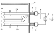
- the radiant tube 1 shown in FIG. 1 has four horizontal straight pipes 2A, 2B, 2C, and 2D juxtaposed at equal intervals in the vertical direction, and two straight pipes 2 adjacent in the vertical direction have a total of three bends.
- the tubes 3A, 3B, and 3C are connected to each other, and generally have a W-shape that is generally lateral.
- the radiant tube 1 is supported by a furnace wall 10 of a drying furnace, a firing furnace or other heat treatment furnace by an uppermost straight pipe 2A and a lowermost straight pipe 2D, and ends of the straight pipes 2A and 2D.
- a burner 5 with a heat storage element 4 made of ceramic honeycomb or the like having high heat recovery efficiency interposed therebetween.
- these burners 5 collect exhaust heat with the lower heat accumulator 4 while exhausting from the lowermost straight pipe 2D.
- the combustion air is preheated using the exhaust heat recovered by the lower heat storage body 4 to reduce the amount of fuel used for the burner combustion. Regenerative type that can be.
- Combustion air is burned by the burner 5 connected to the uppermost straight pipe 2A by the switching valve 6 interposed between the combustion air fan 7 for supplying the combustion air and each burner 5, and the exhaust heat is minimized.
- the state (indicated by the solid line) of recovery by the heat accumulator 4 connected to the lower straight pipe 2D and the combustion air are burned by the burner 5 connected to the lowermost straight pipe 2D, and the exhaust heat is discharged to the uppermost stage. It is possible to switch between a state (indicated by a broken line) in which the heat storage body 4 is connected to the straight pipe 2A.
- the exhaust gas that has passed through the heat accumulator 4 can be released to the outside air via the switching valve 6 and an exhaust gas treatment device (not shown).
- the four straight pipes 2A, 2B, 2C, and 2D and the three bend pipes 3A, 3B, and 3C constituting the radiant tube 1 all have an outer diameter of 180 mm, 20 to 35 wt% chromium, and 30 to 50 wt%. It is formed of cast steel containing nickel (an example of a refractory metal casting).
- the connection between the straight pipe 2 and the bend pipe 3 is realized by welding performed from the outer peripheral side in a state where the end faces of the pipes are attached to each other.
- a thin cast body having a thickness of 3 to 8 mm is used as the first bend pipe 3A and the third bend pipe 3C closest to the burner 5.
- cast bodies having a thickness of 5 mm or 10 mm are used as the second bend pipe 3B and the four straight pipes 2A, 2B, 2C, and 2D that are relatively separated from the burner 5.
- the terms “separation” and “proximity” as used herein mean the length of the distance from the burner 5 on the flame or combustion gas path that is emitted from the burner 5 and moves inside the radiant tube 1.
- the radiant tube 1 having high heat resistance and withstanding long-term use can be obtained.
- the bend pipe by integral molding by casting is thicker than the bend pipe obtained by welding the end faces of the left and right pipe bodies obtained by pressing the plate material along the axis of the pipe. Because it becomes more uniform and there are no stress concentration spots such as welds extending in the longitudinal direction of the bend pipe, so it is difficult for heat cracks due to sudden temperature rise or sudden temperature drop due to burner combustion gas to occur. Conceivable.
- the heat resistance and the thermal shock resistance are improved by increasing the denseness of the metal structure based on the increase in the cooling rate after casting. Conceivable. Further, since the thinning is likely to cause deformation due to stress, it is easy to absorb thermal stress, and it is considered that heat cracks are less likely to occur due to a rapid temperature rise caused by the burner combustion gas.
- the bend pipe 3 closest to the burner 5 is thinned, the temperature rise rate of the bend pipe due to the burner combustion gas is increased, and the temperature drop in the thickness direction is reduced, so that fuel consumption is reduced. The amount was also lower than before. Moreover, because it is lightweight as a whole radiant tube, also decreased burden labor required for replacement work.
- the four straight pipes 2A, 2B, 2C, 2D constituting the radiant tube 1 are manufactured using a centrifugal casting method.
- the three bend pipes 3A, 3B, and 3C all use a suction casting method in which the inside of the cavity after injecting molten metal is negatively pressured by a vacuum pump or the like. Has no shrinkage or loosening that tends to occur during solidification of molten metal, and a bend tube with a good surface texture has been obtained.
- it may attempt to thin even using a suction casting method in straight pipe.
- the outer diameters of the four horizontal straight pipes 2A, 2B, 2C, 2D and the three bend pipes 3A, 3B, 3C constituting the radiant tube 1 are not limited to 180 mm, but may be in the range of 150 to 210 mm. Within this range, the effect of setting the thickness of the bend pipes 3A, 3B, 3C to 3 to 8 mm is easily obtained.
- Table 1 shows the results of analyzing various characteristics related to thermal stress received by the third bend pipe 3C by simulation when the radiant tube 1 shown in FIG. 1 is actually used. In this simulation, combustion gas was alternately supplied from each burner 5 over a certain period and burned, imitating use as a regenerative type.
- each bend pipe 3 and each straight pipe 2 As shown in Table 1, by changing the wall thickness of each bend pipe 3 and each straight pipe 2 in various ways, the combustion gas is alternately supplied from each burner 5 over a certain period of time. Thus, the relationship with various characteristics related to thermal stress received by the third bend pipe 3C was obtained.
- the numerical values of the bend pipe thickness shown in the table are applied to all the three bend pipes 3A, 3B, 3C.
- the numerical values of the straight pipe thickness are four straight pipes 2A, 2B, 2C, It is applied to all 2D.
- KHR-48N was used as a casting material.
- KHR-48N is an austenitic superalloy having excellent oxidation resistance and creep rupture strength up to 1200 ° C., and contains 27% by weight of chromium, 47% by weight of nickel and 5% by weight of tungsten.
- each tendency mentioned above can be seen basically consistently in both cases where the thickness of the portion of the straight pipe 2 is 5 mm and 10 mm, and may not be greatly influenced by the thickness of the straight pipe 2. Understood. However, as long as the measured value of 0.2% proof strength of the bend pipe is observed in the example in which the thickness of the straight pipe is 5 mm, the radiant tube 1 in which the thickness of the straight pipe exceeds the thickness of the bend pipe tends to show a higher value. Is seen.
- Example 2 when Alloy 230 and KHR-35H are used as materials other than KHR-48N and the radiant tube 1 shown in FIG. 1 is actually used as in Example 1, the third bend pipe 3C is formed. Various characteristics on the received thermal stress were analyzed by simulation.
- each bend pipe 3 and each straight pipe 2 the third bend pipe is supplied after alternately supplying the combustion gas from each burner 5 over a certain period of time.
- the relationship with various characteristics related to thermal stress received by 3C was determined.
- Table 2 shows the results for Alloy 230 (containing 22 wt% chromium, 57 wt% nickel, 2 wt% molybdenum, and 14 wt% tungsten), and Table 3 shows KHR-35H ( Results are shown for 25 wt% chromium and 35 wt% nickel).
- x used as a symbol indicating the evaluation result in each of the above tables indicates that cracking or deformation occurred at a level at which the function of the radiant tube as the heating means is impaired, particularly in the bend tube. means.
- the width (the length from the base end of the straight pipes 2A and 2D constrained to the wall surface to the curved distal end of the bend pipes 3A and 3C): 2276 mm ⁇ height (maximum The length from the upper surface of the upper straight pipe 2A to the lower surface of the lowermost straight pipe 2D): 1087 mm, and the outer diameter of the pipe is that of the straight pipes 2A, 2B, 2C, 2D and the three bend pipes 3A, 3B, 3C. It was set to 187 mm about all.
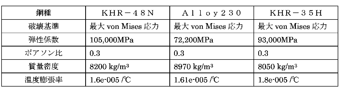
- Table 4 Various physical properties of each steel used for the analysis are shown in Table 4 below.
- the welded parts of the bend pipe and straight pipe (range from 10 to 30 mm from each end face abutted at the time of welding) are close to the pipe end face and lack of structural strength, and the material is weak due to heat received during welding It becomes a part which tends to cause a lack of strength especially during use due to the conversion. Therefore, these welded portions are formed thinner, more specifically, 1-2 mm thinner than other portions for the purpose of ensuring durability against severe thermal conditions from the combustion gas.
- a supported portion for welding the connecting piece of the bend pipe and the straight pipe is locally thick (eg, about 10 mm).
- the supported portions among the base end portions of the bend pipes 3A and 3C shown in FIG. 1, the portions facing each other in the vertical direction, the lower surface of the base end portion on the lower side of the bend pipe 3B, and the most This is the upper surface portion of the near straight pipe 2D.
- the bend pipe in the present invention connects a plurality of pipe sections for the purpose of adjusting the extending direction of the pipe, branching from one pipe to a plurality of pipes, or consolidating the plurality of pipes into one pipe. Therefore, it is only necessary to have a curved portion or a bent portion, and includes not only the U-shaped tube shown in FIG.
- All of the bend pipes 3A, 3B, 3C including the second bend pipe 3B relatively spaced from the burner 5 may be a thin cast body of 3 to 8 mm.
- Only the adjacent first bend pipe 3A may be a thin cast body of 3 to 8 mm.
- all the bend pipes 3A, 3B, and 3C may be thin cast bodies of 3 to 8 mm.
- the shape of the radiant tube 1 is not limited to the W-shape described above, and may be a trident type.
- the number of bend pipes and straight pipes constituting the radiant tube 1 is not limited to the above-described example, and if at least one bend pipe is provided in a part of the configuration, for example, a pair of straight pipes and a pair of straight pipes It is good also as a radiant tube of the U shape etc. comprised only with one bend pipe
Landscapes
- Engineering & Computer Science (AREA)
- Chemical & Material Sciences (AREA)
- Mechanical Engineering (AREA)
- General Engineering & Computer Science (AREA)
- Combustion & Propulsion (AREA)
- Organic Chemistry (AREA)
- Physics & Mathematics (AREA)
- Thermal Sciences (AREA)
- Chemical Kinetics & Catalysis (AREA)
- Inorganic Chemistry (AREA)
- Combustion Of Fluid Fuel (AREA)
- Gas Burners (AREA)
Abstract
Description
一対の直管どうしを接続する少なくとも一つのベンド管を備え、前記一対の直管の一方からバーナーの燃焼ガスが吹き込まれる耐熱金属製のラジアントチューブであって、
少なくとも前記バーナーに最も近接したベンド管として外径が150~210mmで肉厚が3~8mmの鋳造体が用いられている点にある。
また、バーナーに最も近接したベンド管の薄肉化によって、ラジアントチューブが全体として軽量化されるため、取替え工事に要する労力の負担も減少した。
また、ラジアントチューブ全体としての軽量化がさらに高められるため、取替え工事に要する労力の負担も更に減少した。
蓄熱体4を通過した排ガスは切り替え弁6及び排ガス処理装置(不図示)などを介して外気に放出することができる。
直管2とベンド管3との接続は、各管の端面どうしを付き合わせた状態で外周側から行う溶接によって実現されている。
バーナー5から比較的離間した第2ベンド管3B、及び、4つの直管2A,2B,2C,2Dとしては肉厚が5mmまたは10mmの鋳造体が用いられている。
尚、ここで用いている離間や近接という語句は、バーナー5から発されてラジアントチューブ1の内部を移動する火炎または燃焼ガスの経路上におけるバーナー5との距離の長短を意味する。
これは、鋳造による一体成形によるベンド管では、板材のプレス加工によって得られた左右の管体の端面どうしを管の軸芯に沿って溶接して得たベンド管などに比べて、肉厚がより均一となり、また、ベンド管の長手方向に延びた溶接部のような応力集中箇所もなくなるため、バーナーの燃焼ガスによる急激な温度上昇や急激な温度降下によるヒートクラックなどが生じ難くなるためと考えられる。
さらに、薄肉化されたことで、応力による変形が生じ易くなるので、熱応力を吸収し易くなり、バーナーの燃焼ガスによる急激な温度上昇によってもヒートクラックが生じ難くなったと考えられる。
また、ラジアントチューブ全体として軽量化されるため、取替え工事に要する労力の負担も減少した。
他方、3つのベンド管3A,3B,3Cはいずれも、溶融金属を注入後のキャビティ内を真空ポンプなどによって負圧化する吸引鋳造法を用いているので、薄肉化を実現しながらも、一般には溶融金属の凝固時に生じ易い引け巣や引け緩みが無く、表面の地肌も良好なベンド管が得られている。
尚、更なる軽量化などの目的で、直管においても吸引鋳造法を用いて薄肉化を図ってもよい。
このシミュレーションでは、リジェネレーティブ型としての使用を模して、一定の期間に亘って各バーナー5から燃焼ガスが交互に供給され、燃焼された。
表中に記したベンド管肉厚の数値は、3つのベンド管3A,3B,3Cの全てに適用されており、同様に、直管肉厚の数値は4つの直管2A,2B,2C,2Dの全てに適用されている。

ベンド管3の肉厚を8mm以下とすることで100MPaを上回る数値が確保できること、また、8mm以下よりも7mm以下が好ましく、6mm以下がさらに好ましく、ベンド管3の肉厚が薄いほど同数値が高くなる傾向がある。
また、最大応力の測定結果についても、同様に、ベンド管3の肉厚を8mm以下とすることで、55MPa以下の低い数値を確保できるという傾向がある。
但し、直管肉厚を5mmとした例においてベンド管0.2%耐力の測定値を見る限り、直管の肉厚がベンド管の肉厚を上回るラジアントチューブ1の方が高い数値を示す傾向が見られる。
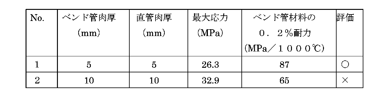

最大応力の測定結果についても、ベンド管3の肉厚が小さい方が低い数値が得られるという同様の傾向が得られている。
実施例1、2で行った第3ベンド管3Cが受けた熱応力に関する諸特性の解析では、SolidWorks社製ソフトウェア:SolidWorks Simulationを用い、モデルタイプとしては、バーナー入熱側端部2箇所(図1における直管2A,2Dの右側端部)を炉の壁面に完全拘束した状態での線形等方性弾性モデルを適用した。
解析に用いた各鋼材の諸物性を下記の表4に示す。
〈1〉バーナー5から比較的離間した第2ベンド管3Bも含めて、全てのベンド管3A,3B,3Cを3~8mmの薄肉鋳造体としてもよい。
3 ベンド管(3A,3C)
5 バーナー
Claims (6)
- 直管どうしを接続する少なくとも一つのベンド管を備え、前記直管の一方からバーナーの燃焼ガスが吹き込まれる耐熱金属製のラジアントチューブであって、
少なくとも前記バーナーに最も近接したベンド管として外径が150~210mmで肉厚が3~8mmの鋳造体が用いられていることを特徴とするラジアントチューブ。 - 前記ベンド管の前記直管との接続近傍部の肉厚が前記ベンド管の他の部位よりも薄くされていることを特徴とする請求項1に記載のラジアントチューブ。
- 前記ベンド管を複数備え、これら複数の前記ベンド管の全てについて肉厚が3~8mmの鋳造体が用いられていることを特徴とする請求項1または2に記載のラジアントチューブ。
- 前記直管の肉厚が7mm以下とされていることを特徴とする請求項1から3のいずれか一項に記載のラジアントチューブ。
- 前記直管の前記ベンド管との接続近傍部の肉厚が前記直管の他の部位よりも薄くされていることを特徴とする請求項1から4のいずれか一項に記載のラジアントチューブ。
- 前記直管として肉厚が前記ベンド管の肉厚を上回る鋳造体が用いられていることを特徴とする請求項1から5のいずれか一項に記載のラジアントチューブ。
Priority Applications (5)
| Application Number | Priority Date | Filing Date | Title |
|---|---|---|---|
| CA2831302A CA2831302A1 (en) | 2011-03-31 | 2012-03-28 | Radiant tube |
| KR1020137028753A KR20140045350A (ko) | 2011-03-31 | 2012-03-28 | 래디언트 튜브 |
| CN2012800135173A CN103429958A (zh) | 2011-03-31 | 2012-03-28 | 辐射管 |
| US14/008,078 US20140053826A1 (en) | 2011-03-31 | 2012-03-28 | Radiant tube |
| JP2013507676A JPWO2012133539A1 (ja) | 2011-03-31 | 2012-03-28 | ラジアントチューブ |
Applications Claiming Priority (2)
| Application Number | Priority Date | Filing Date | Title |
|---|---|---|---|
| JP2011079964 | 2011-03-31 | ||
| JP2011-079964 | 2011-03-31 |
Publications (1)
| Publication Number | Publication Date |
|---|---|
| WO2012133539A1 true WO2012133539A1 (ja) | 2012-10-04 |
Family
ID=46931247
Family Applications (1)
| Application Number | Title | Priority Date | Filing Date |
|---|---|---|---|
| PCT/JP2012/058158 Ceased WO2012133539A1 (ja) | 2011-03-31 | 2012-03-28 | ラジアントチューブ |
Country Status (6)
| Country | Link |
|---|---|
| US (1) | US20140053826A1 (ja) |
| JP (1) | JPWO2012133539A1 (ja) |
| KR (1) | KR20140045350A (ja) |
| CN (1) | CN103429958A (ja) |
| CA (1) | CA2831302A1 (ja) |
| WO (1) | WO2012133539A1 (ja) |
Cited By (1)
| Publication number | Priority date | Publication date | Assignee | Title |
|---|---|---|---|---|
| US10246454B2 (en) | 2013-01-17 | 2019-04-02 | Janssen Pharmaceutica Nv | Substituted 3,4-dihydro-2H-pyrido[1,2-a]pyrazine-1,6-diones as gamma secretase modulators |
Families Citing this family (1)
| Publication number | Priority date | Publication date | Assignee | Title |
|---|---|---|---|---|
| CN103747546A (zh) * | 2014-01-17 | 2014-04-23 | 华能无锡电热器材有限公司 | U型电加热管 |
Citations (5)
| Publication number | Priority date | Publication date | Assignee | Title |
|---|---|---|---|---|
| JPS60169255U (ja) * | 1984-04-16 | 1985-11-09 | 新日本製鐵株式会社 | 輻射管の支持構造 |
| JPH02152190A (ja) * | 1988-12-01 | 1990-06-12 | Kanthal:Ab | 放熱管 |
| JPH04293748A (ja) * | 1991-03-22 | 1992-10-19 | Kubota Corp | ラジアントチューブ用耐熱合金 |
| JPH05285533A (ja) * | 1992-04-13 | 1993-11-02 | Kubota Corp | ラジアントチューブの直管部の製造方法 |
| JP2003065503A (ja) * | 2001-08-21 | 2003-03-05 | Osaka Gas Co Ltd | ラジアントチューブ |
Family Cites Families (9)
| Publication number | Priority date | Publication date | Assignee | Title |
|---|---|---|---|---|
| US489827A (en) * | 1893-01-10 | Loco moti ve-boiler | ||
| US984652A (en) * | 1910-02-12 | 1911-02-21 | Locomotive Superheater Co | Method of making u-shaped pipe-bends. |
| US4878480A (en) * | 1988-07-26 | 1989-11-07 | Gas Research Institute | Radiant tube fired with two bidirectional burners |
| JP2765353B2 (ja) * | 1992-03-06 | 1998-06-11 | 住友金属工業株式会社 | ラジアントチューブ型加熱装置における燃焼方法 |
| US20070054227A1 (en) * | 2003-02-25 | 2007-03-08 | Takeshi Tada | Alternate combustion type regenerative radiant tube burner apparatus |
| US20100044023A1 (en) * | 2008-08-21 | 2010-02-25 | Andres Alberto Canales | Heat exchanger systems & fabrication methods |
| CN101724744B (zh) * | 2009-12-18 | 2011-07-06 | 孙立彬 | 双p型辐射管及其制造方法 |
| WO2011163654A1 (en) * | 2010-06-25 | 2011-12-29 | Arcelormittal Investigacion Y Desarrollo, S.L. | Nickel-base radiant tube and method for making the same |
| PL2676093T3 (pl) * | 2011-02-14 | 2019-01-31 | Massimiliano BISSON | Rurowy element promiennikowy dla urządzeń przemysłowych, jego zastosowanie i sposób obróbki cieplnej |
-
2012
- 2012-03-28 JP JP2013507676A patent/JPWO2012133539A1/ja active Pending
- 2012-03-28 WO PCT/JP2012/058158 patent/WO2012133539A1/ja not_active Ceased
- 2012-03-28 CA CA2831302A patent/CA2831302A1/en not_active Abandoned
- 2012-03-28 KR KR1020137028753A patent/KR20140045350A/ko not_active Withdrawn
- 2012-03-28 US US14/008,078 patent/US20140053826A1/en not_active Abandoned
- 2012-03-28 CN CN2012800135173A patent/CN103429958A/zh active Pending
Patent Citations (5)
| Publication number | Priority date | Publication date | Assignee | Title |
|---|---|---|---|---|
| JPS60169255U (ja) * | 1984-04-16 | 1985-11-09 | 新日本製鐵株式会社 | 輻射管の支持構造 |
| JPH02152190A (ja) * | 1988-12-01 | 1990-06-12 | Kanthal:Ab | 放熱管 |
| JPH04293748A (ja) * | 1991-03-22 | 1992-10-19 | Kubota Corp | ラジアントチューブ用耐熱合金 |
| JPH05285533A (ja) * | 1992-04-13 | 1993-11-02 | Kubota Corp | ラジアントチューブの直管部の製造方法 |
| JP2003065503A (ja) * | 2001-08-21 | 2003-03-05 | Osaka Gas Co Ltd | ラジアントチューブ |
Cited By (1)
| Publication number | Priority date | Publication date | Assignee | Title |
|---|---|---|---|---|
| US10246454B2 (en) | 2013-01-17 | 2019-04-02 | Janssen Pharmaceutica Nv | Substituted 3,4-dihydro-2H-pyrido[1,2-a]pyrazine-1,6-diones as gamma secretase modulators |
Also Published As
| Publication number | Publication date |
|---|---|
| US20140053826A1 (en) | 2014-02-27 |
| JPWO2012133539A1 (ja) | 2014-07-28 |
| CN103429958A (zh) | 2013-12-04 |
| CA2831302A1 (en) | 2012-10-04 |
| KR20140045350A (ko) | 2014-04-16 |
Similar Documents
| Publication | Publication Date | Title |
|---|---|---|
| CN101379345A (zh) | 锅炉水冷壁用板 | |
| CN104114730A (zh) | 双层管及使用其的焊接结构体 | |
| CN105066098A (zh) | 超620℃蒸汽参数超超临界机组锅炉的集箱 | |
| JPWO2012133539A1 (ja) | ラジアントチューブ | |
| CN103649664A (zh) | 用于工厂等的辐射管状元件 | |
| JP6640461B2 (ja) | マルチホールプラグ | |
| CN110073162A (zh) | 用于炼钢炉的延伸腿回弯头及其方法 | |
| JP6323366B2 (ja) | ラジアントチューブ | |
| JP2015528888A (ja) | 溶解炉のための冷却要素 | |
| JP5348713B2 (ja) | 浸漬管 | |
| JP2014119212A (ja) | 熱交換器 | |
| JP6025561B2 (ja) | 伝熱管の振動抑制装置及び当該振動抑制装置の補修方法 | |
| CN207243951U (zh) | 退火炉 | |
| CN110088550B (zh) | 喷枪管 | |
| CN200974851Y (zh) | 炉辊 | |
| CN224001447U (zh) | 风口小套和高炉风口装置 | |
| JP7838526B2 (ja) | シャフト型電気炉 | |
| JP5622323B2 (ja) | 熱交換器 | |
| KR100858981B1 (ko) | 초임계 압력 석탄 보일러 고성능 버너 장치 | |
| KR102415823B1 (ko) | 순환유동층연소 보일러용 과열기 | |
| JP3721030B2 (ja) | リジェネバーナ | |
| CN212430898U (zh) | 一种锅炉高温区吹灰器头部套管 | |
| KR200419882Y1 (ko) | 화장로용 관받침대 | |
| JP3323416B2 (ja) | 熱処理炉のラジアントチューブ | |
| JP3684475B2 (ja) | フェライト系耐熱鋼管の溶接構造 |
Legal Events
| Date | Code | Title | Description |
|---|---|---|---|
| 121 | Ep: the epo has been informed by wipo that ep was designated in this application |
Ref document number: 12763171 Country of ref document: EP Kind code of ref document: A1 |
|
| ENP | Entry into the national phase |
Ref document number: 2013507676 Country of ref document: JP Kind code of ref document: A |
|
| ENP | Entry into the national phase |
Ref document number: 2831302 Country of ref document: CA |
|
| NENP | Non-entry into the national phase |
Ref country code: DE |
|
| ENP | Entry into the national phase |
Ref document number: 20137028753 Country of ref document: KR Kind code of ref document: A |
|
| WWE | Wipo information: entry into national phase |
Ref document number: 14008078 Country of ref document: US |
|
| 122 | Ep: pct application non-entry in european phase |
Ref document number: 12763171 Country of ref document: EP Kind code of ref document: A1 |