WO2012133451A1 - 撮像レンズユニットの製造方法、及び、撮像レンズユニット - Google Patents
撮像レンズユニットの製造方法、及び、撮像レンズユニット Download PDFInfo
- Publication number
- WO2012133451A1 WO2012133451A1 PCT/JP2012/057997 JP2012057997W WO2012133451A1 WO 2012133451 A1 WO2012133451 A1 WO 2012133451A1 JP 2012057997 W JP2012057997 W JP 2012057997W WO 2012133451 A1 WO2012133451 A1 WO 2012133451A1
- Authority
- WO
- WIPO (PCT)
- Prior art keywords
- lens
- resin
- lens unit
- holder member
- optical surface
- Prior art date
- Legal status (The legal status is an assumption and is not a legal conclusion. Google has not performed a legal analysis and makes no representation as to the accuracy of the status listed.)
- Ceased
Links
Images






Classifications
-
- G—PHYSICS
- G02—OPTICS
- G02B—OPTICAL ELEMENTS, SYSTEMS OR APPARATUS
- G02B7/00—Mountings, adjusting means, or light-tight connections, for optical elements
- G02B7/02—Mountings, adjusting means, or light-tight connections, for optical elements for lenses
-
- G—PHYSICS
- G02—OPTICS
- G02B—OPTICAL ELEMENTS, SYSTEMS OR APPARATUS
- G02B7/00—Mountings, adjusting means, or light-tight connections, for optical elements
- G02B7/02—Mountings, adjusting means, or light-tight connections, for optical elements for lenses
- G02B7/021—Mountings, adjusting means, or light-tight connections, for optical elements for lenses for more than one lens
-
- B—PERFORMING OPERATIONS; TRANSPORTING
- B29—WORKING OF PLASTICS; WORKING OF SUBSTANCES IN A PLASTIC STATE IN GENERAL
- B29D—PRODUCING PARTICULAR ARTICLES FROM PLASTICS OR FROM SUBSTANCES IN A PLASTIC STATE
- B29D11/00—Producing optical elements, e.g. lenses or prisms
- B29D11/0074—Production of other optical elements not provided for in B29D11/00009- B29D11/0073
-
- G—PHYSICS
- G02—OPTICS
- G02B—OPTICAL ELEMENTS, SYSTEMS OR APPARATUS
- G02B13/00—Optical objectives specially designed for the purposes specified below
- G02B13/001—Miniaturised objectives for electronic devices, e.g. portable telephones, webcams, PDAs, small digital cameras
- G02B13/0015—Miniaturised objectives for electronic devices, e.g. portable telephones, webcams, PDAs, small digital cameras characterised by the lens design
- G02B13/002—Miniaturised objectives for electronic devices, e.g. portable telephones, webcams, PDAs, small digital cameras characterised by the lens design having at least one aspherical surface
- G02B13/003—Miniaturised objectives for electronic devices, e.g. portable telephones, webcams, PDAs, small digital cameras characterised by the lens design having at least one aspherical surface having two lenses
-
- G—PHYSICS
- G02—OPTICS
- G02B—OPTICAL ELEMENTS, SYSTEMS OR APPARATUS
- G02B7/00—Mountings, adjusting means, or light-tight connections, for optical elements
- G02B7/02—Mountings, adjusting means, or light-tight connections, for optical elements for lenses
- G02B7/023—Mountings, adjusting means, or light-tight connections, for optical elements for lenses permitting adjustment
Definitions
- the present invention relates to a method for manufacturing an imaging lens unit in which a lens is incorporated in a holder, and an imaging lens unit.
- An imaging lens unit incorporated in a cellular phone or the like has a structure in which a periphery of an optical lens for image formation is held by a holder.
- the assembly of the optical lens to the holder is very precise in positioning accuracy, and is usually performed by an automatic assembly system incorporating an image recognition technique.
- an automatic assembly system incorporating an image recognition technique is very expensive and requires a very large site because the production line is composed of the process of inserting the lens into the holder and the process of bonding the lens to the holder.
- the replacement of the equipment performed every time the lens type is changed becomes very large and requires a lot of man-hours.
- Patent Document 1 it is necessary to provide a resin restricting member in contact with the peripheral portion of the optical surface exposed by the opening in the molding die so that the resin does not flow into the portion corresponding to the opening of the holder. is there.
- the pressing force of such a resin limiting member is insufficient, the resin flows into the optical surface. Therefore, it is necessary to bring the resin limiting member into contact with the lens with a pressing force larger than a predetermined value.
- the pressing force of the resin limiting member is too large, there is a problem that the optical glass lens is deformed or broken, and therefore the pressing force of the resin limiting member needs to be adjusted appropriately.
- the resin restricting member may cause the plastic lens to sink into the contact portion of the plastic lens with a slight stress. It has been found that this affects the optical surface. In particular, when a holder is molded using a resin melted by heat, it is considered that the plastic lens is softened under the influence of heat during the molding of the holder, and the above problem is remarkably generated. It has also been found that this problem also occurs when the plastic lens is made of an energy curable resin such as a photocurable resin or a thermosetting resin.
- the present invention has been made in view of the above problems of the background art, and is an imaging lens unit that molds a holder together with a lens, and a method for manufacturing an imaging lens unit that can suppress deformation of the lens due to molding of the holder.
- the purpose is to provide.
- Another object of the present invention is to provide an imaging lens unit that suppresses deformation of the lens due to molding of the holder.
- a lens including at least a part of a resin is positioned and disposed in a mold having a molding space for molding at least a part of a holder member. Generated by forming the holder member by filling the resin inside and solidifying it, forming a holder member that integrally holds the lens inside, and heat-treating the lens held by the holder member Releasing the distortion of the lens.
- the resin holder member that positions and holds the lens inside.
- the surface of the lens is deformed by the mold, and there is a possibility that distortion that affects the optical surface of the lens may remain in the lens.
- the above-described distortion may be caused by heating the lens and the holder member. Since it can be released, the optical surface of the lens can be returned to the original optical accuracy. That is, an imaging lens unit that suppresses deformation of the lens due to molding of the holder member can be provided by returning the lens even when it is deformed during molding of the holder member.
- the lens in the manufacturing method, is a composite lens including a substrate and a lens layer, and the lens layer is made of resin.
- the lens layer is deformed when the holder member is molded, but the lens layer can be restored to the original state before the deformation by heat-treating the lens and the holder member.
- the lens is a combined lens in which a plurality of lens elements are integrated, and at least one of the plurality of lens elements is made of resin.
- at least one lens element is deformed when the holder member is molded, but the lens element can be restored to its original state before the deformation by heat-treating the lens and the holder member.
- the lens is formed using an energy curable resin.
- the deformation of the lens by the mold is confined as distortion in the energy curable resin constituting the lens by molding of the holder member, but can be released by heat treatment.
- the lens is formed using a thermoplastic resin.
- the deformation of the lens by the mold is confined as distortion in the thermoplastic resin constituting the lens by molding the holder member, but can be released by heat treatment.
- the holder member is formed of at least one of an LCP (Liquid Crystal Polymer) resin and a PPA (Polyphthalamide) resin. In this case, it becomes easy to process the imaging lens unit in the reflow process.
- LCP Liquid Crystal Polymer
- PPA Polyphthalamide
- the mold has at least one abutting member that prevents the resin from flowing into at least one optical surface provided on the surface of the lens.
- distortion may remain on the optical surface of the lens by the contact member, but the optical surface of the lens can be returned to a substantially original state by heat treatment of the lens and the holder member.
- At least one contact member contacts the outside of the optical surface while avoiding the optical surface.
- the outside of the optical surface is deformed, and this deformation may cause distortion on the optical surface of the lens, but the generated distortion can be released by heat treatment.
- the at least one contact member has substantially the same shape as the optical surface and contacts the optical surface.
- the contact member may cause distortion directly on the optical surface of the lens.
- the heat treatment is at least a lower limit temperature that is 20 ° C. lower than the load deflection temperature of the resin portion of the lens (ISO75A method), and an upper limit temperature that is the decomposition temperature or melting point of the resin portion of the lens. In a lower temperature range.
- the lens can be softened to such an extent that the distortion of the lens can be released, and damage to the lens due to excessive softening can be prevented.
- the heat treatment is performed in a temperature range of 260 ° C. or lower, which is the upper limit of the use environment temperature of the lens. In this case, it is possible to reliably prevent the lens from being damaged.
- the load deflection temperature of the holder member is higher than the load deflection temperature of the resin portion of the lens. In this case, distortion of the lens can be released while preventing deformation of the holder member.
- a resin body constituting a part of the holder is placed in the mold, and the resin is filled in the mold and solidified. Then, the solidified resin and the resin body are joined to form a holder member.
- An imaging lens unit is formed by solidifying or curing a lens having a first optical surface and a second optical surface, and supplying resin around the lens in a state where the lens is disposed in a mold. And a holder member that integrally holds the lens therein, and the lens is heat-treated while being held by the holder member.
- the lens surface may be deformed by the mold when forming a holder member that integrally holds the lens inside, and distortion that may affect the optical surface of the lens may remain in the lens.
- the optical surface of the lens can be returned to or brought close to the original optical accuracy, and the lens by molding the holder member It is possible to provide an imaging lens unit that suppresses deformation of the lens.
- the lens in the imaging lens unit, is abutted on the mold to prevent the resin from flowing into at least one of the first optical surface and the second optical surface.
- the contact mark has returned to a substantially flat state by the heat treatment, and the optical surface of the lens has returned to the original optical accuracy.
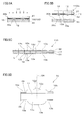
- FIG. 1A is a side sectional view showing the structure of the imaging lens unit according to the first embodiment
- FIG. 1B is a perspective view of the imaging lens unit
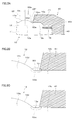
- 2A and 2B are partially enlarged sectional views for explaining deterioration of the optical surface of the lens due to molding of the holder member
- FIG. 2C is a partially enlarged sectional view for explaining restoration of the optical surface and the like.
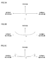
- 3A is a diagram for explaining the initial shape accuracy of the lens
- FIG. 3B is a diagram for explaining the shape accuracy of the lens after being incorporated into the holder member
- FIG. 3C is a shape of the lens after the heat treatment. It is a figure explaining accuracy. It is a flowchart explaining the manufacture procedure of the imaging lens unit shown in FIG.
- FIGS. 5A to 5D are diagrams for explaining a lens manufacturing process. It is a figure explaining a part of manufacturing process of an imaging lens unit.
- FIG. 7A is a cross-sectional view illustrating the formation of the cavity in the manufacturing apparatus
- FIG. 7B is a cross-sectional view illustrating the formation of the holder member.
- FIG. 8A is a cross-sectional view illustrating mold opening in the manufacturing apparatus
- FIG. 8B is a cross-sectional view illustrating removal of the imaging lens unit. It is a figure explaining the thermostat for heat processing.
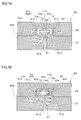
- 11A and 11B are cross-sectional views illustrating an imaging lens unit and a manufacturing method thereof according to the third embodiment.
- 12A and 12B are cross-sectional views illustrating an imaging lens unit and a manufacturing method thereof according to the fourth embodiment.
- the imaging lens unit 100 includes a lens 10 as an optical function unit housed therein, and a case-like holder member 40 that holds the lens 10 from the periphery.
- the lens 10 is, for example, cut out by dicing from a lens wafer (wafer-like base material) on which a large number of lenses are arranged.
- the lens 10 has a rectangular outline in plan view, and has a quadrangular prism side surface.
- the lens 10 is a compound lens having a structure in which a glass substrate 11 is sandwiched between a first lens layer 12 and a second lens layer 13 made of resin.
- the glass substrate 11 is a flat plate having optical transparency.
- the glass substrate 11 is not limited to glass but can be replaced with a substrate formed of a resin material or the like. Further, the glass substrate 11 can be provided with a function such as an IR cut filter (infrared cut filter).
- the first lens layer 12 has a circular contour lens main body portion 12a provided in the central portion around the optical axis OA, and a square contour frame portion 12b extending around the lens main body portion 12a.
- the lens body 12a is an aspherical lens, for example, and has a first optical surface 12d on the exposed front side.
- the first optical surface 12d and the outer first frame surface 10a are the first surface of the lens 10.
- the first lens layer 12 is made of a curable resin having reflow heat resistance, for example. Examples of the curable resin include a thermosetting resin, a photocurable resin, and a radiation curable resin.
- the second lens layer 13 also has a circular contour lens main body portion 13a provided in the central portion around the optical axis OA and a square contour frame portion 13b extending around the lens main body portion 13a.
- the lens body 13a is an aspherical lens, for example, and has a second optical surface 13e on the exposed front side.
- the second optical surface 13e and the second frame surface 10b outside thereof are the second surface of the lens 10.
- the second lens layer 13 is made of, for example, a curable resin having reflow heat resistance.
- first lens layer 12 and the second lens layer 13 may be formed of a thermoplastic resin instead of the curable resin. However, in this case, it is desirable that the first lens layer 12 and the second lens layer 13 be thermally stable during the molding of the holder member 40 described later, and have thermal characteristics that are not easily softened by the heat during the molding of the holder. It is desirable to have.
- a first diaphragm 15 is provided between the glass substrate 11 and the first lens layer 12.
- a second diaphragm 16 is provided between the glass substrate 11 and the second lens layer 13.
- These diaphragms 15 and 16 do not interfere with the second optical surface 13e on the second lens layer 13 side and the like, and have a ring-shaped member having openings having shapes along the edges of the openings OP1 and OP2 of the holder member 40. It is.
- the diaphragms 15 and 16 are made of, for example, a metal film or a light-shielding resin film. As the light-shielding resin film, black paint or black photoresist can be used.
- the holder member 40 for housing the lens 10 is made of a heat-resistant resin that can withstand at least the heat treatment described later.
- the holder member 40 is preferably made of, for example, a thermoplastic resin having reflow heat resistance (for example, LCP, PPA, etc.).
- the holder member 40 includes a top portion 41 having a square plate-like contour, a bottom portion 42 having a square plate-like contour, and a side wall portion 43 having a square cylindrical contour.
- a rectangular columnar storage space HS for fitting and holding the lens 10 is formed inside the holder member 40.
- the holder member 40 is integrally formed by resin injection molding and formed as an integral single member.
- the imaging lens unit 100 having heat resistance can be processed in the reflow process.
- the upper part 41 of the holder member 40 faces the first frame surface 10a on the upper side of the lens 10 held in the storage space HS and restricts the upward movement of the lens 10 along the optical axis OA. .
- the bottom portion 42 faces the second frame surface 10b on the lower side of the lens 10 and restricts the downward movement of the lens 10 along the optical axis OA.
- the side wall portion 43 faces the four side surfaces 10 c of the lens 10 and restricts movement in the lateral direction perpendicular to the optical axis OA of the lens 10.
- a circular opening OP1 is formed in the center of the upper portion 41.
- the annular edge 40i surrounding the opening OP1 is arranged so as to shield the periphery of the first optical surface 12d of the lens 10, thereby functioning as a kind of stop.
- a circular opening OP2 is formed at the center of the bottom portion.
- the annular edge portion 40j surrounding the opening OP2 is arranged so as to shield the periphery of the second optical surface 13e of the lens 10, thereby functioning as a kind of stop.
- the surface excluding is in contact with the liquid resin before solidification.
- the resin is solidified, for example, the inner surface 40e of the upper portion 41 of the holder member 40 is attached to the first frame surface 10a of the lens 10. Further, the inner surface 40f of the bottom portion 42 is attached to the second frame surface 10b of the lens 10.
- the surface of the lens 10 is made of resin.
- first frame surface 10a of the lens 10 and the inner surface 40e of the upper portion 41 of the holder member 40 are affected by the heat generated during the injection molding of the holder member 40.
- the surface of the frame surface 10a is softened and firmly joined to each other by welding, and is directly joined without using an adhesive.
- the second frame surface 10b of the lens 10, the inner surface 40f of the bottom portion 42 of the holder member 40, and the side surface 10c of the lens 10 and the inner surface 40g of the side wall portion 43 of the holder member 40 are used without using an adhesive. Directly joined.
- the imaging lens unit 100 having such a configuration, since the holder member 40 is in close contact with the periphery of the lens 10 without a gap, it is possible to prevent the occurrence of ghost and flare due to the incidence of light from the lens side surface. . Further, since there is no unnecessary gap on the side surface 10c of the lens 10, the imaging lens unit 100 is downsized, and it is easy to satisfy the appearance specifications required when it is assumed to be mounted on a final product such as an imaging device. Deterioration of dimensional accuracy due to deformation at the time of mold release like a conventional holder is also suppressed.
- the lens 10 is a compound lens, but the entire lens 10 may be formed of a single resin material.
- the deterioration of the first optical surface 12d of the lens 10 will be described with reference to FIGS. 2A and 2B. Since the holder member 40 is integrally molded by resin injection molding as described above, the narrow annular boundary portion 10m between the first optical surface 12d of the lens 10 and the first frame surface 10a is not molded. Further, the end face 62e at the tip of the fixing member 62d extending from the molding die 52 comes into contact.
- the fixing member 62d is indispensable because it prevents the flowing resin from flowing into the first optical surface 12d side. From the viewpoint of preventing resin leakage, the fixing member 62d is moved to the boundary portion 10m with a predetermined pressure or more.
- a shallow recess 12r that is depressed in the boundary portion 10m is formed.
- the depression 12r is lower by several ⁇ m to several tens of ⁇ m than the original surface level SO, and forms a step with the periphery.
- the depression 12r itself is outside the first optical surface 12d and does not directly affect the performance of the lens 10.
- the inventors' investigation has revealed that the generation of the recess 12r affects the shape accuracy of the first optical surface 12d, that is, the optical accuracy.
- the shape accuracy of the first optical surface 12d is deteriorated by enclosing the lens 10 in the holder member 40, and the shape accuracy of the first optical surface 12d adjacent to the first optical surface 12d is significantly deteriorated as the recess 12r becomes deeper.
- the deterioration of the shape accuracy of the first optical surface 12d may be allowed depending on the specifications of the imaging lens unit 100, but in view of the fact that the level of optical specifications required for the imaging lens unit 100 is increasing. It is desirable to suppress the deformation of the first optical surface 12d as much as possible.
- the depression 12r as described above can be made somewhat shallower by lowering the resin temperature or the mold temperature, the fluidity of the resin at the time of injection molding is lowered, and another problem such as an appearance defect of the holder member 40 is caused. Since a problem occurs, it is difficult to prevent deterioration of the shape accuracy of the optical surface by lowering the resin temperature and the mold temperature.
- the reason why the shape accuracy of the first optical surface 12d deteriorates when the recess 12r is deepened is that the heated first lens layer 12 is bounded by the pressing force from the end surface 62e of the fixing member 62d of the mold 52 for injection molding. This is considered to be because the elastic deformation occurs at 10 m, the deformation also expands around the boundary 10 m due to the stress, and the first optical surface 12 d of the lens body 12 a is deformed as a whole. Such deformation remains as a minute shape change of the recess 12r of the boundary portion 10m and the first optical surface 12d even after the molded product is taken out from the mold as the imaging lens unit 100 after the holder is molded.
- the first lens layer 12 is temporarily exposed to a high temperature during the injection molding of the holder member 40 and gradually cooled. However, even if the first lens layer 12 is taken out from the mold 52 after cooling, it corresponds to the tip shape of the fixing member 62d.
- the depression 12r remains, and the shape change in the depression 12r diffuses and remains as a minute shape change of the first optical surface 12d.
- the minute shape change of the first optical surface 12d is a deformation due to stress from the mold 52 remaining as a history. Therefore, by applying heat to the imaging lens unit 100 obtained by molding the holder, the first lens layer 12 is flattened based on the recess 12r formed in the boundary portion 10m as shown in FIG. 2C. It is considered that by returning to the fine mark 12s, the minute shape change of the first optical surface 12d is also eliminated, and the first optical surface 12d having the original shape accuracy is restored.
- the obtained imaging lens unit 100 is heated for a certain period of time or more, so that the boundary portion 10m of the first lens layer 12 and distortion in the vicinity thereof are reduced. Decided to release.
- FIG. 3A shows the state of the first optical surface 12d of the lens 10 before molding the holder member 40
- the vertical axis shows the shape aberration of the first optical surface 12d
- the horizontal axis shows the first optical surface 12d.
- the distance or position from the optical axis OA is shown.
- the first optical surface 12d is almost free of aberrations.
- FIG. 3B shows a state of the first optical surface 12d of the lens 10 immediately after the holder member 40 is molded.
- the first optical surface 12d has an aberration that increases sharply particularly in the peripheral portion.
- 3C shows a state of the first optical surface 12d of the lens 10 after the imaging lens unit 100 is subjected to a heat treatment for a predetermined time or longer.
- the first optical surface 12d is in a state of almost no aberration as in the original.
- a dashed-dotted line shows the state before performing heat processing for reference.
- the recess 12r is relatively conspicuous in the boundary portion 10m as shown in FIG. 2B before the heat treatment, but after the heat treatment, the boundary is shown in FIG. 2C. At the position of the portion 10m, it was a flat mark 12s close to the original shape.
- the second optical surface 13e is similarly deformed by the injection molding of the holder member 40.
- the deformation of the second optical surface 13e can also be substantially eliminated by the heat treatment as described above. Therefore, the shape accuracy of the second optical surface 13e can be recovered.
- the optical performance of the lens 10 can be returned to the original state by heat-treating the imaging lens unit 100.
- the heat treatment for releasing the distortion of the lens 10 is performed in consideration of the thermal characteristics of the first lens layer 12 and the second lens layer 13 constituting the lens 10. Specifically, the heat treatment is at least a lower limit temperature that is 20 ° C. lower than the load deflection temperature of the resin material constituting the first and second lens layers 12, 13, and the first lens layer 12 and the second lens layer 13. In the temperature range lower than the upper limit temperature which is the decomposition temperature or melting point of the resin part.
- the load deflection temperature is given by the ISO75 A method.
- the lower than the higher load deflection temperature is set as the lower limit temperature
- the lower decomposition temperature or melting point is set as the upper limit temperature.
- the heat treatment for releasing the distortion of the lens 10 is performed in a temperature range of 260 ° C. or lower which is the upper limit of the use environment temperature of the lens 10.
- the lens 10 incorporated in the imaging lens unit 100 has an upper limit of 260 ° C. due to its specifications, but the lens 10 is subjected to heat treatment within a temperature range of 260 ° C. or less, which is the upper limit. It is possible to more reliably prevent the performance of the apparatus from deteriorating.
- the heat treatment is preferably performed at a temperature higher than the load deflection temperature of the lens resin in order to release the distortion of the lens 10 more easily and sufficiently.
- the heat treatment for releasing the distortion of the lens 10 needs to be performed in consideration of the thermal characteristics of the holder member 40. That is, the heat treatment is performed at a temperature lower than the heat resistance temperature of the resin constituting the holder member 40 (decomposition temperature or melting point, usually the lower one of the decomposition temperature and melting point).
- the resin constituting the holder member 40 a resin whose load deflection temperature is higher than the load deflection temperatures of the first and second lens layers 12 and 13 of the lens 10 may be used. preferable.
- the former is higher than the latter, the dimensional stability of the holder member accompanying the heat treatment increases, and the setting of the heat treatment temperature is less restricted.
- the former is higher than the latter by 50 ° C. or more.
- the load deflection temperature of the resin that constitutes the holder member 40 is higher than the load deflection temperature of the resin that constitutes the first and second lens layers 12 and 13 of the lens 10
- the lower limit temperature of the heat treatment is, as a result, Only the load deflection temperature of the first and second lens layers 12 and 13 need to be considered.
- An imaging unit having good performance can be obtained by performing reflow processing on the imaging lens unit that satisfies the prescribed optical performance and mounting the imaging device.
- the wafer lens 110 is formed by the shape transfer process shown in FIGS. 5A to 5C (step S11 in FIG. 4).
- a resin material 132 is applied on the transfer mold 30, and the transfer mold 30 is pressed against the front surface of the glass substrate 31 so as to have an appropriate interval. Thereafter, the resin material 132 sandwiched therebetween is cured by irradiating ultraviolet rays with a UV generator (not shown). Thereby, the transfer surfaces 30a and 30b of the transfer mold 30 are transferred to the resin material 132, and a large number of first surfaces (the first optical surface 12d of the first lens layer 12 shown in FIG. A first frame surface 10a) is formed. Thereby, the 1st resin layer 32 comprised including many 1st lens layers 12 is formed. A metal film or a resin film is formed (or attached) in advance as the diaphragm 15 on the front surface of the glass substrate 31.
- the first resin layer 32 and the glass substrate 31 are released from the transfer mold 30 as a unit, and an intermediate 110m to be the wafer lens 110 is produced.
- the same processing as the resin supply and mold surface transfer shown in FIG. 5A is also performed on the back surface of the glass substrate 11 of the intermediate body 110m, and the wafer lens 110 as shown in FIG. 5C is manufactured. That is, the second resin layer 33 of the wafer lens 110 is formed in the same manner as the first resin layer 32.
- the second resin layer 33 has a number of second surfaces each including the second optical surface 13e and the second frame surface 10b of the second lens layer 13 shown in FIG. 1A.
- a post-cure process is performed using a vacuum oven (not shown) at 100 to 200 ° C. for 30 minutes to 1 hour (step S12 in FIG. 4).
- a vacuum oven not shown
- the curing reaction of the first resin layer 32 and the second resin layer 33 can be made more complete, and the first resin layer 32 and the second resin layer 33 are formed of, for example, an epoxy resin or the like If done, the curing time can be shortened.
- step S13 in FIG. 4 a description will be given of a process for forming an optical functional film on the surface of the wafer lens 110 using a film forming apparatus (not shown) (step S13 in FIG. 4).
- the optical functional film include an antireflection film and a protective film. This film forming process may be omitted depending on the specifications of the lens 10.
- the lens 10 shown in FIG. 1A and the like is taken out by cutting the wafer lens 110 subjected to film formation by the above method into individual elements by dicing (cutting) as shown by a one-dot chain line L in FIG. 4 step S14).
- the holder member 40 that holds the lens 10 is formed around the lens 10 (steps S15 to S18 in FIG. 4). That is, the lens 10 is positioned and arranged in a mold having a molding space for molding the holder member, and the lens 10 is integrally held inside by filling the molding space with resin and solidifying it.
- the holder member 40 to be formed is formed.
- a method of forming a holder that integrally holds a lens by filling a resin in the molding space after the lens is arranged in a mold having a molding space for molding the holder member as described above. Will be referred to as insert molding.
- the second mold 52 is brought into a retracted state. Both molds 51 and 52 are opened, and the insert jig 70 holding the lens 10 is moved to a position above the first molding part 61 provided in the first mold 51.
- the first molding part 61 which is the movement destination of the insert jig 70, is provided so as to protrude from the parting surface 51 a of the first mold 51.
- a second molding portion 62 is provided opposite to the first molding portion 61 so as to be recessed from the parting surface 52a on the second mold 52 side.
- At least one of the molds 51 and 52 is provided with a resin injection port (not shown).
- a heating mechanism for heating the molds 51 and 52 and a platen for pressing the molds 51 and 52 from the back are provided, but the illustration is omitted for easy understanding. Yes.
- the insert jig 70 is an annular member, and temporarily holds the lens 10 in the central through hole 71.
- the insert jig 70 is driven remotely by a control drive device (not shown) and conveys the lens 10.
- the insert jig 70 incorporates a fluid-driven chuck member 72 having a plurality of pressing members that advance and retract toward the side surface 10 c of the lens 10.
- the insert jig 70 can support the lens 10 at the center of the through hole 71 in the illustrated set state by pressing the side surface 10c of the lens 10 from a plurality of directions.
- the lens 10 can be moved in the direction of the optical axis OA.
- An annular fitting surface 73 a having a taper for fitting with the first mold 51 is provided at the lower part of the insert jig 70.
- the insert jig 70 is lowered onto the first mold 51 so that the fitting surface 73a on the lower inner side of the insert jig 70 is tapered on the first molding portion 61 and the fitting member 61g is erected.
- the fitting surface 61f is fitted.
- the optical axis OA of the lens 10 held by the insert jig 70 and the axis AX of the first molding part 61 of the first mold 51 can be substantially matched.
- the lens 10 is supported on the cylindrical holding member 61d erected on the bottom of the first molding portion 61 and positioned in the lateral direction. That is, the holding member 61d is also a positioning member for precisely positioning the lens 10 in the direction perpendicular to the optical axis OA. Further, the holding member 61d also functions as a contact member that prevents the resin from flowing into the second optical surface 13e of the lens 10. That is, the holding member 61d also has a role of preventing the flowing resin MP from flowing into the space S1 adjacent to the second optical surface 13e of the lens 10 during molding described later.
- the support of the lens 10 by the holding member 61d is performed on the outer peripheral side of the upper surface of the holding member 61d.
- the outer side of the second optical surface 13e of the second lens layer 13 specifically, the annular region of the second frame surface 10b close to the boundary with the second optical surface 13e contacts the end surface 61e of the holding member 61d.
- the support by the holding member 61d can be the outermost edge (outside the effective region) of the second optical surface 13e of the lens 10.
- the first mold 51 is formed with an exhaust pipe 51 d that communicates with the center of the bottom surface of the first molding part 61.
- the exhaust pipe 51d can be exhausted to the outside at an appropriate timing by a drive mechanism attached to the mold apparatus 50.
- the lens 10 placed on the holding member 61d can be sucked and aligned and fixed with a desired suction force on the holding member 61d. it can.
- step S16 in FIG. 4 the first molding part 61 provided in the first mold 51 and the second molding part 62 provided in the second mold 52 are fitted.
- a transfer surface 62a for forming the upper surface 40a of the holder member 40 and the like is formed in the second molding portion 62 on the second mold 52 side.
- the second molding portion 62 is formed with a cylindrical fixing member 62d that prevents the flowing resin MP from flowing into the space S2 adjacent to the first optical surface 12d of the lens 10.
- the fixing member 62d touches the innermost peripheral portion of the frame portion 12b of the lens 10 and gently pushes the lens 10 downward, whereby the lens 10 is cavityd. It stabilizes in CA and prevents rattling.
- the fixing member 62d also functions as a contact member that prevents the resin from flowing into the first optical surface 12d of the lens 10. That is, the fixing member 62d also has a role of preventing the flowing resin MP (see FIG. 7B) from flowing into the space S2 adjacent to the first optical surface 12d of the lens 10.
- the fitting surface 62f provided with the micro taper is formed in the inner periphery of the 2nd shaping
- the fitting surface 61f of the fitting member 61g of the mold 51 and the fitting surface 62f of the second mold 52 are brought into close contact with each other, and precise lateral alignment is achieved between the molding parts 61 and 62.
- the upper surface 61p of the fitting member 61g of the first molding part 61 and the outer peripheral bottom surface 62p of the second molding part 62 are arranged close to or in close contact with each other.
- the surfaces 61p and 62p function like a parting line with respect to the molding of the holder member 40.
- the second molding part 62 can be precisely aligned with respect to the first molding part 61 and the lens 10.
- the first frame surface 10a, the side surface 10c, and the second frame 10 of the lens 10 are filled by filling the cavity CA, which is a molding space, with the fluid resin MP that is to be the material of the holder member 40.
- Each of the frame surfaces 10b is covered with a resin.
- the holder member 40 is shape
- the holding member 61d and the fixing member 62d provided in the first and second molding portions 61 and 62 prevent the flowing resin MP from flowing into the spaces S1 and S2, so that the openings OP1 and OP2 are opened in the holder member 40.
- the second mold 52 is put into a retracted state by opening the mold to separate the second mold 52 from the first mold 51.
- the imaging lens unit 100 is projected and released using an unillustrated ejector pin or the like provided in the first mold 51, so that the first mold 51 can be used as a finished product.
- the imaging lens unit 100 is taken out (step S18 in FIG. 4).
- the illustrated thermostat 80 includes a processing chamber 81 having a heat insulating wall, a heater 82 for raising the temperature in the processing chamber 81, a temperature sensor 83 for measuring the temperature in the processing chamber 81, and a control device 85 for controlling these. It is an oven provided with.
- the thermostat 80 can be accompanied by an atmosphere control device for circulating an inert gas such as nitrogen.
- the imaging lens unit 100 installed in the processing chamber 81 of the constant temperature bath 80 is heated at a target temperature for a predetermined time by the heater 82 and the temperature sensor 83 under the control of the control device 85.
- the heat treatment by the thermostat 80 is for releasing the distortion of the lens 10 formed by the holding member 61d and the fixing member 62d of the molds 51 and 52 when the holder member 40 is molded.
- the processing temperature T of the imaging lens unit 100 by the thermostat 80 is set such that the load deflection temperature of the resin material constituting the first and second lens layers 12 and 13 of the lens 10 is Ta, and the heat resistance temperature (decomposition temperature and When Tb is the lower of the melting points, Ta-20 ° C. ⁇ T ⁇ Tb.
- the treatment temperature T is preferably in the range of Ta ⁇ 20 ° C. ⁇ T ⁇ Tc, more preferably in the range of Ta ⁇ T ⁇ Tc, where the upper limit of the use environment temperature is Tc.
- Tc ⁇ Tb.
- the processing time of the imaging lens unit 100 by the thermostat 80 is set to be longer than the time required to satisfy the optical performance required for the distortion of the lens 10, and the processing temperature of the imaging lens unit 100 is the above heating processing. It is set to an appropriate length in consideration of how large it is compared with Ta-20 ° C. or Ta, which is the lower limit value.
- the processing time of the imaging lens unit 100 can be shortened as the processing temperature becomes higher than Ta-20 ° C. or Ta.
- an imaging lens unit 100 having the configuration shown in FIG. 1 was manufactured by executing steps S11 to S18 in FIG. 4 as an imaging lens unit to be heat-treated.
- the first and second lens layers 12 and 13 of the lens 10 constituting the imaging lens unit 100 are made of an epoxy UV curable resin, and the load deflection temperature of the resin constituting each of the lens layers 12 and 13 ( ISO75 A method) is 170 ° C., and the decomposition temperature is about 320 ° C.
- Post cure for the first and second lens layers 12 and 13 was performed at 200 ° C. for 1 hour.
- the glass substrate 11 has a thickness of 0.3 mm, and the upper surface resin corresponding to the lens contact portion (holding member 61d, fixing member 62d) of the holder molding die (first and second dies 51, 52).
- the thickness of the layer (first lens layer 12) is 0.12 mm
- the thickness of the lower resin layer (second lens layer 13) corresponding to the lens contact portion of the holder molding die is 0.05 mm
- the outer shape was a square shape with a side of 2.0 mm.
- the holder member 40 constituting the imaging lens unit 100 is made of LCP (liquid crystal polymer) resin, the load deflection temperature (ISO75 A method) of the resin constituting the holder member 40 is 277 ° C., and the melting point is 320 ° C. .
- the shape of the lens contact portion is such that the upper surface side (fixing member 62d) has an outer diameter of 1.26 mm and an inner diameter of 1.00 mm, and the lower surface side (holding member 61d) has an outer diameter of 1.
- the level difference such as the depth of the recess 12r or the mark 12s existing on the surface of the lens 10 before and after the heat treatment was measured by an image three-dimensional shape measuring machine.
- the aspherical shapes of the first and second optical surfaces 12d and 13e were measured with an ultra-high precision three-dimensional shape measuring instrument for the first optical surface 12d that is easily affected.
- the aspherical shape error is a level where the absolute value of the PV value (Peak to Bottom value: difference between the maximum value and the minimum value) is less than 0.1 ⁇ m, and the absolute value of the PV value is 0.1 ⁇ m or more and 0 Those with a thickness of less than 3 ⁇ m were evaluated as having a level that does not affect the performance in practice, but those with an absolute PV value of 0.3 ⁇ m or more are considered to have a practical problem.
- the first optical surface 12d of the lens 10 before forming the holder member 40 has no shape error. That is, as a result of measurement with an ultra-high precision three-dimensional shape measuring machine, the difference in actual shape from the design value was 0 ⁇ m in terms of PV value.
- the holder member 40 was formed on the lens 10 by insert molding (steps S15 to S18 in FIG. 4).
- the depression 12r that is a contact portion with the holding member 61d and the fixing member 62d of the molds 51 and 52 and its surroundings are measured using an image three-dimensional shape measuring machine.
- the level difference was measured.
- the aspherical shape of the first optical surface 12d of the lens 10 was measured using an ultra-high precision three-dimensional shape measuring machine.
- the imaging lens unit 100 is heated in the thermostat 80 of FIG. 9, and the level difference between the mark 12s of the depression 12r that is a contact portion and its surroundings is again measured by the image three-dimensional shape measuring machine. Was measured.
- the aspherical shape of the first optical surface 12d after the heat treatment of the lens 10 was measured using an ultrahigh precision three-dimensional shape measuring machine.
- the level difference between the depression 12r of the lens 10 before the heat treatment and its surroundings is about 20 ⁇ m, and the aspherical shape error of the first optical surface 12d is about 1 ⁇ m in terms of PV value.
- the imaging lens unit 100 having the excellent first and second optical surfaces 12d and 13e could be manufactured by annealing the lens 10 and the like.
- the level difference between the contact mark 12s and the surrounding area is 3 ⁇ m, and the aspherical shape error is a level that does not affect practical use. It was. That is, the imaging lens unit 100 having the excellent first and second optical surfaces 12d and 13e was able to be manufactured by the annealing of the lens 10 or the like, although some traces 12s remained.
- the level difference between the contact portion mark 12s and the surrounding area is all.
- the aspherical surface shape error was 0 ⁇ m, and there was no problem at all. That is, the imaging lens unit 100 having the excellent first and second optical surfaces 12d and 13e could be manufactured by annealing the lens 10 and the like.
- the level difference between the contact portion mark 12s and the surrounding area is 5 ⁇ m, and the aspherical shape error is a level that does not affect practical use. It was. That is, the imaging lens unit 100 having the excellent first and second optical surfaces 12d and 13e was able to be manufactured by the annealing of the lens 10 or the like, although some traces 12s remained.
- the imaging lens unit 100 having the excellent first and second optical surfaces 12d and 13e could be manufactured by annealing the lens 10 and the like.
- the level difference between the contact portion mark 12s and the surrounding area is 3 ⁇ m, and the aspherical shape error is a level that does not affect practical use. It was. That is, the imaging lens unit 100 having the first and second optical surfaces 12d and 13e having a satisfactory level can be manufactured by annealing the lens 10 or the like in a range in which the trace 12s remains slightly but can be practically used. did it.
- the resin holder member 40 that positions and holds the lens 10 inside can be formed.
- the surfaces of the first and second lens layers 12 and 13 of the lens 10 are deformed by the molds 51 and 52, and the first and second optical surfaces 12d and 13e of the first and second lens layers 12 and 13 are formed.
- the indentation 12r and the like may remain in the first and second lens layers 12 and 13 as distortion that affects the lens, but the distortion as described above is released by heating the lens 10 and the holder member 40. Therefore, the first and second optical surfaces 12d and 13e of the lens 10 can be returned to the original optical accuracy. That is, even if the lens 10 is deformed when the holder member 40 is molded, the imaging lens unit 100 can be provided in which deformation of the lens 10 due to molding of the holder member 40 is suppressed.
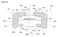
- the lens 210 incorporated in the holder member 40 is a combined lens, and includes a first lens element 212, a second lens element 213, and a diaphragm 215 sandwiched therebetween. .
- the first lens element 212 has a pair of optical surfaces 12d and 12e, and is formed of, for example, a curable resin having reflow heat resistance.
- the second lens element 213 has a pair of optical surfaces 13d and 13e, and is formed of a curable resin having reflow heat resistance, for example.
- the lens 210 and the holder member 40 are heated, so that the lens is formed when the holder member 40 is molded. Since the distortion formed in the elements 212 and 213 can be released, the optical surfaces 12d and 13e of the lens 210 can be returned to the original optical accuracy.
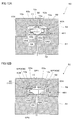
- the holding member 361 d provided in the back of the first molding portion 61 is a cylindrical protrusion, and the end surface 361 e that is a contact surface is the second optical of the lens 10. It has the same or substantially the same curvature as the surface 13e, and is configured to contact the second optical surface 13e (see FIG. 1A) of the lens 10 in a planar shape.
- the end surface 361e of the holding member 361d and the second optical surface 13e of the lens 10 are in close contact with each other in a planar shape, and the fluid resin MP can be prevented from leaking to the second optical surface 13e in the molding stage shown in FIG. 11B.
- the opening OP ⁇ b> 2 can be formed in the holder member 40.
- the fixing member 362d provided at the back of the second molding portion 62 is a cylindrical protrusion, and the end surface 362e that is a contact surface is the same as the first optical surface 12d of the lens 10. Alternatively, they have substantially the same curvature, and are configured to come into contact with the first optical surface 12d (see FIG. 1A) of the lens 10 in a planar shape. As a result, the end surface 362e of the fixing member 362d and the first optical surface 12d of the lens 10 are brought into close contact with each other in a planar shape, and the flowing resin MP can be prevented from leaking to the first optical surface 12d. As a result, the holder member 40 An opening OP1 can be formed in the opening.
- the holder member 40 can be obtained by heating the lens 10 and the holder member 40. Since the distortion formed in the lens 10 at the time of molding can be released, the first and second optical surfaces 12d and 13e of the lens 10 can be returned to the original optical accuracy.
- the first holder portion 461 of the first mold 51 is inserted into the concave portion of the first molding portion 461 by injection molding using a molding portion (not shown). 40A is formed.
- the lens 10 is not shown in detail, but has a slight gap with the inner surface (inner wall) of the side wall of the first holder portion 40A, and the bottom portion of the first holder portion 40A. While being supported by 42, the optical surface is positioned laterally so as to be aligned with the center of the holder opening. Note that when the lens 10 is set on the first holder portion 40A embedded in the first molding portion 61, an insert jig 70 shown in FIG. 6 is used.
- the transfer surface 62a for forming the upper part of the holder member 40 is formed in the second forming part 62 on the second mold 52 side. Further, the second molding portion 62 is formed with a cylindrical fixing member 62d that prevents the flowing resin MP from flowing into the space S2 adjacent to the first optical surface 12d of the lens 10.
- the first frame surface 10a of the lens 10 is covered with a resin by filling a fluid resin MP to be a material of the holder member 40 into a cavity CA2 that is a molding space.
- the 2nd holder part 40B is shape
- the first optical surface 12d is affected by the heat of the resin during the molding of the second holder portion 40B, and deforms at the location of the fixing member 62d provided in the second molding portion 62, so that the optical performance is improved. There is concern about the deterioration. However, since the lens 10 and the holder member 40 are heated after the first holder part 40A and the second holder part 40B are molded, the distortion formed in the lens 10 when the holder member 40 is molded can be released. The first optical surface 12d of the lens 10 can be returned to the original optical accuracy.
- the first holder portion 40A which is a resin body constituting a part of the holder, is arranged in the mold. Since the holder portion to be molded after the lens arrangement on the lens is less than that in the above-described embodiment, the distortion generated in the lens 10 can be reduced in the first place. Further, since the second optical surface 13e is in contact with the first holder portion 40A, which is a resin, it is not affected by heat during the molding of the second holder portion 40B. Accordingly, the second optical surface 13e is not deformed as generated in the first optical surface 12d when the second holder portion 40B is molded, and the optical performance is maintained. In addition, since such deformation does not occur, the optical performance is maintained even after the heat treatment.
- the shapes and structures of the lenses 10 and 210 are examples, and can be changed as appropriate.
- the lens 10 does not need to have a prismatic shape, and can have a cylindrical shape or the like.
- the lens 10 is held in the holder member 40.
- accessory parts such as an IR cut filter and a height adjustment plate.
- the imaging lens unit 100 including the heat treatment can be subjected to heat treatment, so that the distortion applied to the lens 10 when the holder member 40 is molded can be released and restored or restored to the original state.
- the vertical mold apparatus moves the second mold 52 in the vertical direction, but it may be a horizontal mold apparatus in which the movable mold moves in the left-right direction. In this case, in order to prevent the lens 10 or the like from falling, it is necessary to suck and hold the lens 10 or the like from at least one mold.
- thermoplastic resin is used as the resin material constituting the holder member.
- a curable resin such as a thermosetting resin can also be used.
- a plurality of molding portions may be provided on the mold, and holder molding may be performed simultaneously on a plurality of lenses.
- a member for alignment in each molding part it is not necessary to arrange a member for alignment in each molding part, and a common alignment member may be used for a plurality of molding parts.
Landscapes
- Physics & Mathematics (AREA)
- General Physics & Mathematics (AREA)
- Optics & Photonics (AREA)
- Engineering & Computer Science (AREA)
- Health & Medical Sciences (AREA)
- Manufacturing & Machinery (AREA)
- Ophthalmology & Optometry (AREA)
- Mechanical Engineering (AREA)
- Lens Barrels (AREA)
- Injection Moulding Of Plastics Or The Like (AREA)
- Moulds For Moulding Plastics Or The Like (AREA)
- Casting Or Compression Moulding Of Plastics Or The Like (AREA)
Abstract
Description
以下、図面を参照して、本発明の第1実施形態に係る撮像レンズユニットの構造やその製造方法について説明する。
図1A及び1Bに示すように、撮像レンズユニット100は、内部に収納される光機能部としてのレンズ10と、レンズ10を周囲から保持するケース状のホルダー部材40とを備える。
図2A及び2Bを参照して、レンズ10の第1光学面12dの劣化について説明する。ホルダー部材40は、上述のように樹脂の射出成形によって一体成形されるので、レンズ10の第1光学面12dと第1枠面10aとの間の狭い環状の境界部10mには、成形の際に、成形用の金型52から延びる固定部材62dの先端の端面62eが当接する。固定部材62dは、第1光学面12d側に流動樹脂が流れ込むことを防止しており不可欠的なものであるが、樹脂漏れを防止する観点から固定部材62dを所定以上の圧力で境界部10mに押し付ける必要があり、ホルダー成形時の樹脂の熱の影響も付加されて、図2Bに示すように境界部10mに陥没したような浅い窪み12rが形成される。この窪み12rは、元の表面レベルSOよりも数μm~数10μm程度低くなって周辺との間に段差を形成している。窪み12r自体は、第1光学面12dの外側にあり、レンズ10の性能に直接影響しない。しかしながら、発明者の検討により、窪み12rの発生が第1光学面12dの形状精度すなわち光学精度に影響していることが分かってきた。具体的には、レンズ10をホルダー部材40内に封入することによって第1光学面12dの形状精度が劣化し、窪み12rが深くなるほどこれに隣接する第1光学面12dの形状精度の劣化が著しくなることが判明した。第1光学面12dの形状精度の劣化は、撮像レンズユニット100の仕様により許容される場合もあるが、撮像レンズユニット100に要求される光学的仕様のレベルが益々高くなっていることを鑑みれば、第1光学面12dの形状変形を極力抑えることが望ましい。なお、上記のような窪み12rは、樹脂温度や金型温度を低下させることでもある程度浅くすることはできるが、射出成形時の樹脂の流動性が下がり、ホルダー部材40の外観不良等の別の問題が発生するため、樹脂温度や金型温度を低くすることで光学面の形状精度の劣化を防ぐことは難しい。
以下、図4のフローチャート等を参照して、撮像レンズユニット100の製造方法等について説明する。
以下、具体的な加熱処理について説明する。まず、加熱処理の対象である撮像レンズユニットとして、図1に示す構成を有する撮像レンズユニット100を、図4のステップS11~S18を実行することにより作製した。ここで、撮像レンズユニット100を構成するレンズ10の第1及び第2レンズ層12,13は、エポキシ系UV硬化性樹脂製であり、各レンズ層12,13を構成する樹脂の荷重撓み温度(ISO75 A法)は170℃であり、分解温度は約320℃である。第1及び第2レンズ層12,13に対するポストキュアは、200℃で1時間とした。また、ガラス基板11の厚みは0.3mm、ホルダー成形用金型(第1及び第2金型51,52)のレンズ当接部(保持部材61d、固定部材62d)に対応する部分の上面樹脂層(第1レンズ層12)の厚みは0.12mm、ホルダー成形用金型のレンズ当接部に対応する部分の下面樹脂層(第2レンズ層13)の厚みは0.05mm、レンズ10の外形は一辺が2.0mmの正方形形状とした。一方、撮像レンズユニット100を構成するホルダー部材40は、LCP(液晶ポリマー)樹脂製であり、ホルダー部材40を構成する樹脂の荷重撓み温度(ISO75 A法)は277℃、融点は320℃である。また、ホルダー成形用金型としては、レンズ当接部の形状が、上面側(固定部材62d)が外径1.26mm、内径1.00mmの環状、下面側(保持部材61d)が外径1.51mm、内径1.10mmの環状であり、ホルダー部材40の外側寸法の一辺が3.2mmとなるものを用いた。
以下、第2実施形態に係る撮像レンズユニットの構造やその製造方法について説明する。なお、第2実施形態の撮像レンズユニットの製造方法等は第1実施形態を部分的に変更したものであり、特に説明しない事項は第1実施形態と同様であるものとする。
以下、第3実施形態に係る撮像レンズユニットの構造やその製造方法について説明する。なお、第3実施形態の撮像レンズユニットの製造方法等は第1実施形態を部分的に変更したものであり、特に説明しない事項は第1実施形態と同様であるものとする。
以下、第4実施形態に係る撮像レンズユニットの構造やその製造方法について説明する。なお、第4実施形態の撮像レンズユニットの製造方法等は第1実施形態を部分的に変更したものであり、特に説明しない事項は第1実施形態と同様であるものとする。
Claims (15)
- ホルダー部材の少なくとも一部を成形するための成形空間を有する金型内に、少なくとも一部に樹脂を含むレンズを位置決めして配置するとともに、前記成形空間内に樹脂を充填して固化させることにより、前記レンズを内部に一体的に保持する前記ホルダー部材を形成する工程と、
前記ホルダー部材に保持された前記レンズを加熱処理することにより、前記ホルダー部材の形成によって発生した前記レンズの歪みを解放する工程と
を備える撮像レンズユニットの製造方法。 - 前記レンズは、基板とレンズ層とを含む複合型レンズであり、前記レンズ層は、樹脂製である、請求項1に記載の撮像レンズユニットの製造方法。
- 前記レンズは、複数のレンズ要素を一体化した組レンズであり、前記複数のレンズ要素のうち少なくとも1つのレンズ要素は、樹脂製である、請求項1に記載の撮像レンズユニットの製造方法。
- 前記レンズは、エネルギー硬化性の樹脂を用いて形成されている、請求項1から3までのいずれか一項に記載の撮像レンズユニットの製造方法。
- 前記レンズは、熱可塑性の樹脂を用いて形成されている、請求項1から3までのいずれか一項に記載の撮像レンズユニットの製造方法。
- 前記ホルダー部材は、LCP樹脂及びPPA樹脂の少なくとも一方で形成されている、請求項1から5までのいずれか一項に記載の撮像レンズユニットの製造方法。
- 前記金型は、前記レンズの表面に設けた少なくとも1つの光学面に樹脂が流入することを阻止する少なくとも1つの当接部材を有する、請求項1から6までのいずれか一項に記載の撮像レンズユニットの製造方法。
- 前記少なくとも1つの当接部材は、前記光学面を避けて前記光学面の外側に当接する、請求項7に記載の撮像レンズユニットの製造方法。
- 前記少なくとも1つの当接部材は、前記光学面と略同一の形状を有し前記光学面に当接する、請求項7に記載の撮像レンズユニットの製造方法。
- 前記加熱処理は、前記レンズの樹脂部分の荷重撓み温度より20℃低い下限温度以上で、かつ、前記レンズの樹脂部分の分解温度又は融点である上限温度よりも低い温度範囲で行われる、請求項1から9までのいずれか一項に記載の撮像レンズユニットの製造方法。
- 前記加熱処理は、前記レンズの使用環境温度の上限である260℃以下の温度範囲で行われる、請求項10に記載の撮像レンズユニットの製造方法。
- 前記ホルダー部材の荷重撓み温度は、前記レンズの樹脂部分の荷重撓み温度よりも高い、請求項1から11までのいずれか一項に記載の撮像レンズユニットの製造方法。
- 前記金型内に前記レンズを配置する前に、前記ホルダーの一部を構成する樹脂体が前記金型内に配置され、前記樹脂を前記金型内に充填して固化させることにより、該固化された樹脂と前記樹脂体とが接合し、前記ホルダー部材を形成する、請求項1から12までのいずれか一項に記載の撮像レンズユニットの製造方法。
- 第1光学面と第2光学面とを有するレンズと、
前記レンズを金型内に配置した状態で前記レンズの周辺に樹脂を供給して固化させることで形成され、前記レンズを内部に一体的に保持する前記ホルダー部材と、
を備え、
前記レンズは、前記ホルダー部材に保持された状態で加熱処理されている撮像レンズユニット。 - 前記レンズは、前記第1光学面と前記第2光学面との少なくとも一方に樹脂が流入することを阻止するために金型に設けた当接部材の当接痕を有する、請求項14に記載の撮像レンズユニット。
Priority Applications (3)
| Application Number | Priority Date | Filing Date | Title |
|---|---|---|---|
| JP2013507635A JP5962651B2 (ja) | 2011-03-28 | 2012-03-27 | 撮像レンズユニットの製造方法、及び、撮像レンズユニット |
| US14/007,879 US20140016216A1 (en) | 2011-03-28 | 2012-03-27 | Manufacturing method for image pickup lens unit and image pickup lens |
| CN201280016016.0A CN103443685B (zh) | 2011-03-28 | 2012-03-27 | 摄像镜头单元的制造方法以及摄像镜头单元 |
Applications Claiming Priority (2)
| Application Number | Priority Date | Filing Date | Title |
|---|---|---|---|
| JP2011-070985 | 2011-03-28 | ||
| JP2011070985 | 2011-03-28 |
Publications (1)
| Publication Number | Publication Date |
|---|---|
| WO2012133451A1 true WO2012133451A1 (ja) | 2012-10-04 |
Family
ID=46931165
Family Applications (1)
| Application Number | Title | Priority Date | Filing Date |
|---|---|---|---|
| PCT/JP2012/057997 Ceased WO2012133451A1 (ja) | 2011-03-28 | 2012-03-27 | 撮像レンズユニットの製造方法、及び、撮像レンズユニット |
Country Status (5)
| Country | Link |
|---|---|
| US (1) | US20140016216A1 (ja) |
| JP (1) | JP5962651B2 (ja) |
| CN (1) | CN103443685B (ja) |
| TW (1) | TWI537626B (ja) |
| WO (1) | WO2012133451A1 (ja) |
Cited By (2)
| Publication number | Priority date | Publication date | Assignee | Title |
|---|---|---|---|---|
| WO2013047653A1 (ja) * | 2011-09-30 | 2013-04-04 | コニカミノルタアドバンストレイヤー株式会社 | 撮像レンズユニット及び撮像レンズユニットの製造方法 |
| JP2019028445A (ja) * | 2017-08-02 | 2019-02-21 | 信泰光學(深セン)有限公司 | カメラ装置 |
Families Citing this family (10)
| Publication number | Priority date | Publication date | Assignee | Title |
|---|---|---|---|---|
| TWI551428B (zh) * | 2010-09-30 | 2016-10-01 | 柯尼卡美能達精密光學股份有限公司 | 攝像透鏡單元之製造方法 |
| JP2015178197A (ja) * | 2014-03-19 | 2015-10-08 | コニカミノルタ株式会社 | 保持装置、光学ユニットの製造方法及び光学ユニット |
| US9718405B1 (en) | 2015-03-23 | 2017-08-01 | Rosco, Inc. | Collision avoidance and/or pedestrian detection system |
| US9952415B2 (en) * | 2015-04-22 | 2018-04-24 | Omnivision Technologies, Inc. | Trenched-substrate based lens manufacturing methods, and associated systems |
| JP6493549B2 (ja) * | 2015-10-06 | 2019-04-03 | 日産自動車株式会社 | 燃料電池スタック |
| JP2019012111A (ja) * | 2017-06-29 | 2019-01-24 | 日本電産サンキョー株式会社 | レンズユニット |
| US11209578B2 (en) | 2017-08-02 | 2021-12-28 | Sintai Optical (Shenzhen) Co., Ltd. | Camera device |
| CN109443278B (zh) * | 2018-11-30 | 2024-11-08 | 松林光电科技(湖北)有限公司 | 一种透镜外径误差非旋转式检测装置 |
| US12115916B2 (en) | 2021-02-01 | 2024-10-15 | Rosco, Inc. | Downlighting signal and illumination mirror head for vehicle |
| JP7602424B2 (ja) * | 2021-04-12 | 2024-12-18 | アルプスアルパイン株式会社 | 鏡筒付レンズ |
Citations (4)
| Publication number | Priority date | Publication date | Assignee | Title |
|---|---|---|---|---|
| JP2005129640A (ja) * | 2003-10-22 | 2005-05-19 | Sanken Electric Co Ltd | 半導体発光装置の製法 |
| JP2006018253A (ja) * | 2004-06-04 | 2006-01-19 | Sekinosu Kk | 光学部材及びその製造方法 |
| JP2010204632A (ja) * | 2009-02-06 | 2010-09-16 | Fujifilm Corp | ウェハレベルレンズアレイの製造方法、ウェハレンズアレイ、レンズモジュール及び撮像ユニット |
| JP2010243659A (ja) * | 2009-04-02 | 2010-10-28 | Sumitomo Electric Fine Polymer Inc | 光学レンズ−ホルダー複合体の製造方法、及び光学レンズ−ホルダー複合体 |
Family Cites Families (7)
| Publication number | Priority date | Publication date | Assignee | Title |
|---|---|---|---|---|
| JPS6416623A (en) * | 1987-07-13 | 1989-01-20 | Hitachi Ltd | Mold for plastic lens |
| JP2005043690A (ja) * | 2003-07-23 | 2005-02-17 | Fujinon Corp | プラスチックレンズの保持方法およびプラスチックレンズの保持構造 |
| JP2007141416A (ja) * | 2005-11-22 | 2007-06-07 | Sumitomo Electric Fine Polymer Inc | レンズホルダー、光ピックアップ、光記録再生装置およびレンズホルダーの製造方法 |
| JP2008155577A (ja) * | 2006-12-26 | 2008-07-10 | Fujifilm Corp | レンズ成形用金型およびレンズの製造方法 |
| EP2168757B1 (en) * | 2007-07-25 | 2015-04-29 | Hoya Corporation | Method of manufacturing a plastic lens |
| JP5009209B2 (ja) * | 2008-03-21 | 2012-08-22 | シャープ株式会社 | ウエハ状光学装置およびその製造方法、電子素子ウエハモジュール、センサウエハモジュール、電子素子モジュール、センサモジュール、電子情報機器 |
| TW201100900A (en) * | 2009-06-30 | 2011-01-01 | E Pin Optical Industry Co Ltd | Lens holder for stacked lens module and the method for manufacturing thereof |
-
2012
- 2012-03-22 TW TW101109863A patent/TWI537626B/zh not_active IP Right Cessation
- 2012-03-27 WO PCT/JP2012/057997 patent/WO2012133451A1/ja not_active Ceased
- 2012-03-27 US US14/007,879 patent/US20140016216A1/en not_active Abandoned
- 2012-03-27 CN CN201280016016.0A patent/CN103443685B/zh not_active Expired - Fee Related
- 2012-03-27 JP JP2013507635A patent/JP5962651B2/ja not_active Expired - Fee Related
Patent Citations (4)
| Publication number | Priority date | Publication date | Assignee | Title |
|---|---|---|---|---|
| JP2005129640A (ja) * | 2003-10-22 | 2005-05-19 | Sanken Electric Co Ltd | 半導体発光装置の製法 |
| JP2006018253A (ja) * | 2004-06-04 | 2006-01-19 | Sekinosu Kk | 光学部材及びその製造方法 |
| JP2010204632A (ja) * | 2009-02-06 | 2010-09-16 | Fujifilm Corp | ウェハレベルレンズアレイの製造方法、ウェハレンズアレイ、レンズモジュール及び撮像ユニット |
| JP2010243659A (ja) * | 2009-04-02 | 2010-10-28 | Sumitomo Electric Fine Polymer Inc | 光学レンズ−ホルダー複合体の製造方法、及び光学レンズ−ホルダー複合体 |
Cited By (3)
| Publication number | Priority date | Publication date | Assignee | Title |
|---|---|---|---|---|
| WO2013047653A1 (ja) * | 2011-09-30 | 2013-04-04 | コニカミノルタアドバンストレイヤー株式会社 | 撮像レンズユニット及び撮像レンズユニットの製造方法 |
| US9151925B2 (en) | 2011-09-30 | 2015-10-06 | Konica Minolta, Inc. | Image pickup lens unit and method for manufacturing image pickup lens unit |
| JP2019028445A (ja) * | 2017-08-02 | 2019-02-21 | 信泰光學(深セン)有限公司 | カメラ装置 |
Also Published As
| Publication number | Publication date |
|---|---|
| TW201303406A (zh) | 2013-01-16 |
| CN103443685A (zh) | 2013-12-11 |
| JPWO2012133451A1 (ja) | 2014-07-28 |
| JP5962651B2 (ja) | 2016-08-03 |
| TWI537626B (zh) | 2016-06-11 |
| US20140016216A1 (en) | 2014-01-16 |
| CN103443685B (zh) | 2015-09-23 |
Similar Documents
| Publication | Publication Date | Title |
|---|---|---|
| JP5962651B2 (ja) | 撮像レンズユニットの製造方法、及び、撮像レンズユニット | |
| US8982486B2 (en) | Image pickup lens unit manufacturing method and image pickup lens unit | |
| JP3154934U (ja) | 組合わせレンズモジュールのレンズホルダー | |
| JP5910628B2 (ja) | 撮像レンズユニットの製造方法 | |
| TWI551428B (zh) | 攝像透鏡單元之製造方法 | |
| JP6627933B2 (ja) | 撮像レンズユニットの製造方法、及び、撮像レンズユニット | |
| JPWO2013154121A1 (ja) | レンズユニット | |
| JP2009300626A (ja) | 光学ガラスレンズセット及びその製法 | |
| US9151925B2 (en) | Image pickup lens unit and method for manufacturing image pickup lens unit | |
| JP5880567B2 (ja) | 撮像レンズユニット | |
| JP5835338B2 (ja) | 撮像レンズユニットの製造方法 | |
| JP2007022905A (ja) | 光学素子デバイスの製造方法、光学素子デバイス、および成形装置 | |
| JP2013014455A (ja) | ガラス光学素子の製造方法 | |
| JP3154933U (ja) | スタックレンズモジュールの位置決めレンズホルダー | |
| JP6409870B2 (ja) | 光学素子の成形方法、成形型、及び光学素子 | |
| KR20110001228U (ko) | 적층 렌즈 모듈의 정렬을 위한 렌즈 홀더 |
Legal Events
| Date | Code | Title | Description |
|---|---|---|---|
| 121 | Ep: the epo has been informed by wipo that ep was designated in this application |
Ref document number: 12764815 Country of ref document: EP Kind code of ref document: A1 |
|
| ENP | Entry into the national phase |
Ref document number: 2013507635 Country of ref document: JP Kind code of ref document: A |
|
| WWE | Wipo information: entry into national phase |
Ref document number: 14007879 Country of ref document: US |
|
| NENP | Non-entry into the national phase |
Ref country code: DE |
|
| 122 | Ep: pct application non-entry in european phase |
Ref document number: 12764815 Country of ref document: EP Kind code of ref document: A1 |