WO2012133053A1 - 梱包箱 - Google Patents
梱包箱 Download PDFInfo
- Publication number
- WO2012133053A1 WO2012133053A1 PCT/JP2012/057202 JP2012057202W WO2012133053A1 WO 2012133053 A1 WO2012133053 A1 WO 2012133053A1 JP 2012057202 W JP2012057202 W JP 2012057202W WO 2012133053 A1 WO2012133053 A1 WO 2012133053A1
- Authority
- WO
- WIPO (PCT)
- Prior art keywords
- cut
- raised
- surface portion
- flap
- packaging box
- Prior art date
- Legal status (The legal status is an assumption and is not a legal conclusion. Google has not performed a legal analysis and makes no representation as to the accuracy of the status listed.)
- Ceased
Links
Images


Classifications
-
- B—PERFORMING OPERATIONS; TRANSPORTING
- B65—CONVEYING; PACKING; STORING; HANDLING THIN OR FILAMENTARY MATERIAL
- B65D—CONTAINERS FOR STORAGE OR TRANSPORT OF ARTICLES OR MATERIALS, e.g. BAGS, BARRELS, BOTTLES, BOXES, CANS, CARTONS, CRATES, DRUMS, JARS, TANKS, HOPPERS, FORWARDING CONTAINERS; ACCESSORIES, CLOSURES, OR FITTINGS THEREFOR; PACKAGING ELEMENTS; PACKAGES
- B65D5/00—Rigid or semi-rigid containers of polygonal cross-section, e.g. boxes, cartons or trays, formed by folding or erecting one or more blanks made of paper
- B65D5/42—Details of containers or of foldable or erectable container blanks
- B65D5/44—Integral, inserted or attached portions forming internal or external fittings
- B65D5/50—Internal supporting or protecting elements for contents
- B65D5/5021—Integral elements for containers formed by folding-up portions connected to a central panel from all sides
-
- B—PERFORMING OPERATIONS; TRANSPORTING
- B65—CONVEYING; PACKING; STORING; HANDLING THIN OR FILAMENTARY MATERIAL
- B65D—CONTAINERS FOR STORAGE OR TRANSPORT OF ARTICLES OR MATERIALS, e.g. BAGS, BARRELS, BOTTLES, BOXES, CANS, CARTONS, CRATES, DRUMS, JARS, TANKS, HOPPERS, FORWARDING CONTAINERS; ACCESSORIES, CLOSURES, OR FITTINGS THEREFOR; PACKAGING ELEMENTS; PACKAGES
- B65D2585/00—Containers, packaging elements or packages specially adapted for particular articles or materials
- B65D2585/68—Containers, packaging elements or packages specially adapted for particular articles or materials for machines, engines, or vehicles in assembled or dismantled form
- B65D2585/6802—Containers, packaging elements or packages specially adapted for particular articles or materials for machines, engines, or vehicles in assembled or dismantled form specific machines, engines or vehicles
- B65D2585/6815—Containers, packaging elements or packages specially adapted for particular articles or materials for machines, engines, or vehicles in assembled or dismantled form specific machines, engines or vehicles kitchen devices, including unspecified devices, e.g. Haushaltgeräte
- B65D2585/682—Containers, packaging elements or packages specially adapted for particular articles or materials for machines, engines, or vehicles in assembled or dismantled form specific machines, engines or vehicles kitchen devices, including unspecified devices, e.g. Haushaltgeräte cookers or dryers
-
- B—PERFORMING OPERATIONS; TRANSPORTING
- B65—CONVEYING; PACKING; STORING; HANDLING THIN OR FILAMENTARY MATERIAL
- B65D—CONTAINERS FOR STORAGE OR TRANSPORT OF ARTICLES OR MATERIALS, e.g. BAGS, BARRELS, BOTTLES, BOXES, CANS, CARTONS, CRATES, DRUMS, JARS, TANKS, HOPPERS, FORWARDING CONTAINERS; ACCESSORIES, CLOSURES, OR FITTINGS THEREFOR; PACKAGING ELEMENTS; PACKAGES
- B65D81/00—Containers, packaging elements, or packages, for contents presenting particular transport or storage problems, or adapted to be used for non-packaging purposes after removal of contents
- B65D81/02—Containers, packaging elements, or packages, for contents presenting particular transport or storage problems, or adapted to be used for non-packaging purposes after removal of contents specially adapted to protect contents from mechanical damage
- B65D81/05—Containers, packaging elements, or packages, for contents presenting particular transport or storage problems, or adapted to be used for non-packaging purposes after removal of contents specially adapted to protect contents from mechanical damage maintaining contents at spaced relation from package walls, or from other contents
- B65D81/053—Corner, edge or end protectors
- B65D81/057—Protectors contacting four surfaces of the packaged article, e.g. four-sided corner protectors
Definitions
- the present invention relates to a packing box for packing products.
- a packaging box there is one in which a cushioning material is fitted to the upper and lower parts of a product and accommodated inside (Japanese Patent Laid-Open No. 8-72938, FIG. 8 (Patent Document 1)).
- the cushioning material fitted to the upper and lower parts of the product is located between the product and the packaging box, and protects the product by absorbing external impacts during the transportation of the product. This prevents the product from being damaged.
- the product can be prevented from being damaged.
- the cushioning material is present at the upper and lower parts of the product, a large amount of cushioning material is required in addition to the packaging box, and the packaging cost is high.
- the cushioning material increases the size of the packaging box, which makes it difficult for the user to carry it during transportation.
- there is a problem that the number of containers that can be put in is reduced, the number that can be transported at one time is limited, and the cost of transportation is high.
- an object of the present invention is to provide a packaging box that can suppress the damage of the product during the transportation of the product, and is small and compact, and can reduce the cost of packaging and transportation.
- the packaging box of the present invention is The top and A bottom surface portion facing the top surface portion; Comprising four side portions located between the top surface portion and the bottom surface portion,
- the top part is With an inner flap, An outer flap superimposed on the outer side of the inner flap,
- the inner flap has a plurality of cut-and-raised portions that can be cut and raised so as to be positioned between the side surface portion and the article to be packed.
- the inner side flap of the top surface portion has a plurality of raised portions that can be cut and raised so as to be positioned between the side surface portion and the article to be packed, in a state where the raised portion is cut and raised,
- the cut-and-raised part can be positioned between the side part and the article to be packed. For this reason, even if an external impact or the like is applied to the packaging box, the cut and raised portion can be reduced by contacting the packaged item, and the excessive movement of the packaged product can be restricted. it can.
- the cut and raised part can function as a buffer part, the packaged object can be protected, and damage to the packaged object during transportation can be suppressed.
- the plurality of cut and raised portions are provided on the inner side flaps of the top surface portion and extend downward from the top surface portion of the packing box in the packed state.
- the movement of objects in the horizontal direction can be restricted. For this reason, it is not necessary to separately provide a cushioning material on the upper part of the packaged item, and the cushioning material on the upper part can be omitted, or the cushioning material can be made smaller, and the height dimension of the packaging box can be reduced. . Therefore, since the packaging box can be made small and compact, it is easy to carry, and more packaging boxes can be put in the container, and many packaging boxes can be transported at a time, thereby reducing transportation costs. .
- the upper cushioning material can be omitted, the material cost of the cushioning material can be reduced, and the packaging cost can be reduced.
- the outer side flap of the top surface part is overlapped with the outer side of the inner side flap of the top surface part, so that the inner flap is cut and raised to form a hole in the inner flap.
- the cut and raised portion of the inner flap is A first cut-and-raised portion that is cut and raised so as to be positioned between the side portion facing in one direction and the article to be packed; A second cut-and-raised portion that is cut and raised so as to be positioned between the side surface portion facing in the other direction intersecting with the one direction and the article to be packed;
- the first cut-and-raised part is positioned between the side part facing in one direction and the article to be packed in a state in which the first cut-and-raised part is cut and raised. Further, in a state where the second cut-and-raised portion is cut and raised, the second cut-and-raised portion comes to be positioned between the side portion facing in the other direction intersecting the one direction and the article to be packed. Therefore, since the first and second cut-and-raised parts can be brought into contact with the package object and excessive movement of the package object can be restricted in the two directions, the one direction and the other direction. The package can be protected more reliably, and damage to the packaged item during transportation can be more reliably suppressed.
- the first cut and raised portion is provided at a corner of the inner flap.
- the second cut and raised portion can be easily formed only by providing one cut on the inner flap. Can be formed.
- the packaging box of the present invention is The top and A bottom surface portion facing the top surface portion; Comprising four side portions located between the top surface portion and the bottom surface portion,
- the bottom part is With an inner flap, An outer flap superimposed on the outer side of the inner flap,
- the inner flap has a plurality of cut-and-raised portions that can be cut and raised so as to be positioned between the side surface portion and the article to be packed.
- the inner flap of the bottom surface portion has a plurality of cut and raised portions that can be cut and raised so as to be positioned between the side surface portion and the article to be packed.
- the cut-and-raised portion can be positioned between the side surface portion and the article to be packed.
- the cut-and-raised part can be reduced by contacting the packed object, and excessive movement of the packed object is restricted. can do.
- the said raising part can be functioned as a buffer part, the said to-be-packaged object can be protected and the damage of the to-be-packaged object at the time of conveyance can be suppressed.
- the packaging box can be made small and compact, it is easy to carry, and more packaging boxes can be put in the container, and many packaging boxes can be transported at a time, thereby reducing transportation costs. .
- the material cost of the cushioning material can be reduced, and the packaging cost can be reduced.
- the outer side flap of the bottom surface part is overlapped with the outer side of the inner side flap of the bottom surface part. Even if formed, there is no hole that communicates the outside and inside of the packaging box. Therefore, foreign substances such as insects can be reliably prevented from entering from the outside to the inside of the packaging box, and the appearance of the packaging box can be prevented from being damaged.
- the cut-and-raised portion of at least one inner flap of the top surface portion and the bottom surface portion is positioned between the side surface portion of the packing box and the packing object. It is possible to provide a packaging box that can suppress damage to the article to be packed at the time, and that is small and compact, and that can reduce packaging and transportation costs.
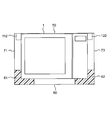
- FIG. 1 It is a perspective view for demonstrating the packing using the packing box of 1st Embodiment of this invention. It is a perspective view which shows the state which accommodated the microwave oven in the said packaging box, and the inner side flap and the outer side flap opened. It is a figure which shows the state before the 1st inner side flap part is in the open state, the 2nd inner side flap part is in the closed state, and the cut-and-raised part is cut and raised. It is a top view which shows the position of the said raising part in the said packing state. It is sectional drawing when a packing box of a packing state is cut
- FIG. 1 is a perspective view for explaining packing of a packaging box according to a first embodiment of the present invention, and is a perspective view in a state where an upper cover of the packaging box is opened.
- This packing box is formed by cutting out from a single sheet-like cardboard material having a substantially constant thickness.
- the packing box is in a packed state, a top surface portion, a bottom surface portion 60 facing the top surface portion in the height direction, and first to fourth side surface portions 71 to 41 located between the top surface portion and the bottom surface portion 60. 74.
- Each surface shape of the top surface portion and the bottom surface portion 60 has a rectangular shape having a long side and a short side.
- the top surface portion has an inner flap 10 and an outer flap 20 that is superimposed on the outer side of the inner flap 10. In the state of the packaging box shown in FIG. 1, the top lid of the packaging box is open and the top surface portion does not exist, and each of the inner side flap 10 and the outer side flap 20 is bent to the outside of the packaging box. It has been.
- the first to fourth side portions 71 to 74 are sequentially positioned counterclockwise when viewed downward in the vertical direction.
- the first side surface portion 71 is located between one short side of the top surface portion and one short side of the bottom surface portion 60 facing the short side
- the third side surface portion 73 is the top surface portion. It is located between the other short side and the other short side of the bottom surface portion 60.
- the second side surface portion 72 is located between one long side of the top surface portion and one long side of the bottom surface portion 60 facing the long side
- the fourth side surface portion 74 is It is located between the other long side of the surface portion and the other long side of the bottom surface portion 60.
- the cooking device 1 as an example of an object to be packed is stored and packed as follows. First, the 1st and 2nd bottom buffer materials 61 and 62 which have a recessed part in an upper surface are prepared. Next, the first bottom cushioning material 61 is disposed on the bottom surface portion 60 so as to be along one short side of the bottom surface portion 60 in a state where the concave portion is present above. In addition, the second bottom cushioning material 62 is disposed along the other short side of the bottom surface portion 60 with a distance from the first bottom cushioning material 61 and the concave portion existing above.
- the first and second bottom cushioning members 61 and 62 are made of an integrally molded product of synthetic resin such as foamed polystyrene having elasticity. Each of the concave portions of the first and second bottom cushioning members 61 and 62 has a shape corresponding to the shape of the bottom surface portion of the heating cooker 1.
- the bottom portion of the heating cooker 1 is fitted into the recesses of the first and second bottom cushioning materials 61 and 62. In this way, the cooking device 1 is stored in the packaging box.
- the inner flap 10 is folded inward and closed, a measure for suppressing the breakage of the heating cooker 1 described with reference to FIG. 2 and subsequent figures is performed, and finally the outer flap 20 is folded inward, The outer flap 20 is overlaid on the outside. In this way, the cooking device 1 is packed. In this packing state, the packing box is formed in a rectangular parallelepiped.
- FIG. 2 is a perspective view showing a state where the cooking device 1 is housed in the packing box and the inner flap 10 and the outer flap 20 are opened.
- the bottom cushioning material 61 includes a bottom surface portion 60, a first side surface in a state where the bottom surface portion of the heating cooker 1 is fitted in the recesses of the first and second bottom cushioning members 61 and 62.
- the portion 71, the second side surface portion 72, and the fourth side surface portion 74 are in contact with each other.
- the bottom buffer material 62 includes the bottom surface portion 60, the second side surface portion 72, the second The third side surface portion 73 and the fourth side surface portion 74 are in contact with each other.
- the heating cooker 1 is protected by the first and second bottom cushioning materials 61 and 62, and from the bottom surface portion 60 and the first through the first and second bottom cushioning materials 61 and 62. Positioning is performed with respect to the fourth side portions 71 to 74.
- the outer flap 20 has a first outer flap portion 21 and a second outer flap portion 22 that faces the first outer flap portion 21.
- the first outer flap portion 21 is formed in a rectangular shape, and one long side of the first outer flap portion 21 coincides with the upper edge of the second side surface portion 72.
- the second outer flap portion 22 is formed in substantially the same shape and size as the first outer flap portion 21, and has one long side of the second outer flap portion 22 and the fourth side surface. It coincides with the upper edge of the portion 74.
- the inner flap 10 includes a first inner flap portion 11 and a second inner flap portion 12 that faces the first inner flap portion 11.
- the first inner flap portion 11 is formed in a rectangular shape, and one long side of the first inner flap portion 11 coincides with the upper edge of the first side surface portion 71.
- the second inner flap portion 12 is formed in substantially the same shape and size as the first inner flap portion 21, and has one long side of the second inner flap portion 12 and the third side surface.
- the upper edge of the portion 73 coincides with the upper edge.
- Each of the first and second inner flap portions 11 and 12 has four substantially rectangular cut-and-raised portions having substantially the same size.
- the four cut-and-raised portions of the first inner flap portion 11 and the four cut-and-raised portions of the second inner flap portion 12 are perpendicular to the long side direction of the top surface portion. They are arranged substantially symmetrically with respect to a plane that bisects in any direction.
- FIG. 3 is a diagram showing a state in which the first inner flap portion 11 is open, while the second inner flap portion 12 is in a closed state, and before the cut-and-raised portion is cut and raised. .
- the first to fourth cut-and-raised portions 121 to 124 which are the four cut-and-raised portions of the second inner flap portion 12, are positioned counterclockwise.
- the first to fourth cut-and-raised portions 121 to 124 are formed by cutting the second inner flap portion 12.
- the first cut-and-raised part 121 is located at the approximate center in the short side direction of the second inner flap part 12 and is oriented in the long side direction of the second inner flap part 12 as one direction. It is located between the side part 72 and the heating cooker 1.
- a dotted line 185 indicates a side surface of the cooking device 1 that is not actually visible.
- One edge of the first cut-and-raised part 121 extending in the extending direction thereof overlaps the side surface of the heating cooker 1 facing the second side part 72 and extending in the longitudinal direction.
- the first cut-and-raised portion 121 can be cut and raised by a connecting portion 121a extending in a direction perpendicular to the extending direction of the first cut-and-raised portion 121, which is indicated by a dotted line in the drawing.
- the connecting portion 121a defines a part of the first cut and raised portion 121.
- the fourth cut-and-raised portion 124 is provided in the second inner flap portion 12 so as to face the first cut-and-raised portion 121.
- the fourth cut-and-raised portion 124 is located at the approximate center in the short side direction of the second inner flap portion 12, and in the long side direction of the second inner flap portion 12, the cooking device 1 and the fourth It is located between the side part 74.
- One edge of the fourth cut-and-raised portion 124 extending in the extending direction overlaps the side surface of the heating cooker 1 facing the fourth side surface portion 74.
- the fourth cut-and-raised portion 124 can be cut and raised by a connection portion 124a extending in a direction perpendicular to the extending direction of the fourth cut-and-raised portion 124, which is indicated by a dotted line in the drawing.
- the connection portion 124 a defines a part of the fourth cut and raised portion 124.
- the second and third cut-and-raised portions 122 and 123 are positioned at a distance from each other along the long side direction of the second inner flap portion 12 and as other directions orthogonal to the long side direction. It is located between the third side surface portion 73 facing the short side direction and the heating cooker 1.
- the second cut-and-raised portion 122 and the third cut-and-raised portion 123 are disposed substantially symmetrically with respect to a plane that bisects the second inner flap portion 12 in a direction perpendicular to the long side direction.
- the second cut-and-raised portion 122 can be cut and raised by a connecting portion 122a extending in a direction perpendicular to the extending direction of the second cut-and-raised portion 122, which is indicated by a dotted line in the drawing.
- the connection portion 122 a defines a part of the second cut and raised portion 122.
- the extending direction of the second cut-and-raised portion 122 is inclined with respect to the bottom surface portion 60, and the third side surface portion 73 is provided. And a side surface of the heating cooker 1 extending in the width direction thereof.
- the third cut-and-raised portion 123 extending in the extending direction thereof overlaps with a side surface of the heating cooker 1 facing the third side surface portion 73 and extending in the width direction thereof.
- the third cut-and-raised portion 123 can be cut and raised by a connecting portion 123a extending in a direction orthogonal to the extending direction of the third cut-and-raised portion 123, which is indicated by a dotted line in the drawing.
- the connection portion 123 a defines a part of the third cut and raised portion 123.
- the extending direction of the third cut-and-raised portion 123 is inclined with respect to the bottom surface portion 60, and the third side surface portion 73 is provided. And a side surface of the heating cooker 1 extending in the width direction thereof.
- the corners at both ends of the edge on the front end side in the extending direction of the first to fourth cut and raised portions 121 to 124 are chamfered.
- FIG. 4 is a top view showing the positions of the cut and raised portions 111 to 114 and 171 to 174 in the packed state.
- illustration of the 1st, 2nd outer side flap parts 21 and 22 is abbreviate
- the first to fourth cut-and-raised portions 111 to 114 of the first inner flap portion 11 and the first to fourth cut-and-raised portions 121 to 124 of the second inner flap portion 12 Are cut and raised and extend in a direction perpendicular to the top surface portion 50.
- the first cut-and-raised part 111 of the first inner flap part 11 and the first cut-and-raised part 121 of the second inner flap part 12 are the extension part in the longitudinal direction of the heating cooker 1 and the second It is located between the side part 72 of this.
- one edge in the direction orthogonal to the extending direction of the first cut and raised portions 111 and 121 is in contact with the side surface of the heating cooker 1 facing the second side surface portion 72.
- the 4th raising part 114 of the 1st inner side flap part 11 and the 4th raising part 124 of the 2nd inner side flap part 12 are the heating cooker 1, the 4th side surface part 74, and Located between.
- one edge of the fourth cut-and-raised portions 114 and 124 extending in the extending direction thereof contacts the side surface of the heating cooker 1 facing the fourth side surface portion 74 and extending in the longitudinal direction thereof. ing.
- the second and third cut-and-raised portions 112 and 113 of the first inner flap portion 11 are positioned between the side surface extending in the width direction of the heating cooker 1 and the first side surface portion 71. ing. Each of the second and third cut-and-raised portions 112 and 113 extends in the width direction of the heating cooker 1 facing the first side surface 71 at one edge extending in each extending direction. It touches the existing side.
- the second and third cut-and-raised portions 122 and 123 of the second inner flap portion 12 are positioned between the side surface extending in the width direction of the heating cooker 1 and the third side surface portion 73. is doing.
- Each of the second and third cut-and-raised portions 122 and 123 extends in the width direction of the heating cooker 1 facing the third side surface portion 73 at one edge extending in each extending direction. It touches the existing side.
- the holes 161 to 164 are formed by cutting and raising the first to fourth cut and raised portions 111 to 114 of the first inner flap portion 11.
- the holes 171 to 174 are formed by cutting and raising the first to fourth cut and raised portions 121 to 124 of the second inner flap portion 12.
- the leading edge of the first inner flap portion 11 and the leading edge of the second inner flap portion 12 are positioned at a certain distance in the packed state.
- the edge on the front end side of the first outer flap portion 21 and the edge on the front end side of the second outer flap portion 22 are in contact with each other in a packed state. Is located on the center line L in the short side direction.
- the first and second outer flap portions 21 and 22 cover the first and second inner flap portions 11 and 12, and an opening between the first inner flap portion 11 and the second inner flap portion 12. It is designed to cover everything.
- FIG. 5 is a cross-sectional view of the packed packaging box taken along the plane indicated by the line AA in FIG. 4 including the height direction and the longitudinal direction of the packaging box.
- the second cut and raised portion 112 is positioned between the heating cooker 1 and the first side surface portion 71.
- One edge of the second cut-and-raised portion 112 extending in the extending direction contacts the side surface of the heating cooker 1, while the other edge of the second cut-and-raised portion 112 in the extending direction is
- the first side surface portion 71 is located at a certain distance.
- the second cut and raised portion 122 is located between the heating cooker 1 and the third side surface portion 73.
- the third side surface portion 73 is located at a certain distance.
- the top surface portion 50 of the packaging box is opposed to the top surface of the heating cooker 1 in the vertical direction with almost no distance. Further, no member is arranged between the top surface portion 50 and the upper surface of the heating cooker 1.
- the first bottom cushioning material 61 abuts against the side surface of the heating cooker 1 facing the first side surface portion 71 and the bottom surface of the heating cooker 1, while the first The second bottom cushioning material 62 is in contact with the side surface of the heating cooker 1 facing the third side surface portion 73 and the bottom surface of the heating cooker 1.
- the inner flap 10 can be cut and raised so as to be positioned between the first to fourth side portions 71 to 74 and the heating cooker 1. Since the raised portions 111 to 114 and 121 to 124 are included, the first to fourth cut and raised portions 111 to 114, with the first to fourth cut and raised portions 111 to 114 and 121 to 124 being cut and raised, 121 to 124 can be positioned between the first to fourth side surface portions 71 to 74 and the heating cooker 1.
- the first to fourth cut-and-raised portions 111 to 114 and 121 to 124 come into contact with the heating cooker 1 so that the heating cooker 1 The impact can be mitigated, and excessive movement of the heating cooker 1 can be restricted.
- the first to fourth cut-and-raised portions 111 to 114 and 121 to 124 can function as buffer portions, the cooking device 1 can be protected and the cooking device 1 can be damaged during transportation. Can be suppressed.
- first to fourth cut-and-raised portions 111 to 114 and 121 to 124 are provided on the inner flap 10 so as to extend downward from the top surface portion 50 of the packaging box in a packed state. Therefore, the movement of the cooking device 1 in the horizontal direction can be restricted at the top of the cooking device 1. For this reason, it is not necessary to separately provide a cushioning material on the upper part of the heating cooker 1, the cushioning material on this upper part can be omitted, or the cushioning material can be made smaller, and the height dimension of the packaging box can be reduced. . Therefore, since the packaging box can be made small and compact, it is easy to carry, and more packaging boxes can be put in the container, and many packaging boxes can be transported at a time, thereby reducing transportation costs. .
- the upper cushioning material can be omitted, the material cost of the cushioning material can be reduced, and the packaging cost can be reduced.
- the outer flap 20 is overlapped on the outer side of the inner flap 10, so that the first to fourth cut-and-raised portions 111 to 114 and 121 to 124 of the inner flap 10 are cut. Even if the holes 161 to 164 and 171 to 174 are formed in the inner flap 10 by being raised, there is no hole that communicates the outside and the inside of the packaging box. Therefore, foreign substances such as insects can be reliably prevented from entering from the outside to the inside of the packaging box, and the appearance of the packaging box can be prevented from being damaged.
- the first cut-and-raised portion 121 and the second side surface portion 72 facing the long side of the second inner flap portion 12 and the heating cooker 1 It will be located between.
- the first and second cut-and-raised parts 121 and 122 are brought into contact with the heating cooker 1 to cause excessive movement of the heating cooker 1 in the long side direction and in the direction orthogonal to the long side direction. Since it can regulate in one direction, heating cooker 1 can be protected more certainly, and breakage of heating cooker 1 at the time of transportation can be controlled more certainly.
- the first to fourth cut-and-raised portions 111 to 114 and 121 to 124 are located between the first to fourth side surface portions 71 to 74 and the heating cooker 1. Therefore, since the first to fourth cut-and-raised portions 111 to 114 and 121 to 124 are brought into contact with the heating cooker 1, excessive movement of the heating cooker 1 can be restricted in four directions. The cooker 1 can be protected more reliably, and damage to the heating cooker 1 during transportation can be reliably suppressed.
- the 1st cut-and-raised part 111 of the 1st inner side flap part 11 is located between the heating cooker 1 and the 2nd side part 72
- the 1st inner side flap part 11 The fourth cut-and-raised portion 114 is positioned between the heating cooker 1 and the fourth side surface portion 74.
- the first cut-and-raised portion 121 of the second inner flap portion 12 is located between the heating cooker 1 and the second side surface portion 72, while the fourth inner flap portion 12 has a fourth shape.
- the cut-and-raised part 124 is positioned between the heating cooker 1 and the fourth side part 74.
- the first to fourth cut-and-raised portions 111 to 114 and 121 to 124 come into contact with the side surfaces of the heating cooker 1, respectively.
- the cut-and-raised portions 111 to 114 and 121 to 124 can prevent the cooking device 1 from moving, and the cooking device 1 can be reliably protected. Further, since the heating cooker 1 can be held by the first to fourth cut and raised portions 111 to 114 and 121 to 124, the heating cooker 1 can be positioned.
- the 1st Embodiment it can cut and raise so that the 1st inner side flap part 11 may be located between the 1st, 2nd, 4th side part 71,72,74 and the heating cooker 1.
- FIG. The cut-and-raised portion that has the cut-and-raised portions 111 to 114 and can be cut and raised so that the second inner flap portion 12 is located between the second to fourth side surface portions 72 to 74 and the heating cooker 1 Parts 121-124.
- the inner side flap should just have the some cut-and-raised part which can be cut and raised so that it may be located between at least 1 side part and a to-be-packaged item.
- the first cut-and-raised portion 122 is not provided at the corner of the second inner flap.
- the first cut-and-raised portion is the corner of the inner flap. May be provided. In this case, since the first cut-and-raised portion is provided at the corner of the inner flap, the first cut-and-raised portion can be easily formed simply by providing one cut in the inner flap.
- the cut and raised portions 111 to 114 and 121 to 124 are positioned between the heating cooker 1 and the first to fourth side portions 71 to 74 in the packed state.
- Two cut-and-raised parts were each located between the heating cooker 1 and each side part.
- the two cut-and-raised parts may be positioned between the packaged object and any of the side parts, and three or more cut-and-raised parts may be placed on the packaged object. It may be located between the side portion.
- the cut and raised portions 111 to 114 and 121 to 124 are in contact with the side surface of the heating cooker 1 in the packaged state.
- the cut-and-raised part may come into contact with the side surface of the object to be packed.
- the cut and raised portions 111 to 114 and 121 to 124 are positioned at a certain distance from the first to fourth side surface portions 71 to 74 in the packed state.
- at least one cut-and-raised portion may come into contact with the side surface portion.
- the side-surface portion can support the cut-and-raised portion, the rigidity of the cut-and-raised portion becomes high, and the cut and raised portion is deformed. It becomes difficult to do. Therefore, the packaged item can be protected more reliably, and the packaged item can be more reliably prevented from being damaged during transportation.
- each cut-raised part 111,114,121,124 before cutting up was located in the approximate center of the short side direction of the 1st, 2nd inner side flap parts 11,12.
- the cut-and-raised portion is not substantially in the center, for example, at least one cut-and-raised portion is an end in the short side direction of at least one of the first inner flap portion and the second inner flap portion. May be located in the section.
- one edge extending in the extending direction of each of the cut and raised portions 111 to 114 and 121 to 124 before being cut is overlapped with the side surface of the heating cooker 1.
- both edges extending in the extending direction of the at least one cut-and-raised portion may not overlap the side surface of the packaged object.
- the extending directions of the two raised portions facing each other in the direction perpendicular to the extending direction of the cut and raised portion are the same before the cut and raised.
- the extending directions of the two cut-and-raised portions facing in the direction orthogonal to the extending direction of the cut-and-raised portion may be different.
- the packing box is arranged in the direction perpendicular to the long side direction of the top surface portion in the direction perpendicular to the long side direction of the top surface portion. It may not be substantially symmetric with respect to the surface to be divided, and may be arranged at random.
- the surface areas of the first to fourth cut-and-raised portions 111 to 114 and 121 to 124 are substantially the same. However, in the present invention, at least one cut-and-raised portion is used. The surface area may be larger than the surface area of other cut and raised portions.
- the shapes of the first to fourth cut-and-raised portions 111 to 114 and 121 to 124 are substantially rectangular.
- the shape of at least one cut-and-raised portion is used.
- a shape other than a rectangular shape such as a trapezoidal shape, a triangular shape, or a semicircular shape may be used.
- the corners at both ends of the leading edge in the extending direction of the first to fourth cut-and-raised portions 111 to 114 and 121 to 124 are chamfered.
- the corners at both ends of the leading edge in the extending direction of the cut and raised portion may not be chamfered, for example, the central portion of the leading edge in the extending direction of the cut and raised portion is cut out in an arc shape. It may be.
- an inner side flap is It may consist of one part, and the edge of an inner side flap may correspond to the upper edge of only one side part.
- the outer flap 20 has two portions facing each other, that is, first and second outer flap portions 21 and 22, but in the present invention, the outer flap is composed of one portion. The edge of the outer flap may coincide with the upper edge of only one side surface portion.
- the first and second inner flap portions 11 and 12 are formed in substantially the same size.
- the first and second inner flap portions are substantially the same.
- the first inner flap portion may be larger than the second inner flap portion.
- the 1st, 2nd outer side flap parts 21 and 22 were formed in the substantially same magnitude
- the first outer flap portion may be larger than the second outer flap portion.
- the edge by the side of the front end of the said 1st inner side flap part 11 and the edge by the side of the front end of the 2nd inner side flap part 12 are a packing state, and are located in the fixed distance.
- the edge on the front end side of the first inner flap and the edge on the front end side of the second inner flap may be in contact with each other in the packed state.
- the said 1st inner side flap part 11 is formed in a rectangle, One long side of the 1st inner side flap part 11, and the upper edge of the said 1st side part 71 Were in agreement.
- one short side of the first inner flap may coincide with the upper edge of the side surface portion.
- the second inner flap portion 12 is formed in a rectangular shape, and one long side of the second inner flap portion 12 coincides with the upper edge of the third side surface portion 73.
- one short side of the second inner side flap may coincide with the upper edge of the side surface portion.
- the edge of the 1st, 2nd inner side flap parts 11 and 12 corresponded with the upper edge of the side parts 71 and 73 extended in the width direction of the packaging box.
- the edges of the first and second inner flaps may coincide with the upper edge of the side surface portion extending in the longitudinal direction of the packaging box.
- the edges of the first and second outer flap portions 21 and 22 coincide with the upper edges of the side surface portions 72 and 74 extending in the longitudinal direction of the packaging box.
- the edge of the second outer flap may coincide with the upper edge of the side surface portion extending in the width direction of the packaging box.
- first and second inner flap portions 11 and 12 and the first and second outer flap portions 21 and 22 are formed in a rectangular shape.
- the first and second inner flaps and the first and second outer flaps may be formed in a shape other than a rectangle, such as a square or a trapezoid.
- the cut-and-raised portion after the cut-and-raised portion may be provided in the inner flap with the cut-and-raised portion positioned so as to fill a gap between the top surface portion and the upper surface of the packaged item in the packed state. it can. In this way, it is possible to mitigate the impact above the object to be packed and to eliminate the need to provide any sheet-like cushioning material between the top surface portion and the upper surface of the object to be packed. .
- the said packaging box was cut out and formed from the sheet-like cardboard material which has fixed board thickness, in this invention, all or one part of a packaging box is wood. Or a plate member such as a synthetic resin or metal.
- the packaging box packed the heating cooker 1 is a personal computer, a household telephone, a mobile phone, a copying machine, a video camera, a digital camera. It may be used for packing any products such as electronic dictionaries, car navigation systems, AV (Audio Visual) devices, washing machines, refrigerators, rice cookers, dishwashers, vacuum cleaners, and air conditioners.
- AV Audio Visual
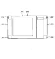
- FIG. 6 is a diagram corresponding to FIG. 5 of the packaging box of the second embodiment, and is a diagram for explaining a packaging box provided with a cut-and-raised portion on the upper side and cut-and-raised portions 261 and 262 on the lower side. is there.
- the description of the operations and effects common to the packaging box of the first embodiment is omitted, and the configurations, functions, and modifications different from those of the packaging box of the first embodiment are omitted. Only an example will be described.
- the packaging box of the second embodiment includes a top surface portion 250, a bottom surface portion 260 facing the top surface portion 250, and four side surface portions 271 and 272 located between the top surface portion 250 and the bottom surface portion 260.
- the bottom surface portion 260 also has an inner side flap and an outer side flap that is superimposed on the outside of the inner side flap.
- the arrangement structure of the plurality of cut and raised parts on the upper side of the packaging box of the second embodiment is the same as the arrangement structure of the plurality of cut and raised parts on the upper side of the packaging box of the first embodiment.
- the inner side flap of the bottom surface part 260 is located between the four side surface parts 271 and 272 and the heating cooker 201 as an object to be packed, like the inner side flap of the top surface part 250.
- a plurality of cut and raised portions 261 and 262 that can be cut and raised are provided.
- the number of cut and raised portions 212 and 222 formed on the inner flap of the top surface portion 250 and the number of cut and raised portions 261 and 262 formed on the inner flap of the bottom surface portion 260 are equal to each other. I'm doing it.
- the packaging box is formed on the inner flap of the top surface portion 250 when it is assembled into a rectangular parallelepiped shape without temporarily cutting and raising all the raised portions 212, 222, 261, 262.
- the plurality of cut-and-raised portions 212 and 222 and the plurality of cut-and-raised portions 261 and 262 formed on the inner flap of the bottom surface portion 260 are rectangular parallelepipeds in which all the cut-and-raised portions 212, 222, 261, and 262 are not cut and raised. It faces the height direction of the shaped packing box. Further, in this temporary rectangular parallelepiped packing box, a plurality of bent portions (connecting portions) of the plurality of raised portions 212 and 222 formed on the inner flap of the top surface portion 250 and a plurality of formed on the inner flap of the bottom surface portion 260. The bent portions (connection portions) of the cut and raised portions 261 and 262 are also opposed to each other in the height direction.
- the cut-and-raised portions 261 and 262 formed on the inner flap of the bottom surface portion 260 are cut into the cut-and-raised portions 261 and 262 in the state where the cut-and-raised portions 261 and 262 are cut and raised. Similar to the raising portions 212 and 222, they are positioned between the side surface of the heating cooker 201 and the side surfaces 271 and 272 of the packaging box.
- the plurality of cut-and-raised portions 261 and 262 are provided on the inner flaps of the bottom surface portion 260 so as to extend upward from the bottom surface portion 260 of the packaging box in a packed state. Therefore, the horizontal movement of the cooking device 201 can be restricted on the lower side of the cooking device 201. For this reason, it is not necessary to separately provide a cushioning material in the lower part of the heating cooker 201, the lower cushioning material can be omitted, or the cushioning material can be made small, and the height dimension of the packaging box can be reduced. Therefore, since the packaging box can be made small and compact, it is easy to carry, and more packaging boxes can be put in the container, and many packaging boxes can be transported at a time, thereby reducing transportation costs. .
- the material cost of the cushioning material can be reduced, and the packaging cost can be reduced.
- the outer side flaps of the bottom surface part 260 are overlapped with the outer side of the inner side flaps of the bottom surface part 260, so that the inner flaps of the bottom surface part 260 are cut and raised. Even if a hole is formed in the inner flap, there is no hole that communicates the outside and the inside of the packaging box. Therefore, foreign substances such as insects can be reliably prevented from entering from the outside to the inside of the packaging box, and the appearance of the packaging box can be prevented from being damaged.
- the cut-and-raised portion formed on the inner flap of the top surface portion may be formed on the inner flap of the bottom surface portion.
- the cut-and-raised portions 212 and 222 are formed on the inner flap of the top surface portion 250, and the cut-and-raised portions 261 and 262 are formed on the inner flap of the bottom surface portion 260.
- the cut and raised portion may be formed only on the inner side flap of the bottom surface portion without forming any cut and raised portion on the inner side flap of the surface portion.
- a packaging box having one or more cut-and-raised portions selected from the cut-and-raised portion described in the first embodiment and its modification and the cut-and-raised portion described in the second embodiment and its modification. Needless to say, it is included in the scope of the present invention.
Landscapes
- Engineering & Computer Science (AREA)
- Mechanical Engineering (AREA)
- Cartons (AREA)
- Packaging Of Machine Parts And Wound Products (AREA)
- Buffer Packaging (AREA)
Abstract
この梱包箱は、天面部と、底面部と、4つの側面部(71~74)とを備え、天面部は、内側フラップと、内側フラップの外側に重ね合わされる外側フラップとを有する。上記天面部の内側フラップに切り起こし部(111~114,121~124)を形成する。各切り起こし部(111~114,121~124)は、梱包状態で天面部の内側フラップから切り起こされるようになっている。各切り起こし部(111~114,121~124)は、切り起こされた状態で、側面部(71~74)と、加熱調理器との間に位置するようになっている。
Description
本発明は、製品を梱包する梱包箱に関する。
従来、梱包箱としては、製品の上部及び下部に緩衝材を嵌合したものを、内部に収納するものがある(特開平8-72938号公報、図8(特許文献1))。上記従来の梱包箱では、製品の上部及び下部に嵌合した緩衝材が、製品と梱包箱との間に位置して、製品の運搬時における外部からの衝撃などを吸収して製品を保護することによって、製品の破損を防止するようになっている。
しかしながら、上記従来の梱包箱では、製品の破損を防止できる一方、上記緩衝材が製品の上部及び下部に存在するため、梱包箱の他に、多量の緩衝材が必要で、梱包のコストが高いという問題がある。また、上記緩衝材によって、梱包箱が大型化して、運搬時にユーザが持ち運びにくくなるという問題がある。また、コンテナに入れることができる数が少なくなり、一度に輸送できる数が限られて、輸送のコストが高いという問題がある。
そこで、本発明の課題は、製品の運搬時における製品の破損を抑制できると共に、小型、コンパクトで、かつ、梱包および輸送のコストを低減できる梱包箱を提供することにある。
上記課題を解決するため、本発明の梱包箱は、
天面部と、
上記天面部と対向する底面部と、
上記天面部と上記底面部との間に位置する4つの側面部と
を備え、
上記天面部は、
内側フラップと、
上記内側フラップの外側に重ね合わされる外側フラップと
を有し、
上記内側フラップは、上記側面部と被梱包物との間に位置するように切り起こし可能な複数の切り起こし部を有することを特徴としている。
天面部と、
上記天面部と対向する底面部と、
上記天面部と上記底面部との間に位置する4つの側面部と
を備え、
上記天面部は、
内側フラップと、
上記内側フラップの外側に重ね合わされる外側フラップと
を有し、
上記内側フラップは、上記側面部と被梱包物との間に位置するように切り起こし可能な複数の切り起こし部を有することを特徴としている。
尚、この明細書で、上方や下方等の鉛直方向や、水平方向を示す文言を使用した場合、それらの文言は、上記梱包箱の底面が水平に設置されている状態での方向を表しているものとする。
本発明によれば、天面部の内側フラップが、側面部と被梱包物との間に位置するように切り起こし可能な複数の切り起こし部を有するから、切り起こし部を切り起こした状態で、切り起こし部を側面部と被梱包物との間に位置させることができる。このため、梱包箱に外部からの衝撃などが加えられても、切り起こし部が、被梱包物に接触することによって、衝撃を緩和でき、また、被梱包物の過度な移動を規制することができる。このように、上記切り起こし部を、緩衝部として機能させることができるから、被梱包物を保護できて、運搬時における上記被梱包物の破損を抑制できる。
また、上記複数の切り起こし部が天面部の内側フラップに設けられて、梱包状態で、梱包箱の天面部から下方へ向けて延在するようになるから、被梱包物の上部で、被梱包物の水平方向の移動を規制することができる。このため、上記被梱包物の上部に緩衝材を別途設ける必要がなく、この上部の緩衝材を省略することができ、あるいは緩衝材を小さくできて、梱包箱の高さ方向の寸法を低減できる。したがって、梱包箱を小型、コンパクトにすることができるから、持ち運びが容易になると共に、より多くの梱包箱をコンテナに入れて、一度に多くの梱包箱を輸送できて、輸送のコストを低減できる。
また、上記上部の緩衝材を省略することができるので、緩衝材の材料費を低減できて、梱包のコストを低減できる。
また、梱包状態において、天面部の外側フラップが、天面部の内側フラップの外側に重ね合わされるようになっているから、内側フラップの切り起こし部を切り起こして、内側フラップに穴を形成しても、梱包箱の外側と内側とを連通する穴が存在することがない。したがって、上記梱包箱の外側から内側へ、例えば虫などの異物が混入することを確実に防止できると共に、上記梱包箱の外観が損なわれることも防止できる。
一実施形態の梱包箱では、
上記内側フラップの上記切り起こし部は、
一方向に向いた上記側面部と上記被梱包物との間に位置するように切り起こされる第1の切り起こし部と、
上記一方向と交差する他方向に向いた上記側面部と上記被梱包物との間に位置するように切り起こされる第2の切り起こし部と
を含む。
上記内側フラップの上記切り起こし部は、
一方向に向いた上記側面部と上記被梱包物との間に位置するように切り起こされる第1の切り起こし部と、
上記一方向と交差する他方向に向いた上記側面部と上記被梱包物との間に位置するように切り起こされる第2の切り起こし部と
を含む。
上記実施形態によれば、上記第1の切り起こし部を切り起こした状態で、第1の切り起こし部が一方向に向いた側面部と被梱包物との間に位置するようになる。また、上記第2の切り起こし部を切り起こした状態で、第2の切り起こし部が上記一方向と交差する他方向に向いた側面部と被梱包物との間に位置するようになる。したがって、上記第1,第2の切り起こし部を、被梱包物に接触させて、被梱包物の過度な移動を上記一方向および上記他方向の2つの方向において規制することができるから、被梱包物をより確実に保護できて、運搬時における上記被梱包物の破損をより確実に抑制できる。
一実施形態の梱包箱では、
上記第1の切り起こし部は、上記内側フラップのコーナに設けられている。
上記第1の切り起こし部は、上記内側フラップのコーナに設けられている。
上記実施形態によれば、上記第1の切り起こし部は、上記内側フラップのコーナに設けられているから、内側フラップに1本の切り込みを設けるだけで、簡単に上記第2の切り起こし部を形成することができる。
また、本発明の梱包箱は、
天面部と、
上記天面部と対向する底面部と、
上記天面部と上記底面部との間に位置する4つの側面部と
を備え、
上記底面部は、
内側フラップと、
上記内側フラップの外側に重ね合わされる外側フラップと
を有し、
上記内側フラップは、上記側面部と被梱包物との間に位置するように切り起こし可能な複数の切り起こし部を有することを特徴としている。
天面部と、
上記天面部と対向する底面部と、
上記天面部と上記底面部との間に位置する4つの側面部と
を備え、
上記底面部は、
内側フラップと、
上記内側フラップの外側に重ね合わされる外側フラップと
を有し、
上記内側フラップは、上記側面部と被梱包物との間に位置するように切り起こし可能な複数の切り起こし部を有することを特徴としている。
本発明によれば、上記底面部の内側フラップが、側面部と被梱包物との間に位置するように切り起こし可能な複数の切り起こし部を有するから、上記切り起こし部を切り起こした状態で、切り起こし部を上記側面部と上記被梱包物との間に位置させることができる。このため、梱包箱に外部からの衝撃などが加えられても、上記切り起こし部が、上記被梱包物に接触することによって、衝撃を緩和でき、また、上記被梱包物の過度な移動を規制することができる。このように、上記切り起こし部を、緩衝部として機能させることができるから、上記被梱包物を保護できて、運搬時における上記被梱包物の破損を抑制できる。
また、上記複数の切り起こし部が底面部の内側フラップに設けられて、梱包状態で、上記梱包箱の底面部から上方へ向けて延在するようになるから、被梱包物の下部で、被梱包物の水平方向の移動を規制することができる。このため、被梱包物の下部に緩衝材を別途設ける必要がなく、下部の緩衝材を省略することができ、あるいは緩衝材を小さくできて、梱包箱の高さ方向の寸法を低減できる。したがって、梱包箱を小型、コンパクトにすることができるから、持ち運びが容易になると共に、より多くの梱包箱をコンテナに入れて、一度に多くの梱包箱を輸送できて、輸送のコストを低減できる。
また、上記下部の緩衝材を省略することができるので、緩衝材の材料費を低減できて、梱包のコストを低減できる。
また、梱包状態において、底面部の外側フラップが、底面部の内側フラップの外側に重ね合わされるようになっているから、底面部の内側フラップの切り起こし部を切り起こして、上記内側フラップに穴を形成しても、梱包箱の外側と内側とを連通する穴が存在することがない。したがって、梱包箱の外側から内側へ、例えば虫などの異物が混入することを確実に防止できると共に、梱包箱の外観が損なわれることも防止できる。
本発明によれば、梱包箱の側面部と被梱包物との間に、天面部および底面部のうちの少なくとも一方の内側フラップの切り起こし部が位置するようになるから、被梱包物の運搬時における被梱包物の破損を抑制できると共に、小型、コンパクトで、かつ、梱包および輸送のコストを低減できる梱包箱を提供することができる。
以下、本発明の梱包箱を図示の実施形態により詳細に説明する。
図1は、本発明の第1実施形態の梱包箱の梱包を説明するための斜視図であり、梱包箱の上蓋が開かれた状態の斜視図である。この梱包箱は、略一定の厚さを有する一枚のシート状の段ボール材から切り出して形成されている。
この梱包箱は、梱包状態で、天面部と、この天面部に高さ方向に対向する底面部60と、天面部と底面部60との間に位置する第1から第4の側面部71~74とを備える。上記天面部および底面部60のそれぞれの表面形状は、長辺と短辺とを有する長方形の形状を有している。天面部は、内側フラップ10と、内側フラップ10の外側に重ね合わされる外側フラップ20とを有している。尚、図1に示す梱包箱の状態では、梱包箱の上蓋が開かれていて、天面部が存在しない状態になっており、内側フラップ10および外側フラップ20の夫々は、梱包箱の外側に折り曲げられている。
上記第1から第4の側面部71~74は、鉛直方向下向きに見たとき、反時計回りに順番に位置している。上記第1の側面部71は、天面部の一方の短辺と、この短辺に対向する底面部60の一方の短辺との間に位置し、第3の側面部73は、天面部の他方の短辺と、底面部60の他方の短辺との間に位置している。また、上記第2の側面部72は、天面部の一方の長辺と、この長辺に対向する底面部60の一方の長辺との間に位置し、第4の側面部74は、天面部の他方の長辺と底面部60の他方の長辺との間に位置している。
この梱包箱内に、被梱包物の一例としての加熱調理器1を以下のように収納して梱包するようになっている。まず、上面に凹部が存在する第1,第2の底緩衝材61,62を用意する。次に、底面部60上に、上記凹部が上方に存在している状態で底面部60の一方の短辺に沿うように第1の底緩衝材61を配置する。また、第1の底緩衝材61に距離をおいて、上記凹部が上方に存在している状態で底面部60の他方の短辺に沿うように第2の底緩衝材62を配置する。上記第1,第2の底緩衝材61,62は、弾性を有する発泡スチロール等の合成樹脂の一体成型品からなっている。第1,第2の底緩衝材61,62の夫々の凹部は、加熱調理器1の底面部の形状に対応する形状になっている。
次に、上記加熱調理器1の底面部を第1,第2の底緩衝材61,62の凹部に嵌合する。このようにして、加熱調理器1を上記梱包箱の中に収納する。
最後に、内側フラップ10を内側に折り込んで閉じた後、図2以下を用いて説明する加熱調理器1の破損の抑制措置を行い、最後に外側フラップ20を内側に折り込んで、内側フラップ10の外側に外側フラップ20を重ね合わせる。このようにして、加熱調理器1を梱包する。なお、この梱包状態で、上記梱包箱は直方体に形成されるようになっている。
図2は、加熱調理器1を上記梱包箱に収納し、内側フラップ10および外側フラップ20が開いた状態を示す斜視図である。
図2に示すように、上記第1,第2底緩衝部材61,62の凹部に加熱調理器1の底面部を嵌合した状態で、底緩衝材61は、底面部60、第1の側面部71、第2の側面部72および第4の側面部74に当接するようになっている。同様に、上記第1,第2底緩衝部材61,62の凹部に加熱調理器1の底面部を嵌合した状態で、底緩衝材62は、底面部60、第2の側面部72、第3の側面部73および第4の側面部74に当接するようになっている。このため、加熱調理器1は、第1,第2の底緩衝材61,62によって保護されると共に、第1,第2の底緩衝材61,62を介して、底面部60および第1から第4の側面部71~74に対して位置決めされるようになっている。
図2に示すように、上記外側フラップ20は、第1の外側フラップ部21と、この第1の外側フラップ部21に対向する第2の外側フラップ部22とを有する。上記第1の外側フラップ部21は、長方形に形成され、第1の外側フラップ部21の一方の長辺と、上記第2の側面部72の上側の縁とは一致している。一方、上記第2の外側フラップ部22は、上記第1の外側フラップ部21と略同じ形状および大きさに形成され、第2の外側フラップ部22の一方の長辺と、上記第4の側面部74の上側の縁とは一致している。
一方、上記内側フラップ10は、第1の内側フラップ部11と、この第1の内側フラップ部11に対向する第2の内側フラップ部12とを有する。上記第1の内側フラップ部11は、長方形に形成され、第1の内側フラップ部11の一方の長辺と、上記第1の側面部71の上側の縁とは一致している。一方、上記第2の内側フラップ部12は、上記第1の内側フラップ部21と略同じ形状および大きさに形成され、第2の内側フラップ部12の一方の長辺と、上記第3の側面部73の上側の縁とは一致している。
上記第1,2の内側フラップ部11,12の夫々は、4つの略同一の大きさの略矩形状の切り起こし部を有している。上記梱包状態において、第1の内側フラップ部11の上記4つの切り起こし部と、第2の内側フラップ部12の上記4つの切り起こし部とは、上記梱包箱を天面部の長辺方向に垂直な方向に2等分する面に関して略面対称に配置されている。
図3は、第1の内側フラップ部11が開いた状態である一方、第2の内側フラップ部12が閉じた状態であり、かつ、切り起こし部が切り起こされる前の状態を示す図である。
図3に示すように、第2の内側フラップ部12の上記4つの切り起こし部である第1から第4の切り起こし部121~124は、反時計回りに位置している。上記第1から第4の切り起こし部121~124は、第2の内側フラップ部12を切り出して形成されている。
上記第1の切り起こし部121は、第2の内側フラップ部12の短辺方向の略中央に位置すると共に、一方向としての第2の内側フラップ部12の長辺方向に向いた第2の側面部72と、加熱調理器1との間に位置している。図3において、点線185は、実際には見えない加熱調理器1の側面を示している。上記第1の切り起こし部121のその延在方向に延在する一方の縁は、第2の側面部72に対向する加熱調理器1のその長手方向に延在する側面と重なっている。上記第1の切り起こし部121は、図中に点線で示す、第1の切り起こし部121の延在方向に直交する方向に延びる接続部121aで切り起こし可能になっている。この接続部121aは、第1の切り起こし部121の一部を画定している。上記第1の切り起こし部121は、接続部121aを支点にして切り起こされると、上記延在方向が底面部60に対して傾斜すると共に、第2の側面部72と、加熱調理器1のその長手方向に延在する側面との間に位置するようになっている。
上記第4の切り起こし部124は、第2の内側フラップ部12において、第1の切り起こし部121に対向するように設けられている。上記第4の切り起こし部124は、第2の内側フラップ部12の短辺方向の略中央に位置すると共に、第2の内側フラップ部12の長辺方向において、加熱調理器1と第4の側面部74との間に位置している。上記第4の切り起こし部124のその延在方向に延在する一方の縁は、第4の側面部74に対向する加熱調理器1の側面と重なっている。上記第4の切り起こし部124は、図中に点線で示す、第4の切り起こし部124の延在方向に直交する方向に延びる接続部124aで切り起こし可能になっている。この接続部124aは、第4の切り起こし部124の一部を画定している。上記第4の切り起こし部124は、接続部124aを支点にして切り起こされると、第4の切り起こし部124の延在方向が底面部60に対して傾斜すると共に、第4の側面部74と加熱調理器1のその長手方向に延在する側面部との間に位置するようになっている。
上記第2,第3の切り起こし部122,123は、第2の内側フラップ部12の長辺方向に沿って、互いに間隔をおいて位置すると共に、上記長辺方向と直交する他方向としての上記短辺方向に向いた第3の側面部73と、加熱調理器1との間に位置している。第2の切り起こし部122と、第3の切り起こし部123とは、第2の内側フラップ部12をその長辺方向に垂直な方向に2等分する面に関して略対称に配置されている。
上記第2の切り起こし部122のその延在方向に延在する一方の縁は、第3の側面部73に対向する加熱調理器1の側面と重なっている。上記第2の切り起こし部122は、図中に点線で示す、第2の切り起こし部122の延在方向に直交する方向に延びる接続部122aで切り起こし可能になっている。この接続部122aは、第2の切り起こし部122の一部を画定している。上記第2の切り起こし部122は、接続部122aを支点にして切り起こされると、第2の切り起こし部122の延在方向が底面部60に対して傾斜すると共に、第3の側面部73と加熱調理器1のその幅方向に延在する側面との間に位置するようになっている。
同様に、上記第3の切り起こし部123のその延在方向に延在する一方の縁は、第3の側面部73に対向する加熱調理器1のその幅方向に延在する側面と重なっている。上記第3の切り起こし部123は、図中に点線で示す、第3の切り起こし部123の延在方向に直交する方向に延びる接続部123aで切り起こし可能になっている。この接続部123aは、第3の切り起こし部123の一部を画定している。上記第3の切り起こし部123は、接続部123aを支点にして切り起こされると、第3の切り起こし部123の延在方向が底面部60に対して傾斜すると共に、第3の側面部73と加熱調理器1のその幅方向に延在する側面との間に位置するようになっている。上記第1から第4の切り起こし部121~124の延在方向における先端側の縁の両端のコーナは、面取りされている。
図4は、梱包状態での切り起こし部111~114,171~174の位置を示す上面図である。なお、図4では、第1,第2の外側フラップ部21,22の図示を省略している。
図4に示す状態では、第1の内側フラップ部11の第1から第4の切り起こし部111~114と、第2の内側フラップ部12の第1から第4の切り起こし部121~124とは、いずれも切り起こされて、天面部50に対して直交する方向に延在している。
第1の内側フラップ部11の第1の切り起こし部111と、第2の内側フラップ部12の第1の切り起こし部121とは、加熱調理器1の長手方向の延在部と、第2の側面部72との間に位置している。また、第1の切り起こし部111,121の延在方向に直交する方向の一方の縁は、第2の側面部72と対向する加熱調理器1の側面に接触している。
同様に、第1の内側フラップ部11の第4の切り起こし部114と、第2の内側フラップ部12の第4の切り起こし部124とは、加熱調理器1と第4の側面部74との間に位置している。また、第4の切り起こし部114,124のその延在方向に延在する一方の縁は、第4の側面部74と対向する加熱調理器1のその長手方向に延在する側面に接触している。
一方、第1の内側フラップ部11の第2,第3の切り起こし部112,113は、加熱調理器1のその幅方向に延在する側面と第1の側面部71との間に位置している。また、第2,第3の切り起こし部112,113の夫々は、各延在方向に延在する一方の縁で、第1の側面部71と対向する加熱調理器1のその幅方向に延在する側面に接触している。
同様に、第2の内側フラップ部12の第2,第3の切り起こし部122,123は、加熱調理器1のその幅方向に延在する側面と第3の側面部73との間に位置している。また、第2,第3の切り起こし部122,123の夫々は、各延在方向に延在する一方の縁で、第3の側面部73と対向する加熱調理器1のその幅方向に延在する側面に接触している。
なお、穴部161~164は、第1の内側フラップ部11の第1から第4の切り起こし部111~114が切り起こされることにより形成されたものである。同様に、穴部171~174は、第2の内側フラップ部12の第1から第4の切り起こし部121~124が切り起こされることにより形成されたものである。
上記第1の内側フラップ部11の先端側の縁と、第2の内側フラップ部12の先端側の縁とは、梱包状態で、一定の距離をおいて位置している。一方、上記第1の外側フラップ部21の先端側の縁と、第2の外側フラップ部22の先端側の縁とは、梱包状態で接触するようになっており、これらの縁は、天面部の短辺方向の中心線L上に位置している。第1,第2の外側フラップ部21,22は、第1,第2の内側フラップ部11,12を覆うと共に、第1の内側フラップ部11と第2の内側フラップ部12との間の開口の全てを覆うようになっている。
図5は、梱包状態の梱包箱を、高さ方向および梱包箱の長手方向を含む図4にAA線で示す平面で切断したときの断面図である。
図5に示すように、上記第2の切り起こし部112は、加熱調理器1と第1の側面部71との間に位置している。また、第2の切り起こし部112のその延在方向に延在する一方の縁は、加熱調理器1の側面に接触する一方、第2の切り起こし部112の延在方向の他方の縁は、第1の側面部71と一定の距離をおいて位置している。
同様に、上記第2の切り起こし部122は、加熱調理器1と第3の側面部73との間に位置している。また、第2の切り起こし部122のその延在方向に延在する一方の縁は、加熱調理器1の側面に接触する一方、第2の切り起こし部122の延在方向の他方の縁は、第3の側面部73と一定の距離をおいて位置している。
図5に示すように、梱包箱の天面部50は、加熱調理器1の上面に対して、ほとんど距離をあけることなく鉛直方向に対向している。また、天面部50と、加熱調理器1の上面との間に、如何なる部材も配置しないようになっている。
また、図5に示すように、上記第1の底緩衝材61は、第1の側面部71と対向する加熱調理器1の側面と、加熱調理器1の底面とに当接する一方、上記第2の底緩衝材62は、第3の側面部73と対向する加熱調理器1の側面と、加熱調理器1の底面とに当接している。
上記構成の梱包箱によれば、上記内側フラップ10は、第1から第4の側面部71~74と加熱調理器1との間に位置するように切り起こし可能な第1から第4の切り起こし部111~114,121~124を有するから、上記第1から第4の切り起こし部111~114,121~124を切り起こした状態で、第1から第4の切り起こし部111~114,121~124を、第1から第4の側面部71~74と、加熱調理器1との間に位置させることができる。このため、梱包箱に外部からの衝撃などが加えられても、第1から第4の切り起こし部111~114,121~124が、加熱調理器1に接触することによって、加熱調理器1の衝撃を緩和でき、また、加熱調理器1の過度な移動を規制することができる。このように、第1から第4の切り起こし部111~114,121~124を、緩衝部として機能させることができるから、加熱調理器1を保護できて、運搬時における加熱調理器1の破損を抑制できる。
また、上記第1から第4の切り起こし部111~114,121~124が内側フラップ10に設けられて、梱包状態で、上記梱包箱の天面部50から下方へ向けて延在するようになるから、加熱調理器1の上部で、加熱調理器1の水平方向の移動を規制することができる。このため、加熱調理器1の上部に緩衝材を別途設ける必要がなく、この上部の緩衝材を省略することができ、あるいは緩衝材を小さくできて、梱包箱の高さ方向の寸法を低減できる。したがって、梱包箱を小型、コンパクトにすることができるから、持ち運びが容易になると共に、より多くの梱包箱をコンテナに入れて、一度に多くの梱包箱を輸送できて、輸送のコストを低減できる。
また、上記上部の緩衝材を省略することができるので、緩衝材の材料費を低減できて、梱包のコストを低減できる。
また、梱包状態において、上記外側フラップ20が、内側フラップ10の外側に重ね合わされるようになっているから、内側フラップ10の第1から第4の切り起こし部111~114,121~124を切り起こして、内側フラップ10に穴部161~164,171~174を形成しても、上記梱包箱の外側と内側とを連通する穴が存在することがない。したがって、上記梱包箱の外側から内側へ、例えば虫などの異物が混入することを確実に防止できると共に、上記梱包箱の外観が損なわれることも防止できる。
また、上記第1の切り起こし部121を切り起こした状態で、第1の切り起こし部121が第2の内側フラップ部12の長辺方向に向いた第2の側面部72と加熱調理器1との間に位置するようになる。また、上記第2の切り起こし部122を切り起こした状態で、第2の切り起こし部122が上記長辺方向と直交する方向に向いた第3の側面部73と加熱調理器1との間に位置するようになる。したがって、上記第1,第2の切り起こし部121,122を、加熱調理器1に接触させて、加熱調理器1の過度な移動を上記長辺方向および上記長辺方向と直交する方向の2つの方向において規制することができるから、加熱調理器1をより確実に保護できて、運搬時における加熱調理器1の破損をより確実に抑制できる。
また、上記梱包状態において、第1から第4の切り起こし部111~114,121~124が、第1から第4の側面部71~74と加熱調理器1との間に位置している。したがって、第1から第4の切り起こし部111~114,121~124を加熱調理器1に接触させて、加熱調理器1の過度な移動を、4つの方向において規制することができるから、加熱調理器1をより確実に保護できて、運搬時における加熱調理器1の破損を確実に抑制できる。
また、上記梱包状態で、第1の内側フラップ部11の第1の切り起こし部111が、加熱調理器1と第2の側面部72との間に位置する一方、第1の内側フラップ部11の第4の切り起こし部114が、加熱調理器1と第4の側面部74との間に位置するようになる。同様に、第2の内側フラップ部12の第1の切り起こし部121が、加熱調理器1と第2の側面部72との間に位置する一方、第2の内側フラップ部12の第4の切り起こし部124が、加熱調理器1と第4の側面部74との間に位置するようになる。このため、第2の側面部72と、第4の側面部74とが対向する方向における加熱調理器1の移動をより一層規制して、加熱調理器1をより確実に保護することができる。したがって、運搬時における、加熱調理器1の破損をより確実に抑制できる。
また、上記梱包状態で、上記第1から第4の切り起こし部111~114,121~124は、それぞれ、加熱調理器1の側面に接触するようになっているから、第1から第4の切り起こし部111~114,121~124によって、加熱調理器1の移動を防止できて、加熱調理器1を確実に保護できる。また、第1から第4の切り起こし部111~114,121~124で、加熱調理器1を保持できるから、加熱調理器1の位置決めをすることもできる。
また、各切り起こし部111~114,121~124の延在方向における先端側の縁の両端のコーナが、面取りされているから、切り起こし部111~114,121~124の切り起こしが容易になる。
上記第1実施形態では、第1の内側フラップ部11が、第1,第2,第4の側面部71,72,74と加熱調理器1との間に位置するように、切り起こし可能な切り起こし部111~114を有すると共に、第2の内側フラップ部12が、第2~第4の側面部72~74と加熱調理器1との間に位置するように、切り起こし可能な切り起こし部121~124を有していた。しかしながら、この発明では、内側フラップは、少なくとも1つの側面部と被梱包物との間に位置するように切り起こし可能な複数の切り起こし部を有していれば良い。
また、上記第1実施形態では、上記第1の切り起こし部122は、第2の内側フラップのコーナに設けられていなかったが、この発明では、第1の切り起こし部が、内側フラップのコーナに設けられていてもよい。この場合、第1の切り起こし部が、内側フラップのコーナに設けられているから、内側フラップに1本の切り込みを設けるだけで、簡単に第1の切り起こし部を形成することができる。
また、上記第1実施形態では、梱包状態で、上記各切り起こし部111~114,121~124が、加熱調理器1と、第1から第4の側面部71~74との間に位置し、2つの切り起こし部が、加熱調理器1と、各側面部との間にそれぞれ位置するようになっていた。しかしながら、この発明では、2つの切り起こし部が、被梱包物といずれかの側面部との間に位置するようになっていてもよく、3つ以上の切り起こし部が、被梱包物といずれかの側面部との間に位置するようになっていてもよい。
また、上記第1実施形態では、梱包状態で、上記各切り起こし部111~114,121~124が、加熱調理器1の側面に接触するようになっていたが、この発明では、少なくとも1つの切り起こし部が、被梱包物の側面に接触するようになっていてもよい。
また、上記第1実施形態では、梱包状態で、上記各切り起こし部111~114,121~124が、第1から第4の側面部71~74と一定の距離をおいて位置していたが、この発明では、少なくとも1つの切り起こし部が、側面部に接触するようになっていてもよい。この場合、切り起こし部が、側面部に接触するようになっているから、側面部によって、切り起こし部をサポートすることができて、切り起こし部の剛性が高くなって、切り起こし部が変形しにくくなる。したがって、被梱包物をより確実に保護することができて、運搬時における、被梱包物の破損をより確実に抑制することができる。
また、上記第1実施形態では、切り起こす前の各切り起こし部111,114,121,124が、第1,第2の内側フラップ部11,12の短辺方向の略中央に位置していたが、この発明では、切り起こし部が、略中央ではなく、例えば、少なくとも1つの切り起こし部が、第1の内側フラップ部および第2の内側フラップ部のうちの少なくとも一方の短辺方向の端部に位置していてもよい。
また、上記第1実施形態では、切り起こす前の上記各切り起こし部111~114,121~124の各々の延在方向に延在する一方の縁が、加熱調理器1の側面と重なっていたが、この発明では、少なくとも1つの切り起こし部において、その少なくとも1つの切り起こし部の延在方向に延在する両方の縁が、被梱包物の側面と重なっていなくてもよい。
また、上記第1実施形態では、切り起こす前に切り起こし部の延在方向に直交する方向に対向する二つの切り起こし部の延在方向は全て同一であったが、この発明では、切り起こす前に切り起こし部の延在方向に直交する方向に対向する二つの切り起こし部の延在方向は異なっていても良い。
また、上記第1実施形態では、上記梱包状態において、第1の内側フラップ部11の切り起こし部111~114と、第2の内側フラップ部12の切り起こし部121~124とは、梱包箱を天面部50の長辺方向に垂直な方向に2等分する面に対して略面対称に配置されていたが、この発明では、梱包箱を天面部の長辺方向に垂直な方向に2等分する面に対して、略対称でなくてもよく、ランダムに配置されていてもよい。
また、上記第1実施形態では、上記第1から第4の切り起こし部111~114,121~124の表面積は、略同一の大きさであったが、この発明では、少なくとも1つの切り起こし部の表面積の大きさは、他の切り起こし部の表面積の大きさよりも大きくてもよい。
また、上記第1実施形態では、上記第1から第4の切り起こし部111~114,121~124の形状は、略矩形状であったが、この発明では、少なくとも1つの切り起こし部の形状は、例えば台形形状や、三角形状、半円形状等の矩形状以外の形状でもよい。
また、上記第1実施形態では、上記第1から第4の切り起こし部111~114,121~124の上記延在方向における先端側の縁の両端のコーナが面取りされていたが、この発明では、切り起こし部の延在方向における先端側の縁の両端のコーナが面取りされていなくてもよく、例えば、切り起こし部の延在方向における先端側の縁の中央部が円弧状に切り欠かれていてもよい。
また、上記第1実施形態では、上記内側フラップ10は、互いに対向する2つの部分、つまり、第1,第2の内側フラップ部11,12を有していたが、この発明では、内側フラップは、1つの部分からなっていてもよく、内側フラップの縁が、一の側面部のみの上側の縁と一致していてもよい。同様に、上記外側フラップ20は、互いに対向する2つの部分、つまり、第1,第2の外側フラップ部21,22を有していたが、この発明では、外側フラップは、1つの部分からなっていてもよく、外側フラップの縁が、一の側面部のみの上側の縁と一致していてもよい。
また、上記第1実施形態では、第1,第2の内側フラップ部11,12は、略同じ大きさに形成されていたが、この発明では、第1,第2の内側フラップ部は、略同じ大きさでなくてもよく、例えば、第1の内側フラップ部が第2の内側フラップ部よりも大きくてもよい。同様に、上記第1実施形態では、第1,第2の外側フラップ部21,22は、略同じ大きさに形成されていたが、この発明では、第1,第2の外側フラップ部は、同じ大きさでなくてもよく、例えば、第1の外側フラップ部が第2の外側フラップ部よりも大きくてもよい。
また、上記第1実施形態では、上記第1の内側フラップ部11の先端側の縁と、第2の内側フラップ部12の先端側の縁とは、梱包状態で、一定の距離をおいて位置していたが、この発明では、第1の内側フラップの先端側の縁と、第2の内側フラップの先端側の縁とは、梱包状態で、接触していてもよい。
また、上記第1実施形態では、上記第1の内側フラップ部11は、長方形に形成され、第1の内側フラップ部11の一方の長辺と、上記第1の側面部71の上側の縁とは一致していた。しかしながら、この発明では、第1の内側フラップの一方の短辺と、側面部の上側の縁とが一致していてもよい。同様に、上記第2の内側フラップ部12は、長方形に形成され、第2の内側フラップ部12の一方の長辺と、上記第3の側面部73の上側の縁とは一致していたが、この発明では、第2の内側フラップの一方の短辺と、側面部の上側の縁とが一致していてもよい。
また、上記第1実施形態では、第1,第2の内側フラップ部11,12の縁は、梱包箱のその幅方向に延在する側面部71,73の上側の縁と一致していたが、この発明では、第1,第2の内側フラップの縁は、梱包箱のその長手方向に延在する側面部の上側の縁と一致していてもよい。同様に第1,第2の外側フラップ部21,22の縁は、梱包箱のその長手方向に延在する側面部72,74の上側の縁と一致していたが、この発明では、第1,第2の外側フラップの縁は、梱包箱のその幅方向に延在する側面部の上側の縁と一致していてもよい。
また、上記第1実施形態では、上記第1,第2の内側フラップ部11,12および第1,第2の外側フラップ部21,22は、長方形に形成されていたが、この発明では、第1,第2の内側フラップおよび第1,第2の外側フラップは、長方形以外の形状、例えば、正方形や、台形などの形状に形成されていてもよい。
また、上記第1実施形態では、梱包状態で、天面部50と、加熱調理器1の上面との間には、何も設けられていなかったが、天面部と、被梱包物の上面との間に、気泡緩衝材(プチプチ)や、フェルトやスポンジ等の弾性を有する材質からなるシート状部材等、シート状の緩衝材が設けられていてもよい。
また、上記第1実施形態では、梱包状態で、天面部50と、加熱調理器1の上面との間には、何も設けられていなかった。しかしながら、この発明では、切り起こし後の切り起こし部が、梱包状態で、天面部と、被梱包物の上面との間の隙間を埋めるように位置する切り起こし部を、内側フラップに設けることもできる。そして、このようにすると、被梱包物の上方の衝撃をやわらげることができると共に、天面部と被梱包物の上面との間に如何なるシート状の緩衝材も設ける必要がないようにすることができる。
また、上記第1実施形態では、上記梱包箱は、一定板厚を有する一枚のシート状の段ボール材から切り出して形成されていたが、この発明では、梱包箱の全部または一部が、木材や合成樹脂、金属等の板部材からなってもよい。
また、上記第1実施形態では、上記梱包箱が、加熱調理器1を梱包していたが、この発明の梱包箱は、パーソナルコンピュータ、家庭用電話、携帯電話、複写機、ビデオカメラ、デジタルカメラ、電子辞書、カーナビゲーションシステム、AV(Audio Visual)機器、洗濯機、冷蔵庫、炊飯器、食器洗い機、掃除機、エアコン等、如何なる製品を梱包するためのものであっても良い。
また、上記第1実施形態およびその変形例で説明した梱包箱の上部側の切り起こし部の構成を、そのまま梱包箱の下部側で実現しても良いことは勿論である。
図6は、第2実施形態の梱包箱の図5に対応する図であり、上側に切り起こし部を設けると共に、下側にも切り起こし部261,262を設けた梱包箱を説明する図である。
尚、第2実施形態の梱包箱では、第1実施形態の梱包箱と共通の作用効果および変形例については説明を省略することにし、第1実施形態の梱包箱と異なる構成、作用効果および変形例についてのみ説明を行うことにする。
第2実施形態の梱包箱は、天面部250と、天面部250と対向する底面部260と、天面部250と底面部260との間に位置する4つの側面部271,272とを備え、天面部250に加えて底面部260も、内側フラップと、内側フラップの外側に重ね合わされる外側フラップとを有する。第2実施形態の梱包箱の上方側における複数の切り起こし部の配置構造は、上記第1実施形態の梱包箱の上方側における複数の切り起こし部の配置構造と同一になっている。また、この梱包箱は、底面部260の内側フラップが、天面部250の内側フラップと同様に、4つの側面部271,272と被梱包物としての加熱調理器201との間に位置するように切り起こし可能な複数の切り起こし部261,262を有する。
第2実施形態の梱包箱においては、天面部250の内側フラップに形成した切り起こし部212,222の数と、底面部260の内側フラップに形成した切り起こし部261,262の数とは、一致している。また、第2実施形態の梱包箱においては、梱包箱を、全ての切り起こし部212,222,261,262を仮に切り起こさないで直方体状に組み立てたとき、天面部250の内側フラップに形成した複数の切り起こし部212,222と、底面部260の内側フラップに形成した複数の切り起こし部261,262とが、その全ての切り起こし部212,222,261,262が切り起こされていない直方体状の梱包箱の高さ方向に対向するようになっている。また、この仮の直方体状の梱包箱において、天面部250の内側フラップに形成した複数の切り起こし部212,222の夫々の折り曲げ部(接続部)と、底面部260の内側フラップに形成した複数の切り起こし部261,262の夫々の折り曲げ部(接続部)とも、上記高さ方向に対向するようになっている。
図6に示すように、底面部260の内側フラップに形成された各切り起こし部261,262は、その切り起こし部261,262が切り起こされた状態で、天面部250に形成された各切り起こし部212,222と同様に、加熱調理器201の側面と、梱包箱の側面271,272との間に位置するようになっている。
上記第2実施形態によれば、上記複数の切り起こし部261,262が底面部260の内側フラップに設けられて、梱包状態で、梱包箱の底面部260から上方へ向けて延在するようになるから、加熱調理器201の下方側で、加熱調理器201の水平方向の移動を規制することができる。このため、加熱調理器201の下部に緩衝材を別途設ける必要がなく、下部の緩衝材を省略することができ、あるいは緩衝材を小さくできて、梱包箱の高さ方向の寸法を低減できる。したがって、梱包箱を小型、コンパクトにすることができるから、持ち運びが容易になると共に、より多くの梱包箱をコンテナに入れて、一度に多くの梱包箱を輸送できて、輸送のコストを低減できる。
また、上記下部の緩衝材を省略することができるので、緩衝材の材料費を低減できて、梱包のコストを低減できる。
また、梱包状態において、底面部260の外側フラップが、底面部260の内側フラップの外側に重ね合わされるようになっているから、底面部260の内側フラップの切り起こし部261,262を切り起こして、上記内側フラップに穴を形成しても、梱包箱の外側と内側とを連通する穴が存在することがない。したがって、梱包箱の外側から内側へ、例えば虫などの異物が混入することを確実に防止できると共に、梱包箱の外観が損なわれることも防止できる。
尚、上記第1実施形態およびその変形例において、天面部の内側フラップに形成した切り起こし部を、底面部の内側フラップに形成しても良いことは、勿論である。
また、上記第2実施形態では、天面部250の内側フラップに切り起こし部212,222を形成すると共に、底面部260の内側フラップに切り起こし部261,262を形成したが、この発明では、天面部の内側フラップに切り起こし部を一切形成しないで、底面部の内側フラップのみに切り起こし部を形成しても良い。
尚、上記第1実施形態およびその変形例で説明した切り起こし部と、第2実施形態およびその変形例で説明した切り起こし部とのうちから選択した一以上の切り起こし部を有する梱包箱が、この発明の範疇に含まれることは言うまでもない。
1,201 加熱調理器
10 内側フラップ
11 第1の内側フラップ部
12 第2の内側フラップ部
20 外側フラップ
21 第1の外側フラップ部
22 第2の外側フラップ部
50,250 天面部
60,260 底面部
71 第1の側面部
72 第2の側面部
73 第3の側面部
74 第4の側面部
111,121 第1の切り起こし部
112,122 第2の切り起こし部
113,123 第3の切り起こし部
114,124 第4の切り起こし部
212,222 天面部の内側フラップに形成された切り起こし部
261,262 底面部の内側フラップに形成された切り起こし部
271,273 第2実施形態の梱包箱の側面部
10 内側フラップ
11 第1の内側フラップ部
12 第2の内側フラップ部
20 外側フラップ
21 第1の外側フラップ部
22 第2の外側フラップ部
50,250 天面部
60,260 底面部
71 第1の側面部
72 第2の側面部
73 第3の側面部
74 第4の側面部
111,121 第1の切り起こし部
112,122 第2の切り起こし部
113,123 第3の切り起こし部
114,124 第4の切り起こし部
212,222 天面部の内側フラップに形成された切り起こし部
261,262 底面部の内側フラップに形成された切り起こし部
271,273 第2実施形態の梱包箱の側面部
Claims (4)
- 天面部(50)と、
上記天面部(50)と対向する底面部(60)と、
上記天面部(50)と上記底面部(60)との間に位置する4つの側面部(71~74)と
を備え、
上記天面部(50)は、
内側フラップ(10)と、
上記内側フラップ(10)の外側に重ね合わされる外側フラップ(20)と
を有し、
上記内側フラップ(10)は、上記側面部(71~74)と被梱包物(1)との間に位置するように切り起こし可能な複数の切り起こし部(111~114,121~124)を有することを特徴とする梱包箱。 - 請求項1に記載の梱包箱において、
上記内側フラップ(10)の上記切り起こし部(111~114,121~124)は、
一方向に向いた上記側面部(72)と上記被梱包物(1)との間に位置するように切り起こされる第1の切り起こし部(111,121)と、
上記一方向と交差する他方向に向いた上記側面部(71,73)と上記被梱包物(1)との間に位置するように切り起こされる第2の切り起こし部(112,122)と
を含むことを特徴とする梱包箱。 - 請求項2に記載の梱包箱において、
上記第1の切り起こし部は、上記内側フラップのコーナに設けられていることを特徴とする梱包箱。 - 天面部(250)と、
上記天面部(250)と対向する底面部(260)と、
上記天面部(250)と上記底面部(260)との間に位置する4つの側面部(271,273)と
を備え、
上記底面部(260)は、
内側フラップと、
上記内側フラップの外側に重ね合わされる外側フラップと
を有し、
上記内側フラップは、上記側面部(271,273)と被梱包物(201)との間に位置するように切り起こし可能な複数の切り起こし部(261,262)を有することを特徴とする梱包箱。
Applications Claiming Priority (2)
| Application Number | Priority Date | Filing Date | Title |
|---|---|---|---|
| JP2011072587A JP2014114014A (ja) | 2011-03-29 | 2011-03-29 | 梱包箱 |
| JP2011-072587 | 2011-03-29 |
Publications (1)
| Publication Number | Publication Date |
|---|---|
| WO2012133053A1 true WO2012133053A1 (ja) | 2012-10-04 |
Family
ID=46930785
Family Applications (1)
| Application Number | Title | Priority Date | Filing Date |
|---|---|---|---|
| PCT/JP2012/057202 Ceased WO2012133053A1 (ja) | 2011-03-29 | 2012-03-21 | 梱包箱 |
Country Status (2)
| Country | Link |
|---|---|
| JP (1) | JP2014114014A (ja) |
| WO (1) | WO2012133053A1 (ja) |
Citations (6)
| Publication number | Priority date | Publication date | Assignee | Title |
|---|---|---|---|---|
| US2163045A (en) * | 1938-03-14 | 1939-06-20 | Anchor Hocking Glass Corp | Carton and blank therefor |
| US2790588A (en) * | 1953-08-07 | 1957-04-30 | Owens Illinois Glass Co | Shipping containers |
| JPS5096123U (ja) * | 1973-12-29 | 1975-08-12 | ||
| JPS51100232U (ja) * | 1975-02-07 | 1976-08-11 | ||
| JPH0549614U (ja) * | 1991-11-30 | 1993-06-29 | 株式会社フタバ化学 | 包装容器 |
| JP2006117252A (ja) * | 2004-10-19 | 2006-05-11 | Funai Electric Co Ltd | 梱包材 |
-
2011
- 2011-03-29 JP JP2011072587A patent/JP2014114014A/ja not_active Withdrawn
-
2012
- 2012-03-21 WO PCT/JP2012/057202 patent/WO2012133053A1/ja not_active Ceased
Patent Citations (6)
| Publication number | Priority date | Publication date | Assignee | Title |
|---|---|---|---|---|
| US2163045A (en) * | 1938-03-14 | 1939-06-20 | Anchor Hocking Glass Corp | Carton and blank therefor |
| US2790588A (en) * | 1953-08-07 | 1957-04-30 | Owens Illinois Glass Co | Shipping containers |
| JPS5096123U (ja) * | 1973-12-29 | 1975-08-12 | ||
| JPS51100232U (ja) * | 1975-02-07 | 1976-08-11 | ||
| JPH0549614U (ja) * | 1991-11-30 | 1993-06-29 | 株式会社フタバ化学 | 包装容器 |
| JP2006117252A (ja) * | 2004-10-19 | 2006-05-11 | Funai Electric Co Ltd | 梱包材 |
Also Published As
| Publication number | Publication date |
|---|---|
| JP2014114014A (ja) | 2014-06-26 |
Similar Documents
| Publication | Publication Date | Title |
|---|---|---|
| JP2003063569A (ja) | 梱包用緩衝材および梱包物 | |
| US20120031807A1 (en) | Shock Absorbing Member and Shock Absorbing Structure | |
| US12240665B2 (en) | Packing box and cardboard structure | |
| KR102781877B1 (ko) | 포장용 완충 구조체 | |
| CN208181781U (zh) | 板状物输送容器 | |
| WO2012133053A1 (ja) | 梱包箱 | |
| JP2012086868A (ja) | 梱包装置用支持部材及びそれを用いた梱包装置 | |
| JP6119675B2 (ja) | 梱包材 | |
| JP5773534B2 (ja) | 包装ケース | |
| JP6076229B2 (ja) | 包装緩衝部材およびそれを備えた包装材 | |
| CN103434755B (zh) | 缓冲包装单元及缓冲包装箱 | |
| JP7624578B2 (ja) | 温水装置の包装構造 | |
| JP3189470U (ja) | 梱包材、梱包構造及び梱包体 | |
| JP3983073B2 (ja) | 梱包用緩衝材および梱包箱 | |
| JP4481766B2 (ja) | 梱包構造 | |
| CN217321229U (zh) | 一种纸箱 | |
| JP4338531B2 (ja) | 包装装置 | |
| KR20140100599A (ko) | 엘씨디 필름의 에지와 코너의 불량방지구조로 이루어진 포장상자 | |
| CN202642503U (zh) | 包装用承块组件 | |
| JP5629806B2 (ja) | 梱包材 | |
| CN101269730A (zh) | 包装物以及缓冲角垫 | |
| JP2017178336A (ja) | 梱包材 | |
| JP2025019796A (ja) | 緩衝材及び緩衝材付き被梱包体 | |
| JP6468238B2 (ja) | 梱包材 | |
| JP6033168B2 (ja) | 緩衝部材 |
Legal Events
| Date | Code | Title | Description |
|---|---|---|---|
| 121 | Ep: the epo has been informed by wipo that ep was designated in this application |
Ref document number: 12765801 Country of ref document: EP Kind code of ref document: A1 |
|
| NENP | Non-entry into the national phase |
Ref country code: DE |
|
| 122 | Ep: pct application non-entry in european phase |
Ref document number: 12765801 Country of ref document: EP Kind code of ref document: A1 |
|
| NENP | Non-entry into the national phase |
Ref country code: JP |