WO2012132865A1 - 突出部高さ測定装置及び方法 - Google Patents
突出部高さ測定装置及び方法 Download PDFInfo
- Publication number
- WO2012132865A1 WO2012132865A1 PCT/JP2012/056336 JP2012056336W WO2012132865A1 WO 2012132865 A1 WO2012132865 A1 WO 2012132865A1 JP 2012056336 W JP2012056336 W JP 2012056336W WO 2012132865 A1 WO2012132865 A1 WO 2012132865A1
- Authority
- WO
- WIPO (PCT)
- Prior art keywords
- illumination
- imaging
- light
- height
- unit
- Prior art date
- Legal status (The legal status is an assumption and is not a legal conclusion. Google has not performed a legal analysis and makes no representation as to the accuracy of the status listed.)
- Ceased
Links
Images





Classifications
-
- G—PHYSICS
- G01—MEASURING; TESTING
- G01B—MEASURING LENGTH, THICKNESS OR SIMILAR LINEAR DIMENSIONS; MEASURING ANGLES; MEASURING AREAS; MEASURING IRREGULARITIES OF SURFACES OR CONTOURS
- G01B11/00—Measuring arrangements characterised by the use of optical techniques
- G01B11/24—Measuring arrangements characterised by the use of optical techniques for measuring contours or curvatures
- G01B11/245—Measuring arrangements characterised by the use of optical techniques for measuring contours or curvatures using a plurality of fixed, simultaneously operating transducers
-
- G—PHYSICS
- G01—MEASURING; TESTING
- G01B—MEASURING LENGTH, THICKNESS OR SIMILAR LINEAR DIMENSIONS; MEASURING ANGLES; MEASURING AREAS; MEASURING IRREGULARITIES OF SURFACES OR CONTOURS
- G01B11/00—Measuring arrangements characterised by the use of optical techniques
- G01B11/02—Measuring arrangements characterised by the use of optical techniques for measuring length, width or thickness
- G01B11/06—Measuring arrangements characterised by the use of optical techniques for measuring length, width or thickness for measuring thickness ; e.g. of sheet material
Definitions
- the present invention relates to a protrusion height measuring device that measures the height of a plurality of protrusions distributed on a substrate plane protruding from the plane, in particular, the height of a bump formed on a semiconductor device including a BGA, and the like. Regarding the method.
- a bump is formed by placing a solder ball on the terminal on the back of the package, the back of the package is brought into contact with the mounting target substrate, and the bump (ball-shaped solder) is reflowed or the like.
- Mounting is performed by heating and soldering the wiring land portion on the mounting target substrate.
- bumps are formed on the package, but the process margin at the time of bump formation is small, and it is difficult to form bumps of uniform height. Therefore, bumps having different heights may be formed individually. Under such circumstances, if some bumps are extracted and the height is measured and the heights of other bumps are estimated, an inappropriate case occurs. In order to eliminate such inappropriateness, it is required to measure the height of all the bumps. In addition, the number of bumps per chip and wafer is increasing due to the density of bumps, but the processing time for measuring the bumps applied to the wafer is required to be as short as possible. For this reason, it is required to measure the height of all the bumps in a shorter time.
- the relative height flatness (coplanarity) of the top of each head is important, but not only that, it is also required to measure the height from the base surface of the package. This is because in the mounting of a chip using small-diameter and dense bumps, the permissible width for the variation in bump height is small with respect to the gap amount (gap amount) between the chip and the substrate at the time of mounting.
- the autofocus method measures the height of a bump by focusing on the bump according to the principle of autofocus. Focusing and bump height measurement are sequentially performed for each bump. That is, a chip or wafer with bumps to be measured is mounted on an XY table, and the XY table is moved by a minute amount so that one bump on the package is positioned directly below the optical axis of the optical system, and focusing is performed. A series of operations such as measuring the bump height is repeated for each bump (for example, Patent Document 1).
- the measurement time increases as the number of bumps increases. For example, there are cases where there are 2 million or more IC bumps of a wafer level package (WLP), which is a kind of CSP package, on a wafer with a diameter of 300 mm. In this measurement, 0.2 mm is required for one movement of the XY table. If it takes 1 second to focus once, it takes 462 hours or more to measure all the bumps on one wafer. This measurement time is not realistic in an actual production site.
- WLP wafer level package
- Stereo camera method In the stereo camera method, the bump is irradiated with light, the reflected light from the bump head is photographed by a plurality of cameras, the positions are extracted, and the bump top is determined from the difference in coordinate position. Find the coordinates.
- a two-dimensional camera imaging unit
- CMOS complementary metal-oxide-semiconductor
- a plurality of bumps existing in a predetermined range can be imaged at a time and the respective heights can be obtained (for example, Patent Documents). 2-5).
- optical cutting method laser slit light is projected by a laser slit light projection device at an angle with respect to the measurement target (for example, 45 ° when the vertical direction of the measurement target is 0 °), and the inspection object is inspected.
- reflected light from the laser slit light generated in the part is imaged by an imaging part such as a CCD camera (Patent Document 6).
- the optical cutting line generated on the measurement object has a characteristic that the position is displaced in the horizontal direction according to the height of the measurement object.
- the optical cutting method has a problem that it takes a long time to repeatedly measure the line height distribution while moving the measurement object little by little.
- the diameter of bumps has been reduced.
- the reflected light from the bump top and the flat surface differ greatly, so imaging of the light section line is possible.
- the brightness differs greatly, and as a result, the position of at least one of the light cutting lines on the bump top and the flat surface cannot be detected correctly, and the bump height cannot be measured correctly.
- JP-A-5-21318 Japanese Patent Laid-Open No. 9-304030 Japanese Patent Laid-Open No. 10-239025 Japanese Patent Laid-Open No. 11-287628 JP 2002-267415 A Japanese Patent Laid-Open No. 11-287628
- the conventional technique has advantages and disadvantages.
- the protrusions distributed on the substrate plane not only the relative height variation of the top of the head but also each of the tops protruding from the substrate plane. It was difficult to measure the height in a short time and with high accuracy.
- the present invention provides not only the variation in the relative height of the top of the projections distributed on the substrate plane, but also the height of each of the projections protruding from the substrate plane in a short time.
- An object of the present invention is to provide an apparatus and a method capable of measuring with high accuracy.
- a first illumination unit that irradiates illumination light from a first direction toward the substrate plane including the protrusion to be measured;
- a first imaging unit that images the first reflected light emitted from the first illumination unit and reflected by the top of the protrusion;
- a second illumination unit that irradiates illumination light from a second direction toward the substrate plane including the protrusion to be measured;
- a second imaging unit that images the second reflected light emitted from the second illumination unit and reflected by the top of the protrusion, Positional information of the reflected light from the top of the protrusion imaged by the first imaging unit;
- a relative height calculator that calculates the relative height of the tops of the protrusions based on the positional information of the reflected light from the top of the protrusions imaged by the second imaging unit;
- a third illuminating unit that irradiates linear illumination light that is longer
- the invention described in claim 2 Irradiation of light emitted from the first illumination unit;
- the invention described in claim 6 The first illumination irradiation step and the second illumination irradiation step, The method according to claim 5, wherein the protrusion height measurement method is performed while shifting time.
- the invention according to claim 3 The dominant wavelength of light emitted from the first illumination unit is Different from the main wavelength of the light emitted from the second illumination unit,
- the invention described in claim 7 The dominant wavelength of the light irradiated in the first illumination irradiation step is Different from the main wavelength of the light irradiated in the second illumination irradiation step;
- the invention according to claim 4 The dominant wavelength of light emitted from the third illumination unit is The main wavelength of light emitted from the first illuminating unit and / or the second illuminating unit is different, and the third imaging unit and the third imaging unit pick up light having a main wavelength different from that of the third imaging unit.
- the protrusion height measuring device according to any one of claims 1 to 3, wherein the first imaging unit and / or the second imaging unit perform imaging simultaneously.
- the invention according to claim 8 provides:
- the dominant wavelength of the light irradiated in the third illumination irradiation step is It is different from the dominant wavelength of the light emitted from the first illumination irradiation step and / or the second illumination irradiation step
- the third imaging step is characterized in that imaging is performed simultaneously with the first imaging step and / or the second imaging step for imaging light having a main wavelength different from that of the third imaging step.
- 7 is a method for measuring a protrusion height.
- the first to third illuminations can be simultaneously irradiated and imaged, and even if the third illumination is irradiated in the areas observed by the first and second imaging units, the images are observed in the respective imaging units.
- light having a wavelength used in another imaging unit is not imaged. Therefore, it is not necessary to shift the irradiation timing of the illumination light, so that the time for measuring the height of the protrusion can be extremely shortened.
- the height of the plane part of the part imaged with the 1st and 2nd imaging part can be measured, even if it is a board
- the present invention is applied to the measurement of solder bumps, it is possible to prevent the occurrence of solder defects (short-circuit between adjacent electrodes or poor conduction).
- FIG. 1 is a perspective view showing an example of a form embodying the present invention.
- the three axes of the orthogonal coordinate system are X, Y, and Z
- the XY plane is the horizontal plane
- the Z direction is the vertical direction.
- the direction of the arrow is represented as the top
- the opposite direction is represented as the bottom.
- a protrusion height measuring device 1 that embodies the present invention includes a substrate moving unit 2, a first observation unit 3, a second observation unit 4, and a third observation unit 5. Yes.
- the substrate moving unit 2 includes a Y-axis stage 21 placed on an apparatus base (not shown) of the protrusion height measuring device 1, an X-axis stage 22 attached on the Y-axis stage 21, and an X-axis A table 23 mounted on the stage 22 is included.
- the Y-axis stage 21 can move the X-axis stage 22 mounted thereon at a predetermined speed in the Y direction, move it to a predetermined position, and can be stationary.
- the X-axis stage 22 can move the table 23 mounted on the X-axis stage 22 to a predetermined position by moving the table 23 in the X direction at a predetermined speed.
- the table 23 has grooves and holes formed on the surface thereof, and the grooves and holes are connected to a vacuum source via an opening / closing control valve. On the table 23, the substrate 10 to be measured can be placed.
- the substrate moving unit 2 Since the substrate moving unit 2 has the above-described configuration, the substrate 10 placed on the table 23 is moved at a predetermined speed in the XY directions, moved to a predetermined position, and is stopped. Can do.
- the first observation unit 3 includes a coaxial epi-illumination 31 as a first illumination unit, a lens barrel 34 and a camera 35 as a first imaging unit.
- the coaxial falling illumination 31 can irradiate the first illumination light 32 emitted from the first direction toward the substrate 10.
- the first reflected light 33 emitted from the coaxial falling illumination 31 and reflected by the plane of the substrate 10 and the top of the protruding portion on the substrate 10 passes through the lens barrel 34 and is received by the imaging unit of the camera 35.
- the lens barrel 34 incorporates an optical element such as a lens, and is configured so that the top of the protruding portion on the substrate 10 falls within the depth of focus and is imaged on the imaging unit of the camera 35.
- the second observation unit 4 includes an illumination 41 as a second illumination unit, a lens barrel 44 and a camera 45 as a second imaging unit.
- the illumination 41 can irradiate the second illumination light 42 emitted from the second direction toward the substrate 10.
- the second reflected light 43 emitted from the illumination 41 and reflected by the plane of the substrate 10 and the top of the protrusion on the substrate 10 passes through the lens barrel 44 and is received by the imaging unit of the camera 45.
- the lens barrel 44 incorporates an optical element such as a lens, and is configured to form an image on the imaging unit of the camera 45 with the top of the protrusion on the substrate 10 within the depth of focus.
- the third observation unit 5 includes a line illumination 51 as a third illumination unit, a lens barrel 54 and a camera 55 as a third imaging unit.
- the line illumination 51 can irradiate the linear third illumination light 52 with a predetermined length from the third direction toward the substrate 10.
- the third reflected light 53 that is irradiated as the line illumination 51 and reflected by the plane of the substrate 10 and the top of the protrusion on the substrate 10 passes through the lens barrel 54 and is received by the imaging unit of the camera 55.
- the lens barrel 54 incorporates an optical element such as a lens, and is configured to form an image on the imaging unit of the camera 55 while keeping the plane of the substrate 10 within the depth of focus.
- the camera 35, the illumination 41, the camera 45, the line illumination 51, and the camera 55 are attached to a frame (not shown) attached to the device base of the protrusion height measuring device 1.
- the above-described coaxial falling illumination 31 is used by being attached to a lens barrel 34 and irradiating light in a range including a range in which light reflected by a half mirror inside the lens barrel is imaged by the camera 35. Can be illustrated.
- Examples of the illumination 41 include a combination of a point light source, a line light source or a surface light source, and a mirror or a lens, and light that irradiates a range including a range captured by the camera 45. It ’s fine.
- a line light source, a point light source or a surface light source is used, and the irradiated light is shaped into a line shape, or a beam emitted from a laser or a laser diode is passed through a cylindrical lens. For example, it can be reflected by a cylindrical mirror, stretched in one direction, and formed into a line shape.
- an image area sensor represented by a CCD or CMOS and having two-dimensionally arranged image pickup devices can be exemplified, and depending on the brightness of the captured image.
- the image signal can be output to the outside.
- FIG. 2 is a system configuration diagram showing an example of a form embodying the present invention.
- the protrusion height measuring device 1 embodying the present invention includes the substrate moving unit 2, the first observing unit 3, the second observing unit 4, and the third observing unit 5 described above. Each device is connected to each device of the control unit 9.
- a control computer 90, an information input unit 91, an information output unit 92, a notification unit 93, an information recording unit 94, a device control unit 95, and an image processing unit 96 are connected to the control unit 9. Included.
- Examples of the control computer 90 include a computer equipped with a numerical operation unit such as a microcomputer, a personal computer, or a workstation.
- Examples of the information input unit 91 include a keyboard, a mouse, and a switch.
- Examples of the information output unit 92 include an image display display and a lamp.
- reporting part 93 what can call an operator's attention, such as a buzzer, a speaker, a lamp
- the information recording unit 94 include a semiconductor recording medium, a magnetic recording medium, a magneto-optical recording medium, and the like, such as a memory card and a data disk.
- the device control unit 95 include devices called programmable controllers and motion controllers.
- the image signal output from the cameras 35, 45, and 55 is input to the control computer 90 via the image processing unit 96.
- the image processing unit 96 is equipped with a device that digitizes an image signal, generally called a frame grabber, and the like.
- the image processing unit 96 takes in the image signal output from the cameras 35, 45, and 55, and captures the image signal captured by each camera. Based on the brightness information, an observation point with brightness exceeding a preset reference value can be regarded as a bright point, and the top of the protrusion can be detected. Furthermore, if the actual observation surface dimensions corresponding to the observation field of view are calibrated, the position of the bright spot in the field of view is calculated, and the position of the bright spot on the substrate is converted to the actual size. Can also be calculated.
- Examples of the image processing unit 96 include those installed outside the control computer 90, those connected within the casing of the control computer 90, and those utilizing the image processing unit of the control computer 90. Etc. can be exemplified.
- the image processing unit 96 or the control computer 90 regards observation points with brightness exceeding a preset reference value as bright points, and a plurality of protrusions distributed on the substrate plane.
- substrate plane of the part can be used for a measurement, and the relative height calculating part which calculates the relative height of the top parts of a protrusion part is comprised.
- a Y-axis stage 21 and an X-axis stage 22 are connected to the device control unit 95.
- the table 23 is moved and stopped so that an image can be acquired by the cameras 35 and 45 with respect to an arbitrary area on the substrate 10, and an image is acquired.
- a xenon lamp or a halogen lamp is used for illumination, a large amount of light is instantaneously emitted, or a camera having a high-speed shutter function is used to stand still. You may make it acquire the image considered as.
- the device control unit 95 is connected to light amount adjustment units 30, 40, 50 for individually adjusting the light amounts of the coaxial falling illumination 31, the illumination 41, and the line illumination 51, respectively.
- Examples of the method of adjusting the light amount of illumination in the light amount adjustment units 30, 40, and 50 include a method of adjusting an applied voltage or current, or adjusting a voltage or current application time.
- the device control unit 95 is connected to other control devices (not shown), and by giving control signals to them, each device can be operated or stopped. Yes.
- FIG. 3 is a partially enlarged perspective view showing an example of a form embodying the present invention, and shows FIG. 1 partially enlarged. Observation of the substrate 10 in which the first illumination light 32 emitted from the first direction and the second illumination light 42 emitted from the second direction are observed in common by the camera 35 and the camera 45. Irradiation toward area 10f.
- FIG. 3 shows a state in which nine protrusions 10b are included in the observation area 10f for the sake of simplicity. Focusing on the three protrusions 10b1 to 10b3 among them, light 33a1 to 33a3 and 43a1 to 43a3 that are irradiated and reflected from the illumination light 32 and 42 to one point 10t1 to 10t3 of the top of each of the protrusions 10b1 to 10b3. Will be described.
- the first illumination light 32a1 to 32a3 and the second illumination light 42a1 to 42a3 are respectively irradiated toward the points 10t1 to 10t3 of the tops of the protrusions 10b1 to 10b3. Further, the light reflected at one point 10t1 to 10t3 at the top of each of the protrusions 10b1 to 10b3 is captured by the cameras 35 and 45 as first reflected light 33a1 to 33a3 and second reflected light 43a1 to 43a3, respectively.
- the first illumination light 32a1 to 32a3 and the first reflected light 33a1 to 33a3 are light reflected at the top of the protrusion, they have a regular reflection relationship.
- the second illumination lights 42a1 to 42a3 and the second reflected lights 43a1 to 43a3 are also in a regular reflection relationship.
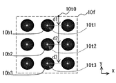
- FIG. 4 is an exemplary image captured by the first observation unit as an example embodying the present invention, and shows an example of an image image observed by the camera 35 of the first imaging unit.
- the image image represents an image image obtained by observing the observation area 10f from the direction orthogonal to the substrate 10 (Y direction) with the camera 35 in the X direction and the Y direction.
- one point 10t1 to 10t3 of the top of the protrusions 10b1 to b3 is picked up as a bright point, and the protrusion has a substantially spherical shape, so the portion 10r1 other than the top of the head 10r1 Up to 10r3 are imaged as dark portions.
- the top of the protrusion is located at the center of the dark image indicating the protrusion. A bright spot indicating is observed.
- the distances from the reference point 10t0 of the points 10t1 to 10t3 observed in the imaging area of the camera 35 are defined as d1 to d3, respectively.
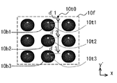
- FIG. 5 is an exemplary image captured by the second observation unit of an example embodying the present invention, and shows an example of an image image observed by the camera 45 of the second imaging unit.
- a direction orthogonal to the second reflected lights 43a and 43b in FIG. 3 is defined as a Y ′ direction
- the observation area 10f is an image image observed in the X direction and the Y ′ direction with the second imaging unit.
- one point 10t of the top of the protrusion 10b is picked up as a bright spot, but since the observation is performed from an oblique direction, the dark part indicating the portion 10r other than the top of the protrusion is in the Y ′ direction. It has an elongated oval shape, and the bright spot indicating one point 10t1 to 10t3 of each top of the head is observed in the dark part image showing the protruding part while being shifted in the Y ′ direction.
- the distances from the reference point 10t0 of the points 10t1 to 10t3 observed in the imaging area of the camera 45 are defined as d'1 to d'3, respectively.
- FIG. 6 is a front view showing an example of a form embodying the present invention, and shows a state in which FIG. 3 is viewed from the side (that is, in the direction of the arrow in the X direction).
- D1 to d3 indicating the position of the bright spot at the top of the protrusions 10b1 to 10b3 imaged by the camera 35 do not change even if the heights of the protrusions 10b1 to 10b3 vary.
- d′ 1 to d′ 3 indicating the positions of the bright spots at the tops of the protrusions 10b1 to 10b3 imaged by the camera 45 are proportional to the variation in height if the height of the protrusions 10b1 to 10b3 varies. Change.
- the heights of the protrusions 10b1 to 10b3 are H1 to H3, their variations are ⁇ h 1 to ⁇ h 3 , and the general expression is that the height of the nth protrusion is H n , and the variations thereof. Is defined as ⁇ h n .
- the height of the nth protrusion is a variation Delta] h n, between the shift amount [Delta] d n which is calculated on the basis of the image observed its top portion,
- the protruding portion 10 of the substrate 10 is appropriately divided into predetermined imaging ranges, and images are simultaneously picked up by two observation units for each of the divided imaging ranges.
- variation in the height of the top part of each protrusion part is computable from each luminescent point information contained in the imaged image.
- the line-shaped third illumination light 52 is irradiated from the third direction toward the surface of the substrate 10, the reflected light is imaged by the third imaging unit, and the protruding portion 10 b using the principle of triangulation.
- the correct position of the substrate 10 is measured, and as described later, the height distribution from the substrate plane of the protrusion is calculated by combining the stereo observation method described above and the light cutting described below.
- FIG. 7 is an exemplary image captured by the third observation unit as an example embodying the present invention, and shows an example of an image image observed by the camera 55 of the third imaging unit.
- a direction perpendicular to the third reflected light 53 is defined as a Y ′′ direction, and the third reflected light 53 in FIG. 1 is imaged.
- the line illumination 51 irradiated from the third illumination unit is irradiated as line-shaped illumination light longer than the diameter of the protrusion, and the light 53a reflected by the top of the protrusion 10b is a point.
- the light 53b reflected by the planar portion of the substrate 10 is imaged as a line shaped light.
- the distance in the Y ′′ direction from the reference point 10 of the light 53a reflected at the top of the head observed in the imaging area of the camera 55 is L1
- the reference point 10 of the light 53b reflected at the flat portion of the substrate 10 is L1.
- FIG. 8 is a front view showing an example of a form embodying the present invention, and shows a state in which FIG. 1 is viewed from the side (that is, in the arrow direction in the X direction).
- the third irradiation light 52 is irradiated toward the substrate 10 from the third direction at a predetermined angle ⁇ 3 with the surface of the substrate 10 and reflected by the top of the protrusion, and the surface of the substrate 10.
- the angle formed by the light 53b reflected from the surface forms a predetermined angle ⁇ 3 with the surface of the substrate 10.
- the reference point RP is defined, and the position where the light 53z reflected from the portion at the angle ⁇ 3 is observed by the camera 55 is defined as Lz.
- Lz the position where the light 53z reflected from the portion at the angle ⁇ 3 is observed by the camera 55.
- H0 can be calculated based on the relational expression.
- the actual height H n of each crown is expressed as a plus component in the directions of arrows in the Z direction, the Y ′ direction, and the Y ′′ direction. From ⁇ h n in Equations 1 and 2 and 0 in Equation 3, the height H n of the top of the n-th protruding portion from the surface of the substrate 10 is
- the calibration tool 10c on which a lattice pattern is formed is prepared, and these patterns are imaged by the cameras 35 and 45.
- the chromium film 10p is a uniform metal film with a known thickness, and the light reflected on the surface is observed in stereo using the cameras 35 and 45.
- the quartz surface of the calibration tool 10 c that is, the bottom of the lattice pattern
- the reflected light from the quartz surface is observed using the line-shaped third illumination light 52 and the camera 55.
- the variation ⁇ h n of the height H n of the nth protrusion calculated by the above stereo observation method is calculated as the variation of the height of the top of the head relative to the height h0 of the reference point PR.
- the shift amount [Delta] d n which is calculated based on the observed image by the stereo observation method, from the calculated deviation amount L2 Metropolitan based on the observed image by the line light triangulation method, the actual protrusion of the head the height H n of the top can be calculated.
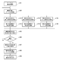
- FIG. 9 is a flowchart showing an operation flow of an example embodying the present invention, in which a large number of protruding portions 10b on the substrate 10 are divided into several areas, and sequential movement and observation are repeated. A series of flows for calculating the height of the protrusion is shown for each step.
- the substrate 10 is placed on the table 23 of the protrusion height measuring device 1 (s101). Subsequently, the table 23 is moved to the observation position (s102), the first illumination light 32 is irradiated from the first direction toward the observation area 10f (s113), and the reflected light is observed by the first imaging unit. (S114). Thereafter, the second illumination light 42 is irradiated from the second direction toward the observation area 10f (s123), and the reflected light is observed by the second imaging unit (s124). Thereafter, the line-shaped third illumination light 52 is irradiated from the third direction toward the observation area 10f (s133), and the reflected light is observed by the third imaging unit (s134).
- the height from the base surface of each protrusion 10b in the observation area 10f is calculated (s105).
- it is determined whether or not all of the observation target areas have been observed (s106). If there is an observation target area to be continuously observed, the table 23 is moved to that place, and the above steps s102, s113 to s134, Repeat 105. If it is determined that all observations have been completed, the results calculated in each observation area are combined and calculated as the heights of all the protrusions 10b in the substrate 10 (s107).
- the table 23 is moved to the substrate delivery position (s108), and the substrate 10 is taken out from the table 23 (s109).
- the first illumination light and the second illumination light are not emitted at the same time if the main wavelengths are the same, but the emission timing is slightly shifted. In this case, if each light emission time is short, measurement can be performed without increasing the time to image one observation area. And since the 1st illumination light and the 2nd illumination light can be made into the same main wavelength, components, such as illumination, a camera, and a filter, can be made shared, and it becomes unnecessary to prepare an exclusive component separately. Therefore, there is an effect that the cost of the apparatus and maintenance can be reduced.
- the present invention can be applied because the bright point due to the other illumination is not detected by shifting the light emission time and the imaging timing.
- the present invention can be applied even if the third illumination light 52 in the form of a line is irradiated outside the observation area 10f, it is preferable to irradiate the observation light in the observation area 10f. If it does so, it can prevent that the 3rd illumination light protrudes from the substrate surface.
- the emission timing may be slightly shifted, and the emission times of the first to third illumination lights and If the imaging time and the time until the next light emission are negligible, it can be said that the above steps s112 to s134 can be performed almost simultaneously.
- the first imaging unit images only the main wavelength of the first illumination light
- the two imaging units are preferably configured to image only the main wavelength of the second illumination light.
- red illumination is used as the first illumination light
- a bandpass filter Fr that transmits only the red wavelength region is used as the first imaging unit
- green illumination is used as the second illumination light
- a band pass filter Fg that transmits only the green wavelength region is used. Then, the green illumination light incident on the first imaging unit is absorbed by the filter Fr, and the red illumination light incident on the second imaging unit is absorbed by the filter Fg.
- the imaging time can be shortened.
- the main wavelength component of the illumination light is changed, or illumination with a common wavelength characteristic (for example, white illumination) is used, but each can be transmitted using a bandpass filter that passes a specific wavelength component.
- the main wavelength component may be changed.
- the line-shaped third illumination light 52 is also preferably made to have a main wavelength component different from that of the first and second illumination lights.
- FIG. 10 is a flowchart showing an operation flow of an example of another embodiment embodying the present invention, in which a large number of protrusions 10b on the substrate 10 are divided into several areas, and successive movement and observation are repeated. A series of different flows for calculating the height of each protrusion is shown step by step.
- steps s113 to s134 are sequentially performed in time series, but instead of this procedure, in another form described here, steps s113 to s134 are simultaneously performed in parallel. The flow to be performed. By doing so, the time required for steps s113 to s134 can be shortened as described above.
- the first direction illumination is performed perpendicularly to the surface of the substrate 10 and the vertically reflected light is observed.
- the first direction only needs to be different from the second direction, as long as the first direction is irradiated toward the surface of the substrate 10 at an angle other than vertical.
- the illumination light irradiated from the first direction may have the same form as the illumination 41.
- the second camera performs shooting from an oblique direction. Therefore, when a normal optical system is used when an area sensor is used, depending on the imaging conditions, only the center of the field of view is in focus, and the field of view may be blurred out of the depth of field. . The blurred part information is wasted because it cannot be used in subsequent processing.
- the optical system may be arranged in a shift optical arrangement or a Scheinproof optical arrangement so as to focus on the entire surface of the captured image and increase the effective image data per unit shooting so as to increase the focal depth.
- the fourth observation unit 6 includes a line illumination 61 as a fourth illumination unit, a lens barrel 64 and a camera 65 as a fourth imaging unit.
- the line illumination 61 can irradiate the linear illumination light 62 with a predetermined length from the fourth direction toward the substrate 10.
- the fourth reflected light 63 emitted from the line illumination 61 and reflected by the plane of the substrate 10 and the top of the protrusion on the substrate 10 passes through the lens barrel 64 and is received by the imaging unit of the camera 65.
- the lens barrel 64 incorporates an optical element such as a lens, and is configured to form an image on the imaging unit of the camera 65 while keeping the plane of the substrate 10 within the depth of focus.
- the light irradiated from the fourth illuminating unit is irradiated and reflected on the substrate 10 at a site different from the light irradiated from the third illuminating unit. Therefore, the inclination of the substrate in the direction orthogonal to the longitudinal direction of the third illumination, which could not be captured only by the third line illumination, can be captured accurately by additionally measuring the fourth line illumination. become.
Landscapes
- Physics & Mathematics (AREA)
- General Physics & Mathematics (AREA)
- Length Measuring Devices By Optical Means (AREA)
Abstract
基板平面上に複数分布している突出部について、頭頂部の相対的な高さのばらつきだけでなく、それぞれ頭頂部の高さを、短時間でかつ高精度に測定できる装置及び方法を提供する。 具体的には、基板平面上に複数分布する突出部の高さを測定する突出部高さ測定装置において、 基板平面に向けて第1及び第2の方向から照明光を照射する第1及び第2照明部と、反射された第1及び第2反射光を撮像する第1及び第2撮像部とを備え、 第1及び第2撮像部で撮像された反射光の位置情報とに基づいて、 突出部の頭頂部同士の相対高さを算出する相対高さ演算部を備え、 第3の方向から突出部の径よりも長いライン状の照明光を照射する第3照明部と、反射された第3反射光を撮像する第3撮像部とを備え、 第3撮像部で撮像された反射光の位置情報と、 相対高さ演算部で算出された結果に基づいて、突出部高さ演算部を備えたことを特徴とする、突出部高さ測定装置及び方法。
Description
本発明は、基板平面上に複数分布している突出部の前記平面から突出した高さ、特にBGAを備える半導体装置上に形成されたバンプ高さなど、を測定する突出部高さ測定装置及び方法に関する。
昨今のエレクトロニクス機器、特に携帯用電子機器などは、小型化と高性能化に伴い、内部に搭載される電子部品がますます高密度で実装されるようになっている。この中でICのパッケージも小型化してきており、BGA(Ball Grid Array)やCSP(Chip Size Package)のように、バンプ接合タイプのパッケージが急速に普及している。さらにはCoC(Chip on a Chip)のようにバンプを搭載したチップを上下に積み重ねて実装する手法も登場している。
このようなバンプ接合タイプのパッケージの場合、パッケージ裏面の端子上にはんだボールを載せてバンプを形成し、パッケージ裏面を実装対象基板に対接させて、バンプ(ボール状のはんだ)をリフローなどにより加熱し、実装対象基板上の配線ランド部に対してはんだ接合をさせることで、実装を行っている。
バンプは、パッケージ上に多数形成されているが、バンプ形成時のプロセスマージンが小さく、均一な高さのバンプを形成するのが難しい。そのため、個々に高さの異なるバンプが形成されてしまう場合がある。このような状況下では、一部のバンプに対して抜き取りで高さ測定し、他のバンプの高さを推定すると、不適切なケースが生じる。その様な不適切さを解消するために、全バンプの高さを測定することが求められている。また、バンプの密集化からチップおよびウェーハあたりのバンプ数は増加しているが、ウェーハに掛けられるバンプ測定のための処理時間はできるだけ短時間である事が求められる。このため、より短時間で全バンプの高さを測定する事が求められている。
また、全バンプはそれぞれの頭頂部の相対的な高さの平坦度(コプラナリティー)が重要ではあるが、それだけではなく、パッケージのベース面からの高さの測定も要求される。それは、小径かつ密集したバンプを使用したチップの実装においては、実装時のチップと基板との隙間量(ギャップ量)に対して、バンプ高さのばらつきに対する許容幅が小さいためである。
もし、全バンプはそれぞれの頭頂部の相対的な高さが揃っていても、バンプ高さが均一でない場合(つまり、全バンプの頭頂部で形成する面と、パッケージのベース面とが平行でない場合)や、平行であるが所望の距離とは異なる場合には、実装不良が生じやすくなる。これは、はんだボールの大きさが予め規定した大きさと異なるため、大きなバンプの場合、バンプが潰れすぎて横に広がることで隣り合うバンプ同士は短絡しやすく、小さなバンプの場合、接合させたいバンプと電極との間にはんだが行き渡らず接合不良となりやすく、所望の導通が得られないといった現象が生じるためである。
これらの「バンプ高さが低い不良バンプの場合は、接合させたいバンプと電極との間が接合不良となり導通が得られない」および「バンプ高さが高い不良バンプの場合は、近接した潰れたバンプ同士が接触してしまい短絡となる」現象はバンプ高さの平坦度(コプラナリティー)の測定では発見する事ができない。
これらの「バンプ高さが低い不良バンプの場合は、接合させたいバンプと電極との間が接合不良となり導通が得られない」および「バンプ高さが高い不良バンプの場合は、近接した潰れたバンプ同士が接触してしまい短絡となる」現象はバンプ高さの平坦度(コプラナリティー)の測定では発見する事ができない。
したがって、小径かつ密集したバンプを使用したチップの実装前にはベース面からのバンプの高さを管理する事が必要であり、逆にベース面からの高さの測定しておけば、プロセス上規定された隙間量(ギャップ量)で実装ができるかどうかを実装前に判定可能であり、高さ不良のバンプのあるチップを実装前に廃棄したり、リワークしたりするなどの対策を行う事ができる。そして、従来の技術としては、基板平面上に複数分布している突出部の高さを測定するために、オートフォーカス法、ステレオカメラ法、光切断法などの技術が開示されている。
1)オートフォーカス法
オートフォーカス法は、オートフォーカスの原理によりバンプに焦点を合わせることを通じてバンプの高さを計測するものである。焦点合わせおよびバンプ高さ計測はバンプの1つずつに対して順次的に行うようになっている。すなわち、測定対象であるバンプのあるチップやウェーハをXYテーブルに搭載し、XYテーブルを微小量移動させてパッケージ上の1つのバンプを光学系の光軸の直下に位置させ、焦点合わせを行い、バンプ高さを計測するといった一連の動作をバンプごとに繰り返し実行するのである(例えば、特許文献1)。
オートフォーカス法は、オートフォーカスの原理によりバンプに焦点を合わせることを通じてバンプの高さを計測するものである。焦点合わせおよびバンプ高さ計測はバンプの1つずつに対して順次的に行うようになっている。すなわち、測定対象であるバンプのあるチップやウェーハをXYテーブルに搭載し、XYテーブルを微小量移動させてパッケージ上の1つのバンプを光学系の光軸の直下に位置させ、焦点合わせを行い、バンプ高さを計測するといった一連の動作をバンプごとに繰り返し実行するのである(例えば、特許文献1)。
しかし、この方法では、バンプ数が増えるにつれて計測時間が増えてしまう。例えばCSPパッケージの1種であるWLP(Wefer Level Package)のICバンプは直径300mmのウェーハ上には200万個以上ある場合があるが、この測定においてXYテーブルの1回の移動には0.2秒、1回の焦点合わせには1秒掛かるとすると、1枚のウェーハ上の全バンプの測定には462時間以上掛かることとなる。この測定時間は実際の生産現場においては現実的ではない。
2)ステレオカメラ法
ステレオカメラ法では、バンプに光を照射し、バンプ頭頂部からの反射光を複数のカメラで撮影してその位置をそれぞれ抽出し、それらの座標位置の差からバンプ頭頂部の座標を求めている。このステレカメラオ法では、CCDやCMOSなどの2次元カメラ(撮像部)を用いれば、所定範囲に存在する複数のバンプを一度に撮像して、それぞれの高さを求めることができる(例えば、特許文献2~5)。
ステレオカメラ法では、バンプに光を照射し、バンプ頭頂部からの反射光を複数のカメラで撮影してその位置をそれぞれ抽出し、それらの座標位置の差からバンプ頭頂部の座標を求めている。このステレカメラオ法では、CCDやCMOSなどの2次元カメラ(撮像部)を用いれば、所定範囲に存在する複数のバンプを一度に撮像して、それぞれの高さを求めることができる(例えば、特許文献2~5)。
一方、測定分解能と測定レンジとの間にはトレードオフの関係があり、測定分解能を高めようとすると、測定レンジが狭くなる。そのため、バンプ頭頂部を測定レンジ内に納め、それぞれのバンプの頭頂部の高さのばらつきが測定できたとしても、基板平面上からバンプ頭頂部までの高さが分からない。また、測定対象のバンプが多数あり、一度に撮像ができない場合、複数のエリアに分割して測定する必要があるが、ステレオカメラ法では撮像エリア内のこのバンプの相対的な高さの差しか求めることができず、先に撮像したバンプ高さとの対比ができない。どうしても対比させたい場合は、先に撮像したバンプが次に撮像する視野の内に含まれるようにして、撮像を行う必要があった。
しかし、これでは重複して撮像する必要があり、短時間で撮像を終えることができない。さらに、先の情報を引き継いで高さを求めることになるため、先の測定で得られた高さ情報に基づき、次の高さ計測の情報としていくということは、ひとたび誤差が含まれると、誤差の連鎖が生じてしまい、最終的に精度の高い結果を得られない恐れもある。
3)光切断法
光切断法は、測定対象に対して斜め(例えば測定対象の垂直方向を0°とした時に45°)の角度でレーザースリット光投射デバイスによってレーザースリット光を投影し、被検査部に生じたレーザースリット光による反射光をCCDカメラなどの撮像部によって撮像する方法である(特許文献6)。測定対象上に生じた光切断線は、測定対象の高さに応じて位置が水平方向に変位するという特性を有している。従って、撮像画像内の光切断線の変位に基づいて測定対象のレーザースリットを投射したラインの高さ分布を算出することができ、測定対象を少しずつ動かしながらラインの高さ分布を繰り返し測定することで、測定対象の面内の高さ分布を得る事ができる。
光切断法は、測定対象に対して斜め(例えば測定対象の垂直方向を0°とした時に45°)の角度でレーザースリット光投射デバイスによってレーザースリット光を投影し、被検査部に生じたレーザースリット光による反射光をCCDカメラなどの撮像部によって撮像する方法である(特許文献6)。測定対象上に生じた光切断線は、測定対象の高さに応じて位置が水平方向に変位するという特性を有している。従って、撮像画像内の光切断線の変位に基づいて測定対象のレーザースリットを投射したラインの高さ分布を算出することができ、測定対象を少しずつ動かしながらラインの高さ分布を繰り返し測定することで、測定対象の面内の高さ分布を得る事ができる。
しかし、光切断法では測定対象を少しずつ動かしながらラインの高さ分布を繰り返し測定するために、測定時間が掛かるという問題がある。また、近年バンプは小径化が進んでいるが、小径バンプのような平坦面上の小径突起物を測定しようとするとバンプ頭頂部と平坦面の反射光が大きく異なることから、光切断線の撮像明るさが大きく異なり、この結果バンプ頭頂部と平坦面の少なくともいずれかの光切断線の位置を正しく検出できず、バンプ高さを正しく測定できないという問題がある。
上述したように、従来の技術には一長一短があり、基板平面上に複数分布している突出部について、頭頂部の相対的な高さのばらつきだけでなく、基板平面から突出したそれぞれ頭頂部の高さを、短時間でかつ高精度に測定することが困難であった。
そこで本発明は、基板平面上に複数分布している突出部について、頭頂部の相対的な高さのばらつきだけでなく、基板平面から突出したそれぞれ頭頂部の高さを、短時間でかつ高精度に測定できる装置及び方法を提供すること目的としている。
以上の課題を解決するために、請求項1に記載の発明は、
基板平面上に複数分布している突出部の前記基板平面から突出した高さを測定する突出部高さ測定装置において、
測定対象となる前記突出部を含む前記基板平面に向けて第1の方向から照明光を照射する第1照明部と、
前記第1照明部から照射されて前記突出部の頭頂部で反射された第1反射光を撮像する第1撮像部と、
測定対象となる前記突出部を含む前記基板平面に向けて第2の方向から照明光を照射する第2照明部と、
前記第2照明部から照射されて前記突出部の頭頂部で反射された第2反射光を撮像する第2撮像部とを備え、
前記第1撮像部で撮像された前記突出部の頭頂部からの反射光の位置情報と、
前記第2撮像部で撮像された前記突出部の頭頂部からの反射光の位置情報とに基づいて、前記突出部の頭頂部同士の相対高さを算出する相対高さ演算部を備え、
第3の方向から前記基板平面に向けて前記突出部の径よりも長いライン状の照明光を照射する第3照明部と、
前記第3照明部から照射されて前記基板平面上で反射された第3反射光を撮像する第3撮像部とを備え、
前記第3撮像部で撮像された前記基板平面上からの反射光の位置情報と、
前記相対高さ演算部で算出された結果に基づいて、
前記基板平面上に複数分布している各々の突出部の前記基板平面から突出した高さを算出する突出部高さ演算部を備えたことを特徴とする、突出部高さ測定装置である。
基板平面上に複数分布している突出部の前記基板平面から突出した高さを測定する突出部高さ測定装置において、
測定対象となる前記突出部を含む前記基板平面に向けて第1の方向から照明光を照射する第1照明部と、
前記第1照明部から照射されて前記突出部の頭頂部で反射された第1反射光を撮像する第1撮像部と、
測定対象となる前記突出部を含む前記基板平面に向けて第2の方向から照明光を照射する第2照明部と、
前記第2照明部から照射されて前記突出部の頭頂部で反射された第2反射光を撮像する第2撮像部とを備え、
前記第1撮像部で撮像された前記突出部の頭頂部からの反射光の位置情報と、
前記第2撮像部で撮像された前記突出部の頭頂部からの反射光の位置情報とに基づいて、前記突出部の頭頂部同士の相対高さを算出する相対高さ演算部を備え、
第3の方向から前記基板平面に向けて前記突出部の径よりも長いライン状の照明光を照射する第3照明部と、
前記第3照明部から照射されて前記基板平面上で反射された第3反射光を撮像する第3撮像部とを備え、
前記第3撮像部で撮像された前記基板平面上からの反射光の位置情報と、
前記相対高さ演算部で算出された結果に基づいて、
前記基板平面上に複数分布している各々の突出部の前記基板平面から突出した高さを算出する突出部高さ演算部を備えたことを特徴とする、突出部高さ測定装置である。
以上の課題を解決するために、請求項5に記載の発明は、
基板平面上に複数分布している突出部の前記基板平面から突出した高さを測定する突出部高さ測定方法において、
前記基板平面に向けて第1の方向から第1の照明光を照射する第1照明照射ステップと、
前記第1照明照射ステップで照射された光が前記突出部の頭頂部で反射された第1反射光を撮像する第1撮像ステップと、
前記基板平面に向けて第2の方向から照明光を照射する第2照明照射ステップと、
前記第2照明照射ステップで照射された光が前記突出部の頭頂部で反射された第2反射光を撮像する第2撮像ステップとを有し、
前記第1撮像ステップで撮像された前記突出部の頭頂部からの反射光の位置情報と、
前記第2撮像ステップで撮像された前記突出部の頭頂部からの反射光の位置情報とに基づいて、
前記突出部の頭頂部同士の相対高さを算出する相対高さ演算ステップを有し、
第3の方向から前記基板平面に向けて前記突出部の径よりも長いライン状の照明光を照射する第3照明照射ステップと、
前記第3照明照射ステップで照射された光が前記基板平面上で反射された第3反射光を撮像する第3撮像ステップとを有し、
前記第3撮像ステップで撮像された前記基板平面上からの反射光の位置情報と、
前記相対高さ演算ステップで算出された結果に基づいて、
前記基板平面上に複数分布している各々の突出部の前記基板平面から突出した高さを算出する突出部高さ演算ステップを有することを特徴とする、突出部高さ測定方法である。
基板平面上に複数分布している突出部の前記基板平面から突出した高さを測定する突出部高さ測定方法において、
前記基板平面に向けて第1の方向から第1の照明光を照射する第1照明照射ステップと、
前記第1照明照射ステップで照射された光が前記突出部の頭頂部で反射された第1反射光を撮像する第1撮像ステップと、
前記基板平面に向けて第2の方向から照明光を照射する第2照明照射ステップと、
前記第2照明照射ステップで照射された光が前記突出部の頭頂部で反射された第2反射光を撮像する第2撮像ステップとを有し、
前記第1撮像ステップで撮像された前記突出部の頭頂部からの反射光の位置情報と、
前記第2撮像ステップで撮像された前記突出部の頭頂部からの反射光の位置情報とに基づいて、
前記突出部の頭頂部同士の相対高さを算出する相対高さ演算ステップを有し、
第3の方向から前記基板平面に向けて前記突出部の径よりも長いライン状の照明光を照射する第3照明照射ステップと、
前記第3照明照射ステップで照射された光が前記基板平面上で反射された第3反射光を撮像する第3撮像ステップとを有し、
前記第3撮像ステップで撮像された前記基板平面上からの反射光の位置情報と、
前記相対高さ演算ステップで算出された結果に基づいて、
前記基板平面上に複数分布している各々の突出部の前記基板平面から突出した高さを算出する突出部高さ演算ステップを有することを特徴とする、突出部高さ測定方法である。
上記の突出部高さ測定装置及び方法を用いるので、
所定の撮像エリアについて、撮像タイミングを僅かにずらすだけでほぼ同時に撮影を行って、基板平面上に複数分布している突出部について、基板平面から突出したそれぞれ頭頂部の高さを高精度に算出することができる。また、測定対象を複数の撮像エリアに分割した場合でも、分割した撮像エリア毎にそれぞれ、ほぼ同時に撮影を行うことができる。
所定の撮像エリアについて、撮像タイミングを僅かにずらすだけでほぼ同時に撮影を行って、基板平面上に複数分布している突出部について、基板平面から突出したそれぞれ頭頂部の高さを高精度に算出することができる。また、測定対象を複数の撮像エリアに分割した場合でも、分割した撮像エリア毎にそれぞれ、ほぼ同時に撮影を行うことができる。
請求項2に記載の発明は、
前記第1照明部から照射される光の照射と、
前記第2照明部から照射される光の照射とが、時間をずらして行われる
ことを特徴とする、請求項1に記載の突出部高さ測定装置である。
前記第1照明部から照射される光の照射と、
前記第2照明部から照射される光の照射とが、時間をずらして行われる
ことを特徴とする、請求項1に記載の突出部高さ測定装置である。
請求項6に記載の発明は、
前記第1照明照射ステップと、前記第2照明照射ステップとを、
時間をずらして行うことを特徴とする、請求項5に記載の突出部高さ測定方法である。
前記第1照明照射ステップと、前記第2照明照射ステップとを、
時間をずらして行うことを特徴とする、請求項5に記載の突出部高さ測定方法である。
上記の突出部高さ測定装置及び方法を用いれば、
第1及び第2の観察部に用いる照明の主波長が同じであっても、照射のタイミングをずらすだけでそれぞれの画像を撮像することができ、他方の照明から照射される主波長成分を撮像することがなく、測定精度には影響を及ぼすことがない。
第1及び第2の観察部に用いる照明の主波長が同じであっても、照射のタイミングをずらすだけでそれぞれの画像を撮像することができ、他方の照明から照射される主波長成分を撮像することがなく、測定精度には影響を及ぼすことがない。
請求項3に記載の発明は、
前記第1照明部から照射される光の主波長が、
前記第2照明部から照射される光の主波長とは異なっており、
前記第1撮像部と前記第2撮像部とは同時に撮像を行う
ことを特徴とする、請求項1に記載の突出部高さ測定装置である。
前記第1照明部から照射される光の主波長が、
前記第2照明部から照射される光の主波長とは異なっており、
前記第1撮像部と前記第2撮像部とは同時に撮像を行う
ことを特徴とする、請求項1に記載の突出部高さ測定装置である。
請求項7に記載の発明は、
前記第1照明照射ステップで照射される光の主波長が、
前記第2照明照射ステップで照射される光の主波長とは異なっており、
前記第1撮像ステップと前記第2撮像ステップとを同時に行う
ことを特徴とする、請求項5に記載の突出部高さ測定方法である。
前記第1照明照射ステップで照射される光の主波長が、
前記第2照明照射ステップで照射される光の主波長とは異なっており、
前記第1撮像ステップと前記第2撮像ステップとを同時に行う
ことを特徴とする、請求項5に記載の突出部高さ測定方法である。
上記の突出部高さ測定装置及び方法を用いれば、
第1及び第2の照明光の照射タイミングをずらすことなく、同時に照射しても、それぞれの撮像部で観察する画像の中に、他の撮像部で用いる波長の光は撮像されない。そのため、第1及び第2の観察部で突出部を撮像するために要する時間を短縮することができ、測定精度には影響を及ぼさない。
第1及び第2の照明光の照射タイミングをずらすことなく、同時に照射しても、それぞれの撮像部で観察する画像の中に、他の撮像部で用いる波長の光は撮像されない。そのため、第1及び第2の観察部で突出部を撮像するために要する時間を短縮することができ、測定精度には影響を及ぼさない。
請求項4に記載の発明は、
前記第3照明部から照射される光の主波長が、
前記第1照明部及び/又は前記第2照明部から照射される光の主波長とは異なっており、前記第3撮像部と、前記第3撮像部とは異なる主波長の光を撮像する前記第1撮像部及び/又は前記第2撮像部とを、同時に撮像を行う
ことを特徴とする、請求項1~3のいずれかに記載の突出部高さ測定装置である。
前記第3照明部から照射される光の主波長が、
前記第1照明部及び/又は前記第2照明部から照射される光の主波長とは異なっており、前記第3撮像部と、前記第3撮像部とは異なる主波長の光を撮像する前記第1撮像部及び/又は前記第2撮像部とを、同時に撮像を行う
ことを特徴とする、請求項1~3のいずれかに記載の突出部高さ測定装置である。
請求項8に記載の発明は、
前記第3照明照射ステップで照射される光の主波長が、
前記第1照明照射ステップ及び/又は前記第2照明照射ステップから照射される光の主波長とは異なっており、
前記第3撮像ステップを、前記第3撮像ステップとは異なる主波長の光を撮像する前記第1撮像ステップ及び/又は前記第2撮像ステップと同時に撮像を行う
ことを特徴とする、請求項5~7に記載の突出部高さ測定方法である。
前記第3照明照射ステップで照射される光の主波長が、
前記第1照明照射ステップ及び/又は前記第2照明照射ステップから照射される光の主波長とは異なっており、
前記第3撮像ステップを、前記第3撮像ステップとは異なる主波長の光を撮像する前記第1撮像ステップ及び/又は前記第2撮像ステップと同時に撮像を行う
ことを特徴とする、請求項5~7に記載の突出部高さ測定方法である。
上記の突出部高さ測定装置及び方法を用いれば、
第1から第3の照明を、それぞれ同時に照射して撮像でき、第1及び第2撮像部で観察するエリア内に第3の照明を照射しても、それぞれの撮像部で観察する画像の中に、他の撮像部で用いる波長の光は撮像されない。そのため、照明光の照射タイミングをずらす必要がなくなるので、前記突起物の高さ測定を行うための時間を極めて短くすることができる。また、第1及び第2撮像部で撮像する部分の平面部の高さを測定できるため、基板周辺部であっても、第3の照明光が基板表面からはみ出してしまうことを防ぐことができる。
第1から第3の照明を、それぞれ同時に照射して撮像でき、第1及び第2撮像部で観察するエリア内に第3の照明を照射しても、それぞれの撮像部で観察する画像の中に、他の撮像部で用いる波長の光は撮像されない。そのため、照明光の照射タイミングをずらす必要がなくなるので、前記突起物の高さ測定を行うための時間を極めて短くすることができる。また、第1及び第2撮像部で撮像する部分の平面部の高さを測定できるため、基板周辺部であっても、第3の照明光が基板表面からはみ出してしまうことを防ぐことができる。
基板平面上に複数分布している突出部について、頭頂部の相対的な高さのばらつきだけでなく、基板平面から突出したそれぞれ頭頂部の高さを、短時間でかつ高精度に測定できる。そのため、本発明をはんだバンプの測定に適用すれば、はんだ不良(隣接電極同士のショートや、導通不良)の発生を未然に防ぐことができる。
本発明を実施するための形態について、図を用いながら説明する。
図1は、本発明を具現化する形態の一例を示す斜視図である。
各図において直交座標系の3軸をX、Y、Zとし、XY平面を水平面、Z方向を鉛直方向とする。特にZ方向は矢印の方向を上とし、その逆方向を下と表現する。
本発明を具現化する突出部高さ測定装置1は、基板移動部2と、第1の観察部3と、第2の観察部4と、第3の観察部5とを含んで構成されている。
図1は、本発明を具現化する形態の一例を示す斜視図である。
各図において直交座標系の3軸をX、Y、Zとし、XY平面を水平面、Z方向を鉛直方向とする。特にZ方向は矢印の方向を上とし、その逆方向を下と表現する。
本発明を具現化する突出部高さ測定装置1は、基板移動部2と、第1の観察部3と、第2の観察部4と、第3の観察部5とを含んで構成されている。
[基板移動部]
基板移動部2は、突出部高さ測定装置1の装置ベース(図示せず)上に載置されたY軸ステージ21と、Y軸ステージ21上に取り付けられたX軸ステージ22と、X軸ステージ22上に取り付けられたテーブル23とが含まれて構成されている。
Y軸ステージ21は、その上に取り付けられたX軸ステージ22をY方向に所定の速度で移動させ、所定の位置に位置決め移動させ、静止させることができる。
X軸ステージ22は、その上に取り付けられたテーブル23をX方向に所定の速度で移動させ、所定の位置に位置決め移動させることができる。
テーブル23は、表面に溝や孔が形成されており、前記溝や孔は、開閉制御用バルブを介して真空源に接続されている。テーブル23上には、測定対象となる基板10を載置することができる。
基板移動部2は、突出部高さ測定装置1の装置ベース(図示せず)上に載置されたY軸ステージ21と、Y軸ステージ21上に取り付けられたX軸ステージ22と、X軸ステージ22上に取り付けられたテーブル23とが含まれて構成されている。
Y軸ステージ21は、その上に取り付けられたX軸ステージ22をY方向に所定の速度で移動させ、所定の位置に位置決め移動させ、静止させることができる。
X軸ステージ22は、その上に取り付けられたテーブル23をX方向に所定の速度で移動させ、所定の位置に位置決め移動させることができる。
テーブル23は、表面に溝や孔が形成されており、前記溝や孔は、開閉制御用バルブを介して真空源に接続されている。テーブル23上には、測定対象となる基板10を載置することができる。
基板移動部2は、上述の様な構成をしているので、テーブル23上に載置された基板10を、XY方向に所定の速度で移動させ、所定の位置に位置決め移動させ、静止させることができる。
[基板観察部]
第1の観察部3は、第1照明部としての同軸落射照明31と、第1撮像部としての鏡筒34とカメラ35とが含まれて構成されている。同軸落斜照明31は、基板10に向けて第1の方向から照射された第1の照明光32を照射することができる。同軸落斜照明31から照射され、基板10の平面及び基板10上の突出部の頭頂部で反射された第1反射光33は、鏡筒34を通りカメラ35の撮像部に受光される。鏡筒34は、レンズなどの光学素子が組み込まれており、基板10上の突出部の頭頂部を焦点深度内に収めてカメラ35の撮像部に結像させるように構成されている。
第1の観察部3は、第1照明部としての同軸落射照明31と、第1撮像部としての鏡筒34とカメラ35とが含まれて構成されている。同軸落斜照明31は、基板10に向けて第1の方向から照射された第1の照明光32を照射することができる。同軸落斜照明31から照射され、基板10の平面及び基板10上の突出部の頭頂部で反射された第1反射光33は、鏡筒34を通りカメラ35の撮像部に受光される。鏡筒34は、レンズなどの光学素子が組み込まれており、基板10上の突出部の頭頂部を焦点深度内に収めてカメラ35の撮像部に結像させるように構成されている。
第2の観察部4は、第2照明部としての照明41と、第2撮像部としての鏡筒44とカメラ45とが含まれて構成されている。照明41は、基板10に向けて第2の方向から照射された第2の照明光42を照射することができる。照明41から照射され、基板10の平面及び基板10上の突出部の頭頂部で反射された第2反射光43は、鏡筒44を通りカメラ45の撮像部に受光される。鏡筒44は、レンズなどの光学素子が組み込まれており、基板10上の突出部の頭頂部を焦点深度内に収めてカメラ45の撮像部に結像させるように構成されている。
第3の観察部5は、第3照明部としてのライン照明51と、第3撮像部としての鏡筒54とカメラ55とが含まれて構成されている。ライン照明51は、基板10に向けて第3の方向から所定の長さで線状の、第3の照明光52を照射することができる。ライン照明51として照射され、基板10の平面及び基板10上の突出部の頭頂部で反射された第3反射光53は、鏡筒54を通りカメラ55の撮像部に受光される。鏡筒54は、レンズなどの光学素子が組み込まれており、基板10の平面を焦点深度内に収めてカメラ55の撮像部に結像させるように構成されている。
カメラ35と、照明41と、カメラ45と、ライン照明51と、カメラ55は、突出部高さ測定装置1の前記装置ベースに取り付けられた、フレーム(図示せず)に取り付けられている。
上述の同軸落斜照明31としては、鏡筒34に取り付けて用いられ、鏡筒内部のハーフミラーで反射された光がカメラ35で撮像される範囲を含む範囲に光が照射される形態のものが例示できる。
上述の照明41としては、点光源、線発光若しくは面発光の光源とミラー又はレンズを組み合わせた形態のものが例示でき、カメラ45で撮像される範囲を含む範囲に光が照射されるものであれば良い。
上述のライン照明51としては、線発光、点光源若しくは面発光の光源を用い、照射された光をライン状に成形したものや、レーザ若しくはレーザダイオードから発せられたビームをシリンドリカルレンズを通過させたり、シリンドリカルミラーで反射させたりして、1方向に引き延ばし、ライン状に成形したものが例示できる。
上述のカメラ35,45,55としては、イメージエリアセンサと呼ばれる、CCDやCMOSに代表される、撮像素子が2次元的に配列された形態のものが例示でき、撮像した画像の明るさに応じた画像信号を外部へ出力することができる。
上述の同軸落斜照明31としては、鏡筒34に取り付けて用いられ、鏡筒内部のハーフミラーで反射された光がカメラ35で撮像される範囲を含む範囲に光が照射される形態のものが例示できる。
上述の照明41としては、点光源、線発光若しくは面発光の光源とミラー又はレンズを組み合わせた形態のものが例示でき、カメラ45で撮像される範囲を含む範囲に光が照射されるものであれば良い。
上述のライン照明51としては、線発光、点光源若しくは面発光の光源を用い、照射された光をライン状に成形したものや、レーザ若しくはレーザダイオードから発せられたビームをシリンドリカルレンズを通過させたり、シリンドリカルミラーで反射させたりして、1方向に引き延ばし、ライン状に成形したものが例示できる。
上述のカメラ35,45,55としては、イメージエリアセンサと呼ばれる、CCDやCMOSに代表される、撮像素子が2次元的に配列された形態のものが例示でき、撮像した画像の明るさに応じた画像信号を外部へ出力することができる。
図2は、本発明を具現化する形態の一例を示すシステム構成図である。図2に示すように、本発明を具現化する突出部高さ測定装置1は、上述した基板移動部2、第1の観察部3、第2の観察部4及び第3の観察部5の各機器が、制御部9の各機器と接続されている。
制御部9には、制御用コンピュータ90と、情報入力部91と、情報出力部92と、発報部93と、情報記録部94と、機器制御ユニット95と、画像処理ユニット96とが接続されて含まれている。
制御用コンピュータ90としては、マイコン、パソコン、ワークステーションなどの、数値演算ユニットが搭載されたものが例示される。
情報入力部91としては、キーボードやマウスやスイッチなどが例示される。
情報出力部92としては、画像表示ディスプレイやランプなどが例示される。
情報入力部91としては、キーボードやマウスやスイッチなどが例示される。
情報出力部92としては、画像表示ディスプレイやランプなどが例示される。
発報部93としては、ブザーやスピーカ、ランプなど、作業者に注意喚起をすることができるものが例示される。
情報記録部94としては、メモリーカードやデータディスクなどの、半導体記録媒体や磁気記録媒体や光磁気記録媒体などが例示される。
機器制御ユニット95としては、プログラマブルコントローラやモーションコントローラと呼ばれる機器などが例示される。
情報記録部94としては、メモリーカードやデータディスクなどの、半導体記録媒体や磁気記録媒体や光磁気記録媒体などが例示される。
機器制御ユニット95としては、プログラマブルコントローラやモーションコントローラと呼ばれる機器などが例示される。
制御用コンピュータ90には、画像処理ユニット96を介して、カメラ35,45,55から出力された画像信号が入力される。画像処理ユニット96は、一般にフレームグラバー(FrameGrabber)などと呼ばれる画像信号をデジタイズするデバイスが搭載されており、カメラ35,45,55から出力された画像信号を取り込み、それぞれのカメラで撮像した視野内の明るさ情報に基づいて、予め設定した基準値を超える明るさの観察点を輝点として捉え、突出部の頭頂部を検出することができる。さらに、観察視野に相当する実際の観察面の寸法をキャリブレーションしておけば、前記輝点が視野内のどの位置にあるかを演算処理し、基板上の輝点の位置を実寸に換算して算出することもできる。
画像処理ユニット96としては、制御用コンピュータ90の外部に設置される形態のもの、制御用コンピュータ90の筐体内に接続される形態のもの、制御用コンピュータ90の画像処理部を利用した形態のものなどが例示できる。
そして、後述で詳細説明をするように、画像処理ユニット96又は制御用コンピュータ90は、予め設定した基準値を超える明るさの観察点を輝点として捉え、基板平面上に複数分布している突出部の前記基板平面から突出した高さを測定に用いることができ、突出部の頭頂部同士の相対高さを算出する相対高さ演算部を構成する。
機器制御ユニット95には、Y軸ステージ21、X軸ステージ22が接続されている。
基板10上の任意の領域に対し、カメラ35,45で画像を取得できるように、テーブル23を移動させ、静止させて、画像を取得する。或いは、テーブル23を所定の速度で動かしながら、照明にキセノンランプやハロゲンランプを用いて大光量の光を瞬間的に発光させたり、高速シャッター機能を有するカメラを用いたりして、静止しているとみなす画像を取得するようにしても良い。
基板10上の任意の領域に対し、カメラ35,45で画像を取得できるように、テーブル23を移動させ、静止させて、画像を取得する。或いは、テーブル23を所定の速度で動かしながら、照明にキセノンランプやハロゲンランプを用いて大光量の光を瞬間的に発光させたり、高速シャッター機能を有するカメラを用いたりして、静止しているとみなす画像を取得するようにしても良い。
また、機器制御ユニット95には、同軸落斜照明31、照明41及びライン照明51の光量をそれぞれ個別に調節するための光量調節ユニット30,40,50が接続されている。光量調節ユニット30,40,50における照明の光量調節の方式としては、印可する電圧や電流を調節したり、電圧や電流の印可時間を調節したりする方式を例示できる。
機器制御ユニット95は、その他の制御機器(図示せず)と接続されており、それらに対して制御用信号を与えることにより、各機器を動作させたり静止させたりすることができるようになっている。
[ステレオ観察]
突出部10bの頭頂部のそれぞれの高さのばらつきの測定は、2つのカメラ35,45を用い、ステレオ観察法と呼ばれる手法に基づいて行う。
図3は、本発明を具現化する形態の一例を示す部分拡大斜視図であり、図1を部分拡大して示している。第1の方向から照射された第1の照明光32と、第2の方向から照射された第2の照明光42とは、カメラ35及びカメラ45が互いに共通して観察する、基板10の観察エリア10fに向けて照射される。
突出部10bの頭頂部のそれぞれの高さのばらつきの測定は、2つのカメラ35,45を用い、ステレオ観察法と呼ばれる手法に基づいて行う。
図3は、本発明を具現化する形態の一例を示す部分拡大斜視図であり、図1を部分拡大して示している。第1の方向から照射された第1の照明光32と、第2の方向から照射された第2の照明光42とは、カメラ35及びカメラ45が互いに共通して観察する、基板10の観察エリア10fに向けて照射される。
図3では、説明の簡単化のために、観察エリア10f内に突出部10bが9つ含まれている様子が示されている。そのうち3つの突出部10b1~10b3に着目し、前記照明光32,42のうち、突出部10b1~10b3のそれぞれの頭頂部の一点10t1~10t3に照射されて反射する光33a1~33a3及び43a1~43a3について説明を行う。
突出部10b1~10b3のそれぞれの頭頂部の一点10t1~10t3に向けて、第1の照明光32a1~32a3と、第2の照明光42a1~42a3が、それぞれ照射されている。さらに、突出部10b1~10b3のそれぞれの頭頂部の一点10t1~10t3で反射された光は、それぞれ第1反射光33a1~33a3と、第2反射光43a1~43a3として、カメラ35,45で撮像される。
このとき、第1の照明光32a1~32a3と、第1反射光33a1~33a3とは、突出部の頭頂部で反射される光なので、正反射の関係にある。同様に、第2の照明光42a1~42a3と、第2反射光43a1~43a3も、正反射の関係にある。
図4は、本発明を具現化する形態の一例の第1の観察部で撮像された例示画像であり、第1撮像部のカメラ35で観察した画像イメージの例を示している。前記画像イメージは、基板10に直交する方向(Y方向)から観察エリア10fを、カメラ35でX方向及びY方向を観察した画像イメージを表している。
第1撮像部で観察した画像においては、突出部10b1~b3の頭頂部の一点10t1~10t3が輝点として撮像されており、突出部はほぼ球状をしているので、頭頂部以外の部分10r1~10r3が暗部として撮像されている。また、第1照射光32a1~32a3と第1反射光33a1~33a3とが、ともに基板表面に対して垂直の角度をなしているので、突出部を示す暗部画像の中央に、突出部の頭頂部を示す輝点が観察されることになる。このとき、カメラ35の撮像エリア内で観察された、前記点10t1~10t3の基準点10t0から距離を、それぞれd1~d3と定義する。
図5は、本発明を具現化する形態の一例の第2の観察部で撮像された例示画像であり、第2撮像部のカメラ45で観察した画像イメージの例を示している。図3における第2反射光43a,43bと直交する方向を、Y’方向と定義し、観察エリア10fを第2撮像部で、X方向及びY’方向を観察した画像イメージを表している。
前記画像においては、突出部10bの頭頂部の一点10tが輝点として撮像されているが、斜め方向から観察しているため、突出部の頭頂部以外の部分10rを示す暗部はY’方向に延びた長円形をしており、それぞれの頭頂部の一点10t1~10t3を示す輝点は突出部を示す暗部画像の中でY’方向にずれた状態で観察されている。このとき、カメラ45の撮像エリア内で観察された、前記点10t1~10t3の基準点10t0から距離を、それぞれd’1~d’3と定義する。
図6は、本発明を具現化する形態の一例を示す正面図であり、図3を側面から(つまり、X方向の矢印方向に)見た様子を示している。
カメラ35で撮像される突出部10b1~10b3の頭頂部の輝点の位置を示すd1~d3は、突出部10b1~10b3の高さがばらついていても変化しない。一方、カメラ45で撮像される突出部10b1~10b3の頭頂部の輝点の位置を示すd’1~d’3は、突出部10b1~10b3の高さがばらつくと、高さのばらつきに比例して変化する。
ここで、突出部10b1~10b3のそれぞれの高さをH1~H3とし、それらのばらつきをΔh1~Δh3とし、一般式としては、n番目の突出部の高さをHn、それらのばらつきをΔhnと定義して表す。
カメラ35で撮像される突出部10b1~10b3の頭頂部の輝点の位置を示すd1~d3は、突出部10b1~10b3の高さがばらついていても変化しない。一方、カメラ45で撮像される突出部10b1~10b3の頭頂部の輝点の位置を示すd’1~d’3は、突出部10b1~10b3の高さがばらつくと、高さのばらつきに比例して変化する。
ここで、突出部10b1~10b3のそれぞれの高さをH1~H3とし、それらのばらつきをΔh1~Δh3とし、一般式としては、n番目の突出部の高さをHn、それらのばらつきをΔhnと定義して表す。
図6では、突出部10b1~10b3の高さH1~H3=hに対して、突出部10b3’の高さH3’=h-Δh3となった状態が図示されている。つまり、突出部10b3が、破線で示す突出部10b3’の様に、高さがΔh3だけ低い場合、突出部10b3’の頭頂部で反射される光43a3’は、前記反射光43a3と比較して、Y’方向にΔd3だけずれることになる。
基板表面と第1反射光とのなす角度θ1が90度で、基板表面と第2反射光とのなす角度θ2と前記角度θ1との角度差θとすると、n番目の突出部における高さのばらつきΔhnと、その頭頂部を観察された画像に基づいて算出されるずれ量Δdnとの間には、
基板表面と第1反射光とのなす角度θ1が90度で、基板表面と第2反射光とのなす角度θ2と前記角度θ1との角度差θとすると、n番目の突出部における高さのばらつきΔhnと、その頭頂部を観察された画像に基づいて算出されるずれ量Δdnとの間には、

の関係が成立し、
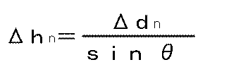
の関係式に基づいて、Δhnが算出できる(図6では、n=3の場合を図示している)。
本発明を適用させた場合、基板10の突出部10を適宜所定の撮像範囲に区分けし、区分けした撮像範囲毎に2つの観察部により同時に撮像する。そして、撮像した画像に含まれる各輝点情報から、それぞれの突出部の頭頂部の高さのばらつきを算出することができる。
本発明を適用させた場合、基板10の突出部10を適宜所定の撮像範囲に区分けし、区分けした撮像範囲毎に2つの観察部により同時に撮像する。そして、撮像した画像に含まれる各輝点情報から、それぞれの突出部の頭頂部の高さのばらつきを算出することができる。
[ライン光三角測量法]
上述のステレオ観察法に基づく測定方法では、各突出部の頭頂部同士の高さのばらつきを求めることはできるが、突出部10bの基板10の表面からの高さhを求めることができない。基板平面から反射される光の光量が、前記頭頂部からの反射光と比較して、強すぎたり弱すぎたりして、基板平面部の所定の場所を特定するのが困難だからである。
また、基板平面から反射される光の光量が適切であったとしても、同様な配線パターンが並んでいる場合や、配線パターンが全く無い場合には2つのカメラで撮像される同一点の特定は出来ない。
そのため、基板10の表面に向けて、第3の方向からライン状の第3の照明光52を照射し、その反射光を第3撮像部で撮像し、三角測量の原理を用いて突出部10bの基板10の正しい位置を測定し、後述のとおり、上述のステレオ観察法と下述する光切断を組み合わせて、突出部の基板平面からの高さの分布を算出する。
上述のステレオ観察法に基づく測定方法では、各突出部の頭頂部同士の高さのばらつきを求めることはできるが、突出部10bの基板10の表面からの高さhを求めることができない。基板平面から反射される光の光量が、前記頭頂部からの反射光と比較して、強すぎたり弱すぎたりして、基板平面部の所定の場所を特定するのが困難だからである。
また、基板平面から反射される光の光量が適切であったとしても、同様な配線パターンが並んでいる場合や、配線パターンが全く無い場合には2つのカメラで撮像される同一点の特定は出来ない。
そのため、基板10の表面に向けて、第3の方向からライン状の第3の照明光52を照射し、その反射光を第3撮像部で撮像し、三角測量の原理を用いて突出部10bの基板10の正しい位置を測定し、後述のとおり、上述のステレオ観察法と下述する光切断を組み合わせて、突出部の基板平面からの高さの分布を算出する。
図7は、本発明を具現化する形態の一例の第3の観察部で撮像された例示画像であり、第3撮像部のカメラ55で観察した画像イメージの例を示している。第3反射光53と直交する方向をY”方向と定義し、図1における第3反射光53を撮像した様子を示している。
前記画像においては、第3の照明部から照射されたライン照明51が、突出部の径よりも長いライン状の照明光として照射されており、突出部10bの頭頂部で反射した光53aが点状の光として、基板10の平面部で反射した光53bがライン状の光として撮像されている。このとき、カメラ55の撮像エリア内で観察された、頭頂部で反射した光53aの基準点10からのY”方向の距離をL1とし、基板10の平面部で反射した光53bの基準点10からの距離を、基準点とベース面までのY”方向の距離L2と定義する。
本方式では、突出部の大きさが小さいと、頭頂部で反射する光53aの光量が、基板10の平面部で反射光53bと比較して微弱となるので、前記距離L1は測定せず、基準点とベース面までのY”方向の距離L2に基づいて測定を行い、本発明を適用させる。
前記画像においては、第3の照明部から照射されたライン照明51が、突出部の径よりも長いライン状の照明光として照射されており、突出部10bの頭頂部で反射した光53aが点状の光として、基板10の平面部で反射した光53bがライン状の光として撮像されている。このとき、カメラ55の撮像エリア内で観察された、頭頂部で反射した光53aの基準点10からのY”方向の距離をL1とし、基板10の平面部で反射した光53bの基準点10からの距離を、基準点とベース面までのY”方向の距離L2と定義する。
本方式では、突出部の大きさが小さいと、頭頂部で反射する光53aの光量が、基板10の平面部で反射光53bと比較して微弱となるので、前記距離L1は測定せず、基準点とベース面までのY”方向の距離L2に基づいて測定を行い、本発明を適用させる。
図8は、本発明を具現化する形態の一例を示す正面図であり、図1を側面から(つまり、X方向の矢印方向に)見た様子を示している。
第3の照射光52は、基板10に向けて第3の方向から、基板10の表面と所定の角度θ3をなして照射され、突出部の頭頂部で反射した光53aと、基板10の表面から反射した光53bとでなす角度は、基板10の表面と所定の角度θ3をなしている。
第3の照射光52は、基板10に向けて第3の方向から、基板10の表面と所定の角度θ3をなして照射され、突出部の頭頂部で反射した光53aと、基板10の表面から反射した光53bとでなす角度は、基板10の表面と所定の角度θ3をなしている。
このとき、基準点RPとし、その部分から角度θ3で反射した光53zがカメラ55で観察される位置をLzと定義する。
基準点RPの基板10表面からの高さh0と、カメラ55で観察した基準点RPで反射した光53zと基板10表面で反射した光53bとの距離L2との間には、
基準点RPから基板10の表面までの距離をL’と定義すると、
L2=L’・sin2θ3
h0=L’・sinθ3
の関係が成立し、観察された画像に基づいて算出されたずれ量L2から、
基準点RPの基板10表面からの高さh0と、カメラ55で観察した基準点RPで反射した光53zと基板10表面で反射した光53bとの距離L2との間には、
基準点RPから基板10の表面までの距離をL’と定義すると、
L2=L’・sin2θ3
h0=L’・sinθ3
の関係が成立し、観察された画像に基づいて算出されたずれ量L2から、
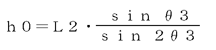
の関係式に基づいて、h0が算出できる。
実際の各頭頂部の高さHnは、Z方向,Y’方向,Y”方向の矢印の方向をプラス成分として表すと、
数式1,2のΔhn および 数式3の0 から、n番目の突出部の頭頂部の、基板10表面からの高さHnは、
実際の各頭頂部の高さHnは、Z方向,Y’方向,Y”方向の矢印の方向をプラス成分として表すと、
数式1,2のΔhn および 数式3の0 から、n番目の突出部の頭頂部の、基板10表面からの高さHnは、

によって、算出できる。
[基準点と突出部の頭頂部高さとのオフセット調整]
上述のステレオ観察法により算出された高さのばらつきΔhnと、上述のライン光三角測量法により算出された基準点RPの基板10表面からの高さh0とは、下述のように演算して、オフセット調節を行う(図6,8を参照)。
上述のステレオ観察法により算出された高さのばらつきΔhnと、上述のライン光三角測量法により算出された基準点RPの基板10表面からの高さh0とは、下述のように演算して、オフセット調節を行う(図6,8を参照)。
先ず、格子状のパターンが形成されたキャリブレーションツール10cを準備し、それらの模様を、カメラ35,45で撮像する。このとき、クロム膜10pは、厚みが既知で均一な金属膜であり、表面反射した光がカメラ35,45を用いてステレオ観察される。
さらに、キャリブレーションツール10cの石英面(つまり、格子状のパターンの底部)は、ライン状の第3の照明光52とカメラ55を用いて、石英面からの反射光が観察される。
さらに、キャリブレーションツール10cの石英面(つまり、格子状のパターンの底部)は、ライン状の第3の照明光52とカメラ55を用いて、石英面からの反射光が観察される。
このとき、クロム膜10pの表面に基準点RPがあり、基準点RPと基板面との高さの差がh0であったとする。
そして、上述のステレオ観察法(図6参照)により算出された、n番目の突出部の高さHnのばらつきΔhnを、基準点PRの高さh0に対する頭頂部の高さに対するばらつきとして算出する。
そうすると、ステレオ観察法により観察された画像に基づいて算出されるずれ量Δdnと、ライン光三角測量法により観察された画像に基づいて算出されたずれ量L2とから、実際の突出部の頭頂部の高さHnが算出できる。
そして、上述のステレオ観察法(図6参照)により算出された、n番目の突出部の高さHnのばらつきΔhnを、基準点PRの高さh0に対する頭頂部の高さに対するばらつきとして算出する。
そうすると、ステレオ観察法により観察された画像に基づいて算出されるずれ量Δdnと、ライン光三角測量法により観察された画像に基づいて算出されたずれ量L2とから、実際の突出部の頭頂部の高さHnが算出できる。
[観察・測定フロー]
図9は、本発明を具現化する形態の一例の動作フローを示すフロー図であり、基板10に多数ある突出部10bをいくつかのエリア毎に区分けして逐次移動及び観察を繰り返し、それぞれの突出部の高さを算出する一連のフローが、ステップ毎に示されている。
図9は、本発明を具現化する形態の一例の動作フローを示すフロー図であり、基板10に多数ある突出部10bをいくつかのエリア毎に区分けして逐次移動及び観察を繰り返し、それぞれの突出部の高さを算出する一連のフローが、ステップ毎に示されている。
先ず、基板10を突出部高さ測定装置1のテーブル23に載置する(s101)。
続いて、観察位置にテーブル23を移動させ(s102)、観察エリア10fに向けて第1の方向から第1の照明光32を照射させ(s113)、反射した光を前記第1撮像部で観察する(s114)。
その後、観察エリア10fに向けて第2の方向から第2の照明光42を照射させ(s123)、反射した光を前記第2撮像部で観察する(s124)。
その後、観察エリア10fに向けて第3の方向からライン状の第3の照明光52を照射させ(s133)、反射した光を前記第3撮像部で観察する(s134)。
そうして、観察エリア10f内のそれぞれの突出部10bのベース面からの高さを算出する(s105)。
次に、全ての観察対象エリアについて観察がされたかどうかを判断し(s106)、引き続き観察すべき観察対象エリアがあれば、その場所にテーブル23を移動させ、上述のステップs102,s113~s134,105を繰り返す。全ての観察が終了していると判断されれば、各観察エリア内で算出された結果を合成し、基板10内の全ての突出部10bの高さとして算出する(s107)。
全ての突出部10bの高さの算出が終われば、テーブル23を基板受渡位置へ移動させ(s108)、テーブル23から基板10を取り出す(s109)。
続いて、観察位置にテーブル23を移動させ(s102)、観察エリア10fに向けて第1の方向から第1の照明光32を照射させ(s113)、反射した光を前記第1撮像部で観察する(s114)。
その後、観察エリア10fに向けて第2の方向から第2の照明光42を照射させ(s123)、反射した光を前記第2撮像部で観察する(s124)。
その後、観察エリア10fに向けて第3の方向からライン状の第3の照明光52を照射させ(s133)、反射した光を前記第3撮像部で観察する(s134)。
そうして、観察エリア10f内のそれぞれの突出部10bのベース面からの高さを算出する(s105)。
次に、全ての観察対象エリアについて観察がされたかどうかを判断し(s106)、引き続き観察すべき観察対象エリアがあれば、その場所にテーブル23を移動させ、上述のステップs102,s113~s134,105を繰り返す。全ての観察が終了していると判断されれば、各観察エリア内で算出された結果を合成し、基板10内の全ての突出部10bの高さとして算出する(s107)。
全ての突出部10bの高さの算出が終われば、テーブル23を基板受渡位置へ移動させ(s108)、テーブル23から基板10を取り出す(s109)。
上述のステレオ観察法に基づく観察においては、第1の照明光及び第2の照明光とは、主波長が同じであれば、同時に発光させるのではなく、発光タイミングを少しずらすことが好ましい。この場合、それぞれの発光時間が短時間であれば、1つの観察エリアを撮像する時間はさほど増加させることなく測定ができる。そして、第1の照明光及び第2の照明光とを同じ主波長にできるので、照明やカメラ、フィルタなどの部品を共通化することができ、専用部品を個別に用意する必要がなくなる。そのため、装置や保守のコストダウンを図ることができるという効果を奏する。
また、発光時間がごく僅かであれば、発光時間及び撮像タイミングをずらすことで、他方の照明による輝点を検出しないので、本発明を適用できる。
ライン状の第3の照明光52は、観察エリア10fの外に照射しても本発明を適用することはできるが、観察エリア10f内に照射することが好ましい。そうすれば、第3の照明光が基板表面からはみ出してしまうことを防ぐことができる。このとき、第3の照明光52は、第1及び第2の照明光32,33と同じ主波長であれば、発光タイミングを少しずらせば良く、第1~第3の照明光の発光時間及び撮像時間並びに、次の発光までの時間がごく僅かの場合は、上述のステップs112~s134は、ほぼ同時に行うことができるといえる。
また、発光時間がごく僅かであれば、発光時間及び撮像タイミングをずらすことで、他方の照明による輝点を検出しないので、本発明を適用できる。
ライン状の第3の照明光52は、観察エリア10fの外に照射しても本発明を適用することはできるが、観察エリア10f内に照射することが好ましい。そうすれば、第3の照明光が基板表面からはみ出してしまうことを防ぐことができる。このとき、第3の照明光52は、第1及び第2の照明光32,33と同じ主波長であれば、発光タイミングを少しずらせば良く、第1~第3の照明光の発光時間及び撮像時間並びに、次の発光までの時間がごく僅かの場合は、上述のステップs112~s134は、ほぼ同時に行うことができるといえる。
[バリエーション]
一方、撮影時間をより短くしたい場合は、第1の照明光と第2の照明光とは、異なる主波長成分とし、第1撮像部は第1の照明光の主波長のみを撮像し、第2撮像部は第2の照明光の主波長のみを撮像する形態とすることが好ましい。例えば、第1の照明光として赤色照明を用い、第1撮像部には、赤色の波長領域のみを透過させるバンドパスフィルタFrを用い、第2の照明光として緑色照明を用い、第2撮像部には、緑色の波長領域のみを透過させるバンドパスフィルタFgを用いる。そうすれば、第1撮像部に入射する緑色の照明光は前記フィルタFrで吸収され、第2撮像部に入射する赤色の照明光は前記フィルタFgで吸収される。よって、第1及び第2の照明光を、同時に発光させても、他方の照明による輝点を検出しない。そうすることで、第1の照明光と第2の照明光とを同時に照射し、2つの撮像部で同時に撮影しても、観察すべき輝点の位置を誤検出することを防止できる。そのため、観察すべき場所が多くある場合でも、撮像時間をより短くできるという効果を奏する。このとき、第1の照明光と第2の照明光とを、異なる主波長成分とする具体的な例としては、前述の様に、色の異なる照明(例えば、赤・緑・青色のLED照明など)を用いて、照明光の主波長成分を変える場合や、共通する波長特性の照明(例えば、白色照明など)を用いるが、特定の波長成分を通すバンドパスフィルタを用いてそれぞれの透過できる主波長成分を変えて用いる場合などが挙げられる。
また、ライン状の第3の照明光52も、第1及び第2の照明光とは異なる主波長成分とすることが好ましい。そうすることで、第1~第3の照明光32,42,52を観察エリア10f内に同時に照射しても、互いの照明光の主波長が、他の観察部での測定に影響を与えることが無くなる。
図10は、本発明を具現化する別の形態の一例の動作フローを示すフロー図であり、基板10に多数ある突出部10bをいくつかのエリア毎に区分けして逐次移動及び観察を繰り返し、それぞれの突出部の高さを算出する、別の形態における一連のフローが、ステップ毎に示されている。
図9を用いて説明した形態においては、ステップs113~s134を時系列的に順次行うフローとしていたが、この手順に代えて、ここで述べる別の形態では、ステップs113~s134を並行して同時に行うフローとしている。
そうすることで、上述の様に、ステップs113~s134に要する時間をより短くすることができる。
一方、撮影時間をより短くしたい場合は、第1の照明光と第2の照明光とは、異なる主波長成分とし、第1撮像部は第1の照明光の主波長のみを撮像し、第2撮像部は第2の照明光の主波長のみを撮像する形態とすることが好ましい。例えば、第1の照明光として赤色照明を用い、第1撮像部には、赤色の波長領域のみを透過させるバンドパスフィルタFrを用い、第2の照明光として緑色照明を用い、第2撮像部には、緑色の波長領域のみを透過させるバンドパスフィルタFgを用いる。そうすれば、第1撮像部に入射する緑色の照明光は前記フィルタFrで吸収され、第2撮像部に入射する赤色の照明光は前記フィルタFgで吸収される。よって、第1及び第2の照明光を、同時に発光させても、他方の照明による輝点を検出しない。そうすることで、第1の照明光と第2の照明光とを同時に照射し、2つの撮像部で同時に撮影しても、観察すべき輝点の位置を誤検出することを防止できる。そのため、観察すべき場所が多くある場合でも、撮像時間をより短くできるという効果を奏する。このとき、第1の照明光と第2の照明光とを、異なる主波長成分とする具体的な例としては、前述の様に、色の異なる照明(例えば、赤・緑・青色のLED照明など)を用いて、照明光の主波長成分を変える場合や、共通する波長特性の照明(例えば、白色照明など)を用いるが、特定の波長成分を通すバンドパスフィルタを用いてそれぞれの透過できる主波長成分を変えて用いる場合などが挙げられる。
また、ライン状の第3の照明光52も、第1及び第2の照明光とは異なる主波長成分とすることが好ましい。そうすることで、第1~第3の照明光32,42,52を観察エリア10f内に同時に照射しても、互いの照明光の主波長が、他の観察部での測定に影響を与えることが無くなる。
図10は、本発明を具現化する別の形態の一例の動作フローを示すフロー図であり、基板10に多数ある突出部10bをいくつかのエリア毎に区分けして逐次移動及び観察を繰り返し、それぞれの突出部の高さを算出する、別の形態における一連のフローが、ステップ毎に示されている。
図9を用いて説明した形態においては、ステップs113~s134を時系列的に順次行うフローとしていたが、この手順に代えて、ここで述べる別の形態では、ステップs113~s134を並行して同時に行うフローとしている。
そうすることで、上述の様に、ステップs113~s134に要する時間をより短くすることができる。
[第1の方向]
上述では第1のカメラについて、第1の方向として、基板10の表面に対して垂直に照明を照射し、垂直に反射された光を観察する形態を示した。しかし、この第1の方向は、第2の方向と異なっていれば良く、垂直以外の角度で基板10の表面に向けて照射されるものであれば良い。このとき、第1の方向から照射する照明光は、照明41と同様の形態のものを用いれば良い。
上述では第1のカメラについて、第1の方向として、基板10の表面に対して垂直に照明を照射し、垂直に反射された光を観察する形態を示した。しかし、この第1の方向は、第2の方向と異なっていれば良く、垂直以外の角度で基板10の表面に向けて照射されるものであれば良い。このとき、第1の方向から照射する照明光は、照明41と同様の形態のものを用いれば良い。
[第2撮像部のあおり補正]
上述では、第2のカメラは、斜め方向からの撮影となる。そのため、エリアセンサを使用した際に通常の光学系を使用した場合、撮像条件によっては、撮影する画像の内、視野中央のみ合焦し視野端では被写界深度を外れぼやけてしまう場合がある。ぼやけた部分の情報はその後の処理では使用できないので無駄になる。そこで撮影画像全面で合焦し単位撮影あたりの有効画像データが大きくなるように、光学系をシフト光学配置やシャインプルーフ光学配置にし、焦点深度を大きく取る形態としても良い。
上述では、第2のカメラは、斜め方向からの撮影となる。そのため、エリアセンサを使用した際に通常の光学系を使用した場合、撮像条件によっては、撮影する画像の内、視野中央のみ合焦し視野端では被写界深度を外れぼやけてしまう場合がある。ぼやけた部分の情報はその後の処理では使用できないので無駄になる。そこで撮影画像全面で合焦し単位撮影あたりの有効画像データが大きくなるように、光学系をシフト光学配置やシャインプルーフ光学配置にし、焦点深度を大きく取る形態としても良い。
[第4のライン照明と観察部]
上述した第3の観察部5とは別に、第4の観察部6をさらに備える形態とすることもできる。第4の観察部6は、第4の照明部としてのライン照明61と、第4撮像部としての鏡筒64とカメラ65とが含まれて構成されている。ライン照明61は、基板10に向けて第4の方向から所定の長さで線状の照明光62を照射することができる。
上述した第3の観察部5とは別に、第4の観察部6をさらに備える形態とすることもできる。第4の観察部6は、第4の照明部としてのライン照明61と、第4撮像部としての鏡筒64とカメラ65とが含まれて構成されている。ライン照明61は、基板10に向けて第4の方向から所定の長さで線状の照明光62を照射することができる。
ライン照明61から照射され、基板10の平面及び基板10上の突出部の頭頂部で反射された第4反射光63は、鏡筒64を通りカメラ65の撮像部に受光される。鏡筒64は、レンズなどの光学素子が組み込まれており、基板10の平面を焦点深度内に収めてカメラ65の撮像部に結像させるように構成されている。
第4の照明部から照射された光は、基板10上に、第3照明部から照射された光とは異なる部位に照射されて、反射される。そのため、第3のライン照明のみでは捕捉できなかった、第3の照明の長手方向と直交する方向の基板の傾きが、第4のライン照明を追加して測定することで、正確に捕捉できるようになる。
1 突出部高さ測定装置
2 基板移動部
3 第1の観察部
4 第2の観察部
5 第3の観察部
6 第4の観察部
9 制御部
10 基板
10b 基板上の突出部
10c キャリブレーションツール
10p 格子状のパターン
10f 観察エリア
21 Y軸ステージ
22 X軸ステージ
23 テーブル
30 光量調節ユニット
31 第1照明部
32 第1の照明光
33 第1反射光
34 鏡筒
35 カメラ
40 光量調節ユニット
41 第2照明部
42 第2の照明光
43 第2反射光
44 鏡筒
45 カメラ
50 光量調節ユニット
51 第3照明部
52 第3の照明光
53 第3反射光
54 鏡筒
55 カメラ
60 光量調節ユニット
61 第4照明部
62 第4の照明光
63 第4反射光
64 鏡筒
65 カメラ
90 制御用コンピュータ
91 情報入力部
92 情報出力部
93 発報部
94 情報記録部
95 制御ユニット
96 画像処理ユニット
2 基板移動部
3 第1の観察部
4 第2の観察部
5 第3の観察部
6 第4の観察部
9 制御部
10 基板
10b 基板上の突出部
10c キャリブレーションツール
10p 格子状のパターン
10f 観察エリア
21 Y軸ステージ
22 X軸ステージ
23 テーブル
30 光量調節ユニット
31 第1照明部
32 第1の照明光
33 第1反射光
34 鏡筒
35 カメラ
40 光量調節ユニット
41 第2照明部
42 第2の照明光
43 第2反射光
44 鏡筒
45 カメラ
50 光量調節ユニット
51 第3照明部
52 第3の照明光
53 第3反射光
54 鏡筒
55 カメラ
60 光量調節ユニット
61 第4照明部
62 第4の照明光
63 第4反射光
64 鏡筒
65 カメラ
90 制御用コンピュータ
91 情報入力部
92 情報出力部
93 発報部
94 情報記録部
95 制御ユニット
96 画像処理ユニット
Claims (8)
- 基板平面上に複数分布している突出部の前記基板平面から突出した高さを測定する突出部高さ測定装置において、
測定対象となる前記突出部を含む前記基板平面に向けて第1の方向から照明光を照射する第1照明部と、
前記第1照明部から照射されて前記突出部の頭頂部で反射された第1反射光を撮像する第1撮像部と、
測定対象となる前記突出部を含む前記基板平面に向けて第2の方向から照明光を照射する第2照明部と、
前記第2照明部から照射されて前記突出部の頭頂部で反射された第2反射光を撮像する第2撮像部とを備え、
前記第1撮像部で撮像された前記突出部の頭頂部からの反射光の位置情報と、
前記第2撮像部で撮像された前記突出部の頭頂部からの反射光の位置情報とに基づいて、前記突出部の頭頂部同士の相対高さを算出する相対高さ演算部を備え、
第3の方向から前記基板平面に向けて前記突出部の径よりも長いライン状の照明光を照射する第3照明部と、
前記第3照明部から照射されて前記基板平面上で反射された第3反射光を撮像する第3撮像部とを備え、
前記第3撮像部で撮像された前記基板平面上からの反射光の位置情報と、
前記相対高さ演算部で算出された結果に基づいて、
前記基板平面上に複数分布している各々の突出部の前記基板平面から突出した高さを算出する突出部高さ演算部を備えたことを特徴とする、突出部高さ測定装置。 - 前記第1照明部から照射される光の照射と、
前記第2照明部から照射される光の照射とが、時間をずらして行われる
ことを特徴とする、請求項1に記載の突出部高さ測定装置。 - 前記第1照明部から照射される光の主波長が、
前記第2照明部から照射される光の主波長とは異なっており、
前記第1撮像部と前記第2撮像部とは同時に撮像を行う
ことを特徴とする、請求項1に記載の突出部高さ測定装置。 - 前記第3照明部から照射される光の主波長が、
前記第1照明部及び/又は前記第2照明部から照射される光の主波長とは異なっており、前記第3撮像部と、前記第3撮像部とは異なる主波長の光を撮像する前記第1撮像部及び/又は前記第2撮像部とを、同時に撮像を行う
ことを特徴とする、請求項1~3のいずれかに記載の突出部高さ測定装置。
- 基板平面上に複数分布している突出部の前記基板平面から突出した高さを測定する突出部高さ測定方法において、
前記基板平面に向けて第1の方向から第1の照明光を照射する第1照明照射ステップと、
前記第1照明照射ステップで照射された光が前記突出部の頭頂部で反射された第1反射光を撮像する第1撮像ステップと、
前記基板平面に向けて第2の方向から照明光を照射する第2照明照射ステップと、
前記第2照明照射ステップで照射された光が前記突出部の頭頂部で反射された第2反射光を撮像する第2撮像ステップとを有し、
前記第1撮像ステップで撮像された前記突出部の頭頂部からの反射光の位置情報と、
前記第2撮像ステップで撮像された前記突出部の頭頂部からの反射光の位置情報とに基づいて、
前記突出部の頭頂部同士の相対高さを算出する相対高さ演算ステップを有し、
第3の方向から前記基板平面に向けて前記突出部の径よりも長いライン状の照明光を照射する第3照明照射ステップと、
前記第3照明照射ステップで照射されて前記基板平面上で反射された第3反射光を撮像する第3撮像ステップとを有し、
前記第3撮像ステップで撮像された前記基板平面上からの反射光の位置情報と、
前記相対高さ演算ステップで算出された結果に基づいて、
前記基板平面上に複数分布している各々の突出部の前記基板平面から突出した高さを算出する突出部高さ演算ステップを有することを特徴とする、突出部高さ測定方法。 - 前記第1照明照射ステップと、前記第2照明照射ステップとを、
時間をずらして行うことを特徴とする、請求項5に記載の突出部高さ測定方法。 - 前記第1照明照射ステップで照射される光の主波長が、
前記第2照明照射ステップで照射される光の主波長とは異なっており、
前記第1撮像ステップと前記第2撮像ステップとを同時に行う
ことを特徴とする、請求項5に記載の突出部高さ測定方法。 - 前記第3照明照射ステップで照射される光の主波長が、
前記第1照明照射ステップ及び/又は前記第2照明照射ステップから照射される光の主波長とは異なっており、
前記第3撮像ステップを、前記第3撮像ステップとは異なる主波長の光を撮像する前記第1撮像ステップ及び/又は前記第2撮像ステップと同時に撮像を行う
ことを特徴とする、請求項5~7に記載の突出部高さ測定方法。
Applications Claiming Priority (2)
| Application Number | Priority Date | Filing Date | Title |
|---|---|---|---|
| JP2011-077360 | 2011-03-31 | ||
| JP2011077360 | 2011-03-31 |
Publications (1)
| Publication Number | Publication Date |
|---|---|
| WO2012132865A1 true WO2012132865A1 (ja) | 2012-10-04 |
Family
ID=46930602
Family Applications (1)
| Application Number | Title | Priority Date | Filing Date |
|---|---|---|---|
| PCT/JP2012/056336 Ceased WO2012132865A1 (ja) | 2011-03-31 | 2012-03-13 | 突出部高さ測定装置及び方法 |
Country Status (2)
| Country | Link |
|---|---|
| TW (1) | TW201241412A (ja) |
| WO (1) | WO2012132865A1 (ja) |
Cited By (1)
| Publication number | Priority date | Publication date | Assignee | Title |
|---|---|---|---|---|
| JP2020153885A (ja) * | 2019-03-22 | 2020-09-24 | ヤマハ発動機株式会社 | 計測装置および表面実装機 |
Families Citing this family (2)
| Publication number | Priority date | Publication date | Assignee | Title |
|---|---|---|---|---|
| WO2022013703A1 (en) | 2020-07-13 | 2022-01-20 | Camtek Ltd. | Continuous bump measurement height metrology |
| KR20230144924A (ko) * | 2022-04-08 | 2023-10-17 | 비트록스 테크놀로지스 에스디엔. 비에이치디. | 패키징된 칩의 접촉 높이를 결정하는 시스템 및 방법 |
Citations (7)
| Publication number | Priority date | Publication date | Assignee | Title |
|---|---|---|---|---|
| JPH09329422A (ja) * | 1996-06-12 | 1997-12-22 | Fujitsu Ltd | 高さ測定方法及び装置 |
| JPH10239025A (ja) * | 1996-12-25 | 1998-09-11 | Hitachi Tobu Semiconductor Ltd | 外観検査方法および装置 |
| JPH11287628A (ja) * | 1998-04-02 | 1999-10-19 | Omron Corp | 高さ測定装置および高さ測定方法および観測装置 |
| JP2002267415A (ja) * | 2001-03-08 | 2002-09-18 | Nec Corp | 半導体測定装置 |
| JP2002334898A (ja) * | 2001-05-09 | 2002-11-22 | Ibiden Co Ltd | バンプ高さ検査方法および検査装置 |
| JP2003329418A (ja) * | 2002-05-15 | 2003-11-19 | Kawasaki Heavy Ind Ltd | 3次元計測装置 |
| JP2007093412A (ja) * | 2005-09-29 | 2007-04-12 | Fujinon Corp | 3次元形状測定装置 |
-
2012
- 2012-03-07 TW TW101107596A patent/TW201241412A/zh unknown
- 2012-03-13 WO PCT/JP2012/056336 patent/WO2012132865A1/ja not_active Ceased
Patent Citations (7)
| Publication number | Priority date | Publication date | Assignee | Title |
|---|---|---|---|---|
| JPH09329422A (ja) * | 1996-06-12 | 1997-12-22 | Fujitsu Ltd | 高さ測定方法及び装置 |
| JPH10239025A (ja) * | 1996-12-25 | 1998-09-11 | Hitachi Tobu Semiconductor Ltd | 外観検査方法および装置 |
| JPH11287628A (ja) * | 1998-04-02 | 1999-10-19 | Omron Corp | 高さ測定装置および高さ測定方法および観測装置 |
| JP2002267415A (ja) * | 2001-03-08 | 2002-09-18 | Nec Corp | 半導体測定装置 |
| JP2002334898A (ja) * | 2001-05-09 | 2002-11-22 | Ibiden Co Ltd | バンプ高さ検査方法および検査装置 |
| JP2003329418A (ja) * | 2002-05-15 | 2003-11-19 | Kawasaki Heavy Ind Ltd | 3次元計測装置 |
| JP2007093412A (ja) * | 2005-09-29 | 2007-04-12 | Fujinon Corp | 3次元形状測定装置 |
Cited By (2)
| Publication number | Priority date | Publication date | Assignee | Title |
|---|---|---|---|---|
| JP2020153885A (ja) * | 2019-03-22 | 2020-09-24 | ヤマハ発動機株式会社 | 計測装置および表面実装機 |
| JP7271250B2 (ja) | 2019-03-22 | 2023-05-11 | ヤマハ発動機株式会社 | 計測装置および表面実装機 |
Also Published As
| Publication number | Publication date |
|---|---|
| TW201241412A (en) | 2012-10-16 |
Similar Documents
| Publication | Publication Date | Title |
|---|---|---|
| KR101273094B1 (ko) | 광삼각법을 이용한 3차원 형상 측정기를 사용하여 pcb 범프 높이 측정 방법 | |
| US7126699B1 (en) | Systems and methods for multi-dimensional metrology and/or inspection of a specimen | |
| JP5421763B2 (ja) | 検査装置および検査方法 | |
| JP5944850B2 (ja) | 欠陥検査方法及びこれを用いた装置 | |
| JP5109633B2 (ja) | 測定方法及び検査方法並びに測定装置及び検査装置 | |
| CN100585615C (zh) | 检测系统 | |
| JP5659396B2 (ja) | 接合部検査装置 | |
| KR101659302B1 (ko) | 3차원 형상 측정장치 | |
| WO2023160133A1 (en) | A differential light-section line-scanning profilometry based on multi-angle projection of incoherent light sources | |
| JP2011013222A (ja) | 基板検査装置及び検査方法 | |
| US20120133920A1 (en) | High speed, high resolution, three dimensional printed circuit board inspection system | |
| TW201825866A (zh) | 接合裝置以及被攝體的高度檢測方法 | |
| TW201740484A (zh) | 視覺化檢驗裝置 | |
| CN103733019B (zh) | 用于确定集成电路封装的共面性的方法和装置 | |
| JP2013228264A (ja) | 突出部高さ測定装置 | |
| WO2012132865A1 (ja) | 突出部高さ測定装置及び方法 | |
| JP6684992B2 (ja) | 突起検査装置及びバンプ検査装置 | |
| JP3978507B2 (ja) | バンプ検査方法及び装置 | |
| CN113764299A (zh) | 凸块高度的检测装置及方法 | |
| KR102615980B1 (ko) | 오버레이 계측 장치 및 오버레이 계측 방법 | |
| JP5541646B2 (ja) | ライン照明装置 | |
| JP2002267415A (ja) | 半導体測定装置 | |
| JP6893842B2 (ja) | パターン検査方法およびパターン検査装置 | |
| JP2004134585A (ja) | 球体または半球体の高さ計測方法 | |
| KR100807119B1 (ko) | 프로빙 검사장치용 광학 시스템 및 이를 이용하는 프로빙검사 방법 |
Legal Events
| Date | Code | Title | Description |
|---|---|---|---|
| 121 | Ep: the epo has been informed by wipo that ep was designated in this application |
Ref document number: 12763531 Country of ref document: EP Kind code of ref document: A1 |
|
| NENP | Non-entry into the national phase |
Ref country code: DE |
|
| 122 | Ep: pct application non-entry in european phase |
Ref document number: 12763531 Country of ref document: EP Kind code of ref document: A1 |
|
| NENP | Non-entry into the national phase |
Ref country code: JP |