WO2012132794A1 - ベルト式無段変速機のエレメント及びベルト - Google Patents
ベルト式無段変速機のエレメント及びベルト Download PDFInfo
- Publication number
- WO2012132794A1 WO2012132794A1 PCT/JP2012/055740 JP2012055740W WO2012132794A1 WO 2012132794 A1 WO2012132794 A1 WO 2012132794A1 JP 2012055740 W JP2012055740 W JP 2012055740W WO 2012132794 A1 WO2012132794 A1 WO 2012132794A1
- Authority
- WO
- WIPO (PCT)
- Prior art keywords
- belt
- variable transmission
- continuously variable
- pair
- rings
- Prior art date
- Legal status (The legal status is an assumption and is not a legal conclusion. Google has not performed a legal analysis and makes no representation as to the accuracy of the status listed.)
- Ceased
Links
Images





Classifications
-
- F—MECHANICAL ENGINEERING; LIGHTING; HEATING; WEAPONS; BLASTING
- F16—ENGINEERING ELEMENTS AND UNITS; GENERAL MEASURES FOR PRODUCING AND MAINTAINING EFFECTIVE FUNCTIONING OF MACHINES OR INSTALLATIONS; THERMAL INSULATION IN GENERAL
- F16G—BELTS, CABLES, OR ROPES, PREDOMINANTLY USED FOR DRIVING PURPOSES; CHAINS; FITTINGS PREDOMINANTLY USED THEREFOR
- F16G5/00—V-belts, i.e. belts of tapered cross-section
- F16G5/16—V-belts, i.e. belts of tapered cross-section consisting of several parts
Definitions
- the present invention relates to a belt stretched over a pulley of a belt type continuously variable transmission and an element constituting the belt.
- a belt for a continuously variable transmission is configured by laminating a large number of plate-like elements in the thickness direction and binding them by sandwiching two sets of rings on both sides of the element.
- a locking edge serving as a center of oscillation in the belt circumferential direction with respect to the adjacent element, and the ring An element is known in which the ring contact surface with which the inner peripheral surface comes into contact is made the same height (for example, see Patent Document 1).
- the present invention has been made paying attention to the above-mentioned problem, and is a belt type continuously variable transmission capable of reducing the friction loss by suppressing the slip of the element and the ring and reducing the stress concentration and improving the durability of the element.
- the object is to provide an element and belt.
- a body portion and a neck portion And a pair of saddle grooves in a belt-type continuously variable transmission element in which a large number of layers are laminated in the thickness direction and are annularly fixed by two sets of rings to form a continuously variable transmission belt, a body portion and a neck portion And a pair of saddle grooves.
- the body portion is sandwiched between the groove portions of the pulley of the belt-type continuously variable transmission, supports the pulley pressing force by the flank portions on both sides, and comes into contact with the pair of concave portions, the pair of convex portions, the locking edge portion, and the like. And a surface.
- the neck portion extends from a central portion in the width direction of the body portion, and connects the body portion and an ear portion extending in the width direction of the body portion.
- the pair of saddle grooves are formed on both sides of the neck portion, open to both sides of the body portion, and the pair of rings are inserted respectively.
- the pair of recesses are formed inside each of the saddle grooves and have a ring contact surface with which the inner peripheral surface of the ring contacts.
- the pair of convex portions are formed at the open side end portions of the respective saddle grooves, and protrude toward the ear portion side from the ring contact surface.
- the rocking edge portion is formed on the front surface in the belt rotation direction and serves as a center of oscillation in the belt circumferential direction with respect to adjacent elements.
- the abutting surface is formed on the ear portion side of the rocking edge portion, and is formed on a front surface of the convex portion in the belt rotation direction, on the rear side in the belt traveling direction of the adjacent element. Contact the surface.
- the element of the belt type continuously variable transmission according to the present invention is generated when the rear element pushes the front element in the traveling direction of the element while reducing the friction loss caused by the relative sliding of the element and the ring.
- the durability of the element can be improved by reducing the increase in surface pressure and stress concentration. In other words, if the recess is deepened and the ring contact surface is brought closer to the locking edge, the offset between the ring inner peripheral surface and the rocking edge that is the center of oscillation is reduced, and the slippage between the element and the ring caused by the offset is also reduced. be able to.
- the element of the present invention relaxes this stress concentration by forming a contact surface on the convex portion.
- the convex portion is formed on both sides of the body, that is, near the side end portion of the body that receives the input torque transmitted from the pulley, compared to the case where the contact surface is formed only in the central portion of the body, The position where the input torque is transmitted from the pulley and the position where the front element is pushed can be made closer. For this reason, the bending moment which arises in a body can be made small, stress concentration can be relieved, and the durability of an element can be improved.
- FIG. 1 A perspective view which shows two sets of pulleys of the maximum deceleration state with the belt-type continuously variable transmission which applied the element of Example 1 to the belt.
- FIG. 1 A perspective view which shows two sets of pulleys of the maximum deceleration state with the belt-type continuously variable transmission which applied the element of Example 1 to the belt.
- FIG. 1 A perspective view which shows two sets of pulleys of the maximum deceleration state with the belt-type continuously variable transmission which applied the element of Example 1 to the belt.
- FIG. 1 A front view when the element of Example 1 is applied to the belt for continuously variable transmission
- (b) is a side view of the element of Example 1
- FIG. It is an enlarged view of the A section shown in FIG. (A) is sectional drawing of the belt for continuously variable transmission of a 1st comparative example
- (b) is a side view of an element when the belt for continuously variable transmission of a 1st comparative example is comprised.
- Example 1 a mode for realizing an element and a belt of a belt type continuously variable transmission according to the present invention will be described based on Example 1 shown in the drawings.
- FIG. 1 is a perspective view showing two sets of pulleys in a maximum deceleration state in a belt-type continuously variable transmission in which the element of Embodiment 1 is applied to a belt.
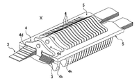
- FIG. 2 is an enlarged perspective view showing a part of a continuously variable transmission belt to which the element of the first embodiment is applied.
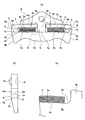
- 3A is a front view when the element of Example 1 is applied to a continuously variable transmission belt
- FIG. 3B is a side view of the element of Example 1
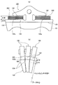
- FIG. It is an enlarged view of the A section shown in FIG.
- the belt-type continuously variable transmission to which the element of the first embodiment is applied includes an input-side pulley 1, an output-side pulley 2, and a continuously-variable transmission belt V spanned between both pulleys 1 and 2. is doing.
- the torque from the engine (not shown) is transmitted to the input pulley 1 through a torque converter and a forward / reverse switching mechanism, and the reduction gear (not shown) from the output pulley 2 via the continuously variable transmission belt V. And it is transmitted to the tire through the drive shaft.
- the input pulley 1 has a fixed pulley 11 and a slide pulley 12, and the groove width is variable in the input shaft direction.
- the output pulley 2 has a fixed pulley 21 and a slide pulley 22, and the groove width is variable in the output shaft direction.
- the pulleys 11, 12, 21, and 22 are formed with sheave surfaces 11a, 12a, 21a, and 22a in contact with the continuously variable transmission belt V.
- the slide pulleys 12 and 22 generate a pressing force in the direction in which the belt V is clamped by the piston hydraulic pressure.
- the continuously variable transmission belt V includes two sets of stacked rings (rings) 3 and 3, elements 4 stacked in the thickness direction, and two sets of spacer rings (spacers 5) and 5).
- two sets of laminated rings 3 and 3 are inserted into the saddle grooves 4d and 4d of the elements 4,.
- the elements 4,... Are sandwiched from both sides by the rings 3, 3, and a large number of elements 4,. Consists of.
- the elements 4,... 3 supports and the elements 4,... Support the pressing force from the two sets of pulleys 1 and 2.
- the two sets of laminated rings 3 and 3 are a plurality of belt-shaped rings that are welded at both ends of a thin plate of a maximum strength material equivalent to maraging steel having a thickness of about 0.2 mm, and slightly different in diameter.
- the belt-like rings are stacked in layers from the inside to the outside.
- the cross-sectional shape of these laminated rings 3 and 3 has a rectangular parallelepiped shape.
- the elements 4,... are formed of a steel plate having a thickness of about 2 mm.
- the body portion 4a is a plate member sandwiched between the groove portions of the two sets of pulleys 1 and 2, that is, the sheave surfaces 11a and 12a and the sheave surfaces 21a and 22a.
- the flank surfaces (flank portions) 4k, 4k on both sides in the width direction come into contact with the sheave surfaces 11a, 12a, 21a, 22a of the pulleys 1, 2 to support the pressing force from the pulleys 1, 2.
- the neck portion 4b is formed to extend in the outer diameter direction of the pulleys 1 and 2 from the central portion in the width direction of the body portion 4a.
- the neck portion 4b connects the body portion 4a and the ear portions 4c and 4c.
- the neck portion 4b has a smooth R at the rising portion from the body portion 4a.
- the ear portions 4c and 4c are formed to extend from both sides of the neck portion 4b in the width direction of the body portion 4a.
- edge part 4c, 4c is located inside element 4, ... rather than the flank surfaces 4k, 4k.
- the saddle grooves 4d and 4d are defined between the body portion 4a and the ear portions 4c and 4c at positions on both sides of the neck portion 4b.
- the saddle grooves 4d and 4d are opened to both sides of the body portion 4a, and two sets of laminated rings 3 and 3 are inserted.
- the nose portion 4e is formed at the upper center position of the neck portion 4b and protrudes in the traveling (rotating) direction of the belt V.
- the hole portion 4f is a dent of a size that allows the nose portion 4e to be fitted to the back surface position of the elements 4,... Corresponding to the set position of the nose portion 4e, that is, the rear side surface 4n in the traveling direction of the belt V. Is formed.
- the rocking edge portion 4g is a top edge portion of a convex portion formed on the front side surface 4m in the traveling direction of the belt V of the body portion 4a. It becomes a dynamic center.
- the recesses 4h, 4h are dents having ring contact surfaces 4o, 4o with which the inner peripheral surfaces 3a, 3a of the laminated rings 3, 3 are in contact, and are formed inside the saddle grooves 4d, 4d. That is, the concave portions 4h and 4h are formed by denting both sides of the neck portion 4b among the end surfaces facing the ear portions 4c and 4c of the body portion 4a.
- the laminated rings 3 are fitted into the recesses 4h and 4h, respectively.
- the convex portions 4i and 4i are projecting portions projecting toward the ear portions 4c and 4c from the ring contact surfaces 4o and 4o, and are formed at the open end portions of the saddle grooves 4d and 4d. That is, the convex portions 4i and 4i are formed by projecting both end portions of the upper surface facing the ear portions 4c and 4c of the body portion 4a from the ring contact surfaces 4o and 4o.
- the rising portions of the convex portions 4i, 4i from the ring contact surfaces 4o, 4o are smooth R.
- the abutment surfaces 4j, ... are the front side surfaces 4m of the convex portions 4i, 4i and the neck portion 4b in the traveling direction of the belt V, and are formed at positions closer to the ear portions 4c, 4c than the locking edge portion 4g. Yes. These abutting surfaces 4j, ... abut against the rear side surface 4n of the adjacent elements 4, ... in the traveling direction of the belt V.
- the ring contact surfaces 4o, 4o and the locking edge portion 4g are provided at the same height level in the height direction (vertical direction in FIG. 3A). Further, as shown in FIG. 3C, the ring contact surfaces 4o and 4o have a saddle shape slightly curved in an arc shape in a direction protruding toward the ear portions 4c and 4c. On the other hand, the laminated rings 3 and 3 also have a bowl shape along the ring contact surfaces 4o and 4o, and the center of the ring contact surfaces 4o and 4o and the center of the elements 4,. Alignment is possible to match at the same position in the width direction.
- the spacer rings 5 and 5 are Teflon (registered trademark) band-like rings, which are inserted between the laminated rings 3 and 3 fitted in the recesses 4h and 4h and the ear portions 4c and 4c. 3 and the dimension adjustment between the ear parts 4c and 4c are performed.
- the spacer rings 5, 5 prevent the outer surfaces 5 a, 5 a from coming into contact with the sheave surfaces 11 a, 12 a, 21 a, 22 a of the pulleys 1, 2 from the saddle grooves 4 d, 4 d.
- spacer rings 5 and 5 are provided with stepped portions 5b and 5b on the inner peripheral surface, and are in contact with the laminated rings 3 and 3 and the projecting portions 4i and 4i while being slightly fixed between the ear portions 4c and 4c.
- a small gap H (here, about 0.15 mm) is maintained.
- FIG. 4A is a cross-sectional view of a continuously variable transmission belt of the first comparative example
- FIG. 4B is a side view of the element when the continuously variable transmission belt of the first comparative example is configured.
- FIGS. 5A and 5B are explanatory views for explaining the principle of occurrence of slippage between the laminated ring and the element, where FIG. 5A shows the small diameter side and FIG. 5B shows the large diameter side.
- FIG. 6 is a graph showing the relationship between the transmission ratio and the slip amount between the element and the ring in the continuously variable transmission belt of the first comparative example.
- the continuously variable transmission belt V is usually composed of a large number of elements 100, ... and two sets of laminated rings 200, 200.
- the elements 100,... are formed by precisely punching a steel plate having a thickness of about 2 mm and have flank surfaces 101, 101 in contact with the pulleys 1, 2 on both sides.
- the two sets of laminated rings 200 and 200 are each formed by laminating rings in which thin sheets of maraging steel each having a thickness of about 0.2 mm are formed into an annular shape.
- hundreds of elements 100,... are stacked in the thickness direction, and left and right of the pair of saddle grooves 102, 102 provided on both sides of each element 100,.
- Two sets of laminated rings 200, 200 are inserted and fixed in an annular shape.
- the front surface of the elements 100 that is, the front side surface 103 in the traveling direction of the belt V is convex.
- the elements 100,... Must also be arranged in an arc shape. Therefore, the element 100,... Has a rocking edge portion 104 that is the top of the convex front side surface 103 as a fulcrum.
- the belt V swings in the circumferential direction.
- the length from the center of the pulleys 1 and 2 to the rocking edge portion 104 is defined as the pitch radius P of the belt V.
- the transmission ratio of the continuously variable transmission is determined by the ratio of the pitch radii P of the pulleys 1 and 2.
- a contact surface 105 which is a highly accurate plane having a height dimension ⁇ H1, is secured between the locking edge portion 104 and the ring contact surfaces 102a, 102a of the saddle grooves 102, 102.
- ⁇ H1 is offset in the outer diameter direction of the pulleys 1 and 2. Furthermore, since the laminated rings 200 and 200 have a thickness of ⁇ H2, the outermost ring of the laminated rings 200 and 200 is offset further outward by ⁇ H1 + ⁇ H2 than the pitch radius P.
- slip occurs inside the belt V.
- This slip is a speed ratio other than the constant speed ratio, and occurs on the side where the winding radius of the belt V wound around the pulleys 1 and 2 becomes smaller, and does not occur on the side where the larger diameter.
- the laminated rings 200, 200 rotate on the small diameter side while maintaining the speed determined on the large diameter side and the speed on the large diameter side is maintained even on the small diameter side, the movement trajectory of the elements 100,.
- the innermost ring 201 that is offset to the outer diameter side by ⁇ H1 from the pitch radius P is faster by the speed difference X than the speed of the innermost ring 201 on the larger diameter side. Therefore, slip occurs between the element 100 and the innermost ring 201 on the small diameter side.
- each ring is offset in the outer diameter direction by the plate thickness, so that slip occurs between the rings.
- the amount of offset between the innermost ring 201 and the elements 100,... is calculated by ⁇ H1
- the amount of offset between the rings 200, 200 is calculated by the plate thickness of the ring.
- the slip portions increase as the number of stacked rings 200 and 200 increases.
- FIG. 6 shows the relationship between the gear ratio and the slip amount.
- the input shaft rotation speed is 6000 rpm. At this time, it can be seen that the slip ratio is larger in the high gear ratio than in the low gear ratio.
- FIG. 7A is a sectional view of a continuously variable transmission belt according to a second comparative example
- FIG. 7B is a sectional view taken along the line BB in FIG. 7A.
- a pair of ring contact surfaces 303, 303 are formed on both sides in the width direction of the elements 301,.
- a locking edge portion 304 is formed only in the central portion in the width direction.
- the ring contact surfaces 303 and 303 are lower than the rocking edge portion 304 in the belt 300 traveling direction.
- the ring contact surfaces 303 and 303 do not contact the elements 301 on the front side of the belt 300 in the traveling direction. That is, only the rocking edge portion 304 comes into contact with the front elements 301. For this reason, the transmission stress from the pulleys 1 and 2 concentrates on the center part in the width direction of the elements 301,. This stress concentration places a burden on the boundary portions 305, 305, and there is a risk that the elements 301, ... will be deformed or damaged.
- the inner peripheral surfaces 3a, 3a of the laminated rings 3, 3 are disposed at the end portions of the body portion 4a on the ear portions 4c, 4c side.
- a pair of recesses 4h, 4h having ring contact surfaces 4o, 4o that are in contact with each other is formed.
- the rocking edges 4g and the laminated rings 3 and 3 of the rocking edge 4g and the laminated rings 3 and 3 that determine the pitch radius P become the center of oscillation of the elements 4,.
- the amount of offset with the inner peripheral surfaces 3a and 3a can be reduced.
- the ring contact surfaces 4o, 4o and the locking edge portions 4g of the pair of recesses 4h, 4h are in the height direction of the elements 4,. It is provided at the same level.
- a certain slight gap H (about 0.15 mm in this case) is maintained between the spacer rings 5 and 5 and the ear portions 4c and 4c. Therefore, the spacer rings 5 and 5 are difficult to contact the elements 4. Thereby, generation
- the raised portions from the ring contact surfaces 4o, 4o of the convex portions 4i, 4i are smooth R, and a laminated ring having a rectangular parallelepiped cross section.
- the third and third ends are not fitted.
- the saddle grooves 4d and 4d are formed at positions corresponding to the convex portions 4i and 4i and the neck portion 4b formed at the respective open end portions.
- the contact surfaces 4j,... are formed on the front side surface 4m of the convex portions 4i, 4i and the neck portion 4b in the traveling direction of the belt V, and at positions closer to the ear portions 4c, 4c than the locking edge portion 4g. Yes.
- the contact surfaces 4j,... are formed not only in the width direction center of the elements 4, but also on both sides in the width direction near the flank surfaces 4k, 4k to which torque from the pulleys 1, 2 is input.
- the Rukoto is formed not only in the width direction center of the elements 4, but also on both sides in the width direction near the flank surfaces 4k, 4k to which torque from the pulleys 1, 2 is input.
- the number of stacked layers of the stacked rings 3 and 3 is set according to the torque transmission capacity, and conventionally, the sizes of the saddle grooves 4d and 4d are set according to the number of stacked layers of the rings. That is, in the conventional element, it is necessary to individually design the elements 4,... According to the torque transmission capacity in the continuously variable transmission. On the other hand, in the elements 4,... Of the belt type continuously variable transmission of the first embodiment, the number of the stacked rings 3 and 3 varies, and the size of the gap generated between the outermost ring and the ear portions 4c and 4c. Even if they are different, it can be dealt with by adjusting the thickness of the spacer rings 5 and 5.
- the contact surface 4j that contacts the rear side surface 4n of the traveling direction of the belt V is provided. For this reason, it is possible to improve the durability of the elements 4,... By suppressing the slip of the elements 4,.
- spacers (spacer rings) 5 and 5 are provided between the outer peripheral surfaces of the rings 3 and 3 fitted in the recesses 4h and 4h and the ear portions 4c and 4c. It was set as the structure inserted. Therefore, even if the number of stacked layers 3 and 3 is changed, it is not necessary to change the elements 4,.
- a neck portion 4b extending between the body portion 4a and the ear portions 4c, 4c extending in the width direction of the body portion 4a, and formed on both sides of the neck portion 4b.
- a pair of saddle grooves 4d and 4d into which the pair of rings 3 and 3 are inserted, respectively, and the body portion 4a is formed on the front side surface 4m in the rotational direction of the belt V and is adjacent to the saddle groove 4d.
- Abutting surfaces 4j that abut on the rear side surface 4n of the belt V in the rotational direction of the belt V, and the spacers 5 and 5 are formed on the outer circumferential surface of the rings 3 and 3 and the ears. It was set as the structure inserted between the parts 4c and 4c. For this reason, it is possible to improve the durability of the elements 4,... By suppressing the slip of the elements 4,.
- the outer surfaces 5a and 5a of the spacer rings 5 and 5 are in contact with the sheave surfaces 11a, 12a, 21a and 22a of the pulleys 1 and 2 to prevent the saddle grooves 4d and 4d from falling off.
- it is not limited to this.
- the length corresponding to the recesses 4h and 4h may be set so that the outer surface 6a does not contact the respective sheave surfaces 11a, 12a, 21a and 22a.
- convex portions 7 and 7 that are caught by the recessed portions 4c ′ and 4c ′ inside the ear portions 4c and 4c are provided at the inner end portions so that the spacer rings 6 and 6 do not fall off the saddle grooves 4d and 4d. . Even in this case, an increase in friction loss is prevented by providing a certain gap between the spacer rings 6 and 6 and the elements 4.
- an example of an element constituting a belt applied to a belt-type continuously variable transmission of an engine car is shown.
- the present invention is not limited to a belt-type
- the present invention can also be applied to an element constituting a belt applied to a step transmission.
- V Belt for continuously variable transmission 1 ... Input pulleys 11a, 12a ... Sheave surface 2 ... Output pulleys 21a, 22a ... Sheave surface 3 ... Laminated ring (ring) 3a ... inner peripheral surface 4 ... element 4a ... body 4b ... neck 4c ... ear 4d ... saddle groove 4e ... nose 4f ... hole 4g ... locking edge 4h ... concave 4i ... convex 4j ... contact surface 4k ... Frank surface (Frank part) 4m ... front side surface 4n ... rear side surface 4o ... ring contact surface 5 ... spacer ring (spacer)
Landscapes
- Engineering & Computer Science (AREA)
- General Engineering & Computer Science (AREA)
- Mechanical Engineering (AREA)
- Transmissions By Endless Flexible Members (AREA)
Abstract
本発明のベルト式無段変速機のエレメント4,…は、プーリ押し付け力を支えるボディ部4aと、該ボディ部4aの幅方向中央部から延在されたネック部4bと、該ネック部4bの両側に形成されて一対のリング3,3が挿入される一対のサドル溝4d,4dと、を有し、ボディ部4aは、各サドル溝4d,4dの内側に形成された一対の凹部4h,4hと、各サドル溝4d,4dの開放側端部に形成された一対の凸部4i,4iと、隣接するエレメント4,…に対してベルト周方向の揺動中心となるロッキングエッジ部4gと、該ロッキングエッジ部4gよりもイヤー部4c,4c側に形成されると共に、各凸部4i,4iのベルト回転方向の前側面4mに形成された当接面4j,…と、を有する。
Description
本発明は、ベルト式無段変速機のプーリに掛け渡されるベルトと、このベルトを構成するエレメントに関するものである。
従来、板状のエレメントをその板厚方向に多数積層し、2組のリングをエレメント両サイドに挟み込むことによって結束して無段変速機用ベルトが構成されている。そして、このベルトによる動力伝達時において、エレメントとリングが相対的に滑ることで生じる摩擦損失を軽減するため、隣接するエレメントに対して、ベルト周方向の揺動中心となるロッキングエッジと、リングの内周面が接触するリング接触面とを、同じ高さにしたエレメントが知られている(例えば、特許文献1参照)。
しかしながら、従来のベルト式無段変速機のエレメントにあっては、プーリからエレメントに伝達されるトルクがエレメント両側のフランク部を介して入力した際、この入力トルクにより、ベルト回転方向前側のエレメントに、後側のエレメントの幅方向中央部のみが接触して押す。
すなわち、従来のエレメントは、幅方向両側部に一対のリング接触面が形成され、このリング接触面に挟まれた幅方向中央部にロッキングエッジが形成されている。ここで、リング接触面はロッキングエッジよりも後方に下がっているため、中央部以外の部分が前側のエレメントに接触することはない。これにより、中央部のみが前側のエレメントに当接して、後ろ側のエレメントが前側のエレメントを押すことになり、エレメントの幅方向中央部に応力が集中してしまう。そして、この応力集中のためにエレメントの耐久性が低下するおそれがあった。
すなわち、従来のエレメントは、幅方向両側部に一対のリング接触面が形成され、このリング接触面に挟まれた幅方向中央部にロッキングエッジが形成されている。ここで、リング接触面はロッキングエッジよりも後方に下がっているため、中央部以外の部分が前側のエレメントに接触することはない。これにより、中央部のみが前側のエレメントに当接して、後ろ側のエレメントが前側のエレメントを押すことになり、エレメントの幅方向中央部に応力が集中してしまう。そして、この応力集中のためにエレメントの耐久性が低下するおそれがあった。
本発明は、上記問題に着目してなされたもので、エレメントとリングの滑りを抑えて摩擦損失を低減すると共に、応力集中を緩和してエレメントの耐久性を向上し得るベルト式無段変速機のエレメントとベルトを提供することを目的とする。
上記目的を達成するため、板厚方向に多数積層し、2組のリングにより環状に固定されて無段変速機用ベルトを形成するベルト式無段変速機のエレメントにおいて、ボディ部と、ネック部と、一対のサドル溝と、を有する。
前記ボディ部は、前記ベルト式無段変速機のプーリの溝部に挟まれ、両側のフランク部でプーリ押し付け力を支えると共に、一対の凹部と、一対の凸部と、ロッキングエッジ部と、当接面と、を有する。
前記ネック部は、前記ボディ部の幅方向中央部から延在され、前記ボディ部と前記ボディ部の幅方向に延びるイヤー部を連結する。
前記一対のサドル溝は、前記ネック部の両側に形成され、前記ボディ部の両側方にそれぞれ開放して前記一対のリングがそれぞれ挿入される。
前記一対の凹部は、前記各サドル溝の内側に形成され、前記リングの内周面が接触するリング接触面を有する。
前記一対の凸部は、前記各サドル溝の開放側端部に形成され、前記リング接触面よりも前記イヤー部側に突出する。
前記ロッキングエッジ部は、ベルト回転方向の前側の面に形成され、隣接するエレメントに対して、ベルト周方向の揺動中心となる。
前記当接面は、前記ロッキングエッジ部よりも前記イヤー部側に形成されるとともに、前記各凸部の前記ベルト回転方向の前側の面に形成され、隣接するエレメントのベルト進行方向の後側の面に当接する。
前記ボディ部は、前記ベルト式無段変速機のプーリの溝部に挟まれ、両側のフランク部でプーリ押し付け力を支えると共に、一対の凹部と、一対の凸部と、ロッキングエッジ部と、当接面と、を有する。
前記ネック部は、前記ボディ部の幅方向中央部から延在され、前記ボディ部と前記ボディ部の幅方向に延びるイヤー部を連結する。
前記一対のサドル溝は、前記ネック部の両側に形成され、前記ボディ部の両側方にそれぞれ開放して前記一対のリングがそれぞれ挿入される。
前記一対の凹部は、前記各サドル溝の内側に形成され、前記リングの内周面が接触するリング接触面を有する。
前記一対の凸部は、前記各サドル溝の開放側端部に形成され、前記リング接触面よりも前記イヤー部側に突出する。
前記ロッキングエッジ部は、ベルト回転方向の前側の面に形成され、隣接するエレメントに対して、ベルト周方向の揺動中心となる。
前記当接面は、前記ロッキングエッジ部よりも前記イヤー部側に形成されるとともに、前記各凸部の前記ベルト回転方向の前側の面に形成され、隣接するエレメントのベルト進行方向の後側の面に当接する。
よって、本発明のベルト式無段変速機のエレメントは、エレメントとリングが相対的に滑ることによって生じる摩擦損失を低減しつつ、エレメントの進行方向前側のエレメントを後ろ側のエレメントが押すときに生じる面圧の増大や応力集中を緩和して、エレメントの耐久性を向上させることができる。
つまり、凹部を深くして、リング接触面をロッキングエッジに近づければ、リング内周面と揺動中心であるロッキングエッジとのオフセットが小さくなり、そのオフセットによって生じるエレメントとリングの滑りも小さくすることができる。また、凹部を深くして、リング接触面をロッキングエッジに近づけると、ロッキングエッジよりイヤー部側に形成される当接面の面積は、その分だけ小さくなり、前側のエレメントを押すときに生じる面圧が高くなる。この面圧は、プーリからトルクが入力されるボディ部の両側に近い所がより高くなるため、ボディ部の両端部に近い所から当接部分の摩耗が進むことになり、エレメントに偏った摩耗が生じることとなる。これを回避しようとすると従来技術のように、エレメントの中央部のみに当接面を形成することが考えられる。しかし、これは、プーリからトルクが入力される位置と前側のエレメントを押す位置とが離れることになるため、エレメントに生じる曲げモーメントが大きくなり、それにともない応力集中も大きくなる。
これに対し、本発明のエレメントは、凸部に当接面を形成することにより、この応力集中を緩和している。つまり、凸部は、ボディの両側、つまり、プーリから伝達される入力トルクを受けるボディの側端部の近くに形成されるため、ボディの中央部だけに当接面を形成する場合に比べ、プーリから入力トルクが伝達される位置と前側のエレメントを押す位置とを近くすることができる。このため、ボディに生じる曲げモーメントを小さくして応力集中を緩和し、エレメントの耐久性を向上させることができる。
つまり、凹部を深くして、リング接触面をロッキングエッジに近づければ、リング内周面と揺動中心であるロッキングエッジとのオフセットが小さくなり、そのオフセットによって生じるエレメントとリングの滑りも小さくすることができる。また、凹部を深くして、リング接触面をロッキングエッジに近づけると、ロッキングエッジよりイヤー部側に形成される当接面の面積は、その分だけ小さくなり、前側のエレメントを押すときに生じる面圧が高くなる。この面圧は、プーリからトルクが入力されるボディ部の両側に近い所がより高くなるため、ボディ部の両端部に近い所から当接部分の摩耗が進むことになり、エレメントに偏った摩耗が生じることとなる。これを回避しようとすると従来技術のように、エレメントの中央部のみに当接面を形成することが考えられる。しかし、これは、プーリからトルクが入力される位置と前側のエレメントを押す位置とが離れることになるため、エレメントに生じる曲げモーメントが大きくなり、それにともない応力集中も大きくなる。
これに対し、本発明のエレメントは、凸部に当接面を形成することにより、この応力集中を緩和している。つまり、凸部は、ボディの両側、つまり、プーリから伝達される入力トルクを受けるボディの側端部の近くに形成されるため、ボディの中央部だけに当接面を形成する場合に比べ、プーリから入力トルクが伝達される位置と前側のエレメントを押す位置とを近くすることができる。このため、ボディに生じる曲げモーメントを小さくして応力集中を緩和し、エレメントの耐久性を向上させることができる。
以下、本発明のベルト式無段変速機のエレメント及びベルトを実現する形態を、図面に示す実施例1に基づいて説明する。
まず、構成を説明する。
図1は実施例1のエレメントをベルトに適用したベルト式無段変速機で最大減速状態の2組のプーリを示す斜視図である。図2は、実施例1のエレメントを適用した無段変速機用ベルトの一部分を示す拡大斜視図である。図3は、(a)は実施例1のエレメントを無段変速機用ベルトに適用したときの正面図であり、(b)は実施例1のエレメントの側面図であり、(c)は、図3(a)に示すA部の拡大図である。
図1は実施例1のエレメントをベルトに適用したベルト式無段変速機で最大減速状態の2組のプーリを示す斜視図である。図2は、実施例1のエレメントを適用した無段変速機用ベルトの一部分を示す拡大斜視図である。図3は、(a)は実施例1のエレメントを無段変速機用ベルトに適用したときの正面図であり、(b)は実施例1のエレメントの側面図であり、(c)は、図3(a)に示すA部の拡大図である。
実施例1のエレメントを適用したベルト式無段変速機は、入力側プーリ1と、出力側プーリ2と、両プーリ1,2間に掛け渡された無段変速機用ベルトVと、を有している。ここで、図外のエンジンからのトルクは、トルクコンバータ及び前後進切替機構を通して前記入力側プーリ1に伝わり、無段変速機用ベルトVを介して、前記出力側プーリ2から図外の減速歯車及びドライブシャフトを通じてタイヤに伝わる。
前記入力側プーリ1は、固定プーリ11とスライドプーリ12を有し、入力軸方向に溝幅を可変とする。前記出力側プーリ2は、固定プーリ21とスライドプーリ22を有し、出力軸方向に溝幅を可変とする。前記各プーリ11,12,21,22には、無段変速機用ベルトVと接触するシーブ面11a,12a,21a,22aを形成する。そして、前記スライドプーリ12,22は、ピストン油圧によりベルトVを挟持する方向に押し付け力を発生させる。
無段変速機用ベルトVは、図2に示すように、2組の積層リング(リング)3,3と、板厚方向に多数枚重ねたエレメント4,…と、2組のスペーサリング(スペーサ)5,5と、を備えている。そして、この無段変速機用ベルトVは、図2に示すように、2組の積層リング3,3を、各エレメント4,…の両サドル溝4d,4dにそれぞれ挿入し、2組の積層リング3,3でエレメント4,…を両側から挟み込み、多数のエレメント4,…を束ねて環状に固定すると共に、前記各積層リング3,3の外周面の外側にスペーサリング5,5を挿入することで構成される。そして、この無段変速機用ベルトVを2組のプーリ1,2間でトルクを伝達する時、エレメント4,…がプーリ1,2の外径方向に拡がろうとする力を積層リング3,3が支え、2組のプーリ1,2からの押し付け力をエレメント4,…が支える。
前記2組の積層リング3,3は、それぞれ厚さ0.2mmほどのマルエージング鋼相当の最高強度材料の薄板の両端を溶接して帯状のリングとし、かつ、僅かに径を異ならせた複数の帯状リングを内から外へ層状に重ね合わせることで構成される。なお、これら積層リング3,3の断面形状は直方体状を呈している。
前記エレメント4,…は、厚さ2mm程度の鋼板により形成し、図3に示すように、ボディ部4aと、ネック部4bと、イヤー部4c,4cと、サドル溝4d,4dと、ノーズ部4eと、ホール部4fと、ロッキングエッジ部4gと、凹部4h,4hと、凸部4i,4iと、当接面4j,…と、を備えている。
前記ボディ部4aは、2組のプーリ1,2の溝部、つまり、シーブ面11a,12aや、シーブ面21a,22aの間に挟まれる板材である。このボディ部4aは、幅方向両側のフランク面(フランク部)4k,4kがプーリ1,2の各シーブ面11a,12a,21a,22aに接触してプーリ1,2からの押し付け力を支える。
前記ネック部4bは、ボディ部4aの幅方向中央部から、プーリ1,2の外径方向に延在して形成される。このネック部4bは、ボディ部4aとイヤー部4c,4cを連結する。なお、このネック部4bは、ボディ部4aからの立ち上がり部分が滑らかなRとなっている。
前記イヤー部4c,4cは、ネック部4bの両側からボディ部4aの幅方向に延在して形成される。なお、当該各イヤー部4c,4cの先端部は、フランク面4k,4kよりもエレメント4,…の内側に位置している。
前記サドル溝4d,4dは、ネック部4bの両側位置に、ボディ部4aとイヤー部4c,4cの間に画成される。そして、このサドル溝4d,4dは、それぞれボディ部4aの両側方に開放し、2組の積層リング3,3がそれぞれ挿入される。
前記ノーズ部4eは、ネック部4bの上部中央位置に形成され、ベルトVの進行(回転)方向に突出する。
前記ホール部4fは、ノーズ部4eが嵌合可能な大きさのへこみであって、ノーズ部4eの設定位置に対応するエレメント4,…の背面位置、すなわちベルトVの進行方向の後側面4nに形成されている。
前記ロッキングエッジ部4gは、ボディ部4aのベルトVの進行方向の前側面4mに形成された凸部の頂上エッジ部であって、隣接するエレメント4,…に対し、ベルトVの周方向の揺動中心となる。
前記凹部4h,4hは、積層リング3,3の内周面3a,3aが接触するリング接触面4o,4oを有するへこみであって、各サドル溝4d,4dの内側に形成されている。すなわち、この凹部4h,4hは、ボディ部4aのイヤー部4c,4cに臨む端面のうち、ネック部4bの両側をへこませることで形成されている。各凹部4h,4h内には、それぞれ積層リング3が嵌合する。
前記凸部4i,4iは、リング接触面4o,4oよりもイヤー部4c,4c側に突出した突出部分であり、各サドル溝4d,4dの開放側端部に形成されている。すなわち、この凸部4i,4iは、ボディ部4aのイヤー部4c,4cに臨む上面の両端部をリング接触面4o,4oよりも突出させることにより形成されている。なお、この凸部4i,4iのリング接触面4o,4oからの立ち上がり部分は、滑らかなRとなっている。
前記当接面4j,…は、各凸部4i,4i及びネック部4bのベルトVの進行方向の前側面4mであって、ロッキングエッジ部4gよりもイヤー部4c,4c側位置に形成されている。そして、これら各当接面4j,…は、隣接するエレメント4,…のベルトVの進行方向の後側面4nに当接する。
さらに、このエレメント4,…では、その高さ方向(図3(a)において上下方向)において、リング接触面4o,4oとロッキングエッジ部4gを同じ高さレベルに設けている。また、リング接触面4o,4oは、図3(c)に示すように、イヤー部4c,4c側へ凸となる方向に弧状に僅かに湾曲した鞍形状を呈している。一方、積層リング3,3もリング接触面4o,4oに沿うように鞍形状となっており、リング接触面4o,4oの中心部とエレメント4,…の幅方向の中心部とが自動的に同じ幅方向位置で一致するように調芯可能となっている。
前記スペーサリング5,5は、テフロン(登録商標)製の帯状リングであり、凹部4h,4hに嵌合した積層リング3,3とイヤー部4c,4cの間に挿入され、この積層リング3,3とイヤー部4c,4cとの間の寸法調整を行う。このスペーサリング5,5は、外側面5a,5aがプーリ1,2の各シーブ面11a,12a,21a,22aに接触することで、自身のサドル溝4d,4dからの脱落を防止する。さらに、このスペーサリング5,5は、内周面に段差部5b,5bを設け、積層リング3,3及び凸部4i,4iに接触しつつ、イヤー部4c,4cとの間に一定の僅かな間隙H(ここでは0.15mm程度)を保持するようにしている。
次に、作用を説明する。
まず、「ベルト式無段変速機の特性」、「無段変速機用ベルトの課題」の説明を行い、続いて、実施例1のベルト式無段変速機のエレメントにおける作用を、「摩擦損失低減作用」、「エレメント耐久性向上作用」、「エレメント汎用化作用」に分けて説明する。
まず、「ベルト式無段変速機の特性」、「無段変速機用ベルトの課題」の説明を行い、続いて、実施例1のベルト式無段変速機のエレメントにおける作用を、「摩擦損失低減作用」、「エレメント耐久性向上作用」、「エレメント汎用化作用」に分けて説明する。
[ベルト式無段変速機の特性]
図4(a)は第一比較例の無段変速機用ベルトの断面図であり、(b)は第一比較例の無段変速機用ベルトを構成したときのエレメントの側面図である。図5は、積層リングとエレメントの間の滑り発生原理を説明する説明図であり、(a)は小径側を示し、(b)は大径側を示す。図6は、第一比較例の無段変速機用ベルトにおける変速比とエレメント-リング間の滑り量との関係を示す図である。
図4(a)は第一比較例の無段変速機用ベルトの断面図であり、(b)は第一比較例の無段変速機用ベルトを構成したときのエレメントの側面図である。図5は、積層リングとエレメントの間の滑り発生原理を説明する説明図であり、(a)は小径側を示し、(b)は大径側を示す。図6は、第一比較例の無段変速機用ベルトにおける変速比とエレメント-リング間の滑り量との関係を示す図である。
無段変速機用ベルトVは、通常、多数のエレメント100,…と、2組の積層リング200,200と、から構成される。
前記エレメント100,…は、厚さ2mm前後の鋼板を精密に打ち抜いて形成され、両サイドにプーリ1,2と接するフランク面101,101を有している。前記2組の積層リング200,200は、それぞれ厚さ0.2mm程度のマルエージング鋼の薄板を円環状にしたリングを層状に重ね合わせて形成される。そして、無段変速機用ベルトVにおいては、数百個のエレメント100,…がその板厚方向に重ねられ、当該各エレメント100,…の両側に設けられた一対のサドル溝102,102に左右から2組の積層リング200,200が挿入されて環状に固定される。
ここで、エレメント100,…の前面、すなわちベルトVの進行方向の前側面103は凸状になっている。ベルトVが円弧状になったときにはエレメント100,…も円弧状に配列されなければならないため、当該エレメント100,…は、この凸状の前側面103の頂上であるロッキングエッジ部104を支点として、ベルトVの周方向に揺動する。ここで、プーリ1,2の中心からこのロッキングエッジ部104までの長さをベルトVのピッチ半径Pと定義する。無段変速機の変速比は、両プーリ1,2のピッチ半径Pの比率で決まる。
そして、無段変速機用ベルトVにトルクが加わると、隣接するエレメント100,…間には大きな圧縮力が作用し、ロッキングエッジ部104よりも上側の部分がベルトVの進行方向前側のエレメント100,…に接触してトルクが伝達される。このとき、エレメント100,…の表裏には高精度の平行度が要求される。
その高精度の平行度はなるべく広い方が安定するため、エレメント100,…のロッキングエッジ部104は、当該エレメント100,…の幅一杯に設定される。そのため、ロッキングエッジ部104からサドル溝102,102のリング接触面102a,102aまでの間に、高さ寸法ΔH1ほどの高精度な平面である当接面105が確保される。
しかしながら、この当接面105をエレメント100,…の幅一杯に確保することで、エレメント100,…と積層リング200,200との接触面であるリング接触面102a,102aは、ピッチ半径PよりもΔH1ほどプーリ1,2の外径方向にオフセットしてしまう。さらに、積層リング200,200はΔH2ほどの厚みを有しているため、積層リング200,200のうち最外周のリングは、ピッチ半径PよりもΔH1+ΔH2ほど、さらに外側にオフセットすることになる。
そして、この積層リング200,200とピッチ半径Pとの間に生じるオフセットにより、ベルトV内部には滑りが発生する。なお、この滑りは、等速変速比以外の変速比であって、プーリ1,2に巻き付いたベルトVの巻付半径が小径となる側で発生し、大径となる側では発生しない。
このベルトVの滑りが発生する原理を以下に示す。無段変速機用ベルトVにおいて、図5に示すように、巻付半径が大径となる側でエレメント100,…及び積層リング200,200の速度が決まる。プーリ1,2へのベルトVの巻付半径が大径となる側では、エレメント100,…と最内周リング201の間が滑らないからである。ベルトVは、この大径側で決まった速度のまま小径側に巻き付くことになるが、このとき、小径側プーリ1は、エレメント100,…の速度で回転することとなる。そのため、大径側と半径が異なる小径側のベルトVでは、上述のオフセットに応じて滑りが発生する。つまり、エレメント100,…及び積層リング200,200が大径側で決まった速度のまま小径側で回転して、小径側でも大径側の速度を保つと、エレメント100,…の移動軌跡であるピッチ半径PよりもΔH1だけ外径側にオフセットした最内周リング201では、大径側の最内周リング201の速度より速度差Xの分だけ速くなる。そのため、小径側でエレメント100と最内周リング201間に滑りが生じる。
さらに、同様に層状の積層リング200,200内でも、リング1枚ごとに板厚分だけ外径方向へとオフセットしていくため、当該リング間でも滑りが生じる。最内周リング201とエレメント100,…との間はオフセット量がΔH1で計算され、リング200,200間のオフセット量はリングの板厚で計算される。しかも、全てのリング200,200の積層箇所にて滑りが生じるため、リング200,200の積層枚数が増加するに従い滑り箇所が多くなる。図6に変速比と滑り量の関係を示す。なお、入力軸回転数は6000rpmである。このとき、ハイ変速比の方がロー変速比よりも滑り量が大きくなることがわかる。
そして、この滑りが発生すると、ベルトVを回転させるだけでも摩擦損失が発生してしまうという問題が生じる。
[無段変速機用ベルトの課題]
図7(a)は第二比較例の無段変速機用ベルトの断面図であり、(b)は図7(a)におけるB-B断面図である。
図7(a)は第二比較例の無段変速機用ベルトの断面図であり、(b)は図7(a)におけるB-B断面図である。
第二比較例の無段変速機用ベルト300では、前記積層リング200,200とピッチ半径Pとの間に生じるオフセットによってベルト滑りが発生することに着目し、図7(a)に示すように、エレメント301,…と積層リング302,302との接触面であるリング接触面303,303と、ピッチ半径Pを決定するロッキングエッジ部304とを、エレメント301,…の高さ方向、すなわちプーリ1,2の径方向において、同じ高さレベルに設定した。これにより、積層リング302,302の内周面とピッチ半径Pの間に生じるオフセット量はゼロになり、変速比に拘らずエレメント301,…と最内周リング間に滑りが生じなくなる。そして、これにより、摩擦損失の低減を図ることができる。
しかしながら、この無段変速機用ベルト300におけるエレメント301,…では、エレメント301,…の幅方向両側部に一対のリング接触面303,303が形成され、このリング接触面303,303に挟まれた幅方向中央部のみにロッキングエッジ部304が形成されている。ここで、図7(b)に示すように、リング接触面303,303はロッキングエッジ部304よりもベルト300進行方向の後方に下がっている。
そのため、ベルト300の進行方向前側のエレメント301,…にリング接触面303,303が接触することはない。すなわち、ロッキングエッジ部304のみが前側のエレメント301,…に接触することになる。このため、エレメント301,…の幅方向中央部、特にリング接触面303,303とロッキングエッジ部304を含む当接面との境界部分305,305にプーリ1,2からの伝達応力が集中する。そして、この応力集中により、境界部分305,305に負担がかかり、エレメント301,…が変形したり、破損したりするおそれがあった。
[摩擦損失低減作用]
実施例1のベルト式無段変速機のエレメント4,…では、図3に示すように、ボディ部4aのイヤー部4c,4c側端部に、積層リング3,3の内周面3a,3aが接触するリング接触面4o,4oを有する一対の凹部4h,4hが形成されている。そして、この凹部4h,4hに2組の積層リング3,3が嵌め込まれることにより、エレメント4,…の揺動中心となると共に、ピッチ半径Pを決めるロッキングエッジ部4gと積層リング3,3の内周面3a,3aとのオフセット量を小さくすることができる。
実施例1のベルト式無段変速機のエレメント4,…では、図3に示すように、ボディ部4aのイヤー部4c,4c側端部に、積層リング3,3の内周面3a,3aが接触するリング接触面4o,4oを有する一対の凹部4h,4hが形成されている。そして、この凹部4h,4hに2組の積層リング3,3が嵌め込まれることにより、エレメント4,…の揺動中心となると共に、ピッチ半径Pを決めるロッキングエッジ部4gと積層リング3,3の内周面3a,3aとのオフセット量を小さくすることができる。
積層リング3,3とピッチ半径Pとの間に生じるオフセットによってベルト滑りが発生するため、このオフセット量を小さくすることで、積層リング3,3とエレメント4,…との間に生じる滑りを抑制することができ、この滑りに起因する摩擦損失を小さくすることができる。
特に、実施例1のベルト式無段変速機のエレメント4,…では、一対の凹部4h,4hのリング接触面4o,4oとロッキングエッジ部4gは、当該エレメント4,…の高さ方向において、同じレベルに設けられている。
これにより、エレメント4,…の揺動中心となるロッキングエッジ部4gと、リング接触面4o,4oに接触する積層リング3,3の内周面3a,3aと、のプーリ1,2の径方向のオフセット量はゼロになる。そのため、積層リング3,3とエレメント4,…の間に生じる滑りがほとんど生じなくなり、この滑りに起因する摩擦損失をさらに小さくすることができる。
さらに、実施例1のベルト式無段変速機のエレメント4,…では、スペーサリング5,5とイヤー部4c,4cとの間に一定の僅かな間隙H(ここでは0.15mm程度)を保持しているため、スペーサリング5,5がエレメント4,…に接触しにくくなっている。これにより、スペーサリング5,5による摩擦損失の発生を防止することができる。また、このスペーサリング5,5はテフロン製であるため、たとえエレメント4,…に接触した場合であっても、スペーサリング5,5の耐熱性と低摩擦損失を確保することができる。
そして、実施例1のベルト式無段変速機のエレメント4,…では、凸部4i,4iのリング接触面4o,4oからの立ち上がり部分が滑らかなRとなっており、断面直方体状の積層リング3,3の端部が嵌り込まないようになっている。これにより、積層リング3,3の端部とエレメント4,…との接触面積を小さくし、摩擦損失の増大を抑制することができる。
[エレメント耐久性向上作用]
また、実施例1のベルト式無段変速機のエレメント4,…では、図3に示すように、隣接するエレメント4,…のベルトVの進行方向の後側面に当接する当接面が、一対のサドル溝4d,4dのそれぞれの開放側端部に形成した凸部4i,4i及びネック部4bに対応する位置に形成されている。すなわち、当接面4j,…は、凸部4i,4i及びネック部4bのベルトVの進行方向の前側面4mであって、ロッキングエッジ部4gよりもイヤー部4c,4c側位置に形成されている。
また、実施例1のベルト式無段変速機のエレメント4,…では、図3に示すように、隣接するエレメント4,…のベルトVの進行方向の後側面に当接する当接面が、一対のサドル溝4d,4dのそれぞれの開放側端部に形成した凸部4i,4i及びネック部4bに対応する位置に形成されている。すなわち、当接面4j,…は、凸部4i,4i及びネック部4bのベルトVの進行方向の前側面4mであって、ロッキングエッジ部4gよりもイヤー部4c,4c側位置に形成されている。
これにより、当接面4j,…は、エレメント4,…の幅方向中央部だけでなく、プーリ1,2からのトルクが入力されるフランク面4k,4k近傍の幅方向両側部にも形成されることとなる。
そのため、エレメント4,…に対しトルクが入力される位置、すなわちフランク面4k,4kと、進行方向前側に隣接するエレメント4,…を押す位置、すなわち当接面4j,…とを近づけることができる。
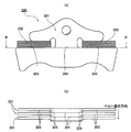
これにより、エレメント4,…のリング接触面4o,4oを後退させても、図8に示すように、エレメント4,…の中央部及び両側部に形成された当接面4j,…によって隣接するエレメント4,…を押すことができる。この結果、エレメント4,…の幅方向中央部に作用するプーリ1,2からの伝達応力を上述の第二比較例の場合よりも小さくすることができ、エレメント4,…の変形や破損を防止して、当該エレメント4の耐久性を高めることができる。
[エレメント汎用化作用]
実施例1のベルト式無段変速機のエレメント4,…では、各サドル溝4d,4dに、凹部4h,4hに嵌合した積層リング3,3とイヤー部4c,4cとの間の寸法調整を行うスペーサリング5,5がそれぞれ挿入されている。これにより、凹部4h,4hに挿入された積層リング3,3のがたつきを抑制し、サドル溝4d,4dから積層リング3,3が脱落することを防止できる。
実施例1のベルト式無段変速機のエレメント4,…では、各サドル溝4d,4dに、凹部4h,4hに嵌合した積層リング3,3とイヤー部4c,4cとの間の寸法調整を行うスペーサリング5,5がそれぞれ挿入されている。これにより、凹部4h,4hに挿入された積層リング3,3のがたつきを抑制し、サドル溝4d,4dから積層リング3,3が脱落することを防止できる。
また、積層リング3,3のリング積層数はトルク伝達容量に応じて設定されるものであり、従来では、このリング積層数に合わせてサドル溝4d,4dの大きさを設定していた。すなわち、従来のエレメントは、無段変速機におけるトルク伝達容量に応じてエレメント4,…を個別に設計する必要があった。これに対し、実施例1のベルト式無段変速機のエレメント4,…では、積層リング3,3の積層数が変動し、最外周リングとイヤー部4c,4cの間に生じる間隙の大きさが異なる場合であっても、スペーサリング5,5の厚みを調整することで対応することができる。つまり、積層リング3,3の積層数に応じてサドル溝4d,4dの大きさを設定する必要がなくなって、リング積層数に拘らずエレメント4,…の共通化を図ることができる。このため、無段変速機用ベルトVの製造コストの増大を抑制することができる。
次に、効果を説明する。
実施例1のベルト式無段変速機のエレメント4,…にあっては、下記に列挙する効果を得ることができる。
(1) 板厚方向に多数積層し、2組のリング(積層リング)3,3により環状に固定されて無段変速機用ベルトVを形成するベルト式無段変速機のエレメント4,…において、ベルト式無段変速機のプーリ1,2の溝部に挟まれ、両側のフランク部(フランク面)4k,4kでプーリ1,2からの押し付け力を支えるボディ部4aと、該ボディ部4aの幅方向中央部から延在し、前記ボディ部4aと前記ボディ部4aの幅方向に延びるイヤー部4cを連結するネック部4bと、該ネック部4bの両側に形成され、前記ボディ部4aの両側方にそれぞれ開放して前記一対のリング3,3がそれぞれ挿入される一対のサドル溝4d,4dと、を有し、前記ボディ部4aは、前記各サドル溝4d,4dの内側に形成され、前記リング3,3の内周面3a,3aが接触するリング接触面4o,4oを有する一対の凹部4h,4hと、前記各サドル溝4d,4dの開放側端部に形成され、前記リング接触面4o,4oよりも前記イヤー部4c,4c側に突出する一対の凸部4i,4iと、ベルトVの回転方向の前側面4mに形成され、隣接するエレメント4,…に対してベルトVの周方向の揺動中心となるロッキングエッジ部4gと、該ロッキングエッジ部4gよりも前記イヤー部4c,4c側に形成されるとともに、前記各凸部4i,4iの前記ベルトVの回転方向の前側面4mに形成され、隣接するエレメント4,…のベルトVの進行方向の後側面4nに当接する当接面4j,…と、を有する構成とした。
このため、エレメント4,…とリング3,3の滑りを抑えて摩擦損失を低減すると共に、応力集中を防止してエレメント4,…の耐久性を向上させることができる。
実施例1のベルト式無段変速機のエレメント4,…にあっては、下記に列挙する効果を得ることができる。
(1) 板厚方向に多数積層し、2組のリング(積層リング)3,3により環状に固定されて無段変速機用ベルトVを形成するベルト式無段変速機のエレメント4,…において、ベルト式無段変速機のプーリ1,2の溝部に挟まれ、両側のフランク部(フランク面)4k,4kでプーリ1,2からの押し付け力を支えるボディ部4aと、該ボディ部4aの幅方向中央部から延在し、前記ボディ部4aと前記ボディ部4aの幅方向に延びるイヤー部4cを連結するネック部4bと、該ネック部4bの両側に形成され、前記ボディ部4aの両側方にそれぞれ開放して前記一対のリング3,3がそれぞれ挿入される一対のサドル溝4d,4dと、を有し、前記ボディ部4aは、前記各サドル溝4d,4dの内側に形成され、前記リング3,3の内周面3a,3aが接触するリング接触面4o,4oを有する一対の凹部4h,4hと、前記各サドル溝4d,4dの開放側端部に形成され、前記リング接触面4o,4oよりも前記イヤー部4c,4c側に突出する一対の凸部4i,4iと、ベルトVの回転方向の前側面4mに形成され、隣接するエレメント4,…に対してベルトVの周方向の揺動中心となるロッキングエッジ部4gと、該ロッキングエッジ部4gよりも前記イヤー部4c,4c側に形成されるとともに、前記各凸部4i,4iの前記ベルトVの回転方向の前側面4mに形成され、隣接するエレメント4,…のベルトVの進行方向の後側面4nに当接する当接面4j,…と、を有する構成とした。
このため、エレメント4,…とリング3,3の滑りを抑えて摩擦損失を低減すると共に、応力集中を防止してエレメント4,…の耐久性を向上させることができる。
(2)前記各サドル溝4d,4dには、前記凹部4h,4hに嵌合した前記リング3,3の外周面と前記イヤー部4c,4cとの間にスペーサ(スペーサリング)5,5が挿入される構成とした。
このため、積層リング3,3の積層数を変更してもエレメント4,…を変更する必要がなくなり、コストダウンを図ることができる。
このため、積層リング3,3の積層数を変更してもエレメント4,…を変更する必要がなくなり、コストダウンを図ることができる。
(3)前記一対の凹部4h,4hのリング接触面4o,4oと前記ロッキングエッジ部4gは、前記エレメント4,…の高さ方向において、同じレベルに設ける構成とした。
このため、積層リング3,3とエレメント4,…の間のオフセット量をゼロにすることができ、摩擦損失のさらなる低下を図ることができる。
このため、積層リング3,3とエレメント4,…の間のオフセット量をゼロにすることができ、摩擦損失のさらなる低下を図ることができる。
(4)ベルト式無段変速機の入力側プーリ1と出力側プーリ2の間に掛け渡されてトルクを伝達するベルト式無段変速機のベルトVにおいて、前記入力側プーリ1と前記出力側プーリ2の溝部で挟持されるエレメント4,…と、前記エレメント4,…を積層した状態で環状に固定すると共に、前記エレメント4,…に作用するプーリ1,2の外径方向の力を支える一対のリング(積層リング)3,3と、前記エレメント4,…と前記リング3,3の間に挿入される環状のスペーサ(スペーサリング)5,5と、を有し、前記エレメント4,…は、前記入力側プーリ1と前記出力側プーリ2の溝部で挟まれ、両側のフランク部(フランク面)4k,4kでプーリ1,2からの押し付け力を支えるボディ部4aと、該ボディ部4aの幅方向中央部から延在し、前記ボディ部4aと前記ボディ部4aの幅方向に延びるイヤー部4c,4cとを連結するネック部4bと、該ネック部4bの両側に形成され、前記ボディ部4aの両側方にそれぞれ開放して前記一対のリング3,3がそれぞれ挿入される一対のサドル溝4d,4dと、を有し、前記ボディ部4aは、ベルトVの回転方向の前側面4mに形成され、隣接するエレメント4,…に対してベルトVの周方向の揺動中心となるロッキングエッジ部4gと、前記各サドル溝4d,4dの内側に形成され、前記リング3,3の内周面3a,3aが接触するリング接触面4o,4oを有する一対の凹部4h,4hと、前記各サドル溝4d,4dの開放側端部に形成され、前記リング接触面4o,4oよりも前記イヤー部4c,4c側に突出した一対の凸部4i,4iと、前記ロッキングエッジ部4gよりも前記イヤー部4c,4c側に形成されるとともに、前記各凸部4i,4iの前記ベルトVの回転方向の前側面4mに形成され、隣接するエレメント4,…のベルトVの回転方向の後側面4nに当接する当接面4j,…と、を有し、前記スペーサ5,5は、前記リング3,3の外周面と前記イヤー部4c,4cとの間に挿入される構成とした。
このため、エレメント4,…とリング3,3の滑りを抑えて摩擦損失を低減すると共に、応力集中を防止してエレメント4,…の耐久性を向上させることができる。
このため、エレメント4,…とリング3,3の滑りを抑えて摩擦損失を低減すると共に、応力集中を防止してエレメント4,…の耐久性を向上させることができる。
以上、本発明のベルト式無段変速機のエレメント及びベルトを実施例1に基づき説明してきたが、具体的な構成については、この実施例に限られるものではなく、特許請求の範囲の各請求項に係る発明の要旨を逸脱しない限り、設計の変更や追加等は許容される。
実施例1では、スペーサリング5,5の外側面5a,5aがプーリ1,2の各シーブ面11a,12a,21a,22aに接触することで、自身のサドル溝4d,4dからの脱落を防止しているが、これに限らない。
図9に示すスペーサリング6,6のように、外側面6aが各シーブ面11a,12a,21a,22aに接触しないように、凹部4h,4hに対応する長さに設定されていても良い。この場合、スペーサリング6,6がサドル溝4d,4dから脱落しないように、内側端部にイヤー部4c,4cの内側のへこみ部4c’,4c’に引っ掛かる凸部7,7を設けている。なお、この場合であっても、スペーサリング6,6とエレメント4,…との間には一定の隙間を設けることで、摩擦損失の増大を防止する。
実施例1では、エンジン車のベルト式無段変速機に適用されるベルトを構成するエレメントの例を示したが、本発明は、ハイブリッドや電気自動車等の他の車両に搭載されるベルト式無段変速機に適用されるベルトを構成するエレメントに対しても適用することができる。
V…無段変速機用ベルト
1…入力側プーリ
11a,12a…シーブ面
2…出力側プーリ
21a,22a…シーブ面
3…積層リング(リング)
3a…内周面
4…エレメント
4a…ボディ部
4b…ネック部
4c…イヤー部
4d…サドル溝
4e…ノーズ部
4f…ホール部
4g…ロッキングエッジ部
4h…凹部
4i…凸部
4j…当接面
4k…フランク面(フランク部)
4m…前側面
4n…後側面
4o…リング接触面
5…スペーサリング(スペーサ)
1…入力側プーリ
11a,12a…シーブ面
2…出力側プーリ
21a,22a…シーブ面
3…積層リング(リング)
3a…内周面
4…エレメント
4a…ボディ部
4b…ネック部
4c…イヤー部
4d…サドル溝
4e…ノーズ部
4f…ホール部
4g…ロッキングエッジ部
4h…凹部
4i…凸部
4j…当接面
4k…フランク面(フランク部)
4m…前側面
4n…後側面
4o…リング接触面
5…スペーサリング(スペーサ)
Claims (4)
- 板厚方向に多数積層し、2組のリングにより環状に固定されて無段変速機用ベルトを形成するベルト式無段変速機のエレメントにおいて、
前記ベルト式無段変速機のプーリの溝部に挟まれ、両側のフランク部でプーリ押し付け力を支えるボディ部と、
前記ボディ部の幅方向中央部から延在され、前記ボディ部と前記ボディ部の幅方向に延びるイヤー部を連結するネック部と、
前記ネック部の両側に形成され、前記ボディ部の両側方にそれぞれ開放して前記一対のリングがそれぞれ挿入される一対のサドル溝と、を有し、
前記ボディ部は、
前記各サドル溝の内側に形成され、前記リングの内周面が接触するリング接触面を有する一対の凹部と、
前記各サドル溝の開放側端部に形成され、前記リング接触面よりも前記イヤー部側に突出する一対の凸部と、
ベルト回転方向の前側の面に形成され、隣接するエレメントに対して、ベルト周方向の揺動中心となるロッキングエッジ部と、
前記ロッキングエッジ部よりも前記イヤー部側に形成されるとともに、前記各凸部の前記ベルト回転方向の前側の面に形成され、隣接するエレメントのベルト進行方向の後側の面に当接する当接面と、
を有することを特徴とするベルト式無段変速機のエレメント。 - 請求項1に記載されたベルト式無段変速機のエレメントにおいて、
前記各サドル溝には、前記凹部に嵌合した前記リングの外周面と前記イヤー部との間にスペーサが挿入されたことを特徴とするベルト式無段変速機のエレメント。 - 請求項1又は請求項2に記載された無段変速機のエレメントにおいて、
前記一対の凹部のリング接触面と前記ロッキングエッジ部は、前記エレメントの高さ方向において、同じレベルに設けたことを特徴とするベルト式無段変速機のエレメント。 - ベルト式無段変速機の入力側プーリと出力側プーリの間に掛け渡されてトルクを伝達するベルト式無段変速機のベルトにおいて、
前記プーリの溝部で挟持されるエレメントと、
前記エレメントを積層した状態で環状に固定すると共に、前記エレメントに作用するプーリ外径方向の力を支える一対のリングと、
前記エレメントと前記リングの間に挿入される環状のスペーサと、を有し、
前記エレメントは、
前記プーリの溝部で挟まれ、両側のフランク部でプーリ押し付け力を支えるボディ部と、
前記ボディ部の幅方向中央部から延在し、前記ボディ部と前記ボディ部の幅方向に延びるイヤー部を連結するネック部と、
前記ネック部の両側に形成され、前記ボディ部の両側方にそれぞれ開放して前記一対のリングがそれぞれ挿入される一対のサドル溝と、を有し、
前記ボディ部は、
ベルト回転方向の前側の面に形成され、隣接するエレメントに対して、ベルト周方向の揺動中心となるロッキングエッジ部と、
前記各サドル溝の内側に形成され、前記リングの内周面が接触するリング接触面を有する一対の凹部と、
前記各サドル溝の開放側端部に形成され、前記リング接触面よりも前記イヤー部側に突出した一対の凸部と、
前記ロッキングエッジ部よりも前記イヤー部側に形成されるとともに、前記各凸部の前記ベルト回転方向の前側の面に形成され、隣接するエレメントのベルト回転方向の後側の面に当接する当接面と、
を有し、
前記スペーサは、前記リングの外周面と前記イヤー部の間に挿入されることを特徴とするベルト式無段変速機のベルト。
Applications Claiming Priority (2)
| Application Number | Priority Date | Filing Date | Title |
|---|---|---|---|
| JP2011-070064 | 2011-03-28 | ||
| JP2011070064A JP2014141976A (ja) | 2011-03-28 | 2011-03-28 | ベルト式無段変速機のエレメントとベルト |
Publications (1)
| Publication Number | Publication Date |
|---|---|
| WO2012132794A1 true WO2012132794A1 (ja) | 2012-10-04 |
Family
ID=46930540
Family Applications (1)
| Application Number | Title | Priority Date | Filing Date |
|---|---|---|---|
| PCT/JP2012/055740 Ceased WO2012132794A1 (ja) | 2011-03-28 | 2012-03-07 | ベルト式無段変速機のエレメント及びベルト |
Country Status (2)
| Country | Link |
|---|---|
| JP (1) | JP2014141976A (ja) |
| WO (1) | WO2012132794A1 (ja) |
Cited By (1)
| Publication number | Priority date | Publication date | Assignee | Title |
|---|---|---|---|---|
| CN107110294A (zh) * | 2014-12-23 | 2017-08-29 | 罗伯特·博世有限公司 | 用于无级变速器的推带及设置有该推带的变速器 |
Citations (3)
| Publication number | Priority date | Publication date | Assignee | Title |
|---|---|---|---|---|
| JP2002054690A (ja) * | 2000-08-07 | 2002-02-20 | Honda Motor Co Ltd | 無段変速機用ベルト |
| JP2007187304A (ja) * | 2006-01-12 | 2007-07-26 | Hyundai Motor Co Ltd | 無段変速機のベルト及びこれを含む無段変速機 |
| JP2008303950A (ja) * | 2007-06-06 | 2008-12-18 | Toyota Motor Corp | 伝動ベルト |
-
2011
- 2011-03-28 JP JP2011070064A patent/JP2014141976A/ja not_active Withdrawn
-
2012
- 2012-03-07 WO PCT/JP2012/055740 patent/WO2012132794A1/ja not_active Ceased
Patent Citations (3)
| Publication number | Priority date | Publication date | Assignee | Title |
|---|---|---|---|---|
| JP2002054690A (ja) * | 2000-08-07 | 2002-02-20 | Honda Motor Co Ltd | 無段変速機用ベルト |
| JP2007187304A (ja) * | 2006-01-12 | 2007-07-26 | Hyundai Motor Co Ltd | 無段変速機のベルト及びこれを含む無段変速機 |
| JP2008303950A (ja) * | 2007-06-06 | 2008-12-18 | Toyota Motor Corp | 伝動ベルト |
Cited By (1)
| Publication number | Priority date | Publication date | Assignee | Title |
|---|---|---|---|---|
| CN107110294A (zh) * | 2014-12-23 | 2017-08-29 | 罗伯特·博世有限公司 | 用于无级变速器的推带及设置有该推带的变速器 |
Also Published As
| Publication number | Publication date |
|---|---|
| JP2014141976A (ja) | 2014-08-07 |
Similar Documents
| Publication | Publication Date | Title |
|---|---|---|
| WO2014196254A1 (ja) | 無段変速機用金属ベルト | |
| US7963873B2 (en) | Transmission belt | |
| CN108431452B (zh) | 传动带 | |
| JPWO2011061850A1 (ja) | 押圧式伝動ベルト | |
| WO2017200057A1 (ja) | 伝達ベルト | |
| JP4766064B2 (ja) | 無段変速機用ベルトのエレメントおよび無段変速機用ベルト | |
| JPWO2017138217A1 (ja) | 伝動ベルト | |
| JP5304917B2 (ja) | ベルト式無段変速機 | |
| JP5070900B2 (ja) | 無段変速機用ベルトおよびベルト式無段変速機 | |
| WO2012132794A1 (ja) | ベルト式無段変速機のエレメント及びベルト | |
| JP2021116914A (ja) | 無端金属ベルト | |
| JP2012167741A (ja) | 車両用ベルト式無段変速機における伝動ベルトのエレメント | |
| JP6852787B2 (ja) | 伝動ベルト用エレメントおよび伝動ベルト | |
| JP5678588B2 (ja) | 無段変速機用ベルト | |
| WO2024032445A1 (zh) | 一种复合传动系统用带轮 | |
| JP2007192254A (ja) | Cvtエレメントおよびcvtエレメントの製造方法 | |
| JP4946925B2 (ja) | 無段変速機用ベルト | |
| JP5061685B2 (ja) | 無段変速機用ベルトおよびベルト式無段変速機 | |
| JP2008185047A (ja) | ベルト式無段変速機 | |
| JP4200702B2 (ja) | 伝動用無端ベルト | |
| JP4545709B2 (ja) | 無段変速機用ベルト | |
| JP2010242946A (ja) | 伝動ベルト | |
| JP2016044726A (ja) | チェーンベルト | |
| JP3690016B2 (ja) | 無段変速機用vベルト | |
| JP2015075129A (ja) | ベルト式無段変速機のトルクカム構造 |
Legal Events
| Date | Code | Title | Description |
|---|---|---|---|
| 121 | Ep: the epo has been informed by wipo that ep was designated in this application |
Ref document number: 12765586 Country of ref document: EP Kind code of ref document: A1 |
|
| NENP | Non-entry into the national phase |
Ref country code: DE |
|
| 122 | Ep: pct application non-entry in european phase |
Ref document number: 12765586 Country of ref document: EP Kind code of ref document: A1 |
|
| NENP | Non-entry into the national phase |
Ref country code: JP |