WO2012132769A1 - 蓄電池の保護システム - Google Patents
蓄電池の保護システム Download PDFInfo
- Publication number
- WO2012132769A1 WO2012132769A1 PCT/JP2012/055536 JP2012055536W WO2012132769A1 WO 2012132769 A1 WO2012132769 A1 WO 2012132769A1 JP 2012055536 W JP2012055536 W JP 2012055536W WO 2012132769 A1 WO2012132769 A1 WO 2012132769A1
- Authority
- WO
- WIPO (PCT)
- Prior art keywords
- voltage
- storage battery
- threshold voltage
- protection threshold
- protection
- Prior art date
Links
Images

Classifications
-
- H—ELECTRICITY
- H02—GENERATION; CONVERSION OR DISTRIBUTION OF ELECTRIC POWER
- H02H—EMERGENCY PROTECTIVE CIRCUIT ARRANGEMENTS
- H02H7/00—Emergency protective circuit arrangements specially adapted for specific types of electric machines or apparatus or for sectionalised protection of cable or line systems, and effecting automatic switching in the event of an undesired change from normal working conditions
- H02H7/18—Emergency protective circuit arrangements specially adapted for specific types of electric machines or apparatus or for sectionalised protection of cable or line systems, and effecting automatic switching in the event of an undesired change from normal working conditions for batteries; for accumulators
-
- H—ELECTRICITY
- H01—ELECTRIC ELEMENTS
- H01M—PROCESSES OR MEANS, e.g. BATTERIES, FOR THE DIRECT CONVERSION OF CHEMICAL ENERGY INTO ELECTRICAL ENERGY
- H01M10/00—Secondary cells; Manufacture thereof
- H01M10/42—Methods or arrangements for servicing or maintenance of secondary cells or secondary half-cells
- H01M10/48—Accumulators combined with arrangements for measuring, testing or indicating the condition of cells, e.g. the level or density of the electrolyte
-
- H—ELECTRICITY
- H01—ELECTRIC ELEMENTS
- H01M—PROCESSES OR MEANS, e.g. BATTERIES, FOR THE DIRECT CONVERSION OF CHEMICAL ENERGY INTO ELECTRICAL ENERGY
- H01M10/00—Secondary cells; Manufacture thereof
- H01M10/42—Methods or arrangements for servicing or maintenance of secondary cells or secondary half-cells
- H01M10/44—Methods for charging or discharging
-
- H—ELECTRICITY
- H02—GENERATION; CONVERSION OR DISTRIBUTION OF ELECTRIC POWER
- H02J—CIRCUIT ARRANGEMENTS OR SYSTEMS FOR SUPPLYING OR DISTRIBUTING ELECTRIC POWER; SYSTEMS FOR STORING ELECTRIC ENERGY
- H02J9/00—Circuit arrangements for emergency or stand-by power supply, e.g. for emergency lighting
- H02J9/04—Circuit arrangements for emergency or stand-by power supply, e.g. for emergency lighting in which the distribution system is disconnected from the normal source and connected to a standby source
- H02J9/06—Circuit arrangements for emergency or stand-by power supply, e.g. for emergency lighting in which the distribution system is disconnected from the normal source and connected to a standby source with automatic change-over, e.g. UPS systems
-
- Y—GENERAL TAGGING OF NEW TECHNOLOGICAL DEVELOPMENTS; GENERAL TAGGING OF CROSS-SECTIONAL TECHNOLOGIES SPANNING OVER SEVERAL SECTIONS OF THE IPC; TECHNICAL SUBJECTS COVERED BY FORMER USPC CROSS-REFERENCE ART COLLECTIONS [XRACs] AND DIGESTS
- Y02—TECHNOLOGIES OR APPLICATIONS FOR MITIGATION OR ADAPTATION AGAINST CLIMATE CHANGE
- Y02E—REDUCTION OF GREENHOUSE GAS [GHG] EMISSIONS, RELATED TO ENERGY GENERATION, TRANSMISSION OR DISTRIBUTION
- Y02E60/00—Enabling technologies; Technologies with a potential or indirect contribution to GHG emissions mitigation
- Y02E60/10—Energy storage using batteries
Definitions
- the present invention relates to a storage battery protection system, and more particularly to a storage battery protection system that protects a storage battery from overcharge and overdischarge.
- a battery that charges a removable storage battery and uses stored power at a required place, or a battery that connects a charger to a load that incorporates the storage battery has been proposed.
- a switch circuit for connecting a charger, a storage battery, and a load is required, and a switch for charge / discharge control is provided between the power input / output line and the storage battery.
- Patent Document 1 describes that a charge / discharge switch is provided in a power storage device connected between a main power supply and a load.
- an FET is used for the charge / discharge switch, one end of which is connected to the positive electrode side of the power storage device, and the other end is connected to a connection point where the main power source and the load are connected.
- Patent Document 2 as a solar battery power supply system control circuit, when the charging voltage of the storage battery reaches an overcharge protection voltage that is a predetermined upper limit, the control unit turns off the switch to disconnect the solar battery from the storage battery. It is stated that the control unit turns off the switch and disconnects the storage battery from the load when the charging voltage reaches an overdischarge protection voltage that is a predetermined lower limit.
- JP 2008-232929 A Japanese Patent Laid-Open No. 6-324752
- the voltage of the storage battery is monitored, and when compared with the threshold voltage for protection, charging and discharging are stopped when the threshold voltage is exceeded. It is controlled.
- a CPU or the like determines whether or not the electric circuit is interrupted according to a predetermined sequence in accordance with a signal from the control circuit, and performs a software control for instructing and controlling the electric circuit interruption.
- these controls may not function normally due to a circuit failure or the like, and it has not been possible to reliably prevent overcharge or overdischarge.
- the storage battery may be overcharged or overdischarged before the storage battery control unit performs the charge / discharge stop process. .
- a threshold voltage for operating each protection function may be set.
- the effective use range of the storage battery is narrowed.
- the storage battery voltage and storage amount change greatly in the vicinity of full charge / overcharge, but in other areas the voltage change is smaller than lead storage batteries, etc. Make it difficult. This is particularly noticeable in systems that operate with a predetermined power storage amount of 50%, for example.
- An object of the present invention is to provide a storage battery protection system that can appropriately suppress overcharge and overdischarge of the storage battery. Another object is to provide a storage battery system that can appropriately grasp the operating state of the storage battery in order to prevent overcharge and overdischarge. The following means contribute to at least one of these purposes.
- the storage battery protection system outputs a first detection signal when the storage battery voltage exceeds the first protection threshold voltage for a first protection threshold voltage outside a movable voltage range predetermined for the storage battery.
- a storage battery protection system includes a first hardware control mechanism for preventing overvoltage or overdischarge, and a second software control provided on the overvoltage side or overdischarge side of the first hardware control mechanism.
- a mechanism is provided. More preferably, in the area beyond the first hardware control mechanism, the first hardware control mechanism can be diagnosed by the second software control mechanism or other software control mechanism.
- the storage battery system includes a first switch that turns on and off a current flowing from a charging power source that supplies a charging current to the storage battery, and a second switch that turns on and off a current flowing through a discharge load that consumes the discharge current from the storage battery.
- the current direction detecting means for detecting the direction of the current flowing through the storage battery, the on / off state display of the first switch, the on / off state display of the second switch, and the charge state display displayed based on the detection result of the current direction detecting means Or a discharge state display, and a display unit that displays the charge / discharge enable state and the charge / discharge execution state together.
- the first protection threshold voltage is set outside the movable voltage range of the storage battery, and the second protection threshold voltage is set further outside.
- Soft voltage detection means using a signal related to the voltage value of the storage battery is used.
- the hardware voltage detection means and the hardware protection circuit that operates in accordance with the hardware voltage detection means are relatively strong means, and it is unlikely that the lithium ion storage battery or the like is in an overcharge / overdischarge state. However, even when these means do not work for some reason, it is possible to suppress further overcharge / overdischarge by the soft voltage detection means and the soft protection circuit that operates accordingly.
- the hardware voltage detection means when the hardware voltage detection means is operating normally, it is unlikely that a further overcharge / overdischarge state will occur, and if there is a further overcharge / overdischarge state, any abnormality will occur. I can imagine being in a state. Therefore, it is possible to determine that the hardware voltage detecting means is abnormal when the soft voltage detecting means is operated or when it is detected that the soft voltage detecting means is approaching the operating state.
- a lithium ion battery is demonstrated as a storage battery which comprises an electrical storage part
- secondary batteries other than this may be sufficient.
- a nickel hydrogen battery, a nickel cadmium battery, or the like may be used.
- the reason for collecting a plurality of unit storage batteries as an aggregate is to obtain a voltage and a current to correspond to the required power of the load, so the content of the combination of unit storage batteries for configuring the storage battery and its The number and the like can be appropriately determined according to the specifications of the charge / discharge system of the power storage unit.
- solar power generation power and external commercial power will be described as a charging power source connected to the storage battery, but other power sources such as wind power generation power may be used.
- factory equipment, an electronic device, and an illuminating device are described as discharge load connected with a storage battery, this is an illustration of various loads, and power consumption loads other than these may be sufficient.
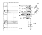
- FIG. 1 is a diagram for explaining the configuration of a storage battery protection system 10.
- the storage battery protection system 10 prevents the storage battery 40 from being overcharged or overdischarged when performing charge / discharge control between the storage battery 40, the charging power sources 12, 14, and the discharge loads 16, 17, 18. It is a system to protect.
- the charging power sources 12 and 14 include a photoelectric conversion module 12 and an external commercial power source 14.
- the photoelectric conversion module 12 is a photoelectric conversion module in which a plurality of photoelectric conversion elements are combined. The characteristics when the photoelectric conversion module is used are that the generated power value fluctuates depending on natural conditions, it is difficult to keep the supplied power value constant, and a large power fluctuation occurs in a short time.
- the external commercial power source 14 is a single-phase or three-phase AC power source, and is combined with power generated by various power generation methods such as hydroelectric power generation, nuclear power generation, and thermal power generation in accordance with fluctuations in power supply and demand. Supplied by a power company.
- the discharge loads 16, 17, and 18 show a factory facility 16, an electronic device 17 such as a personal computer, and a lighting device 18.
- Factory equipment 16 includes, in addition to mechanical equipment, factory air conditioning, kitchen appliances, factory lighting equipment, office equipment, and the like.
- the discharge loads 16, 17, and 18 include various power consuming devices that can be connected to an outlet or the like.
- a characteristic of the load-side power is that the power value varies depending on the operation status, it is difficult to set the power consumption value to a constant value, and a sudden power variation may occur.
- the storage power of the storage battery is insufficient, it is necessary to switch to power supply from commercial power. Conversely, it is necessary to switch from the supply state from the commercial power to the power supply from the storage battery. In these cases as well, large power fluctuations occur.
- the charging power supply side power converters 20A and 20B are converters such as an AC / DC converter and a DC / DC converter, and the type of converter to be used is selected according to the content of the conversion actually performed.
- the charging power supply side power converter 20A provided between the photoelectric conversion module 12 and the storage battery 40 can be omitted.
- the discharge load side power converters 22a, 22b, and 22c provided between the discharge loads 16, 17, and 18 and the switch circuit device 30 are power between the voltage of the storage battery 40 and the voltages of the discharge loads 16, 17, and 18, respectively. It has a function to perform conversion, and is a DC / DC converter or DC / AC inverter, and an appropriate one is installed according to the load. Further, the DC / DC converter can be omitted depending on the type and voltage of the load.
- the power storage unit 40 is a combination of a plurality of lithium ion battery cells.
- a storage battery pack is used in which a plurality of lithium ion battery cells are connected in series so as to have a rating of 48V, and the lithium ion battery cells are connected in parallel so as to have a rating of 1.57 kWh.
- a desired system configuration is performed by combining a plurality of the storage battery packs.
- the storage battery packs are connected in 2 series / 3 parallel.
- the switch circuit is configured so that a plurality of power storage units can be connected, and a plurality of switches corresponding to the switch 28 are connected in parallel. Therefore, three parallel storage battery packs may be connected to each switch one by one, or may be connected to one switch in three parallel states.
- the switch circuit device 30 is a circuit device including three switches 24, 26, and 28 made of elements such as FETs.
- the switches 24 and 28 have a function of performing connection or disconnection between the storage battery 40 and the charging power sources 12 and 14.
- the switches 26 and 28 have a function of connecting or blocking between the storage battery 40 and the discharge loads 16, 17 and 18. Normally, these switches 24, 26, and 28 are turned on / off under the control of the controller 50.
- the switches 24, 26 and 28 may be switch circuits such as a voltage control electronic switch and a current control type electronic switch.
- the shut-off device 70 provided between the switch circuit device 30 and the storage battery 40 shuts off the connection between the storage battery 40 and the charging power sources 12 and 14 or the connection between the storage battery 40 and the discharge loads 16, 17 and 18. Opening and closing means that can. The operation of the shut-off device 70 is performed under the control of the controller 50 except for manual opening and closing.
- the difference between the cutoff device 70 and the switch 28 included in the switch circuit device 30 is as follows. That is, the switch 28 uses a switching transistor (or FET), and can be reversibly connected and disconnected with respect to charging / discharging of the storage battery 40 by an electric signal by an on / off operation of the switching transistor.
- the shut-off device 70 is a breaker that opens and closes by electromagnetic force, and is normally in a connected state, and is shut off in an emergency or the like. Once the interruption is performed, the return is performed manually, and in this sense, it is an electrically irreversible opening / closing means.
- the shunt resistor 72 disposed in series between the switch circuit device 30 and the shut-off device 70 is a current detection resistor element that detects the magnitude and direction of the charge / discharge current flowing through the storage battery 40.
- it has a function as current direction detection means for distinguishing whether the current flowing through the storage battery 40 is a charging current or a discharging current in the direction in which the current flows.
- the display device 74 is a display panel that displays an on / off state display 76 of the three switches 24, 26, and 28 included in the switch circuit device 30 and an operation state display 78 of the storage battery 40 by lighting the lamp.
- the three switches 24, 26, and 28 are set as SW1, SW2, and SW3, respectively, and the on / off state is displayed by turning on the lamp when turned on and turning off the lamp when turned off.
- the shunt resistor 72 when the charging current flows through the storage battery 40, the charging lamp is turned on, and when the discharging current flows, the discharging lamp is turned on. When no current flows through the storage battery 40, both the charging lamp and the discharging lamp are turned off.
- the on / off state display 76 of the three switches can know whether the storage battery 40 can be charged, discharged, charged / discharged, or not charged / discharged. That is, when SW3 indicating ON / OFF of the switch 28 is lit, SW1 indicating ON / OFF of the switch 24 is lit, and when SW2 indicating ON / OFF of the switch 26 is OFF, charging is possible. When SW3 is on, SW2 is on and when SW1 is off, discharging is possible. When SW3 is turned on and SW1 and SW2 are also turned on, charging / discharging is possible. When at least SW3 is turned off, charging / discharging is impossible.
- the display device 74 it is possible to know whether the storage battery 40 is actually being charged or discharged from the operating state display 78 of the storage battery 40 of the charging lamp and discharging lamp.
- the ON / OFF state of the three switches charging is possible if the switch 28 is ON and the switch 24 is ON. There is. For example, this is the case where the photoelectric conversion module 12 is not generating power.
- the switch 28 is on and the switch 26 is on, the battery can be discharged.
- the battery may not be discharged. For example, this is the case when the discharge loads 16, 17, 18 are not operating.
- the storage battery 40 is not necessarily charged or discharged. Depending on the power consumption state of the discharge loads 16, 17, 18, the storage battery 40 may not be charged or discharged.
- the on / off state display 76 of the three switches is displayed.
- the actual charge / discharge state including the storage battery 40 cannot be grasped sufficiently.
- the operation state display 78 of the storage battery 40 is provided, so that the actual charge / discharge state including the storage battery 40 can be grasped. Accordingly, it is possible to accurately grasp when overcharge is possible in a chargeable state, when overdischarge is possible in a dischargeable state, and it is possible to appropriately cope with these situations.
- the storage battery 40 may be displayed that all three switches are turned off, and the current may be detected in the shunt resistor 72 even though the storage battery 40 is considered to be in a charge / discharge stop state. In such a case, it can be determined that the storage battery 40 is in a charged or discharged state, that is, all or one of the three switches is damaged or is not performing a predetermined operation.
- the controller 50 has a function of controlling on / off of the switches 24, 26, and 28 included in the switch circuit device 30 in order to appropriately charge and discharge the storage battery 40. That is, when the storage battery 40 is in a predetermined voltage range, the storage battery 40 can be charged by the charging power sources 12 and 14 by turning on both the switch 24 and the switch 28. In addition, by turning on both the switch 26 and the switch 28, it is possible to supply electric power from the storage battery 40 to the discharge loads 16, 17, and 18. On the other hand, when the voltage of the storage battery 40 is outside the predetermined range, the control is performed according to a predetermined sequence such as turning off the switch 24 to stop charging, or turning off the switch 26 to stop discharging. In an emergency or the like, the shut-off device 70 is put into a shut-off state according to a predetermined sequence.
- the controller 50 controls the operations of the switch circuit device 30 and the shutoff device 70 in software according to the voltage state of the storage battery 40 and the like.
- the controller 50 has a function of monitoring the voltage state of the storage battery 40.
- FIG. 2 is a diagram for explaining the state of voltage protection by monitoring the voltage state of the storage battery 40 to prevent the storage battery 40 from being overcharged or overdischarged.
- the figure surrounded by the broken line frame conceptually shows the value of the voltage at which the voltage protection of the storage battery 40 is performed by taking the voltage of the storage battery 40 on the vertical axis.
- the upper side of the vertical axis of the voltage is the high voltage side, which is the overcharge side from the storage battery 40, and the lower side is the low voltage side, the overdischarge side from the storage battery 40.
- the voltage here is not limited to the measured voltage value itself, but may be set using an index according to the voltage. For example, since there is a correlation between the charged amount and the voltage, the charged amount may be used as an index for protecting the storage battery 40.
- the movable voltage range 44 is between V U and V L.
- the movable voltage range is a voltage range arbitrarily determined by the system designer, and is set in a range narrower than the operable voltage range of the storage battery itself in consideration of the life of the storage battery.
- Several levels of protection threshold voltages are set inside and outside the movable voltage range 44.
- the protection threshold voltage is set for overcharge protection on the high voltage side of the movable voltage range 44 and for overdischarge protection on the low voltage side. Since the contents of the overcharge protection and the overdischarge protection are substantially the same, the description will be continued below assuming that the overcharge side is representative unless otherwise specified.
- V 1 (C) set outside V U that is the upper limit of the movable voltage range 44 is the first protection threshold voltage.
- C is an abbreviation for Charge which means charging.
- D of the 1st protection threshold voltage V1 (D) similarly set to the overdischarge side is the abbreviation for Discharge which means discharge.
- the first voltage detector 61 is a voltage detection means for outputting a first detection signal when the voltage of the storage battery 40 exceeds the first protection threshold voltage for the first protection threshold voltage.
- the first voltage detector 61 is hardware voltage detection means that directly cuts off the connection between the storage battery 40 and the charging power source or the discharge load based on the voltage value of the storage battery 40.
- the first voltage detector 61 is configured by using, for example, a reset IC that operates when the storage battery voltage 40 itself or the divided voltage exceeds a predetermined value. By operating the hardware voltage detection means, the photocoupler connected to the reset IC operates, the control unit terminal of the FET constituting the switch 28 and the reference voltage unit are connected, and the FET is turned off.
- the reset IC and photocoupler elements are hardware voltage detection means.
- V 2 (C) set further outside the first protection threshold voltage V 1 (C) with respect to V U which is the upper limit of the movable voltage range 44 is a second protection threshold voltage.
- the second voltage detector 62 is a voltage detection means for outputting a second detection signal when the voltage of the storage battery 40 exceeds the second protection threshold voltage for the second protection threshold voltage.
- the second voltage detector 62 uses the voltage value of the storage battery 40 as data, processes the data with a CPU or the like, and cuts off the connection between the storage battery 40 and the charging power source or the discharge load according to the processing result.
- Soft voltage detection means In FIG. 2, in order to show this, the signal processing unit 64 related to the voltage data of the storage battery 40 is conceptually illustrated. For example, when it is determined that the storage battery voltage or the storage amount is higher than a predetermined value, the second voltage detector 62 blocks the blocking device 70.
- the first protection threshold voltage V 1 is first detected by the first voltage detector 61 which is a hardware voltage detection means. It is determined whether or not (C) has been exceeded, and when it exceeds, the first detection signal is output. Based on the first detection signal, a process for stopping charging by directly turning off the switch 28 without using the CPU is performed.
- the second voltage detector 62 which is a soft voltage means, determines whether or not the second protection threshold voltage V2 (C) has been exceeded. Is output. Based on this second detection signal, a control signal for shutting off the shut-off device 70 is issued from the controller 50, and processing for stopping charging is performed.
- the first voltage detector 61 Since the first voltage detector 61 performs hardware voltage detection, even if the voltage of the storage battery 40 instantaneously exceeds the first protection threshold voltage V 1 (C) , the first voltage detector 61 outputs a voltage detection signal and outputs a CPU or the like. Cut off the circuit directly without going through.
- the soft voltage detection by the second voltage detector 62 undergoes signal processing by the CPU. For this reason, not only the voltage value of the storage battery but also other information such as the temperature of the storage battery is taken into account, and there is an advantage that charging / discharging can be stopped and any numerical value can be defined as a threshold value, but the processing in the CPU Delays and misjudgments caused by In addition, since the voltage detection based on the clock timing of the CPU is performed, the voltage detection accuracy is a hardware voltage when the fluctuation range of the voltage value of the storage battery 40 is large and the voltage instantaneously exceeds a predetermined value. Lower than detection.
- the second voltage detector 62 can determine whether the operation of the first voltage detector 61 that performs hardware voltage detection is normal based on the detection result. That is, the second voltage detector 62 is set to output the second detection signal when the voltage of the storage battery 40 reaches the second protection threshold voltage.
- the second protection threshold voltage is higher than the first protection threshold voltage at which the first voltage detector 61 should output the first detection signal, at this time, the first voltage detector 61 is inherently A 1st detection signal is output and the charge to the storage battery 40 must be stopped. Nevertheless, the voltage of the storage battery 40 exceeding the first protection threshold voltage and reaching the second protection threshold voltage indicates that the first voltage detector 61 is not operating due to some malfunction.
- the second voltage detector 62 can make a determination by signal processing by the CPU, it can output a second detection signal and notify the user that there is a problem with the first voltage detector 61. . That is, the second voltage detector can determine whether or not the operation of the first voltage detector 61 is normal based on whether or not the voltage of the storage battery 40 has reached the second protection threshold voltage.
- the second protection threshold voltage is set.
- the hardware protection circuit may be determined to be abnormal and the software protection mechanism may be activated. In this case, since the protection mechanism operates before the second protection threshold voltage is reached, the system becomes safer.
- the soft voltage detection means can check the operation of the hardware voltage detection means. Therefore, for overcharge protection of the storage battery 40, hardware voltage detection means is provided on the low voltage side, and soft voltage detection means is provided on the higher voltage side. In the case of overdischarge protection, hardware voltage detection means is provided on the high voltage side, and soft voltage detection means is provided on the lower voltage side.
- the first voltage detector 61 turns off the switch 28 by supplying a reference voltage to the control unit terminal of the FET configuring the switch 28. Further, when the first detection signal from the first voltage detector 61 is lost, the switch 28 can be turned on again by stopping the supply of the reference voltage. From this, the interruption
- the first protection threshold voltage applied to the first voltage detector 61 that performs the reversible shut-off operation is provided on the inner side of the second protection threshold voltage. It can suppress that the certain cutoff device 70 operate
- a margin can be provided between the upper limit of the movable voltage range and the second protection threshold voltage, thereby suppressing erroneous detection.
- the life of the storage battery 40 can be extended.
- V 3 (C) set further outside the second protection threshold voltage V 2 (C) with respect to the movable voltage range 44 is a third protection threshold voltage.
- 3rd voltage detector 63 is a voltage detection means which outputs a 3rd detection signal about the 3rd protection threshold voltage, when the voltage of storage battery 40 exceeds the 3rd protection threshold voltage.
- the third voltage detector 63 uses hardware voltage detection means.
- the third detection signal is output, the charge / discharge current of the storage battery 40 is forcibly cut off by sending the detection signal directly to the cut-off device 70 without using a CPU or the like.
- the third voltage detector is composed of a reset IC and a photocoupler, and when these operate, a voltage is applied to the interrupting device 70. By applying this voltage, a current flows through a coil portion provided in the interrupting device 70, and this coil portion operates as an electromagnet, so that a switch in the interrupting device 70 operates, and the electric circuit is interrupted by the interrupting device 70.
- the interruption device 70 which is an electrically irreversible interruption means operates when the voltage of the storage battery 40 reaches the overcharge side or the overdischarge side more than the switch 28 which is reversibly turned on and off by an electric signal.
- blocking apparatus 70 is made to operate
- another hardware protection may be provided on the overcharge side or the overdischarge side rather than the third voltage detector.
- another hardware protection for example, by installing a fuse that shuts off due to overvoltage between the storage battery and the main power supply or load, or opening the safety valve using the pressure of gas generated in the storage battery, the storage battery storage function can be achieved. There is a mechanism to stop it.
- an intermediate protection threshold voltage can be set between the second protection threshold voltage and the third protection threshold voltage.
- the fourth protection threshold voltage when the fourth protection threshold voltage is set before the third protection threshold voltage and the voltage of the storage battery 40 exceeds the fourth protection threshold voltage, it is detected by a soft voltage detector. It is good also as what outputs the 4th detection signal and operates interception device 70 with the signal. That is, soft voltage protection that is determined using the second protection threshold voltage and the fourth protection threshold voltage is provided before the third protection threshold voltage.
- the second voltage detection circuit is detected by a different method from the fourth voltage detection circuit to suppress an error in software detection. For example, different circuit configurations may be used, and systems having the same configuration but different clock timings may be used.
- the protection threshold voltage may be set inside the first protection threshold voltage, and the electric circuit may be interrupted by a soft voltage detector.
- FIG. 2 shows a state in which the inner threshold voltage V 0 (C) is provided inside the movable voltage range 44, that is, on the low voltage side. It is a voltage detection means which detects that the voltage of the storage battery 40 moved from the voltage inside the inner threshold voltage toward the outer voltage and exceeded the inner threshold voltage. When the voltage of the storage battery 40 exceeds the inner threshold voltage, an inner voltage detection signal is output. Similar to the second voltage detector 62, the inner voltage detector 60 is a soft voltage detector that cuts off the connection between the storage battery 40 and the charging power source or the discharging load according to the processing result by the signal processing unit 64. However, unlike the second voltage detector 62, the switch 28 is turned off to perform reversible interruption.
- the threshold voltage in each detector can be set as follows.
- the normal use range of the storage battery 40 is set to 90% of the full charge capacity in consideration of the lifespan.
- SOC 90% corresponds to 90% of the chargeable storage capacity when 3V to 4V is defined as the movable voltage range of the storage battery 40, and corresponds to 3.9V, for example.
- the reference value of the SOC is often defined as, for example, 4% for SOC 100%, and the SOC is an index according to the voltage. is there.
- SOC 90% is adopted as a numerical value corresponding to Vo (c), and when the SOC exceeds 90%, the switch 28 is reversibly turned off by software control.
- the first voltage threshold value may be set at a voltage of 4 V or higher.
- a voltage value corresponding to SOC 100% is adopted as a numerical value corresponding to Vo (c), and a plurality of inner threshold voltages are adopted using different means such as 4V as the second Vo (c). May be.
- Vo (c) and the first voltage threshold may be the same.
- the storage battery protection system according to the present invention can be used in a storage battery charge / discharge control system.
- 10 protection system 12, 14 charging power supply (12 photoelectric conversion module, 14 external commercial power supply), 16, 17, 18 discharge load (16 factory equipment, 17 electronic equipment, 18 lighting device), 20 (20A, 20B) charging power supply Side power converter, 22 (22a, 22b, 22c) discharge load side power converter, 24, 26, 28 switch, 30 switch circuit device, 40 storage battery, 44 movable voltage range, 50 controller, 60 inner voltage detector, 61 1st voltage detector, 62 2nd voltage detector, 63 3rd voltage detector, 64 signal processing part, 70 interruption
Landscapes
- Engineering & Computer Science (AREA)
- Manufacturing & Machinery (AREA)
- Chemical & Material Sciences (AREA)
- Chemical Kinetics & Catalysis (AREA)
- Electrochemistry (AREA)
- General Chemical & Material Sciences (AREA)
- Secondary Cells (AREA)
- Charge And Discharge Circuits For Batteries Or The Like (AREA)
Abstract
蓄電池の可動電圧範囲44の外側に第1保護閾値電圧V1(C)が設定され、第1電圧検出器61は、蓄電池40の電圧が第1保護閾値電圧を超えるか否かを検出し、超えるときに第1検出信号を出力する。可動電圧範囲44に対し第1保護閾値電圧よりもさらに外側に第2保護閾値電圧V2(C)が設定され、第2電圧検出器62は、蓄電池40の電圧が第2保護閾値電圧を超えるか否かを検出し、超えるときに第2検出信号を出力する。ここで、第1電圧検出器61は、蓄電池40の電圧値そのもので動作するハード的電圧検出手段であり、第2電圧検出器62は、蓄電池40の電圧値に関係する信号を用いるソフト的電圧検出手段である。
Description
本発明は、蓄電池の保護システムに係り、特に蓄電池を過充電、過放電から保護する蓄電池の保護システムに関する。
環境問題・エネルギー問題への対応として、再生可能エネルギーおよびエネルギーの有効利用に対する要求が高まっている。太陽光発電や風力発電などの再生可能エネルギーでは発電量の変動が大きいために安定電源としては不適切であり、発電電力の平準化が望まれる。また、エネルギーの有効利用としては、電力需要の平準化を行うことなどが期待されている。これらの要求を満たすために、蓄電池を活用したシステムが検討されている。
例えば、取り外し可能な蓄電池に充電を行い必要な場所で蓄電電力を用いるものや、蓄電池を内蔵した負荷に充電器を接続するものなどが提案されている。しかし、これらは小規模なシステムが多く、電力の平準化としては不十分である。そこで、充電器と蓄電池、電力変換器とを一体化し、負荷への電力供給を可能にしたものなど中規模以上のシステムが提案されている。これらのシステムにおいては、充電器・蓄電池・負荷を接続するためのスイッチ回路が必要であり、電力入出力ラインと蓄電池との間に、充放電制御のためのスイッチが設けられる。また、これらのスイッチは蓄電池の正極側に設けることが望まれる。
例えば、特許文献1には、主電源と負荷との間に接続されている蓄電装置に充放電スイッチが設けられることが述べられている。ここでは、充放電スイッチにはFETが用いられ、その一端は蓄電装置の正極側が接続され、他端は、主電源と負荷とが接続される接続点に接続されている。
また、蓄電池は、過充電または過放電となると、特性の劣化等が生じる。また、蓄電池が過度な過充電・過放電状態に達すると、蓄電池が破損する可能性がある。特許文献2には、太陽電池電源システム制御回路として、蓄電池の充電電圧が所定の上限である過充電保護電圧に達したときに制御部が開閉器をOFFにして太陽電池を蓄電池から切り離し、蓄電池の充電電圧が所定の下限である過放電保護電圧に達したときに制御部が開閉器をオフにして蓄電池を負荷から切り離すことが述べられている。
上記のように、蓄電池を過充電、過放電から保護するために、蓄電池の電圧を監視し、保護のための閾値電圧と比較して、閾値電圧を超えるときに、充放電を停止するように制御されている。充放電を停止するためには、例えば、制御回路からの信号に伴い所定のシーケンスに従い電路遮断するか否かをCPUなどで判断し、電路遮断を指示制御するソフト的制御と、例えば、所定の電圧下で動作する素子・あるいは素子群により電路遮断装置を直接動作させるようなハード的制御などがある。しかし、回路の故障等によりこれらの制御が正常に機能しない場合があり、過充電または過放電の防止を確実に行うことはできなかった。
また、蓄電池の電圧を正確に検出することは困難であり、検出電圧が正確でないと、蓄電池の制御部が充放電停止処理をする前に、蓄電池が過充電または過放電に至ってしまうことがある。
蓄電池電圧の検出結果に誤差が含まれていることを考慮して、各保護機能を動作させる閾値電圧を設定することもあるが、この場合、蓄電池の有効利用範囲が狭くなるという課題がある。さらに、リチウムイオン蓄電池などでは蓄電池電圧と蓄電量において、満充電・過充電付近では電圧が大きく変化するが、それ以外の領域では鉛蓄電池などに比べて電圧変化量が小さいことも保護機能の設定を困難にする。特に、例えば50%など所定の蓄電量を残して運用するシステムなどでは顕著である。
この他、ソフト的制御あるいはハード的制御による保護が動作している場合には電流遮断が行われているはずであるが、何らかの不具合などにより電流が遮断できていない可能性がある。従来は、このような状況を外部から容易に判断することはできず、メンテナンスや修理時において、危険を伴う場合があった。
本発明の目的は、蓄電池の過充電と過放電を適切に抑制できる蓄電池の保護システムを提供することである。他の目的は、過充電と過放電の防止のために蓄電池の稼動状態を適切に把握することができる蓄電池システムを提供することである。以下の手段は、これらの目的の少なくとも1つに貢献する。
本発明に係る蓄電池の保護システムは、蓄電池に予め定められる可動電圧範囲の外側の第1保護閾値電圧について、蓄電池の電圧が第1保護閾値電圧を超えたときに第1検出信号を出力する第1電圧検出手段と、可動電圧範囲に対し第1保護閾値電圧よりもさらに外側の第2保護閾値電圧について、蓄電池の電圧が第2保護閾値電圧を超えたときに第2検出信号を出力する第2電圧検出手段と、を備え、第1電圧検出手段は、蓄電池の電圧値により動作するハード的電圧検出手段であり、第2電圧検出手段は、蓄電池の電圧値に関係する信号を用いるソフト的電圧検出手段であることを特徴とする。
本発明に係る蓄電池の保護システムは、過電圧あるいは過放電を防ぐ第1のハード的制御機構と、第1のハード的制御機構よりも過電圧側あるいは過放電側に設けられた第2のソフト的制御機構を設けることを特徴とする。より望ましくは、第1のハード的制御機構を超えた領域において、上記第2のソフト的制御機構あるいはその他のソフト的制御機構によって第1のハード的制御機構の故障診断を可能とする。
また、本発明に係る蓄電池システムは、蓄電池に対する充電電流を供給する充電電源から流れる電流をオンオフする第1スイッチと、蓄電池からの放電電流を消費する放電負荷に流れる電流をオンオフする第2スイッチと、蓄電池を流れる電流の向きを検出する電流方向検出手段と、第1スイッチのオンオフ状態表示と、第2スイッチのオンオフ状態表示と、電流方向検出手段の検出結果に基づいて表示される充電状態表示または放電状態表示と、を含み、充放電可能状態と充放電実施状態とを合わせて表示する表示部と、を備えることを特徴とする。
上記構成により、蓄電池の可動電圧範囲の外側に第1保護閾値電圧が設定され、その更に外側に第2保護閾値電圧が設定される。そして、蓄電池の電圧が第1保護閾値電圧を超えることを検出するには、蓄電池の電圧値そのもので動作するハード的電圧検出手段を用い、第2保護閾値電圧を超えることを検出するには、蓄電池の電圧値に関係する信号を用いるソフト的電圧検出手段を用いる。一般的にはハード的電圧検出手段およびそれに伴い動作するハード的保護回路は比較的強固な手段であり、さらにリチウムイオン蓄電池などでは過充電・過放電状態となることは考えにくい。しかし、何らかの理由によりこれらの手段が働かない場合においても、ソフト的電圧検出手段およびそれに伴い動作するソフト的保護回路により、更なる過充電・過放電となることを抑制することができる。
また、ハード的電圧検出手段が正常に動作している場合においては、更なる過充電・過放電状態となることは想定しにくく、仮に更なる過充電・過放電状態となる場合にはなんらかの異常状態であることが想像できる。そのため、ソフト的電圧検出手段が動作した場合、あるいは、ソフト的電圧検出手段が動作する状態に近づきつつあることを検知した場合において、ハード的電圧検出手段の異常と判断することが可能になる。
また、上記構成によれば、蓄電池の充放電制御のスイッチの作動状態と共に蓄電池の充放電状態も合わせて表示するので、スイッチ等における何らかの不具合により電流が遮断できていない状態の確認を外部から容易に判断することが可能になる。
以下に図面を用いて本発明に係る実施の形態につき、詳細に説明する。以下では、蓄電部を構成する蓄電池としてリチウムイオン電池を説明するが、これ以外の2次電池であってもよい。例えばニッケル水素電池、ニッケルカドミウム電池等であってもよい。蓄電池を複数の単位蓄電池を集めて集合体とするのは、負荷の必要電力に対応するための電圧と電流とを得るためであるので、蓄電池を構成するための単位蓄電池の組合せの内容とその数等は、蓄電部の充放電システムの仕様に応じ適宜なものとできる。
また、以下で、蓄電池と接続される充電電源として、太陽光発電電力と外部商用電力を説明するが、これ以外の電力源、例えば風力発電電力等であってもよい。また、蓄電池と接続される放電負荷として、工場設備、電子機器、照明装置を述べるが、これは多様な負荷の例示であって、これら以外の電力消費負荷であってもよい。
以下では、全ての図面において同様の要素には同一の符号を付し、重複する説明を省略する。また、本文中の説明においては、必要に応じそれ以前に述べた符号を用いるものとする。
図1は、蓄電池の保護システム10の構成を説明する図である。この蓄電池の保護システム10は、蓄電池40と、充電電源12,14と、放電負荷16,17,18との間の充放電制御を行う際に、蓄電池40が過充電、過放電とならないように保護するシステムである。
充電電源12,14として、光電変換モジュール12と、外部商用電源14を含む。光電変換モジュール12は、複数の光電変換素子を組み合わせた光電変換モジュールである。光電変換モジュールを用いた場合の特徴としては、自然条件によって発電電力値が変動し、供給電力値を一定値とすることが難しく、また短時間で大きな電力変動が起こることである。外部商用電源14は、単相または三相の交流電力源であり、電力需給の変動に合わせて、水力発電、原子力発電、火力発電等の様々な発電方式で発電された電力を組み合わせて、外部の電力会社から供給される。
放電負荷16,17,18は、ここでは工場設備16、パーソナルコンピュータ等の電子機器17、照明装置18が図示されている。工場設備16としては、機械設備の他、工場内空調、厨房器具、工場内照明装置、事務機器等を含む。このように、放電負荷16,17,18は、コンセント等に接続することができる多様な電力消費機器を含む。負荷側電力の特徴は、稼動状況によって電力値が変動し、消費電力値を一定値とすることが難しく、急激な電力変動が生じる可能性があることである。また、これらシステムでは蓄電池の蓄電電力が不足した場合には商用電力からの電力供給に切り替える必要がある。逆に商用電力からの供給状態から蓄電池からの電力供給に切り替える必要がある。これらの場合にも大きな電力変動が生じる。
充電電源12,14とスイッチ回路装置30との間に設けられる充電電源側電力変換器20A,20Bは、それぞれ光電変換モジュール12、外部商用電源14と蓄電池40との間の電力変換を行う。具体的には、充電電源側電力変換器20A,20Bは、AC/DCコンバータ、DC/DCコンバータ等のコンバータであり、実際に行われる変換の内容に応じて、用いられるコンバータの種類が選択される。なお、光電変換モジュール12と蓄電池40との間に設けられた充電電源側電力変換器20Aは省略することも可能である。
放電負荷16,17,18とスイッチ回路装置30との間に設けられる放電負荷側電力変換器22a,22b,22cは、蓄電池40の電圧と放電負荷16,17,18の電圧との間の電力変換を行う機能を有し、DC/DCコンバータやDC/ACインバータであり、負荷に合わせて適切なものを設置する。また、負荷の種類や電圧によってはDC/DCコンバータを省略することも可能である。
蓄電部40は、複数のリチウムイオン電池セルを組み合わせたものである。本実施例では、定格48Vとなるようにリチウムイオン電池セルを複数本直列に接続するとともに、定格1.57kWhとなるようにリチウムイオン電池セルを並列接続した蓄電池パックを用いている。上記蓄電池パックを複数組み合わせて、所望のシステム構成を行う。
一例としては、100V-9kW程度のシステム構成とする場合には、上記蓄電池パックを2直列・3並列接続する。なお、スイッチ回路には複数の蓄電部を接続可能なように構成されており、スイッチ28に相当する複数のスイッチが並列に接続されている。そのため、3並列の蓄電池パックは、それぞれのスイッチに1並列ずつ接続してもよく、3並列の状態で1つのスイッチに接続してもよい。
スイッチ回路装置30は、ここでは、FET等の素子からなる3つのスイッチ24,26,28を含む回路装置である。3つのスイッチ24,26,28の内で、スイッチ24,28は、蓄電池40と充電電源12,14との間の接続または遮断を行う機能を有する。スイッチ26,28は、蓄電池40と放電負荷16,17,18との間の接続または遮断を行う機能を有する。通常、これらのスイッチ24,26,28のオンオフは、コントローラ50の制御の下で行われる。なお、スイッチ24、26、28は電圧制御電子スイッチ、電流制御型電子スイッチなどのスイッチ回路でもよい。
スイッチ回路装置30と蓄電池40の間に設けられる遮断装置70は、蓄電池40と充電電源12,14との間の接続、あるいは蓄電池40と放電負荷16,17,18との間の接続を遮断することができる開閉手段である。遮断装置70の動作は、手動による開閉以外は、コントローラ50の制御の下で行われる。
遮断装置70と、スイッチ回路装置30に含まれるスイッチ28との間の相違は以下の通りである。すなわち、スイッチ28は、スイッチングトランジスタ(またはFET)が用いられ、スイッチングトランジスタのオンオフ動作によって、蓄電池40の充放電に関する接続と遮断を電気信号によって可逆的に行うことができる。これに対し、遮断装置70は、電磁力により開閉するブレーカーであって、通常は接続状態とされ、緊急時等に、遮断が行われる。一旦遮断が行われると、その復帰は手動で行われ、その意味で、電気的には不可逆的な開閉手段である。
スイッチ回路装置30と遮断装置70との間に直列接続されて配置されるシャント抵抗72は、蓄電池40に流れる充放電電流の大きさと方向とを検出する電流検出抵抗素子である。ここでは、特に、電流の流れる方向で、蓄電池40に流れる電流が充電電流か放電電流かを区別する電流方向検出手段としての機能を有する。
表示装置74は、スイッチ回路装置30に含まれる3つのスイッチ24,26,28のオンオフ状態表示76と、蓄電池40の稼動状態表示78とをランプの点灯によって表示する表示盤である。ここでは、3つのスイッチ24,26,28をそれぞれSW1,SW2,SW3として、オンのときはランプ点灯、オフのときはランプ消灯でそのオンオフ状態を表示する。また、シャント抵抗72の検出結果に基づき、蓄電池40に充電電流が流れるときは、充電中ランプが点灯し、放電電流が流れるときは放電中ランプを点灯する。蓄電池40に電流が流れないときは、充電中ランプも放電中ランプも消灯する。
表示装置74において、3つのスイッチのオンオフ状態表示76によって、蓄電池40の充電可能、放電可能、充放電可能、充放電不可能の状態を知ることができる。すなわち、スイッチ28のオンオフを示すSW3が点灯しているとき、さらにスイッチ24のオンオフを示すSW1が点灯して、スイッチ26のオンオフを示すSW2が消灯のときは、充電可能である。SW3が点灯しているときに、さらにSW2が点灯、SW1が消灯のときは放電可能である。SW3が点灯しているときに、さらにSW1もSW2も点灯のときは充放電可能である。少なくともSW3が消灯しているときは、充放電不可能である。
表示装置74において、充電中ランプと放電中ランプの蓄電池40の稼動状態表示78によって、蓄電池40が実際に充電中か放電中かを知ることができる。3つのスイッチのオンオフ状態において、スイッチ28がオンでスイッチ24がオンであれば充電可能であるが、その場合でも蓄電池40の充電状態や充電電源12,14の状態によっては、充電していないことがある。例えば、光電変換モジュール12が発電していない場合等である。逆にスイッチ28がオンでスイッチ26がオンであれば放電可能であるが、蓄電池40の充電状態や放電負荷16,17,18によっては、放電していないことがある。例えば、放電負荷16,17,18が稼動していない場合等である。スイッチ28がオンで、スイッチ24もスイッチ26もオンのときは充放電可能であるが、このとき蓄電池40は必ずしも充電または放電状態であるとは限らず、充電電源12,14の電力供給状態と放電負荷16,17,18の電力消費状態によっては、蓄電池40が充電も放電も行っていないことがある。
このように、充電電源12,14の供給電力値が一定でなくて変動し、放電負荷16,17,18の消費電力値が一定でなくて変動するときは、3つのスイッチのオンオフ状態表示76のみでは蓄電池40を含む充放電状態の実際の把握が十分に行えない。表示装置74では、3つのスイッチのオンオフ状態表示76に加えて、蓄電池40の稼動状態表示78が設けられるので、蓄電池40を含む実際の充放電状態を把握できる。これによって、充電可能状態で過充電のとき、放電可能状態で過放電の時などを的確に把握でき、これらの状況に適切に対応することが可能になる。
さらに、例えば、3つのスイッチが全てオフになっていると表示され、蓄電池40が充放電停止状態にあると考えられるにも関わらず、シャント抵抗72において電流が検出される場合がある。このような場合、蓄電池40は充電あるいは放電状態であり、すなわち、3つのスイッチの全てあるいはいずれかが破損している、あるいは、所定の動作をしていないと判断することができる。
コントローラ50は、蓄電池40の充放電を適切なものとするために、スイッチ回路装置30に含まれるスイッチ24,26,28のオンオフを制御する機能を有する。すなわち、蓄電池40が予め定めた電圧範囲にあるときは、スイッチ24とスイッチ28を共にオンとすることで、充電電源12,14によって蓄電池40を充電することを可能とする。また、スイッチ26とスイッチ28を共にオンとすることで、蓄電池40から放電負荷16,17,18に電力を供給することを可能とする。一方、蓄電池40の電圧が所定の範囲外にあるときには、スイッチ24をオフとし充電を停止する、あるいはスイッチ26をオフとし放電を停止するなど、所定のシーケンスに従い制御する。また、緊急時等には、所定のシーケンスに従い、遮断装置70を遮断状態にする。
このように、コントローラ50は、蓄電池40の電圧状態などに応じて、スイッチ回路装置30と遮断装置70の動作をソフト的に制御する。そのために、コントローラ50は、蓄電池40の電圧状態を監視する機能を有する。
図2は、蓄電池40の電圧状態を監視して、蓄電池40が過充電、過放電とならないようにする電圧保護の様子を説明する図である。破線枠で囲んだ図は、縦軸に蓄電池40の電圧をとって、蓄電池40の電圧保護が行われる電圧の値を概念的に示したものである。電圧の縦軸の上側の方が高電圧側で、蓄電池40からいえば過充電側であり、下側の方が低電圧側で蓄電池40からいえば過放電側である。なお、ここでいう電圧とは測定電圧値そのものだけではなく、電圧に準じる指標を用いて設定されたものでもよい。例えば、蓄電量と電圧とには相関があるため、蓄電量を蓄電池40に対する保護を行うための指標としてもよい。
電圧の縦軸において、VUとVLの間が可動電圧範囲44である。ここで可動電圧範囲とは、システム設計者が任意に定めた電圧範囲であり、蓄電池の寿命などを考慮して蓄電池自体の動作可能電圧範囲よりも狭い範囲で設定されている。この可動電圧範囲44の内側と外側に、数段階の保護閾値電圧が設定される。保護閾値電圧の設定は、可動電圧範囲44の高電圧側に過充電保護用、低電圧側に過放電保護用としてそれぞれ行われる。過充電保護用も過放電保護用も、その内容はほぼ同じであるので、以下では、特に断らない限り、過充電側に代表させることにして説明を続ける。
可動電圧範囲44の上限であるVUの外側に設定されるV1(C)は、第1保護閾値電圧である。Cは充電を意味するChargeの略である。なお、過放電側に同様に設定される第1保護閾値電圧V1(D)のDは、放電を意味するDischargeの略である。
第1電圧検出器61は、第1保護閾値電圧について、蓄電池40の電圧が第1保護閾値電圧を超えたときに第1検出信号を出力する電圧検出手段である。ここで、第1電圧検出器61は、蓄電池40の電圧値に基づき、蓄電池40と充電電源または放電負荷との接続を直接的に遮断するハード的電圧検出手段である。第1電圧検出器61は、例えば、蓄電池電圧40自体あるいは分圧された電圧が所定値を超えた場合に動作するリセットICを用いていて構成される。このハード的電圧検出手段が動作することで、リセットICに接続されたフォトカプラーが動作し、スイッチ28を構成するFETの制御部端子と基準電圧部とが接続され上記FETがオフとなる。なお、リセットICおよびフォトカプラーの素子群がハード的電圧検出手段である。
可動電圧範囲44の上限であるVUに対し、第1保護閾値電圧V1(C)よりもさらに外側に設定されるV2(C)は、第2保護閾値電圧である。
第2電圧検出器62は、第2保護閾値電圧について、蓄電池40の電圧が第2保護閾値電圧を超えたときに第2検出信号を出力する電圧検出手段である。ここで、第2電圧検出器62は、蓄電池40の電圧値をデータとして、そのデータをCPU等にて処理し、処理結果に応じて蓄電池40と、充電電源または放電負荷との接続を遮断するソフト的電圧検出手段である。図2では、そのことを示すために、蓄電池40の電圧データに関する信号処理部64が概念的に図示されている。第2電圧検出器62は、例えば、蓄電池電圧あるいは蓄電量が所定値よりも高いと判断された場合に、遮断装置70を遮断させる。
このようにすることで、蓄電池40が充電によって可動電圧範囲44よりも高電圧側に移動するときに、まず、ハード的電圧検出手段である第1電圧検出器61によって第1保護閾値電圧V1(C)を超えたか否かが判断され、超えるときに第1検出信号を出力する。この第1検出信号に基づいて、CPUを介さずに、直接スイッチ28をオフして充電を止める処理を行う。
さらに蓄電池40の電圧が上昇すると、次にソフト的電圧手段である第2電圧検出器62によって第2保護閾値電圧V2(C)を超えたか否かが判断され、超えるときに第2検出信号を出力する。この第2検出信号に基づいて、コントローラ50から遮断装置70を遮断するための制御信号が出され、充電を止める処理を行う。
第1電圧検出器61はハード的電圧検出を行うため、蓄電池40の電圧が瞬間的に第1保護閾値電圧V1(C)を超えた場合でも、電圧検出信号を出し、かつ、CPUなどを介さずに直接的に電路遮断を行う。
一方で、第2電圧検出器62によるソフト的電圧検出はCPUによる信号処理を経る。このため、蓄電池の電圧値だけでなく、蓄電池の温度等、他の情報も併せて考慮し、充放電を停止できることや、任意の数値を閾値として規定できるなどの利点がある反面、CPUにおける処理に起因する遅延や誤判断が生じ得る。また、CPUのクロックタイミングに基づいた電圧検出を行うことなどから、蓄電池40の電圧値の変動幅が大きく、電圧が瞬間的に所定値を超えた場合などにおいて、電圧検出の精度がハード的電圧検出よりも低くなる。
しかし、第2電圧検出器62は、その検出結果に基づいて、ハード的電圧検出を行う第1電圧検出器61の動作が正常か否かを判断することができる。つまり、第2電圧検出器62は、蓄電池40の電圧が第2保護閾値電圧に達したときに第2検出信号を出力するよう設定されている。ここで、第2保護閾値電圧は、第1電圧検出器61が第1検出信号を出力すべき第1保護閾値電圧よりも高い値であるため、この時点では第1電圧検出器61は本来、第1検出信号を出力し、蓄電池40への充電は停止されていなければならない。にもかかわらず、蓄電池40の電圧は第1保護閾値電圧を超えて第2保護閾値電圧に達したことは、第1電圧検出器61が何らかの不具合により動作していないことを示す。
第2電圧検出器62はCPUよる信号処理によって判断を行うことができるため、第2検出信号を出力するとともに、第1電圧検出器61に不具合が存在することを使用者に通知することができる。つまり、第2電圧検出器は蓄電池40の電圧が第2保護閾値電圧に達したか否かによって、第1電圧検出器61の動作が正常か否かを判断することができる。
また、ソフト的電圧検出手段により検出された電圧が第1保護閾値電圧を超えており、かつ第2保護閾値電圧に継続して近づきつつあると判断される場合には、第2保護閾値電圧に到達する前に、ハード的保護回路が異常であると判断し、ソフト的保護機構を動作させてもよい。この場合、第2保護閾値電圧になる前に保護機構が動作するのでより安全なシステムとなる。
このほか、蓄電池40の充放電電流値に限らず、第1電圧検出器61の動作状況を示す様々な信号によって、制御部に第1電圧検出器61の動作が正常であるか否かを判断させることができる。例えば、第1電圧検出器61から第1電圧検出器61自体の動作状況を示す信号を制御部に対して出力させてもよい。このように、ソフト的電圧検出手段はハード的電圧検出手段の動作チェックが可能である。そこで、蓄電池40の過充電保護のためには、低電圧側にハード的電圧検出手段を設け、それより高電圧側にソフト的電圧検出手段を設ける。なお、過放電保護の場合には、高電圧側にハード的電圧検出手段を設け、それより低電圧側にソフト的電圧検出手段を設ける。
また本構成において、第1電圧検出器61は、スイッチ28を構成するFETの制御部端子に基準電圧を供給することによりスイッチ28をオフする。また、第1電圧検出器61からの第1検出信号がなくなった場合などに、基準電圧の供給を止めることでスイッチ28を再びオンすることができる。このことから、第1電圧検出器61の遮断動作は可逆的であり、異常状態が解消されれば蓄電池40は充放電動作に復帰できる。
上述のとおり、蓄電池40の電圧変動が大きい場合、第2電圧検出器62による電圧検出の精度は低くなる。そのため、可逆的な遮断動作を行う第1電圧検出器61にかかる第1保護閾値電圧を、第2保護閾値電圧よりも内側に設けることで、第2検出信号の誤検出によって不可逆的な遮断である遮断装置70が動作することを抑制できる。
特に、可動電圧範囲を蓄電池40自体の動作可能範囲の内側に規定したシステムにおいては、可動電圧範囲の上限と第2保護閾値電圧との間に余裕を設けることができ、誤検出を抑制することができるとともに、蓄電池40の寿命を延ばすことができる。
可動電圧範囲44に対し第2保護閾値電圧V2(C)よりもさらに外側に設定されるV3(C)は、第3保護閾値電圧である。
第3電圧検出器63は、第3保護閾値電圧について、蓄電池40の電圧が第3保護閾値電圧を超えたときに第3検出信号を出力する電圧検出手段である。ここで、第3電圧検出器63は、第1電圧検出器61と同様に、ハード的電圧検出手段が用いられる。第3検出信号が出力されると、その検出信号を、CPUなどを介さずに直接遮断装置70に送ることよって蓄電池40の充放電電流が強制的に遮断される。例えば、第3電圧検出器はリセットICとフォトカプラーで構成されており、これらが動作することで、遮断装置70に対して電圧が印加されるようになる。この電圧印加により、遮断装置70内に設けたコイル部分に電流が流れ、このコイル部分が電磁石として動作することで遮断装置70内のスイッチが動作し、遮断装置70による電路遮断を行う。
このように、電気的に不可逆的遮断手段である遮断装置70は、電気信号で可逆的にオンオフするスイッチ28に比べて、蓄電池40の電圧がより過充電側あるいは過放電側に達した時に動作するようにしている。なお、遮断装置70の動作は第2電圧検出器と第3電圧検出器のいずれかにより動作するようにしているが、例えば第3電圧検出器による動作は省略してもよい。この場合、第3電圧検出器により動作する別のハード保護を設けてもよい。また、逆に第3電圧検出器による遮断装置70の制御を設けたうえで、それに加えて、別のハード保護を第3電圧検出器よりも過充電側あるいは過放電側に設けてもよい。別のハード保護としては、例えば、蓄電池と主電源または負荷の間に過電圧で遮断するヒューズの設置や、蓄電池内で発生したガスの圧力を利用して安全弁を開放することで蓄電池の蓄電機能を停止させる機構などがある。
また、第2保護閾値電圧と第3保護閾値電圧との間に、中間的保護閾値電圧を設定することができる。例えば、第3保護閾値電圧の手前に、第4保護閾値電圧を設定し、蓄電池40の電圧がこの第4保護閾値電圧を超えるか否かをソフト的電圧検出器で検出して、超えるときに第4検出信号を出力し、その信号で遮断装置70を作動させるものとしてもよい。すなわち、第3保護閾値電圧の手前に第2保護閾値電圧と第4保護閾値電圧を用いて判断するソフト的電圧保護を設ける。この際に、第2電圧検出回路を第4電圧検出回路は異なる手法で検出するようにし、ソフト的検出の誤差を抑制するようにすることが望ましい。例えば、異なる回路構成としてもよく、同一の構成ではあるがクロックタイミングの異なる方式としてもよい。
さらに、第1保護閾値電圧の内側に保護閾値電圧を設定し、ソフト的電圧検出器にて電路遮断を行ってもよい。図2では、可動電圧範囲44の内側、すなわち低電圧側に、内側閾値電圧V0(C)が設けられる様子が示される。蓄電池40の電圧がこの内側閾値電圧よりも内側の電圧から外側の電圧に向けて移動して内側閾値電圧を超えたことを検出する電圧検出手段である。蓄電池40の電圧が内側閾値電圧を超えたときに、内側電圧検出信号が出力される。内側電圧検出器60は、第2電圧検出器62と同様に、信号処理部64による処理結果に応じて、蓄電池40と、充電電源または放電負荷との接続を遮断するソフト的電圧検出器であるが、第2電圧検出器62とは異なり、スイッチ28をOFFするなど、可逆的な遮断を行う。
また、各検出器における閾値電圧は以下のように設定することが考えられる。例えば、動作可能電圧の上限が4.2Vである蓄電池40の可動電圧範囲の上限を4Vまでとしたシステムにおいて、寿命などを考慮して、蓄電池40の通常使用範囲を満充電容量の90%(以下ではSOC90%と表現する)までとしてもよい。なお、SOC90%とは、3V~4Vを蓄電池40の可動電圧範囲と規定した場合に、充電可能な蓄電容量の90%に相当するものであり、例えば3.9Vに相当する。なお、SOCの算出方法として充放電電流量から換算する手段などがあるが、SOCの基準となる数値は、例えばSOC100%は4Vとすると規定していることが多く、SOCは電圧に準じる指標である。
そこで、Vo(c)に相当する数値としてSOC90%を採用し、SOC90%を超えたらソフト的制御によりスイッチ28を可逆的にオフにする。そして4Vあるいはそれ以上の電圧において、第1電圧閾値を設定してもよい。また、Vo(c)に相当する数値としてSOC100%に相当する電圧値を採用し、さらに第2のVo(c)として4Vを採用するなど、異なる手段を用いて、複数の内側閾値電圧を採用してもよい。さらに、Vo(c)と第1電圧閾値を同一としてもよい。
本発明に係る蓄電池の保護システムは、蓄電池の充放電制御システムに利用することができる。
10 保護システム、12,14 充電電源(12 光電変換モジュール、14 外部商用電源)、16,17,18 放電負荷(16 工場設備、17 電子機器、18 照明装置)、20(20A,20B) 充電電源側電力変換器、22(22a,22b,22c) 放電負荷側電力変換器、24,26,28 スイッチ、30 スイッチ回路装置、40 蓄電池、44 可動電圧範囲、50 コントローラ、60 内側電圧検出器、61 第1電圧検出器、62 第2電圧検出器、63 第3電圧検出器、64 信号処理部、70 遮断装置、72 シャント抵抗、74 表示装置、76 オンオフ状態表示、78 稼動状態表示。
Claims (5)
- 蓄電池に予め定められる可動電圧範囲の外側の第1保護閾値電圧について、前記蓄電池の電圧が前記第1保護閾値電圧を超えたときに第1検出信号を出力する第1電圧検出手段と、
前記可動電圧範囲に対し前記第1保護閾値電圧よりもさらに外側の第2保護閾値電圧について、前記蓄電池の電圧が第2保護閾値電圧を超えたときに第2検出信号を出力する第2電圧検出手段と、
を備え、
前記第1電圧検出手段は、前記蓄電池の電圧値によって動作するハード的電圧検出手段であり、
前記第2電圧検出手段は、前記蓄電池の電圧値に関係する信号を用いるソフト的電圧検出手段であることを特徴とする蓄電池の保護システム。 - 請求項1に記載の蓄電池の保護システムにおいて、
前記第2電圧検出手段である前記ソフト的電圧検出手段の検出結果に基づいて、前記第1電圧検出手段である前記ハード的電圧検出手段の動作が正常か否かを判断する判断手段を備えることを特徴とする蓄電池の保護システム。 - 請求項2に記載の蓄電池の保護システムにおいて、
前記蓄電池の充放電について、可逆的なオンオフを行うことができるオンオフ手段と、
前記第2保護閾値電圧を超えたことを検出する信号に基づいて、前記オンオフ手段を作動させて前記蓄電池の充放電を停止させるオンオフ手段作動手段と、
前記可動電圧範囲に対し前記第2保護閾値電圧よりもさらに外側の第3保護閾値電圧について、前記蓄電池の電圧が前記第3保護閾値電圧を超えたときに第3検出信号を出力する電圧検出手段と、
前記蓄電池の充放電について、不可逆的な遮断を行うことができる遮断手段と、
前記第3保護閾値電圧を超えたことを検出する信号に基づいて、前記遮断手段を作動させて前記蓄電池の充放電を停止させる遮断手段作動手段と、
を備えることを特徴とする蓄電池の保護システム。 - 請求項1乃至3のいずれか1に記載の蓄電池の保護システムにおいて、
前記蓄電池の前記可動範囲の内側に設定される内側閾値電圧について、前記蓄電池の電圧が前記内側閾値電圧よりも内側の電圧から外側の電圧に向けて移動して前記内側閾値電圧を超えたときに、内側電圧検出信号を出力する内側電圧検出手段を備えることを特徴とする蓄電池の保護システム。 - 蓄電池に対する充電電流を供給する充電電源に流れる電流をオンオフする第1スイッチと、
前記蓄電池からの放電電流を消費する放電負荷に流れる電流をオンオフする第2スイッチと、
前記蓄電池を流れる電流の向きを検出する電流方向検出手段と、
前記第1スイッチのオンオフ状態表示と、前記第2スイッチのオンオフ状態表示と、前記電流方向検出手段の検出結果に基づいて表示される充電状態表示または放電状態表示と、を含み、充放電可能状態と充放電実施状態とを合わせて表示する表示部と、
を備えることを特徴とする蓄電池の保護システム。
Applications Claiming Priority (2)
| Application Number | Priority Date | Filing Date | Title |
|---|---|---|---|
| JP2011-080920 | 2011-03-31 | ||
| JP2011080920 | 2011-03-31 |
Publications (1)
| Publication Number | Publication Date |
|---|---|
| WO2012132769A1 true WO2012132769A1 (ja) | 2012-10-04 |
Family
ID=46930516
Family Applications (1)
| Application Number | Title | Priority Date | Filing Date |
|---|---|---|---|
| PCT/JP2012/055536 WO2012132769A1 (ja) | 2011-03-31 | 2012-03-05 | 蓄電池の保護システム |
Country Status (1)
| Country | Link |
|---|---|
| WO (1) | WO2012132769A1 (ja) |
Cited By (4)
| Publication number | Priority date | Publication date | Assignee | Title |
|---|---|---|---|---|
| JP2017208344A (ja) * | 2016-05-20 | 2017-11-24 | ドクター エンジニール ハー ツェー エフ ポルシェ アクチエンゲゼルシャフトDr. Ing. h.c. F. Porsche Aktiengesellschaft | 自動車用のエネルギー貯蔵ユニット、およびエネルギー貯蔵ユニットを取り付けるための方法 |
| CN112271765A (zh) * | 2020-09-28 | 2021-01-26 | 北京空间飞行器总体设计部 | 一种用于航天器的锂离子蓄电池组过充电保护方法 |
| CN113504495A (zh) * | 2021-07-07 | 2021-10-15 | 广西桂能科技发展有限公司 | 便携式蓄电池充放电测试仪的检测装置及检测方法 |
| WO2024057494A1 (ja) * | 2022-09-15 | 2024-03-21 | 日本電信電話株式会社 | 光給電装置及び接続切替方法 |
Citations (2)
| Publication number | Priority date | Publication date | Assignee | Title |
|---|---|---|---|---|
| JP2004265000A (ja) * | 2003-02-28 | 2004-09-24 | Toshiba Corp | 電子機器および同機器の給電設定方法 |
| JP2008245400A (ja) * | 2007-03-27 | 2008-10-09 | Matsushita Electric Ind Co Ltd | 電池パック |
-
2012
- 2012-03-05 WO PCT/JP2012/055536 patent/WO2012132769A1/ja active Application Filing
Patent Citations (2)
| Publication number | Priority date | Publication date | Assignee | Title |
|---|---|---|---|---|
| JP2004265000A (ja) * | 2003-02-28 | 2004-09-24 | Toshiba Corp | 電子機器および同機器の給電設定方法 |
| JP2008245400A (ja) * | 2007-03-27 | 2008-10-09 | Matsushita Electric Ind Co Ltd | 電池パック |
Cited By (5)
| Publication number | Priority date | Publication date | Assignee | Title |
|---|---|---|---|---|
| JP2017208344A (ja) * | 2016-05-20 | 2017-11-24 | ドクター エンジニール ハー ツェー エフ ポルシェ アクチエンゲゼルシャフトDr. Ing. h.c. F. Porsche Aktiengesellschaft | 自動車用のエネルギー貯蔵ユニット、およびエネルギー貯蔵ユニットを取り付けるための方法 |
| US11217834B2 (en) | 2016-05-20 | 2022-01-04 | Dr. Ing. H.C. F. Porsche Aktiengesellschaft | Energy storage unit for a motor vehicle battery, and method for fitting an energy storage unit |
| CN112271765A (zh) * | 2020-09-28 | 2021-01-26 | 北京空间飞行器总体设计部 | 一种用于航天器的锂离子蓄电池组过充电保护方法 |
| CN113504495A (zh) * | 2021-07-07 | 2021-10-15 | 广西桂能科技发展有限公司 | 便携式蓄电池充放电测试仪的检测装置及检测方法 |
| WO2024057494A1 (ja) * | 2022-09-15 | 2024-03-21 | 日本電信電話株式会社 | 光給電装置及び接続切替方法 |
Similar Documents
| Publication | Publication Date | Title |
|---|---|---|
| US9112247B2 (en) | Battery system | |
| JP5449334B2 (ja) | 制御装置および制御方法 | |
| KR101344566B1 (ko) | 축전 시스템 | |
| WO2012050210A1 (ja) | 蓄電システム及び制御装置 | |
| WO2012050032A1 (ja) | 電源システム | |
| EP2557653A1 (en) | Self-diagnostic device for power storage system | |
| JP2004215459A (ja) | 電源制御装置 | |
| US10177586B2 (en) | Electric energy storage apparatus | |
| CN102570531B (zh) | 多级充电均衡控制装置及方法 | |
| JP6288722B2 (ja) | 電池システム | |
| JP2012175864A (ja) | 蓄電システム | |
| JP5361594B2 (ja) | リチウムイオン二次電池システムおよび管理装置への電力供給方法 | |
| WO2012132769A1 (ja) | 蓄電池の保護システム | |
| JP2006223050A (ja) | 電力供給システム | |
| EP2782201B1 (en) | Storage battery unit | |
| EP3654480B1 (en) | Power conditioner, power system, and reactive power supressing method for power system | |
| JP5858236B2 (ja) | 蓄電池システム | |
| KR101782223B1 (ko) | 배터리 조절 시스템 진단 장치 및 이를 포함하는 에너지 저장 시스템 | |
| KR20190093405A (ko) | 리튬 이온 배터리 호환 배터리 컨트롤 장치 및 그 제어 방법 | |
| JP5448564B2 (ja) | リチウムイオン組電池の管理装置および管理方法 | |
| JP2014055902A (ja) | 原子力発電プラント用直流電源設備 | |
| JP2013074715A (ja) | 充電装置 | |
| JPWO2013136413A1 (ja) | 電力蓄積システム、および、蓄電モジュールの制御方法 | |
| KR100982560B1 (ko) | 개폐기용 배터리유닛 | |
| KR20210085713A (ko) | 셀프 에너지 밸런싱을 고려한 배터리 관리 시스템 및 이를 이용한 배터리 관리방법 |
Legal Events
| Date | Code | Title | Description |
|---|---|---|---|
| 121 | Ep: the epo has been informed by wipo that ep was designated in this application |
Ref document number: 12763296 Country of ref document: EP Kind code of ref document: A1 |
|
| NENP | Non-entry into the national phase |
Ref country code: DE |
|
| 122 | Ep: pct application non-entry in european phase |
Ref document number: 12763296 Country of ref document: EP Kind code of ref document: A1 |
|
| NENP | Non-entry into the national phase |
Ref country code: JP |