WO2012132544A1 - ワイヤハーネス用のバンドクリップ - Google Patents
ワイヤハーネス用のバンドクリップ Download PDFInfo
- Publication number
- WO2012132544A1 WO2012132544A1 PCT/JP2012/052415 JP2012052415W WO2012132544A1 WO 2012132544 A1 WO2012132544 A1 WO 2012132544A1 JP 2012052415 W JP2012052415 W JP 2012052415W WO 2012132544 A1 WO2012132544 A1 WO 2012132544A1
- Authority
- WO
- WIPO (PCT)
- Prior art keywords
- blade
- wire harness
- clip
- section
- sections
- Prior art date
- Legal status (The legal status is an assumption and is not a legal conclusion. Google has not performed a legal analysis and makes no representation as to the accuracy of the status listed.)
- Ceased
Links
Images






Classifications
-
- B—PERFORMING OPERATIONS; TRANSPORTING
- B65—CONVEYING; PACKING; STORING; HANDLING THIN OR FILAMENTARY MATERIAL
- B65D—CONTAINERS FOR STORAGE OR TRANSPORT OF ARTICLES OR MATERIALS, e.g. BAGS, BARRELS, BOTTLES, BOXES, CANS, CARTONS, CRATES, DRUMS, JARS, TANKS, HOPPERS, FORWARDING CONTAINERS; ACCESSORIES, CLOSURES, OR FITTINGS THEREFOR; PACKAGING ELEMENTS; PACKAGES
- B65D63/00—Flexible elongated elements, e.g. straps, for bundling or supporting articles
- B65D63/10—Non-metallic straps, tapes, or bands; Filamentary elements, e.g. strings, threads or wires; Joints between ends thereof
- B65D63/1018—Joints produced by application of integral securing members, e.g. buckles, wedges, tongue and slot, locking head and teeth or the like
- B65D63/1027—Joints produced by application of integral securing members, e.g. buckles, wedges, tongue and slot, locking head and teeth or the like the integral securing member being formed as a female and male locking member, e.g. locking head and locking teeth, or the like
- B65D63/1063—Joints produced by application of integral securing members, e.g. buckles, wedges, tongue and slot, locking head and teeth or the like the integral securing member being formed as a female and male locking member, e.g. locking head and locking teeth, or the like the female locking member being provided with at least one plastic barb
-
- B—PERFORMING OPERATIONS; TRANSPORTING
- B60—VEHICLES IN GENERAL
- B60R—VEHICLES, VEHICLE FITTINGS, OR VEHICLE PARTS, NOT OTHERWISE PROVIDED FOR
- B60R16/00—Electric or fluid circuits specially adapted for vehicles and not otherwise provided for; Arrangement of elements of electric or fluid circuits specially adapted for vehicles and not otherwise provided for
- B60R16/02—Electric or fluid circuits specially adapted for vehicles and not otherwise provided for; Arrangement of elements of electric or fluid circuits specially adapted for vehicles and not otherwise provided for electric constitutive elements
- B60R16/0207—Wire harnesses
- B60R16/0215—Protecting, fastening and routing means therefor
-
- H—ELECTRICITY
- H02—GENERATION; CONVERSION OR DISTRIBUTION OF ELECTRIC POWER
- H02G—INSTALLATION OF ELECTRIC CABLES OR LINES, OR OF COMBINED OPTICAL AND ELECTRIC CABLES OR LINES
- H02G3/00—Installations of electric cables or lines or protective tubing therefor in or on buildings, equivalent structures or vehicles
- H02G3/26—Installations of cables, lines, or separate protective tubing therefor directly on or in walls, ceilings, or floors
-
- H—ELECTRICITY
- H02—GENERATION; CONVERSION OR DISTRIBUTION OF ELECTRIC POWER
- H02G—INSTALLATION OF ELECTRIC CABLES OR LINES, OR OF COMBINED OPTICAL AND ELECTRIC CABLES OR LINES
- H02G3/00—Installations of electric cables or lines or protective tubing therefor in or on buildings, equivalent structures or vehicles
- H02G3/30—Installations of cables or lines on walls, floors or ceilings
-
- F—MECHANICAL ENGINEERING; LIGHTING; HEATING; WEAPONS; BLASTING
- F16—ENGINEERING ELEMENTS AND UNITS; GENERAL MEASURES FOR PRODUCING AND MAINTAINING EFFECTIVE FUNCTIONING OF MACHINES OR INSTALLATIONS; THERMAL INSULATION IN GENERAL
- F16B—DEVICES FOR FASTENING OR SECURING CONSTRUCTIONAL ELEMENTS OR MACHINE PARTS TOGETHER, e.g. NAILS, BOLTS, CIRCLIPS, CLAMPS, CLIPS OR WEDGES; JOINTS OR JOINTING
- F16B21/00—Means for preventing relative axial movement of a pin, spigot, shaft or the like and a member surrounding it; Stud-and-socket releasable fastenings
- F16B21/06—Releasable fastening devices with snap-action
- F16B21/08—Releasable fastening devices with snap-action in which the stud, pin, or spigot has a resilient part
- F16B21/086—Releasable fastening devices with snap-action in which the stud, pin, or spigot has a resilient part the shank of the stud, pin or spigot having elevations, ribs, fins or prongs intended for deformation or tilting predominantly in a direction perpendicular to the direction of insertion
Definitions
- the present invention relates to a band clip for a wire harness, and more specifically, in a band clip that is attached to a wire harness routed in an automobile or the like and inserts and locks the clip into a mounting hole of a vehicle body, This prevents the clip from being detached from the mounting hole even if it acts.
- a band clip 100 shown in FIGS. 11A and 11B proposed in Japanese Patent Laid-Open No. 2001-72123 includes a wire harness mounting portion 101 in which a fastening band 102 projects from a main body 103, and the wire harness mounting. It consists of the clip 105 integrally molded with the part 101.
- the clip 105 has a pair of left and right support pillars 111A and 111B protruding from a dish part 110 protruding from the outer surface of the main body 103, and a bridging part 112 connecting the protruding ends of the pair of support pillars 111A and 111B.
- a pair of blade portions 113A and 113B project in a folded shape toward both sides of the direction Y and in the left and right directions in the longitudinal direction X, and the locking claws 114A are respectively provided on the outer surfaces of the blade portions 113A and 113B. 114B.
- the band clip 100 winds the fastening band 102 around the wire harness, passes the band through the band through hole 103a of the main body 103, and locks the locking piece protruding from the band through hole 103a into the locking groove provided in the fastening band 102. And fastened to the wire harness.
- the wire harness is routed along the vehicle body, and as shown in FIG. 11B, the clip 105 is inserted into an oval mounting hole H provided in advance in the vehicle body, and the blade portions 113A and 113B are bent. Then, it is pushed into the mounting hole H, and the locking claws 114A and 114B are locked to the peripheral edges on both sides in the longitudinal direction X of the mounting hole H and fixed to the mounting hole H.
- the present invention has been made in view of the above-described problems, and when the clip is pulled to one side in the long axis direction, the outer end of the blade portion on the pulled side is surely pressed against the opposing column portion to interfere.
- An object is to prevent the locking claws provided on the blade portion from being pulled out from the mounting holes of the vehicle body.
- a bridging portion that connects the protruding ends of a pair of support columns projecting from a wire harness mounting portion provided with a fastening band, on both sides in the width direction and in the length direction.
- a pair of blade portions are projected in a folded manner toward the base side of the wire harness mounting portion in phase, and locking claws are provided on the outer surfaces of the blade portions, respectively.
- each outer reinforcing portion is opposed to the column portion with a gap, and the outer reinforcing portion is in contact with the opposed column portion when the blade portion falls in the major axis direction.
- Band clip is provided.
- the outer reinforcing portion of the blade portion When the outer reinforcing portion is projected from the outer edge of the blade portion as described above, the outer reinforcing portion of the blade portion is moved outward when the blade is tilted in the longitudinal direction where the blade portion is pulled. It can be surely pressed against the strut portion arranged opposite to the. Thereby, it can prevent that the latching claw of a blade
- 2nd invention it is made into a bridge part which connects the protrusion end of a pair of support
- An inner reinforcing portion and an outer reinforcing portion that protrude from both side ends in the length direction of each blade portion toward the center in the width direction are provided so that the blade portion has a U-shaped cross section, and the inner sides adjacent to the pair of blade portions The reinforcing portion overlaps the protruding portion, and the outer reinforcing portion is positioned with a gap on the inner surface of the support column, When the blade part falls in the major axis direction, the outer reinforcement part of the blade part on the side in which the blade falls is pressed against the opposing strut part and the inner reinforcement parts come into contact with each other to cause the opposite blade part to fall.
- a clip for a wire harness that is configured to be suppressed is provided.
- the central reinforcing portion provided in the first invention is not provided, but the inner reinforcing portions are provided to overlap the blade portions on both sides, and the blade portions are long.
- the blades on the side opposite to the side that falls due to the contact between the inner reinforcement portions are prevented from falling, so that the locking claws of the blades do not come off the peripheral edge of the mounting hole. .
- a notch is provided on the outer side surface of the base portion of the post portion of the clip, and the notch is caught on the periphery of the mounting hole of the vehicle body when the post portion is inclined. It is preferable to have a configuration.
- the notch is provided on the side of the plate (base side) from the locking claw of the blade portion so that the notch of the support column does not affect the insertion force when the clip is inserted and locked.
- the struts are fitted in the arcs on both sides of the mounting hole, but when the tension in the long axis direction is applied and the clip itself tilts in the long axis direction, the struts also tilt and the notches in the struts are attached It is possible to prevent the clip from being pulled out of the mounting hole by being caught on the periphery of the hole.
- the wire harness attachment part projects a dish part on the outer surface of the main body part projecting the fastening band, and projects the pair of column parts from the bottom surface of the dish part.
- wing part cuts out the lower part of the inclined outer surface of a blade
- the band clip according to the present invention when the band clip according to the present invention is loaded with a tensile force from one side in the long axis direction and one blade portion in the pulled direction falls into the support portion, the blade portion faces the support portion. Since the outer reinforcing portion is provided, the outer reinforcing portion can be reliably pressed against the support column. Thereby, it can prevent that the latching nail
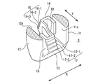
- FIG. 3 It is a front view of the band clip of 1st Embodiment of this invention. It is a perspective view which shows the clip of the band clip of FIG.
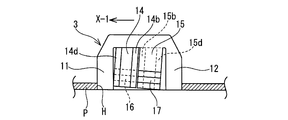
- FIG. 3 is a sectional view taken along line III-III in FIG. 1.
- (A) is the front view which shows the state which attached the said band clip to the wire harness
- (B) is a side view of (A)
- (C) shows the state which inserted and latched the band clip in the through-hole of the vehicle body panel.
- (A) is a perspective view explaining the tensile force of the longitudinal direction loaded on the said band clip
- (B) is drawing explaining the effect
- the band clip 1 is made of a resin molded product, and the wire harness mounting portion 2 and the clip 3 are integrally formed.
- the wire harness mounting portion 2 includes a rectangular tubular main body 5 provided with a band through hole 5a and a fastening band 6 protruding from the lower portion of the main body 5 on the outlet side of the band through hole 5a.
- the locking groove 6a is provided in a sawtooth shape.
- the fastening band 6 is wound around the electric wire group W constituting the wire harness W / H, inserted from the entrance of the band through hole 5a and penetrated, and protrudes from the inner peripheral surface of the band through hole 5a.
- the locking piece 5b is locked in the locking groove 6a and fixed to the wire harness W / H.
- the clip 3 includes a dish part 10 projecting from the outer surface of the main body 5, a pair of left and right support parts 11 and 12 projecting from the bottom of the dish part 10, and the support part A bridging portion 13 in which the projecting ends of 11 and 12 are connected, and a pair of blade portions 14 and 15 on the both sides of the bridging portion 13 in the lateral direction Y and in the longitudinal direction X to the left and right, and the base portion on the plate 10 side Projected in a folded shape toward the side.
- Locking claws 16 (16-1 to 16-3) and 17 (17-1 to 17-3) are arranged in three upper and lower stages on the outer surface inclined so that the base-side tips of the blades 14 and 15 protrude outward. ).
- Each of the locking claws 16 and 17 is formed as a triangular locking claw by inserting a V-shaped notch into the inclined outer surface of the blade portions 14 and 15.
- the lower surface of each locking claw 16 (17) is a hooking surface that locks the back surface of the opposing long side of the oblong mounting hole H of the vehicle body P.
- each blade portion 14 and 15 is provided with V-shaped cutouts at three upper and lower portions, and as described above, the upper and lower three-stage locking claws 16 (16-1 to 16-3), 17 (17-1 to 17-3) are provided.
- the pair of left and right support columns 11 and 12 have a semicircular cross section that fits inside the oval mounting hole H along the arc on the short side.
- the blade portions 14 and 15 are disposed between inner surfaces 11a and 12a formed of flat surfaces of the pair of left and right support columns 11 and 12 which face each other.
- the blade portions 14 and 15 are phased in the longitudinal direction, and a space is formed between the adjacent inner edges 14a and 15a, and the one blade portion 14 is adjacent to the one column portion 11, The other blade portion 15 is brought close to the other strut portion 12.
- Outer reinforcing portions 14d and 15d project from the outer edges 14c and 15c of the blade portions 14 and 15 toward the center in the short direction Y. These outer reinforcement portions 14d and 15d are provided along the entire length in the height direction of the blade portions 14 and 15, and are opposed to the column portions 11 and 12 with gaps therebetween. In addition, the base sides of the inner edges 14a and 15a of the blade portions 14 and 15 are connected by a central connecting portion 18 in the width direction.
- the band clip 1 configured as described above is wound around the wire group W constituting the wire harness W / H and wound around the band through hole 5a of the main body 5.
- the locking piece is locked in the locking groove 6a and fixed to the wire harness W / H.
- the wire harness W / H is routed along the routing route in the vehicle body, and the clip 3 of the band clip 1 is pushed into the oval mounting hole H provided in the vehicle body P from the bridging portion 13 side, and the blade portion 14 , 15 locking claws 16, 17 are locked to the inner peripheral edge of the mounting hole H and fixed.
- the lowermost locking claw 16 (16-1) is locked to the left side of one long side ha of the mounting hole H, and the lowermost locking claw 17 (17-). 1) is locked to the right side of the other long side hb of the mounting hole H facing each other. Further, the support columns 11 and 12 are fitted along the inner surfaces of the arc portions on the left and right short sides of the mounting hole H.
- the blade parts 14 and 15 are prevented from falling in the tension direction, and are provided on the blade parts 14 and 15. It is possible to prevent the claws 16 and 17 from being detached from the peripheral edge of the mounting hole H, and to increase the holding force of the clip 3.
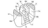
- the band clip of the second embodiment is directed from the adjacent inner edges 14a, 15a of the blades 14, 15 toward the center in the width direction, instead of eliminating the central connecting portion 18 provided in the band clip of the first embodiment.
- the inner reinforcing portions 14b and 15b are projected.
- the inner reinforcing portions 14b and 15b projecting from both sides in the width direction toward the center are overlapped at the center portion in the width direction. A minute gap is provided in this overlap portion.
- the inner reinforcing portion 14b of the blade portion 14 is parallel to the outer reinforcing portion 14d, and the blade portion 14 has a U-shaped cross section.
- the inner reinforcing portion 15b of the blade portion 15 is parallel to the outer reinforcing portion 15d, and the blade portion 15 has a U-shaped cross section. Since other configurations are the same as those of the band clip of the first embodiment, the same reference numerals are given and description thereof is omitted.
- the other blade portion is less likely to be interlocked with the fall of one blade portion, and the other blade portion 15 is on the X-1 side. If it falls down, the inner side reinforcement part 15b will contact the inner side reinforcement part 14b of the blade
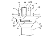
- notches 21 and 22 are provided on the outer surfaces of the base portions of the support portions 11 and 12 of the band clip of the first embodiment.
- the outer surfaces of the support columns 11 and 12 have a circular arc shape in cross section, and square cutouts 21 and 22 are provided in the center of the arc.
- the notches 21 and 22 are provided on the base side on the side of the dish 10 from the locking claws 16 and 17. Since other configurations are the same as those of the first embodiment, the same reference numerals are given and description thereof is omitted.
- a tensile force in the long side direction X-2 of the clip 3 acts as shown in FIG.
- the entire clip 3 including 11 and 12 is tilted, the notches 21 and 22 are caught on the periphery of the mounting hole H, and the clip 3 is difficult to be removed from the mounting hole H, and the holding force can be increased.
Landscapes
- Engineering & Computer Science (AREA)
- Mechanical Engineering (AREA)
- Architecture (AREA)
- Civil Engineering (AREA)
- Structural Engineering (AREA)
- Clamps And Clips (AREA)
- Installation Of Indoor Wiring (AREA)
- Package Frames And Binding Bands (AREA)
- Supports For Pipes And Cables (AREA)
- Insertion Pins And Rivets (AREA)
Abstract
ワイヤハーネスのバンドクリップにおいて保持力を高める。締結バンドを設けたワイヤハーネス取付部から突設する一対の支柱部の突出端を連結する架橋部に、幅方向の両側で且つ長さ方向に位相させて一対の羽根部を前記ワイヤハーネス取付部の基部側に向けて折り返し状に突設し、各羽根部の外面にそれぞれ係止爪を設け、該係止爪を車体の長円形状の取付穴の周縁に係止するクリップにおいて、前記各羽根部の長さ方向の両側端から幅方向の中央に向けて突出する内側補強部と外側補強部を設けて前記羽根部を断面コ字形状とし、前記一対の羽根部の隣接する内側補強部は突出部分をオーバラップさせ、前記外側補強部は前記支柱部の内面に隙間をあけて位置させ、前記羽根部が長軸方向へ倒れる時に、該倒れる方向側の羽根部の外側補強部は前記対向する支柱部に押し当てられると共に前記内側補強部同士が接触して反対側の羽根部の倒れ込みを抑制する構成としている。
Description
本発明はワイヤハーネス用のバンドクリップに関し、詳しくは、自動車等に配索するワイヤハーネスに取り付けられて車体の取付穴にクリップを挿入係止するバンドクリップにおいて、ワイヤハーネスに斜め方向の引っ張り力が作用してもクリップが取付穴から離脱しないようにするものである。
従来、この種のワイヤハーネス用のバンドクリップは種々提案されている。例えば、特開2001-72123号公報で提案されている図11(A)(B)に示すバンドクリップ100は、締結バンド102を本体103から突設したワイヤハーネス取付部101と、該ワイヤハーネス取付部101と一体成形したクリップ105とからなる。該クリップ105は本体103の外面に突設した皿部110から左右一対の支柱部111A、111Bを突設し、該一対の支柱部111Aと111Bの突出端を連結する架橋部112に、短手方向Yの両側で且つ長手方向Xで左右に位相させて一対の羽根部113A、113Bを皿部側に向けて折り返し状に突設し、各羽根部113A、113Bの外面にそれぞれ係止爪114A、114Bを設けている。
前記バンドクリップ100は締結バンド102をワイヤハーネスに巻き付けた後、本体103のバンド貫通穴103aに通し、締結バンド102に設けた係止溝にバンド貫通穴103aに突設した係止片を係止してワイヤハーネスに締結している。ワイヤハーネスを自動車の車体に沿って配索し、図11(B)に示すように車体に予め設けている長円状の取付穴Hにクリップ105を挿入し、羽根部113A、113Bを撓ませて取付穴Hに押し込み、係止爪114A、114Bを取付穴Hの長手方向Xの両側周縁に係止して、取付穴Hに固定している。
前記特許文献1のバンドクリップにおいて、図12に示すように、長手方向X(例えばX-1)の引張力が負荷されると、引張方向X-1に羽根部113A、113Bが倒れ込み、羽根部113A、113Bの係止爪114A、114Bが取付穴Hの周縁から外れ易くなる。其の際、羽根部113Aの外側端が支柱部111Aに押し当てられる可能性はあるが、支柱部111Aより外側にずれて倒れこみ、支柱部111Aに押し当てられない場合もある。このように、前記バンドクリップ100は長手方向Xの引張力に対して保持力が弱い問題がある。
本発明は前記した問題に鑑みてなされたもので、クリップが長軸方向の一方側に引っ張られた時に、引っ張られた側の羽根部の外側端を対向する支柱部に確実に押し当てて干渉させるようにし、羽根部に設けた係止爪が車体の取付穴から抜き出ないようにすることを課題としている。
前記課題を解決するため、第1の発明として、締結バンドを設けたワイヤハーネス取付部から突設する一対の支柱部の突出端を連結する架橋部に、幅方向の両側で且つ長さ方向に位相させて一対の羽根部を前記ワイヤハーネス取付部の基部側に向けて折り返し状に突設し、各羽根部の外面にそれぞれ係止爪を設け、該係止爪を車体の長円形状の取付穴の周縁に係止するクリップにおいて、
前記一対の羽根部の隣接側の基部同士を連結する中央連結部と、該中央連結部と反対側の前記一対の羽根部の外側縁から幅方向中央に向けて突出する外側補強部を設け、該各外側補強部を前記支柱部と隙間をあけて対向させ、前記羽根部が長軸方向へ倒れる時に前記外側補強部が対向する前記支柱部に接触する構成としていることを特徴とするワイヤハーネス用のバンドクリップを提供している。
前記一対の羽根部の隣接側の基部同士を連結する中央連結部と、該中央連結部と反対側の前記一対の羽根部の外側縁から幅方向中央に向けて突出する外側補強部を設け、該各外側補強部を前記支柱部と隙間をあけて対向させ、前記羽根部が長軸方向へ倒れる時に前記外側補強部が対向する前記支柱部に接触する構成としていることを特徴とするワイヤハーネス用のバンドクリップを提供している。
前記のように羽根部の外側縁から外側補強部を突設すると、長軸方向の引っ張り力が作用して、羽根部が引っ張られる長軸方向に倒れる時、該羽根部の外側補強部を外側に対向配置される支柱部に確実に押し当てることができる。これにより、羽根部の係止爪が車体の取付穴の周縁から外れることを防止でき、クリップの保持力を高めることができる。
また、第2の発明として、締結バンドを設けたワイヤハーネス取付部から突設する一対の支柱部の突出端を連結する架橋部に、幅方向の両側で且つ長さ方向に位相させて一対の羽根部を前記ワイヤハーネス取付部の基部側に向けて折り返し状に突設し、各羽根部の外面にそれぞれ係止爪を設け、該係止爪を車体の長円形状の取付穴の周縁に係止するクリップにおいて、
前記各羽根部の長さ方向の両側端から幅方向の中央に向けて突出する内側補強部と外側補強部を設けて前記羽根部を断面コ字形状とし、前記一対の羽根部の隣接する内側補強部は突出部分をオーバラップさせ、前記外側補強部は前記支柱部の内面に隙間をあけて位置させ、
前記羽根部が長軸方向へ倒れる時に、該倒れる方向側の羽根部の外側補強部は前記対向する支柱部に押し当てられると共に前記内側補強部同士が接触して反対側の羽根部の倒れ込みを抑制する構成としているワイヤハーネス用のクリップを提供している。
前記各羽根部の長さ方向の両側端から幅方向の中央に向けて突出する内側補強部と外側補強部を設けて前記羽根部を断面コ字形状とし、前記一対の羽根部の隣接する内側補強部は突出部分をオーバラップさせ、前記外側補強部は前記支柱部の内面に隙間をあけて位置させ、
前記羽根部が長軸方向へ倒れる時に、該倒れる方向側の羽根部の外側補強部は前記対向する支柱部に押し当てられると共に前記内側補強部同士が接触して反対側の羽根部の倒れ込みを抑制する構成としているワイヤハーネス用のクリップを提供している。
前記のように、第2の発明のバンドクリップでは、第1の発明で設けている中央連結部を設けずに、両側の羽根部にそれぞれ内側補強部をオーバラップさせて設け、羽根部が長軸方向に引っ張られて倒れ込み時に、前記内側補強部同士の接触により倒れ込む側と反対側の羽根部の倒れ込みを抑制し、該羽根部の係止爪が取付穴の周縁から外れないようにしている。
前記第1の発明および第2の発明のバンドクリップにおいて、前記クリップの支柱部の基部側の外側面に切欠を設け、該支柱部が傾斜した時に前記切欠が前記車体の取付穴の周縁に引っ掛かる構成としていることが好ましい。
前記切欠は羽根部の係止爪より皿部側(基部側)に設け、クリップの挿入係止時に支柱部の切欠が挿入力に影響を与えないようにしている。
前記切欠は羽根部の係止爪より皿部側(基部側)に設け、クリップの挿入係止時に支柱部の切欠が挿入力に影響を与えないようにしている。
前記支柱部は取付穴の両側円弧部に内嵌させているが、長軸方向の引張力が負荷されてクリップ自体が長軸方向に傾く時、支柱部も傾き、該支柱部の切欠が取付穴の周縁に引っ掛かり、クリップが取り付け穴から抜け出るのを防止することが出来る。
前記ワイヤハーネス取付部は前記締結バンドを突設した本体部の外面に皿部を突設し、該皿部の底面より前記一対の支柱部を突設している。
また、前記羽根部の外面に設ける係止爪は、羽根部の傾斜した外面の下部を切り欠いて三角形状の係止爪としている。該係止爪を複数段設け、取付穴を設けた車体の板厚に対応させることが好ましい。
また、前記羽根部の外面に設ける係止爪は、羽根部の傾斜した外面の下部を切り欠いて三角形状の係止爪としている。該係止爪を複数段設け、取付穴を設けた車体の板厚に対応させることが好ましい。
前記のように、本発明に係わるバンドクリップは長軸方向の一方側から引張力が負荷され、引っ張られた方向の一方の羽根部が支柱部に倒れ込んだ時、該羽根部に支柱部と対向する外側補強部を設けているため、該外側補強部を確実に支柱部に押し当ることができる。これにより、該羽根部の係止爪が取付穴の周縁から外れるのを防止でき、クリップの保持力を高めることができる。
以下、本発明の実施形態のバンドクリップを図面を参照して説明する。
図1乃至図5に本発明のバンドクリップの第1実施形態を示す。
バンドクリップ1は樹脂成形品からなり、ワイヤハーネス取付部2とクリップ3とを一体形成している。
図1乃至図5に本発明のバンドクリップの第1実施形態を示す。
バンドクリップ1は樹脂成形品からなり、ワイヤハーネス取付部2とクリップ3とを一体形成している。
ワイヤハーネス取付部2は、バンド貫通穴5aを設けた四角筒状の本体5と、バンド貫通穴5aの出口側の本体5の下部から突設した締結バンド6を備え、該締結バンド6の一面に係止溝6aを鋸歯状に設けている。該締結バンド6は図4に示すように、ワイヤハーネスW/Hを構成する電線群Wに巻き付けてバンド貫通穴5aの入口から挿入して貫通させ、バンド貫通穴5aの内周面より突設した係止片5bを前記係止溝6aに係止してワイヤハーネスW/Hに固定するようにしている。
図2および図3に示すように、クリップ3は前記本体5の外面に突設した皿部10と、該皿部10の底部から突設した左右一対の支柱部11、12と、該支柱部11と12の突出端を連結した架橋部13と、該架橋部13の短手方向Yの両側で且つ長手方向Xで左右に位相させて一対の羽根部14、15を皿部10側の基部側に向けて折り返し状に突設している。各羽根部14、15の基部側先端が外方に突出するように傾斜させた外面に上下3段に係止爪16(16-1~16-3)、17(17-1~17-3)をそれぞれ設けている。
前記各係止爪16、17は羽根部14、15の傾斜した外面にV状の切欠を入れて三角形状の係止爪としている。図4(C)に示すように、各係止爪16(17)の下面を車体Pの長円形状の取付穴Hの対向する長辺側の周縁の裏面に係止する引掛面としている。図2に示すように、各羽根部14、15には上下3カ所にV状の切欠を設け、前記のように、上下3段の係止爪16(16-1~16-3)、17(17-1~17-3)を設けている。
前記左右一対の支柱部11、12は長円形状の取付穴H内において、短辺側の円弧部に沿って夫れ夫れ内嵌する断面半円形状としている。該左右一対の支柱部11、12の対向する平坦面からなる内面11a、12aの間に、前記羽根部14、15を配置している。
羽根部14、15は、前記のように、長手方向で位相させていると共に、近接する内側縁14a、15aの間に空間をあけ、一方の羽根部14は一方の支柱部11に近接させ、他方の羽根部15は他方の支柱部12に近接させている。
前記各羽根部14、15の外側縁14c、15cから短手方向Yの中央に向けて外側補強部14d、15dを突設している。これら外側補強部14d、15dは羽根部14、15の高さ方向全長に沿って設け、支柱部11、12とそれぞれ隙間をあけて対向させている。また、羽根部14、15の内側縁14aと15aの基部側を幅方向の中央連結部18で連結している。
前記構成としたバンドクリップ1は図4(A)(B)(C)に示すように、締結バンド6をワイヤハーネスW/Hを構成する電線群Wに巻き付け、本体5のバンド貫通穴5aに通し、バンド貫通穴5a内で係止溝6aに係止片を係止してワイヤハーネスW/Hに固定している。
該ワイヤハーネスW/Hを車体に配索経路に沿って配索し、車体Pに設けた長円形状の取付穴Hに前記バンドクリップ1のクリップ3を架橋部13側から押し込み、羽根部14、15の係止爪16、17を取付穴Hの内周縁に係止して固定している。
該ワイヤハーネスW/Hを車体に配索経路に沿って配索し、車体Pに設けた長円形状の取付穴Hに前記バンドクリップ1のクリップ3を架橋部13側から押し込み、羽根部14、15の係止爪16、17を取付穴Hの内周縁に係止して固定している。
詳細には、本実施形態では、最下段の係止爪16(16-1)が取付穴Hの対向する一方の長辺haの左側に係止し、最下段の係止爪17(17-1)が取付穴Hの対向する他方の長辺hbの右側に係止している。また、取付穴Hの左右の短辺側の円弧部の内面に沿って支柱部11、12が内嵌している。
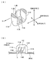
前記のようにクリップ3が取付穴Hに係止している状態で、バンドクリップ1の締結バンド6で締結されたワイヤハーネスW/Hから、図5に示すように、取付穴Hの長手方向Xの一方側X-1への引張力が負荷されると、引張方向X-1側の一方の羽根部14が支柱部11に押し当たるように倒れこみ、該羽根部14の係止爪16が取付穴Hの周縁から外れるのを防止できる。
長軸方向の他方側X-2から引張力が負荷されると、引張方向X-2側の他方の羽根部15が支柱部12に押し当たるように倒れこみ、該羽根部15の係止爪17が取付穴Hの周縁から外れるのを防止できる。
長軸方向の他方側X-2から引張力が負荷されると、引張方向X-2側の他方の羽根部15が支柱部12に押し当たるように倒れこみ、該羽根部15の係止爪17が取付穴Hの周縁から外れるのを防止できる。
また、短辺方向Yに引張力が作用すると、羽根部14と15を中央連結部18で連結しているため、短辺方向Yのいずれの方向にも大きく倒れこむ事は出来ず、羽根部14、15の係止爪16、17が取付穴Hの周縁から外れるのを防止できる。
このように、長軸方向および短軸方向のいずれの方向から引張力が負荷されても、羽根部14、15の引張方向への倒れ込みを抑制して、羽根部14、15に設けた係止爪16、17が取付穴Hの周縁から外れるのを防止でき、クリップ3の保持力を高めることができる。
図6乃至図8に第2実施形態のバンドクリップを示す。
第2実施形態のバンドクリップは、第1実施形態のバンドクリップで設けている中央連結部18を無くす代わりに、各羽根部14、15の隣接する内側縁14a、15aから幅方向の中央に向けて内側補強部14b、15bを突設している。幅方向の両側から中央に向けて突設する内側補強部14bと15bは幅方向の中央部でオーバラップさせている。このオーバラップ部分では微小の隙間を設けている。
羽根部14の内側補強部14bは外側補強部14dと平行とし、羽根部14を断面コ字形状としている。同様に、羽根部15の内側補強部15bは外側補強部15dと平行とし、羽根部15を断面コ字形状としている。
他の構成は第1実施形態のバンドクリップと同様であるため、同一符号を付して説明を省略する。
第2実施形態のバンドクリップは、第1実施形態のバンドクリップで設けている中央連結部18を無くす代わりに、各羽根部14、15の隣接する内側縁14a、15aから幅方向の中央に向けて内側補強部14b、15bを突設している。幅方向の両側から中央に向けて突設する内側補強部14bと15bは幅方向の中央部でオーバラップさせている。このオーバラップ部分では微小の隙間を設けている。
羽根部14の内側補強部14bは外側補強部14dと平行とし、羽根部14を断面コ字形状としている。同様に、羽根部15の内側補強部15bは外側補強部15dと平行とし、羽根部15を断面コ字形状としている。
他の構成は第1実施形態のバンドクリップと同様であるため、同一符号を付して説明を省略する。
前記バンドクリップでは、図8に示すように、長軸方向X-1の引張力がクリップ3に負荷された時、引っ張られた側の羽根部14の外側補強部14dが対向する支柱部11に倒れ込んで押し当てられる。これにより羽根部14の係止爪16が取付穴Hの周縁から外れるのを防止できる。倒れ方向の反対側の羽根部15がX-1の方向に倒れ込んでも保持力の向上に寄与せず、逆に羽根部15の係止爪17が取付穴Hの周縁を移動して外れ易くなる。よって、反対側の羽根部15の倒れ込みは抑制することが好ましい。
本実施形態では、羽根部14と15を中央連結部で連結していないため、一方の羽根部の倒れ込みに他方の羽根部が連動しにくくし、かつ、他方の羽根部15がX-1側へ倒れ込むと内側補強部15bが羽根部14の内側補強部14bと接触して羽根部15の倒れ込みを抑制できる。これにより、両側の羽根部14、15の係止爪16、17が取付穴Hの周縁から外れにくくして、クリップ3の保持力を高めることができる。
図9および図10に第3実施形態のバンドクリップを示す。
第3実施形態のバンドクリップは、第1実施形態のバンドクリップの支柱部11、12の基部側の外面に切欠21、22を設けている。支柱部11、12の外面は断面円弧形状であり、該円弧の中央部に四角状の切欠21、22を設けている。該切欠21、22は係止爪16、17より皿部10側の基部側に設けている。
他の構成は第1実施形態と同様であるため同一符号を付して説明を省略する。
第3実施形態のバンドクリップは、第1実施形態のバンドクリップの支柱部11、12の基部側の外面に切欠21、22を設けている。支柱部11、12の外面は断面円弧形状であり、該円弧の中央部に四角状の切欠21、22を設けている。該切欠21、22は係止爪16、17より皿部10側の基部側に設けている。
他の構成は第1実施形態と同様であるため同一符号を付して説明を省略する。
前記のように支柱部11、12の基部側の外面に切欠21、22を設けておくと、図10に示すように、クリップ3の長辺方向X-2の引張力が作用し、支柱部11、12を含めてクリップ3の全体が傾くと、切欠21、22が取付穴Hの周縁に引っ掛かり、クリップ3が取付穴Hから抜けでにくくなり、保持力を高めることができる。
1 バンドクリップ
2 ワイヤハーネス取付部
3 クリップ
5 本体
6 締結バンド
10 皿部
11、12 支柱部
14、15 羽根部
14b、15b 内側補強部
14d、15d 外側補強部
16、17 係止爪
18 中央連結部
W/H ワイヤハーネス
P 車体
H 取付穴
2 ワイヤハーネス取付部
3 クリップ
5 本体
6 締結バンド
10 皿部
11、12 支柱部
14、15 羽根部
14b、15b 内側補強部
14d、15d 外側補強部
16、17 係止爪
18 中央連結部
W/H ワイヤハーネス
P 車体
H 取付穴
Claims (3)
- 締結バンドを設けたワイヤハーネス取付部から突設する一対の支柱部の突出端を連結する架橋部に、幅方向の両側で且つ長さ方向に位相させて一対の羽根部を前記ワイヤハーネス取付部の基部側に向けて折り返し状に突設し、各羽根部の外面にそれぞれ係止爪を設け、該係止爪を車体の長円形状の取付穴の周縁に係止するクリップにおいて、
前記一対の羽根部の隣接側の基部同士を連結する中央連結部と、該中央連結部と反対側の前記一対の羽根部の外側縁から幅方向中央に向けて突出する外側補強部を設け、該各外側補強部を前記支柱部と隙間をあけて対向させ、前記羽根部が長軸方向へ倒れる時に前記外側補強部が対向する前記支柱部に接触する構成としていることを特徴とするワイヤハーネス用のバンドクリップ。 - 締結バンドを設けたワイヤハーネス取付部から突設する一対の支柱部の突出端を連結する架橋部に、幅方向の両側で且つ長さ方向に位相させて一対の羽根部を前記ワイヤハーネス取付部の基部側に向けて折り返し状に突設し、各羽根部の外面にそれぞれ係止爪を設け、該係止爪を車体の長円形状の取付穴の周縁に係止するクリップにおいて、
前記各羽根部の長さ方向の両側端から幅方向の中央に向けて突出する内側補強部と外側補強部を設けて前記羽根部を断面コ字形状とし、前記一対の羽根部の隣接する内側補強部は突出部分をオーバラップさせ、前記外側補強部は前記支柱部の内面に隙間をあけて位置させ、
前記羽根部が長軸方向へ倒れる時に、該倒れる方向側の羽根部の外側補強部は前記対向する支柱部に押し当てられると共に前記内側補強部同士が接触して反対側の羽根部の倒れ込みを抑制する構成としているワイヤハーネス用のバンドクリップ。 - 前記クリップの支柱部の基部側の外側面に切欠を設け、該支柱部が傾斜した時に前記切欠が前記車体の取付穴の周縁に引っ掛かる構成としている請求項1または請求項2に記載のワイヤハーネス用のバンドクリップ。
Applications Claiming Priority (2)
| Application Number | Priority Date | Filing Date | Title |
|---|---|---|---|
| JP2011-068173 | 2011-03-25 | ||
| JP2011068173A JP2012205403A (ja) | 2011-03-25 | 2011-03-25 | ワイヤハーネス用のバンドクリップ |
Publications (1)
| Publication Number | Publication Date |
|---|---|
| WO2012132544A1 true WO2012132544A1 (ja) | 2012-10-04 |
Family
ID=46930311
Family Applications (1)
| Application Number | Title | Priority Date | Filing Date |
|---|---|---|---|
| PCT/JP2012/052415 Ceased WO2012132544A1 (ja) | 2011-03-25 | 2012-02-02 | ワイヤハーネス用のバンドクリップ |
Country Status (2)
| Country | Link |
|---|---|
| JP (1) | JP2012205403A (ja) |
| WO (1) | WO2012132544A1 (ja) |
Cited By (2)
| Publication number | Priority date | Publication date | Assignee | Title |
|---|---|---|---|---|
| WO2016032507A1 (en) * | 2014-08-29 | 2016-03-03 | Avery Dennison Corporation | Fastner with reusable insert fastening element |
| US20210394696A1 (en) * | 2020-06-23 | 2021-12-23 | Toyota Jidosha Kabushiki Kaisha | Clip and vehicle curtain airbag device |
Citations (4)
| Publication number | Priority date | Publication date | Assignee | Title |
|---|---|---|---|---|
| JP2002305832A (ja) * | 2001-04-03 | 2002-10-18 | Nissan Motor Co Ltd | 偏平部材取付具 |
| JP2007532419A (ja) * | 2004-04-09 | 2007-11-15 | エイベリィ デニスン コーポレイション | インサートファスナ付きケーブルタイ |
| JP2008049802A (ja) * | 2006-08-24 | 2008-03-06 | Piolax Inc | クリップ |
| JP2010151174A (ja) * | 2008-12-24 | 2010-07-08 | Nippon Pop Rivets & Fasteners Ltd | クリップ |
-
2011
- 2011-03-25 JP JP2011068173A patent/JP2012205403A/ja not_active Withdrawn
-
2012
- 2012-02-02 WO PCT/JP2012/052415 patent/WO2012132544A1/ja not_active Ceased
Patent Citations (4)
| Publication number | Priority date | Publication date | Assignee | Title |
|---|---|---|---|---|
| JP2002305832A (ja) * | 2001-04-03 | 2002-10-18 | Nissan Motor Co Ltd | 偏平部材取付具 |
| JP2007532419A (ja) * | 2004-04-09 | 2007-11-15 | エイベリィ デニスン コーポレイション | インサートファスナ付きケーブルタイ |
| JP2008049802A (ja) * | 2006-08-24 | 2008-03-06 | Piolax Inc | クリップ |
| JP2010151174A (ja) * | 2008-12-24 | 2010-07-08 | Nippon Pop Rivets & Fasteners Ltd | クリップ |
Cited By (3)
| Publication number | Priority date | Publication date | Assignee | Title |
|---|---|---|---|---|
| WO2016032507A1 (en) * | 2014-08-29 | 2016-03-03 | Avery Dennison Corporation | Fastner with reusable insert fastening element |
| US20210394696A1 (en) * | 2020-06-23 | 2021-12-23 | Toyota Jidosha Kabushiki Kaisha | Clip and vehicle curtain airbag device |
| US12151634B2 (en) * | 2020-06-23 | 2024-11-26 | Toyota Jidosha Kabushiki Kaisha | Clip and vehicle curtain airbag device |
Also Published As
| Publication number | Publication date |
|---|---|
| JP2012205403A (ja) | 2012-10-22 |
Similar Documents
| Publication | Publication Date | Title |
|---|---|---|
| US20100186197A1 (en) | Harness clip structure | |
| WO2012056747A1 (ja) | バンドクリップ | |
| WO2008014250B1 (en) | Structural reinforcements | |
| WO2010073872A1 (ja) | クリップ | |
| JP2010166750A (ja) | ワイヤハーネス用プロテクタ | |
| JP2018071562A (ja) | 留め具 | |
| WO2012132544A1 (ja) | ワイヤハーネス用のバンドクリップ | |
| JP2008049721A (ja) | 吸音材取付構造 | |
| JP5181889B2 (ja) | 樹脂容器構造 | |
| JP2012157105A (ja) | ワイヤハーネス用のバンド | |
| JP5617720B2 (ja) | ワイヤハーネス用のバンドクリップ | |
| WO2012120721A1 (ja) | ワイヤハーネス用のバンドクリップ | |
| US9197043B2 (en) | Tape winding structure at wire guiding out portion | |
| JP2016205113A (ja) | ワイヤー止め金具 | |
| JP2017158352A (ja) | 電線束支持クリップおよびこれを備えたワイヤハーネス | |
| JP2017141940A (ja) | アンカークリップ構造およびバンドクリップ | |
| JP2007155007A (ja) | 部材固定用クリップ構造 | |
| JP5807585B2 (ja) | ワイヤハーネス用のバンドクリップ | |
| JP5516161B2 (ja) | スタッドボルト用固定機構 | |
| WO2019176221A1 (ja) | ワイヤハーネス用プロテクタおよびそれを用いたワイヤハーネスの配索構造 | |
| JP2015033314A (ja) | 結束バンドの取付構造 | |
| JP6322105B2 (ja) | アース端子ユニット | |
| JP2013090521A (ja) | ワイヤハーネス用バンド | |
| JP5923260B2 (ja) | プロテクタ及びプロテクタのロック方法 | |
| JP2012182940A (ja) | バンドクリップ |
Legal Events
| Date | Code | Title | Description |
|---|---|---|---|
| 121 | Ep: the epo has been informed by wipo that ep was designated in this application |
Ref document number: 12763172 Country of ref document: EP Kind code of ref document: A1 |
|
| NENP | Non-entry into the national phase |
Ref country code: DE |
|
| 122 | Ep: pct application non-entry in european phase |
Ref document number: 12763172 Country of ref document: EP Kind code of ref document: A1 |