WO2012132517A1 - Système de nébuliseur et dispositif de chauffage utilisé dans ledit système de nébuliseur - Google Patents
Système de nébuliseur et dispositif de chauffage utilisé dans ledit système de nébuliseur Download PDFInfo
- Publication number
- WO2012132517A1 WO2012132517A1 PCT/JP2012/051396 JP2012051396W WO2012132517A1 WO 2012132517 A1 WO2012132517 A1 WO 2012132517A1 JP 2012051396 W JP2012051396 W JP 2012051396W WO 2012132517 A1 WO2012132517 A1 WO 2012132517A1
- Authority
- WO
- WIPO (PCT)
- Prior art keywords
- bottle
- nebulizer
- liquid
- heater device
- adapter
- Prior art date
Links
Images


Classifications
-
- A—HUMAN NECESSITIES
- A61—MEDICAL OR VETERINARY SCIENCE; HYGIENE
- A61M—DEVICES FOR INTRODUCING MEDIA INTO, OR ONTO, THE BODY; DEVICES FOR TRANSDUCING BODY MEDIA OR FOR TAKING MEDIA FROM THE BODY; DEVICES FOR PRODUCING OR ENDING SLEEP OR STUPOR
- A61M11/00—Sprayers or atomisers specially adapted for therapeutic purposes
- A61M11/02—Sprayers or atomisers specially adapted for therapeutic purposes operated by air or other gas pressure applied to the liquid or other product to be sprayed or atomised
-
- A—HUMAN NECESSITIES
- A61—MEDICAL OR VETERINARY SCIENCE; HYGIENE
- A61M—DEVICES FOR INTRODUCING MEDIA INTO, OR ONTO, THE BODY; DEVICES FOR TRANSDUCING BODY MEDIA OR FOR TAKING MEDIA FROM THE BODY; DEVICES FOR PRODUCING OR ENDING SLEEP OR STUPOR
- A61M16/00—Devices for influencing the respiratory system of patients by gas treatment, e.g. mouth-to-mouth respiration; Tracheal tubes
- A61M16/10—Preparation of respiratory gases or vapours
- A61M16/1075—Preparation of respiratory gases or vapours by influencing the temperature
- A61M16/109—Preparation of respiratory gases or vapours by influencing the temperature the humidifying liquid or the beneficial agent
-
- A—HUMAN NECESSITIES
- A61—MEDICAL OR VETERINARY SCIENCE; HYGIENE
- A61M—DEVICES FOR INTRODUCING MEDIA INTO, OR ONTO, THE BODY; DEVICES FOR TRANSDUCING BODY MEDIA OR FOR TAKING MEDIA FROM THE BODY; DEVICES FOR PRODUCING OR ENDING SLEEP OR STUPOR
- A61M16/00—Devices for influencing the respiratory system of patients by gas treatment, e.g. mouth-to-mouth respiration; Tracheal tubes
- A61M16/10—Preparation of respiratory gases or vapours
- A61M16/14—Preparation of respiratory gases or vapours by mixing different fluids, one of them being in a liquid phase
- A61M16/16—Devices to humidify the respiration air
-
- A—HUMAN NECESSITIES
- A61—MEDICAL OR VETERINARY SCIENCE; HYGIENE
- A61M—DEVICES FOR INTRODUCING MEDIA INTO, OR ONTO, THE BODY; DEVICES FOR TRANSDUCING BODY MEDIA OR FOR TAKING MEDIA FROM THE BODY; DEVICES FOR PRODUCING OR ENDING SLEEP OR STUPOR
- A61M11/00—Sprayers or atomisers specially adapted for therapeutic purposes
- A61M11/06—Sprayers or atomisers specially adapted for therapeutic purposes of the injector type
-
- A—HUMAN NECESSITIES
- A61—MEDICAL OR VETERINARY SCIENCE; HYGIENE
- A61M—DEVICES FOR INTRODUCING MEDIA INTO, OR ONTO, THE BODY; DEVICES FOR TRANSDUCING BODY MEDIA OR FOR TAKING MEDIA FROM THE BODY; DEVICES FOR PRODUCING OR ENDING SLEEP OR STUPOR
- A61M2205/00—General characteristics of the apparatus
- A61M2205/33—Controlling, regulating or measuring
- A61M2205/3368—Temperature
-
- A—HUMAN NECESSITIES
- A61—MEDICAL OR VETERINARY SCIENCE; HYGIENE
- A61M—DEVICES FOR INTRODUCING MEDIA INTO, OR ONTO, THE BODY; DEVICES FOR TRANSDUCING BODY MEDIA OR FOR TAKING MEDIA FROM THE BODY; DEVICES FOR PRODUCING OR ENDING SLEEP OR STUPOR
- A61M2205/00—General characteristics of the apparatus
- A61M2205/36—General characteristics of the apparatus related to heating or cooling
- A61M2205/3653—General characteristics of the apparatus related to heating or cooling by Joule effect, i.e. electric resistance
Definitions
- the present invention relates to a nebulizer system that adds moisture (water vapor or mist-like water) to a gas such as air or oxygen, and a heater device used in the nebulizer system.
- oxygen therapy for supplying oxygen has been performed on patients of the respiratory system.
- oxygen generated from an oxygen cylinder or oxygen concentrated by an oxygen concentrator composed of an adsorbent such as molecular sieve is used for nasal passage. It is supplied to patients using cannula and mask. Since oxygen supplied from an oxygen cylinder or the like contains almost no moisture, it is necessary to prevent the airway from drying when oxygen is supplied into the airway such as the patient's nasal cavity. Therefore, a humidifier is provided in the middle of the oxygen supply tube to supply humidified oxygen.
- a nebulizer system is known as a humidifier used for humidifying oxygen (see, for example, Patent Document 1).
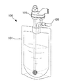
- the nebulizer system is connected to a bottle (container) 101 containing a solution in which a drug is dissolved and a liquid such as sterilized water, purified water, distilled water, and physiological saline, and the bottle 101.
- the nebulizer adapter 110 is provided.
- the nebulizer system 100 supplies gas such as oxygen gas into the adapter 110, thereby sucking air while sucking up the sterilized water contained in the bottle 101, and using the sucked sterilized water as a fine aerosol with high oxygen content.
- the nebulizer system 100 includes a drain tube 105 that connects the nebulizer adapter 110 and the bottle 101 in order to return the liquid that has not been aerosolized in the adapter 110 to the bottle (container) 101.
- a heater device is interposed between the bottle (container) and the adapter to heat the sterilized water while sucking up the sterilized water contained in the bottle, There is a case in which a gas having a high oxygen concentration as an aerosol is humidified and supplied to a patient.
- the nebulizer system described above includes a drain tube that connects the nebulizer adapter and the bottle as a structure for returning the liquid droplets accumulated in the nebulizer adapter to the bottle.
- a drain tube that connects the nebulizer adapter and the bottle as a structure for returning the liquid droplets accumulated in the nebulizer adapter to the bottle.
- the drain tube may come into contact with various objects (human body, desk, bed, wall, etc.) in the hospital room.
- the drain tube tip that needs to be kept will be contaminated.
- the present invention provides a nebulizer system in which a bottle, a heater device, and a nebulizer adapter can be easily connected, and which excludes a drain tube that is exposed to the outside and is obstructed, and a heater device that is preferably used in the nebulizer system. With the goal.
- the above-mentioned object of the present invention is a nebulizer system comprising a bottle having a bottle mouth portion at an upper portion thereof and storing a liquid, a heater device connectable to the bottle mouth portion, and a nebulizer adapter connectable to the heater device.
- the bottle includes a dip tube immersed in a liquid stored therein, and an upper end portion of the dip tube is provided with a gap portion that communicates the inside and outside of the bottle via the bottle mouth portion.
- the nebulizer adapter is disposed on the inner side of the peripheral wall of the bottle mouth portion, the nozzle member having an ejection port for injecting gas, and the nozzle member disposed at a position corresponding to the ejection port and ejected from the ejection port.
- An aerosol forming member that draws the liquid in the bottle through the dip tube and the heater device by a gas flow and uses the sucked liquid as a fine aerosol;
- the heater device has one end connected to the upper end of the dip tube and the other end connected to the aerosol forming member, a heating unit for heating the water guide tube, and one end connected to the gap.
- a nebulizer system that includes a drain pipe that is disposed opposite to the part and returns the liquid that has not been aerosolized in the nebulizer adapter through the other end into the bottle.
- the liquid that has not been aerosolized can be returned to the bottle through the drain pipe disposed inside the heater device.
- the nebulizer adapter and the bottle are connected, and the drain tube placed outside the bottle is no longer necessary, and the human hand or object is caught on the drain tube, causing the nebulizer system to collapse. Can be effectively prevented.
- the nebulizer adapter does not need to be provided with a drain tube, the handling of the operation of connecting the socket portion of the nebulizer adapter to the connection portion of the heater device can be made extremely good.
- the heater device includes a liquid receiving part that stores liquid that has not been aerosolized in the nebulizer adapter, and the other end of the drain pipe is connected to the liquid receiving part.
- the said liquid receiving part is provided in the other end part side of the said water conduit, and is provided with the bottom part and the side wall part standingly arranged from the said bottom part.
- the liquid that has not been aerosolized in the nebulizer adapter can be collected in the liquid receiving part, and the liquid can be efficiently refluxed to the bottle via the drain pipe inside the heater device.
- the other end portion of the water conduit is inserted into the bottom portion of the liquid receiving portion, and the side wall portion is erected from the outer peripheral edge of the bottom portion.
- the liquid collection area of the liquid receiving part can be set wide, and the liquid that has not been aerosolized in the nebulizer adapter can be collected efficiently. It is also possible to connect a plurality of drain pipes to the bottom of the liquid receiving part, and it is possible to efficiently and quickly return the liquid accumulated in the liquid receiving part without being aerosolized.
- the heater device includes a housing and a cylindrical connection portion that protrudes from the housing and is connected to the nebulizer adapter, and the nebulizer adapter has a contact surface that can be in close contact with an end surface of the connection portion. It is preferable to have the ring-shaped member which has.
- the water conduit and the drain pipe are formed in a straight line. According to such a structure, it becomes possible to wash
- one side surface of the heater device and one side surface of the bottle are substantially flush with each other.
- the nebulizer system can be installed by bringing one side surface of the heater device and one side surface of the bottle, which are substantially flush with each other, into contact with a planar member such as a wall, thereby saving the installation area.
- the installation posture of the nebulizer system can be stabilized.
- the object of the present invention is to arrange between a bottle having a bottle mouth portion at the top and storing a liquid and a nebulizer adapter that sucks the liquid in the bottle and uses the sucked liquid as a fine aerosol.
- a heater device for a nebulizer system installed, one end connected to an end of a dip tube included in the bottle, and the other end connected to a pipe-shaped aerosol forming member included in the nebulizer adapter;
- a heating unit that heats the water conduit, and a liquid that has not been aerosolized in the nebulizer adapter is disposed so that one end faces the inside of the bottle mouth and the other end faces the inside of the nebulizer adapter. This is achieved by a heater device having a drain pipe that circulates in the bottle.
- the liquid that has not been aerosolized can be returned to the bottle via the drain pipe disposed inside the heater device. Therefore, there is no need for a conventional drain tube that connects between the nebulizer adapter and the bottle and is placed outside the bottle, and a nebulizer system in which a human hand or object is caught on the drain tube and the heater device is disposed. It can prevent effectively that it falls down.
- a nebulizer system in which a bottle, a heater device, and a nebulizer adapter can be easily connected, and a drain tube that is exposed to the outside is obstructed, and a heater device that is preferably used in the nebulizer system. Can do.
- FIG. 5 is a cross-sectional view taken along line AA in FIG. 4.
- FIG. 5 is a sectional view taken along line BB in FIG. 4.
- A) is a schematic structure perspective view of the dip tube shown in FIG. 6,
- (b) is a schematic structure sectional drawing of a dip tube,
- (c) was seen from the arrow C direction in FIG.8 (b).
- FIG. 8D is an enlarged plan view
- FIG. 8D is a cross-sectional view taken along the line DD in FIG.
- (A) is a principal part expanded sectional view of a diffuser part
- (b) is a principal part enlarged front view of a diffuser part.
- It is a schematic structure principal part expanded sectional view of the nebulizer system shown in FIG.
- It is a principal part schematic block diagram which shows the EE cross section of FIG.
- It is a principal part enlarged view which shows the connection state with the connection part with which a heater apparatus is provided, and a bottle mouth part.
- It is a principal part enlarged view which shows the connection state of the socket part with which a nebulizer adapter is provided, and the connection part with which a heater apparatus is provided.
- (A) is a plan view showing a modified example of the liquid receiving portion provided in the heater device, (b) is a sectional view taken along line FF, and (c) is a water guide pipe and a drain in the liquid receiving portion. It is a block diagram which shows the state which connected the flow path pipe to the conduit pipe while connecting a pipe
- (A) is a plan view showing another modification of the liquid receiving part shown in FIG. 14, (b) is a GG cross-sectional view thereof, and (c) is a water guide pipe in the liquid receiving part.
- FIG. 1 is a perspective view of a nebulizer system according to an embodiment of the present invention.
- a nebulizer system 1 is an apparatus for supplying humidified breathing gas, for example. As shown in FIG. 1, as shown in FIG. The apparatus 3 and the nebulizer adapter 4 arrange
- the bottle 2 is a container that stores therein a solution in which a drug is dissolved or a liquid such as sterilized water, purified water, distilled water, and physiological saline.
- a dip tube 22 is a front view of the bottle 2
- FIG. 3 is a left side view thereof.
- 4 is a plan view of the bottle 2
- FIG. 5 is a bottom view thereof.
- 6 is a cross-sectional view taken along line AA in FIG. 4
- FIG. 7 is a cross-sectional view taken along line BB in FIG.
- the bottle body 21 includes a body portion 211 having a substantially rectangular horizontal cross section, a bottom portion 212 that seals the lower end of the body portion 211, and a bottle mouth portion 25 that is provided on the upper end of the body portion 211 via a shoulder portion. It has. On each side surface of the body portion 211, a volume-reducing rib 213 configured by a single linear recess or a combination of a plurality of linear recesses is formed. These volume-reducing ribs 213 are ribs for bending the side surface of the body portion 211 when the body portion 211 is crushed.
- the bottle body By pressing the front surface and the back surface of the body portion 211 and crushing the bottle body 21, the bottle body The volume can be reduced by folding in a mountain fold along the volume reducing rib 213 formed on the side surface of the bottle 21 and then folding along the volume reducing rib 213 formed on the front and back surfaces of the bottle 2.
- Leg portions 214 are provided at the four corners of the bottom portion 212 of the bottle main body 21 in order to enhance the stability when the bottle 2 is placed.
- the leg 214 is formed so as to protrude outward from the bottom 212 downward in the vertical direction.
- a storage part 215 having a circular shape in plan view is formed in which the inner bottom surface of the bottle body 21 is recessed downward in the vertical direction.
- the storage portion 215 is formed so that the center in plan view overlaps the axis of the bottle mouth portion 25.
- a pressure-resistant rib 216 is formed around the storage portion 215 so as to surround the storage portion 215.
- the pressure-resistant rib 216 is formed so as to protrude outward from the bottom 212 of the bottle body 21 in the vertical direction. It should be noted that the pressure rib 216 is formed so that the bottom portion 212 of the bottle 2 is not affected by the increase in internal pressure or the influence of heat when wet heat sterilization (for example, autoclave sterilization) is performed after filling the bottle 2 with the content liquid and closing. It is provided to prevent deformation such as swelling.
- the bottle mouth portion 25 is provided at an upper portion of the bottle body 21 and includes a screw portion 251 to which a screw-structured lid 10 (see FIG. 7) can be attached.
- the screw portion 251 is formed on the outer peripheral surface of the peripheral wall 25 a of the bottle mouth portion 25.
- the peripheral wall 25a below the screw portion 251 is formed to have a thick structure, and the thick structure portion A plurality of protrusions 252 as stoppers are provided on the outer peripheral portion.
- the bottle 2 according to this embodiment has a structure that can be sealed and sterilized.
- the bottle mouth portion 25 includes an engaging portion 253 below the thick-walled structure portion where the protrusion 252 as a stopper is formed.
- the engaging portion 253 is configured as a set of a plurality of protruding bodies 253a that protrude outward from the peripheral wall 25a of the bottle mouth portion 25 in the horizontal direction.
- the engaging portion 253 is fitted with the connecting portion 37 of the heater device 3.
- an olefin polymer is used as the material for forming the bottle body 21.
- Typical examples of the olefin polymer include polyethylene and polypropylene-based polymers.
- polyethylene include high density polyethylene (HDPE), low density polyethylene (LDPE), and blends thereof (HDPE / LDPE).
- polypropylene-based polymer include polypropyne, random (or block) copolymers of polypropyne and other ⁇ -olefins such as ethylene, syndiotactic polypropylene, and blends thereof.
- the dip tube 22 is a tubular body that is immersed in the liquid stored in the bottle body 21, and includes a tube body 221, a fixing portion 222, and a diffuser portion 23, as shown in FIGS. .
- 8A is a schematic configuration perspective view of the dip tube 22, and FIG. 8B is a schematic cross-sectional view of the dip tube 22.
- FIG. 8C is an enlarged plan view as viewed from the direction of arrow C in FIG. 8B
- FIG. 8D is a cross-sectional view taken along the line DD in FIG. 8C.
- the pipe body 221 is configured by a straight pipe, and a fixed portion 222 is connected to one end (upper end) thereof, and a diffuser portion 23 is connected to the other end (lower end).
- the length of the tube body 221 is set so that the other end is in the vicinity of the bottom 212 of the bottle body 21 when one end is disposed inside the bottle mouth portion 25 (in the region surrounded by the peripheral wall 25a). ing.
- the fixing portion 222 is a member for installing the dip tube 22 in the bottle 2, and holds the tubular annular body 223 disposed inside the bottle mouth portion 25 and the tube body 221 inside the annular body 223. And a holding member 224 for fixing.
- the annular body 223 is disposed at a position where the axial center thereof substantially overlaps with the axial center of the bottle mouth portion 25.
- a flange portion 225 is provided at the upper end portion of the annular body 223, and the dip tube 22 can be installed in the bottle body 21 by fitting the flange portion 225 to the upper end portion of the bottle mouth portion 25. It becomes possible.
- the inner periphery of the annular body 223 and the bottle mouth portion 25 is formed.
- the annular body 223 is disposed inside the bottle mouth portion 25 so as to be spaced apart from the peripheral surface.
- the holding member 224 is a plate-like member that extends along the vertical direction of the bottle mouth portion 25, and connects and fixes the inner peripheral surface of the annular body 223 and the outer peripheral surface of the tube main body 221.
- the pipe body 221 and the annular body 223 are formed by the three holding members 224 provided at predetermined intervals along the circumferential direction of the inner circumferential surface of the annular body 223 (or the outer circumferential surface of the pipe body 221). Are connected.
- the gap 226 (the annular body 223 of the annular body 223) communicates between the inside and the outside of the bottle body 21 between the holding members 224 disposed between the inner circumferential surface of the annular body 223 and the outer circumferential surface of the tube body 221.
- a gap portion 226) communicating between both end portions is formed.
- the tube main body 221 and the annular body 223 are connected by the three holding members 224.
- the number of the holding members 224 is not particularly limited.
- the pipe body 221 and the annular body 223 may be connected by two holding members 224 or by four or more holding members 224.
- the diffuser portion 23 is a member having a function of guiding the liquid stored in the bottle main body 21 into the pipe main body 221, and is connected to the other end of the pipe main body 221.
- the diffuser portion 23 is disposed immediately above the storage portion 215 formed on the bottom portion 212 of the bottle body 21 in a state where the dip tube 22 is installed in the bottle body 21 as shown in FIGS. 6 and 7.
- the diffuser portion 23 may be configured so as to be integrated with the tube main body 221 or may be configured so as to be detachable from the tube main body 221. Moreover, the structure which abbreviate
- the diffuser portion 23 includes an upper housing portion 231 and a lower housing portion 232 as shown in an enlarged view of a main part in FIG. 9A is an enlarged cross-sectional view of the main part of the diffuser portion 23, and FIG. 9B is an enlarged front view of the main portion of the diffuser portion 23.
- the upper housing part 231 includes a plate body 233 having a circular shape in plan view, one side of which is connected to the lower end of the pipe body 221, and a plurality of side wall parts 234 that are erected on the other side of the plate body 233. Between each side wall part 234, the slit is comprised. An opening 235 that penetrates through the plate body 233 is formed at the center of the plate body 233, and the tube body 221 and the plate body are aligned so that the center of the opening 235 and the axis of the tube body 221 coincide. 233 is connected. Further, the opening diameter of the opening 235 and the inner diameter of the tube main body 221 are configured to have substantially the same size.
- a plurality of minute first through holes 236 penetrating the plate body 233 are formed around the opening 235 formed in the central portion of the plate body 233.
- the plurality of first through holes 236 are arranged on a concentric circle with the axis of the tube main body 221 as the center. Further, the hole diameter of the first through hole 236 is formed so as to increase as the position where the first through hole 236 is formed is separated from the opening 235.
- the side wall portions 234 are arranged at predetermined intervals in the vicinity of the peripheral edge of the plate body 233 along the circumferential direction of the plate body 233.
- a fitting recess 238 that engages with the fitting protrusion 237 of the lower housing part 232 is formed on the outer peripheral part of the side wall part 234.
- the lower housing portion 232 includes a plate-like lid portion 239 that is circular in plan view and covers a region surrounded by the side wall portion 234 of the upper housing portion 231, and a cylindrical peripheral wall portion 240 that is erected from the periphery of the lid portion 239. I have.
- a fitting protrusion 237 that engages with a fitting recess 238 formed on the outer peripheral surface of the side wall portion 234 of the upper housing portion 231 is formed on the inner surface of the peripheral wall portion 240.
- the peripheral wall 240 is formed with a plurality of second through holes 241 that penetrate the peripheral wall 240. Each of the second through holes 241 is formed at a predetermined interval along the circumferential direction of the peripheral wall portion 240. Moreover, it is preferable that each 2nd through-hole 241 is formed in the upper end part and lower end part of the surrounding wall part 240, respectively.
- the peripheral wall part 240 of the lower housing part 232 is disposed outside the side wall part 234 of the upper housing part 231, and the peripheral wall of the lower housing part 232 is disposed.
- the peripheral wall portion 240 and the side wall portion 234 are formed so that a gap 242 is formed between the inner peripheral surface of the portion 240 and the outer peripheral surface of the side wall portion 234 of the upper housing portion 231.
- the lower housing portion 232 is placed on the upper housing portion 231 so that the slits formed between the side wall portions 234 in the upper housing portion 231 and the second through holes 241 formed in the lower housing portion 232 do not overlap each other.
- the lower housing part 232 may be installed in the upper housing part 231 such that a part of the slit and a part of the second through hole 241 overlap each other.
- the peripheral wall portion 240 of the lower housing portion 232 is configured to be disposed outside the side wall portion 234 of the upper housing portion 231, but is not particularly limited to such a configuration, For example, you may comprise so that the surrounding wall part 240 of the lower housing part 232 may be arrange
- FIG. When such a configuration is adopted, a plurality of slits extending in the direction along the axis of the tube main body 221 are formed in the peripheral wall portion 240 of the lower housing portion 232, and the side wall portion 234 of the upper housing portion 231 is cylindrical. It is preferable to form it as follows.
- the heater device 3 is configured to be connectable to the bottle mouth portion 25, and as shown in FIGS. 1, 10, and 11, a rectangular parallelepiped housing 31, a water conduit 32, a heating portion 33, A liquid receiving part 34, a drain pipe 35, a connecting part 36, a connecting part 37, and a power cord 38 are provided.
- 10 is an enlarged cross-sectional view of a main part of the schematic configuration of the nebulizer system 1
- FIG. 11 is a schematic configuration diagram of a main part of the EE cross section of FIG.
- an operation unit 311 including a switch for power ON / OFF operation, a setting button for setting the temperature of the heating unit 33, a display lamp for displaying the driving state of the heating unit 33, and the like.
- one side surface 211 a of the bottle 2 facing the same direction as the back surface 312 of the housing 31 is substantially flush with the back surface 312 of the housing 31. (See FIG. 10).
- the back surface 312 of the housing 31 means one side surface opposite to the housing front surface on which the operation unit 311 is formed.
- a control circuit 39 that controls driving of the heating unit 33 based on an input signal from the operation unit 311 is disposed inside the housing 31.
- the power cord 38 is connected to the control circuit 39 and the heating unit 33 via the lower surface of the housing 31.
- the water conduit 32 is a straight pipe member disposed inside the casing 31, and one end portion thereof is connected to the upper end portion of the dip tube 22 and the other end portion is a flow path that an aerosol forming member 43 described later has.
- the pipe 434 is connected in communication.
- the water conduit 32 is made of a metal material such as stainless steel or a heat resistant synthetic resin material.
- the heating unit 33 is a member that is disposed inside the housing 31 and heats the water conduit 32, and is configured of, for example, a resistance heating element.
- the heating unit 33 is configured to be able to surround the water conduit 32, and generates heat to heat the water conduit 32 by supplying power from the power cord 38. The liquid passing through the water guide pipe 32 is heated by the heating of the water pipe 32.
- the liquid receiving part 34 is provided on the other end side of the water conduit 32, and includes a disk-shaped bottom part 341 and a side wall part 342 standing from the bottom part 341.
- the liquid receiving part 34 has a structure in which the other end part of the water guide pipe 32 is inserted through the center part of the bottom part 341, and the side wall part 342 is erected from the outer peripheral edge of the bottom part 341. That is, the liquid receiving part 34 is formed by the outer peripheral surface at the other end of the water conduit 32, the side wall part 342, and the bottom part 341.
- the side wall part 342 of the liquid receiving part 34 is in close contact with the inner peripheral surface of a cylindrical connecting part 36 to be described later, and all of the liquid that has not been aerosolized in the nebulizer adapter 4 is received by the liquid receiving part 34. It can be stored.
- the drain pipe 35 is a pipe member for refluxing the liquid that has not been aerosolized in the nebulizer adapter 4 into the bottle 2.
- the drain pipe 35 is formed in a straight line and is disposed so as to be substantially parallel to the water guide pipe 32. Further, from the viewpoint of suppressing the heat of the liquid in the water conduit 32 heated by the heating unit 33 from being absorbed by the drain pipe 35 and the liquid passing through the drain pipe 35, the drain pipe 35 is connected to the water conduit. It is preferable to arrange so as not to contact 32.
- the drain pipe 35 is made of a metal material such as stainless steel or a synthetic resin material. One end of the drain pipe 35 is disposed to face the gap portion 226 in the bottle mouth portion 25.
- the other end of the drain pipe 35 is disposed so as to face the inside of the nebulizer adapter 4, and the other end is connected to the bottom 341 of the liquid receiving unit 34.
- the liquid accumulated in the liquid receiving part 34 is configured to be returned into the bottle 2 through the gap part 226 in the bottle mouth part 25.
- the connecting part 36 is a cylindrical port that protrudes from the upper part of the housing 31 and connects to the nebulizer adapter 4.
- the other end portion of the water conduit 32 and the liquid receiving portion 34 are disposed inside the connection portion 36.
- An engaging portion 361 having the same configuration as the engaging portion 253 of the bottle mouth portion 25 is formed at the lower end portion of the connecting portion 36 (near the connection with the housing 31).
- the socket part 41 of the nebulizer adapter 4 is fitted.
- the connecting portion 37 is a cylindrical member that protrudes from the lower portion of the casing 31 and is connected so as to cover the bottle mouth portion 25.
- One end of the water conduit 32 described above is disposed inside the connecting portion 37.
- the connecting portion 37 includes a contact member 371 having a contact surface that can be brought into close contact with the end surface of the bottle mouth portion 25. (See enlarged view shown in FIG. 12). From the viewpoint of enhancing the adhesion effect between the adhesion member 371 and the bottle mouth portion 25, it is preferable to form both of them from materials having different hardnesses.
- the contact member 371 is made of stainless steel and the bottle mouth portion 25 (bottle 2) is made of polypropylene.
- the nebulizer adapter 4 As shown in the perspective view of FIG. 1 and the cross-sectional views of FIGS. 10 and 11, the nebulizer adapter 4 includes a socket portion 41, a nozzle member 42, an aerosol forming member 43, an air suction hole 44, and a guide portion 45. And.
- the socket part 41 is a cylindrical member that is connected so as to cover the connection part 36 of the heater device 3.
- a ring-shaped member 411 having a contact surface that can be in close contact with the end surface of the connection portion 36 of the heater device 3 is disposed on the inner peripheral surface of the socket portion 41 (see an enlarged view shown in FIG. 13).
- the ring-shaped member 411 is formed of polycarbonate and the connection portion 36 is formed of polyacetal.
- the nozzle member 42 is a tubular body that injects oxygen gas from an injection port 421 formed at the lower end, and includes a gas supply source connection portion 46 that connects to a gas supply source (not shown) at the upper end.
- the aerosol forming member 43 is arranged in the gas injection direction of the nozzle member 42, and sucks up sterilized water through the dip tube 22 and the water guide tube 32 by the air flow of the injected gas, and also fines the sterilized water from the sucked up sterilized water. It is a member that generates aerosol. Specifically, a pipe body 431 whose upper end is closed, a through hole 432 formed in the vicinity of the upper end of the pipe body 431 and communicating with the internal conduit, and on the surface of the pipe body 431 below the through hole 432 And a projecting member 433 projecting outward, and a flow path pipe 434 communicating with the lower end of the pipe body 431.
- the flow path pipe 434 is a tubular body that is connected to the water conduit 32 disposed inside the heater device 3 in a state where the socket portion 41 is connected to the connection portion 36 of the heater device 3.
- the socket 41 is fixed inside the socket 41 by a rod-like fixing member 47 that connects the inner peripheral surface of the socket 41.
- the air suction hole 44 is a hole that sucks air as the nozzle member 42 ejects gas.
- the guide portion 45 is a cylindrical member that is provided on the side surface of the socket portion 41 and guides a mixed gas of oxygen and air containing aerosol to the outside.
- the operation of the nebulizer system 1 having such a configuration will be described with reference to FIG.
- the nozzle member 42 injects oxygen gas supplied from a gas supply source (not shown) toward the projecting member 433, the vicinity of the through hole 432 is in a negative pressure state due to the airflow of the injected gas, and is stored in the bottle 2.
- the sterilized water (liquid) flows out from the through hole 432 through the diffuser portion 23, the dip tube 22, the water guide tube 32, the flow channel tube 434, and the pipe body 431.
- the sterilized water (liquid) that has flowed out becomes a fine aerosol by the action of oxygen gas that collides with the protruding member 433.
- the aerosol is mixed with oxygen gas, further mixed with the air sucked from the air suction hole 44, guided to the outside through the guide portion 45, and supplied to the patient.
- the bottle falls and is collected in the liquid receiving part 34 provided in the heater device 3, passes through the drain pipe 35 connected to the bottom part 341 of the liquid receiving part 34, and passes through the gap 226 formed in the bottle mouth part 25. It will return to the inside of the main body 21.
- the bottom portion of the guiding portion 45 is configured to be inclined toward the socket portion, and water droplets accumulated on the bottom portion of the guiding portion 45 also drop inside the socket portion 41 and collect in the liquid receiving portion 34. Then, it returns to the inside of the bottle main body 21 through the drain pipe 35.
- the liquid that has not been aerosolized by the nebulizer adapter 4 can be returned into the bottle 2 via the drain pipe 35 disposed inside the heater device 3. That is, as in the prior art, the nebulizer system is connected by connecting the nebulizer adapter 4 and the bottle 2 so that a drain tube disposed outside the bottle 2 is not required, and a human hand or object is caught on the drain tube. Can be effectively prevented from falling. Further, since it is not necessary for the nebulizer adapter 4 to be provided with a drain tube, the setting operation for connecting the socket portion 41 of the nebulizer adapter 4 to the connection portion 36 of the heater device 3 can be made extremely good.
- the nebulizer adapter 4 and the bottle 2 are connected and the drain tube disposed outside the bottle 2 becomes unnecessary.
- the liquid in the bottle 2 is caused by contamination of the drain tube. Can be effectively prevented from being contaminated.
- the heater device 3 since the heater device 3 includes a liquid receiving part 34 that stores liquid that has not been aerosolized in the nebulizer adapter 4 and the other end of the drain pipe 35 is connected to the liquid receiving part 34, The liquid that has not been aerosolized in the nebulizer adapter 4 can be collected in the liquid receiving part 34 and efficiently returned to the bottle 2 through the drain pipe 35.
- the other end portion of the water conduit 32 is inserted into the bottom portion 341 of the liquid receiving portion 34, and the side wall portion 342 is erected from the outer peripheral edge of the bottom portion 341. Therefore, the liquid collection area of the liquid receiving part 34 can be set wide, and the liquid that has not been aerosolized in the nebulizer adapter 4 can be collected efficiently.
- a plurality of drain pipes 35 can be connected to the bottom 342 of the liquid receiving unit 34, and the liquid accumulated in the liquid receiving unit 34 without being aerosolized can be efficiently and quickly returned to the bottle 2. .
- the heater device 3 includes a cylindrical connection portion 36 that protrudes from the housing 31 and is connected to the nebulizer adapter 4, and the nebulizer adapter 4 has a ring-shaped member having a close contact surface that can be in close contact with the end surface of the connection portion 36. Since 411 is provided, it is possible to effectively prevent the humidified gas generated in the nebulizer adapter 4 from leaking from the connection portion between the nebulizer adapter 4 and the heater device 3.
- one side surface 312 of the heater device 3 and one side surface 211a of the bottle 2 are configured to be substantially flush with each other, the one side surface 312 of the heater device 3 and the one side of the bottle 2 that are substantially flush with each other.
- the nebulizer system 1 can be installed by bringing the side surface 211a into contact with a planar member such as a wall, and the installation posture of the nebulizer system 1 can be stabilized while saving the installation area.
- the outer peripheral surface in the lower end part of the annular body 223 of the dip tube 22 included in the bottle 2 is arranged separately from the inner peripheral surface of the bottle mouth part 25, it passes through the drain pipe 35 of the heater device 3.
- the water droplets returned to the bottle 2 through the gap portion 226 flow down along the inner peripheral surface of the annular body 223 and drop toward the liquid in the bottle 2 from the lower end of the annular body 223.
- water droplets returned from the nebulizer adapter 4 from adhering to the periphery of the inner peripheral surface of the bottle mouth portion 25.
- the holding member 224 included in the fixing portion 222 of the dip tube 22 is a plate-like member extending along the vertical direction of the bottle mouth portion 25, and the inner peripheral surface of the annular body 223 and the outer peripheral surface of the tube main body 221 are connected to each other. Configured to connect. According to such a configuration, the connection between the annular body 223 and the tube main body 221 is strengthened without narrowing the flow area of the gap portion 226 through which water drops flow (cross-sectional area in the horizontal section of the gap portion 226). It becomes possible.
- the drain pipe 35 installed in the heater device 3 is configured in a linear shape, and is arranged so as to be substantially parallel to the water conduit 32 surrounded by the heating unit 33.
- the heater device 3 may be formed in a shape along the inner peripheral surface of the casing 31. According to such a configuration, since the drain pipe 35 can be disposed at a position away from the heating unit 33, the liquid that passes through the drain pipe 35 and is guided into the bottle 2 is heated by the heating unit 33. Can be effectively suppressed. It is also possible to effectively prevent the heat of the heating unit 33 from being taken away by the liquid passing through the drain pipe 35. As a result, the heating unit 33 efficiently removes the liquid passing through the water guide pipe 32. It becomes possible to heat.
- the configuration of the liquid receiving portion 34 included in the heater device 3 is not particularly limited to the above-described configuration.
- a through-hole 345 is formed at a substantially central portion of the disc-shaped bottom portion 341.
- the liquid receiving part 34 may be configured so that the outer side wall 342a standing from the outer peripheral edge of the bottom part 341 is provided and the inner side wall 342b is provided around the through hole 345.
- the connection hole 346 to which the drain pipe 35 is connected is formed in a predetermined region of the bottom portion 341 sandwiched between the inner side wall 342b and the outer side wall 342a.
- FIG. 14A is a plan view of the liquid receiving portion 34
- FIG. 14B is a cross-sectional view taken along the line FF
- FIG. 14C is a configuration diagram showing a state where the water conduit 32 and the drain pipe 35 are connected to the liquid receiver 34 and the flow channel pipe 434 is connected to the water conduit 32.
- the structure of the liquid receiving part 34 in the case of connecting the several drain pipe 35 is shown in FIG.
- two connection holes 346 for connecting the drain pipe 35 are formed in the bottom part 341 of the liquid receiving part 34 so as to sandwich the through hole 345.
- FIG. 15A is a plan view of the liquid receiving portion 34
- FIG. 15B is a GG cross-sectional view
- FIG. 15C is a configuration diagram showing a state in which the water conduit 32 and the drain pipe 35 are connected to the liquid receiver 34 and the flow channel pipe 434 is connected to the water conduit 32.
- the upper end portion of the dip tube 22 disposed inside the bottle 2 is provided inside the peripheral wall 25a of the bottle mouth portion 25 with a gap portion 226 communicating with the inside and outside of the bottle body 21 via the bottle mouth portion 25.
- the dip tube 22 shown in FIG. 16 includes a tube main body 221 and a holding member 224.
- the holding member 224 shown in FIG. 16 has a function as the fixing portion 222 and is formed so as to connect the inner peripheral surface of the peripheral wall 25 a in the bottle mouth portion 25 and the outer peripheral surface of the tube main body 221.
- the holding member 224 is configured by a plate-like member that extends along the vertical direction of the bottle mouth portion 25. According to such a configuration, the water droplets are effectively transferred to the tube main body 221 so that the water droplets returned from the inside of the nebulizer adapter 4 to the bottle 2 through the gap portion 226 flow down along the outer surface of the tube main body 221. It becomes possible to guide. As a result, water droplets returned to the bottle 2 can be effectively prevented from collecting around the inner peripheral surface of the bottle mouth portion 25.
- the annular body 223 included in the fixing portion 222 includes a flange portion 225 that fits into the upper end portion of the bottle mouth portion 25.
- the flange portion 225 is formed.
- the lower end portion of the annular body 223 is reduced by, for example, providing a tapered portion so that the outer peripheral surface of the lower end portion of the annular body 223 is separated from the inner peripheral surface of the bottle mouth portion 25. It is preferable to configure so as to have a diameter. By configuring the lower end portion of the annular body 223 to have a reduced diameter, water droplets returned from the nebulizer adapter 4 can be prevented from adhering to the periphery of the inner peripheral surface of the bottle mouth portion 25.
- the holding member 224 that connects and fixes the inner peripheral surface of the annular body 223 and the outer peripheral surface of the tube main body 221 is configured by a plate-like member that extends along the vertical direction of the bottle mouth portion 25.
- the configuration is not particularly limited, and for example, the holding member 224 may be configured by a rod-shaped member, and the annular body 223 and the pipe body 221 may be connected.
- the nebulizer system 1 can be used even without using the heater device 3.
- the socket part 41 of the nebulizer adapter 4 is connected to the bottle mouth part 25.
- the flow path pipe 434 is connected to the dip pipe 22 by the connection of both. A method of using the nebulizer system 1 in such a state will be described with reference to FIG.
- the nozzle member 42 injects oxygen gas supplied from a gas supply source (not shown) toward the projecting member 433, the vicinity of the through hole 432 is in a negative pressure state due to the airflow of the injected gas, and is stored in the bottle 2.
- Sterilized water flows out from the through hole 432 through the diffuser portion 23, the dip tube 22, the flow channel tube 434, and the pipe body 431.
- the sterilized water (liquid) that has flowed out becomes a fine aerosol by the action of oxygen gas that collides with the protruding member 433.
- the aerosol is mixed with oxygen gas, further mixed with the air sucked from the air suction hole 44, guided to the outside through the guide portion 45, and supplied to the patient.
Landscapes
- Health & Medical Sciences (AREA)
- Life Sciences & Earth Sciences (AREA)
- Hematology (AREA)
- Engineering & Computer Science (AREA)
- Anesthesiology (AREA)
- Animal Behavior & Ethology (AREA)
- Heart & Thoracic Surgery (AREA)
- Veterinary Medicine (AREA)
- Public Health (AREA)
- Biomedical Technology (AREA)
- General Health & Medical Sciences (AREA)
- Emergency Medicine (AREA)
- Pulmonology (AREA)
- Nozzles (AREA)
- Devices For Dispensing Beverages (AREA)
- Medical Preparation Storing Or Oral Administration Devices (AREA)
- Containers And Packaging Bodies Having A Special Means To Remove Contents (AREA)
Abstract
La présente invention concerne un système de nébuliseur dans lequel une bouteille, un dispositif de chauffage, et un adaptateur pour nébuliseur sont faciles à connecter, et il n'y a pas de tube de drainage exposé sur l'extérieur et se trouvant dans la trajectoire ; et un dispositif de chauffage adapté à être utilisé dans ledit système de nébuliseur. Ledit système de nébuliseur (1) est doté : d'une bouteille (2), en haut de laquelle se trouve un goulot (25), et dans laquelle est stocké un liquide ; d'un dispositif de chauffage (3) qui peut être connecté au goulot (25) de la bouteille ; et d'un adaptateur de nébuliseur (4) qui peut être connecté au dispositif de chauffage (3). La bouteille (2) est dotée d'un tube plongeur (22) immergé dans le liquide stocké à l'intérieur. Avec un espace (226) fourni au niveau de l'extrémité supérieure du tube plongeur (22), ledit espace connectant l'intérieur et l'extérieur de la bouteille (2) par son goulot (25), l'extrémité supérieure du tube plongeur (22) est disposée à l'intérieur des parois du goulot (25) de la bouteille. L'adaptateur de nébuliseur (4) est doté : d'un élément de buse (42) qui a une buse (421) à travers laquelle un gaz est injecté ; et d'un élément formant aérosol (43) qui est disposé au niveau d'un emplacement correspondant à la buse susmentionnée (421) et qui, au moyen du flux de gaz injecté via la buse (421), aspire le liquide dans la bouteille (2) via le tube plongeur (22) et le dispositif de chauffage (3) et transforme ledit liquide en fines gouttelettes d'aérosol. Ci-après sont proposés les éléments constituant l'intérieur du dispositif de chauffage (3) : un canal (32), dont une extrémité est connectée à l'extrémité terminale du tube plongeur (22) et l'autre extrémité est connectée à l'élément formant aérosol (43) ; une unité de chauffage (33) qui chauffe ledit canal (32) ; et un tube de drainage (35), dont une extrémité est disposée à l'opposé de l'espace susmentionné (226) et dont l'autre extrémité renvoie dans la bouteille (2) le liquide qui n'a pas été mis sous la forme de gouttelettes aérosol dans l'adaptateur de nébuliseur (4).
Priority Applications (5)
| Application Number | Priority Date | Filing Date | Title |
|---|---|---|---|
| LTEP12763082.0T LT2692382T (lt) | 2011-03-31 | 2012-01-24 | Inhaliacijos sistema ir minėtoje inhaliacijos sistemoje naudojamas šildymo įtaisas |
| CN201280014876.0A CN103458948B (zh) | 2011-03-31 | 2012-01-24 | 喷雾器系统以及在该喷雾器系统中使用的加热器装置 |
| EP12763082.0A EP2692382B1 (fr) | 2011-03-31 | 2012-01-24 | Système de nébuliseur et dispositif de chauffage utilisé dans ledit système de nébuliseur |
| US14/007,005 US20140007866A1 (en) | 2011-03-31 | 2012-01-24 | Nebulizer system and heater device for use in said nebulizer system |
| ES12763082.0T ES2627983T3 (es) | 2011-03-31 | 2012-01-24 | Sistema nebulizador y dispositivo calentador usado en dicho sistema nebulizador |
Applications Claiming Priority (2)
| Application Number | Priority Date | Filing Date | Title |
|---|---|---|---|
| JP2011-079391 | 2011-03-31 | ||
| JP2011079391A JP5485214B2 (ja) | 2011-03-31 | 2011-03-31 | ネブライザシステム及びこのネブライザシステムに使用されるヒータ装置 |
Publications (1)
| Publication Number | Publication Date |
|---|---|
| WO2012132517A1 true WO2012132517A1 (fr) | 2012-10-04 |
Family
ID=46930285
Family Applications (1)
| Application Number | Title | Priority Date | Filing Date |
|---|---|---|---|
| PCT/JP2012/051396 WO2012132517A1 (fr) | 2011-03-31 | 2012-01-24 | Système de nébuliseur et dispositif de chauffage utilisé dans ledit système de nébuliseur |
Country Status (8)
| Country | Link |
|---|---|
| US (1) | US20140007866A1 (fr) |
| EP (1) | EP2692382B1 (fr) |
| JP (1) | JP5485214B2 (fr) |
| CN (1) | CN103458948B (fr) |
| ES (1) | ES2627983T3 (fr) |
| LT (1) | LT2692382T (fr) |
| TW (1) | TWI554294B (fr) |
| WO (1) | WO2012132517A1 (fr) |
Families Citing this family (5)
| Publication number | Priority date | Publication date | Assignee | Title |
|---|---|---|---|---|
| CN103933647B (zh) * | 2014-04-09 | 2017-01-25 | 上海交通大学 | 精油定量嗅吸装置 |
| EP3181175A4 (fr) * | 2014-09-11 | 2017-08-09 | Metran Co., Ltd. | Dispositif d'humidification |
| US12064778B2 (en) | 2018-03-12 | 2024-08-20 | Ecological Balancing Technologies Corporation | Electronic safety feature for an automated aerosol dispensing device |
| WO2019175775A1 (fr) * | 2018-03-12 | 2019-09-19 | Better Air International Limited | Cartouche pour un dispositif générateur d'aérosol automatisé |
| WO2019224691A1 (fr) | 2018-05-21 | 2019-11-28 | Better Air North America, Llc | Dispositif automatisé et procédé d'étalement de microbes écologiques sur une surface |
Citations (4)
| Publication number | Priority date | Publication date | Assignee | Title |
|---|---|---|---|---|
| JPS54127193A (en) * | 1978-03-10 | 1979-10-02 | Baxter Travenol Lab | Nebulizer cap system provided with heating means |
| JPS581463A (ja) * | 1981-06-26 | 1983-01-06 | テルモ株式会社 | ヒ−タ−付ネブライザ− |
| JP2004141493A (ja) | 2002-10-25 | 2004-05-20 | Senko Medical Instr Mfg Co Ltd | 液体バッグ |
| JP2010119838A (ja) * | 2008-11-17 | 2010-06-03 | Forrest M Bird | マニュアル制御型二相性肺内パーカッション換気及び方法 |
Family Cites Families (12)
| Publication number | Priority date | Publication date | Assignee | Title |
|---|---|---|---|---|
| US3724454A (en) * | 1971-02-04 | 1973-04-03 | Bendix Corp | Humidifier - nebulizer |
| US3864544A (en) * | 1973-09-13 | 1975-02-04 | Respiratory Care | Electric heating unit for liquid |
| US3915386A (en) * | 1975-02-25 | 1975-10-28 | Respiratory Care | Nebulizer |
| US3990441A (en) * | 1975-06-09 | 1976-11-09 | Rama Corporation | Nebulizer heater |
| US4101611A (en) * | 1977-02-07 | 1978-07-18 | Amark Industries, Inc. | Nebulizer |
| US4150071A (en) * | 1977-08-26 | 1979-04-17 | Respiratory Care, Inc. | Nebulizer |
| US4267974A (en) * | 1979-07-25 | 1981-05-19 | C. R. Bard, Inc. | Nebulizer device |
| US4427004A (en) * | 1981-03-16 | 1984-01-24 | Viridan Inc. | Annular flow entrainment nebulizer |
| US4595002A (en) * | 1983-10-20 | 1986-06-17 | Baxter Travenol Laboratories, Inc. | Nebulizer |
| US5259370A (en) * | 1987-11-12 | 1993-11-09 | Cimco, Inc. | Nebulizer heater |
| US4911157A (en) * | 1988-01-07 | 1990-03-27 | Pegasus Research Corporation | Self-regulating, heated nebulizer system |
| US7036500B2 (en) * | 2004-04-21 | 2006-05-02 | Smiths Medical Asd, Inc. | Nebulizer with auxiliary inlet port |
-
2011
- 2011-03-31 JP JP2011079391A patent/JP5485214B2/ja active Active
-
2012
- 2012-01-24 US US14/007,005 patent/US20140007866A1/en not_active Abandoned
- 2012-01-24 CN CN201280014876.0A patent/CN103458948B/zh active Active
- 2012-01-24 EP EP12763082.0A patent/EP2692382B1/fr active Active
- 2012-01-24 WO PCT/JP2012/051396 patent/WO2012132517A1/fr active Application Filing
- 2012-01-24 LT LTEP12763082.0T patent/LT2692382T/lt unknown
- 2012-01-24 ES ES12763082.0T patent/ES2627983T3/es active Active
- 2012-03-14 TW TW101108681A patent/TWI554294B/zh active
Patent Citations (4)
| Publication number | Priority date | Publication date | Assignee | Title |
|---|---|---|---|---|
| JPS54127193A (en) * | 1978-03-10 | 1979-10-02 | Baxter Travenol Lab | Nebulizer cap system provided with heating means |
| JPS581463A (ja) * | 1981-06-26 | 1983-01-06 | テルモ株式会社 | ヒ−タ−付ネブライザ− |
| JP2004141493A (ja) | 2002-10-25 | 2004-05-20 | Senko Medical Instr Mfg Co Ltd | 液体バッグ |
| JP2010119838A (ja) * | 2008-11-17 | 2010-06-03 | Forrest M Bird | マニュアル制御型二相性肺内パーカッション換気及び方法 |
Non-Patent Citations (1)
| Title |
|---|
| See also references of EP2692382A4 |
Also Published As
| Publication number | Publication date |
|---|---|
| LT2692382T (lt) | 2017-07-25 |
| JP2012213454A (ja) | 2012-11-08 |
| EP2692382A1 (fr) | 2014-02-05 |
| CN103458948B (zh) | 2015-07-29 |
| CN103458948A (zh) | 2013-12-18 |
| US20140007866A1 (en) | 2014-01-09 |
| EP2692382A4 (fr) | 2014-08-27 |
| TW201242628A (en) | 2012-11-01 |
| ES2627983T3 (es) | 2017-08-01 |
| JP5485214B2 (ja) | 2014-05-07 |
| TWI554294B (zh) | 2016-10-21 |
| EP2692382B1 (fr) | 2017-04-05 |
Similar Documents
| Publication | Publication Date | Title |
|---|---|---|
| JP5485214B2 (ja) | ネブライザシステム及びこのネブライザシステムに使用されるヒータ装置 | |
| CN107073221B (zh) | 自穿刺液体药物盒及相关的分配器 | |
| WO2017211137A1 (fr) | Atomiseur et cigarette électronique | |
| US20180272082A1 (en) | Aerosol delivery system | |
| EP2146767B1 (fr) | Nebuliseur pre-rempli de petit volume | |
| CN110366438B (zh) | 具有可直接连接的安瓿的雾化器单元 | |
| JP5467464B2 (ja) | ボトル及び浸漬管 | |
| CN107970505A (zh) | 一种便携式胰岛素雾化给药装置 | |
| EP3062853B1 (fr) | Perfectionnements apportés à des nébuliseurs de petit volume | |
| US9814847B2 (en) | Drug solution tank and drug solution pack for ultrasonic inhaler | |
| US3834385A (en) | Disposable humidifier | |
| AU2020242316B2 (en) | Atomiser enclosure for a vapour provision system | |
| CN102688534B (zh) | 一种输液用多功能药液过滤器 | |
| CN215309284U (zh) | 一种便携式雾化吸入治疗仪 | |
| KR101541750B1 (ko) | 기화식 흡입 장치 |
Legal Events
| Date | Code | Title | Description |
|---|---|---|---|
| 121 | Ep: the epo has been informed by wipo that ep was designated in this application |
Ref document number: 12763082 Country of ref document: EP Kind code of ref document: A1 |
|
| WWE | Wipo information: entry into national phase |
Ref document number: 14007005 Country of ref document: US |
|
| REEP | Request for entry into the european phase |
Ref document number: 2012763082 Country of ref document: EP |
|
| WWE | Wipo information: entry into national phase |
Ref document number: 2012763082 Country of ref document: EP |
|
| NENP | Non-entry into the national phase |
Ref country code: DE |