WO2012132483A1 - Dispositif pour tenir un tissu vivant - Google Patents
Dispositif pour tenir un tissu vivant Download PDFInfo
- Publication number
- WO2012132483A1 WO2012132483A1 PCT/JP2012/050221 JP2012050221W WO2012132483A1 WO 2012132483 A1 WO2012132483 A1 WO 2012132483A1 JP 2012050221 W JP2012050221 W JP 2012050221W WO 2012132483 A1 WO2012132483 A1 WO 2012132483A1
- Authority
- WO
- WIPO (PCT)
- Prior art keywords
- biological tissue
- holding device
- holding
- protrusion
- organ
- Prior art date
Links
- 239000000853 adhesive Substances 0.000 claims abstract description 36
- 230000001070 adhesive effect Effects 0.000 claims abstract description 36
- 239000007788 liquid Substances 0.000 claims abstract description 23
- XLYOFNOQVPJJNP-UHFFFAOYSA-N water Substances O XLYOFNOQVPJJNP-UHFFFAOYSA-N 0.000 claims abstract description 8
- 239000000463 material Substances 0.000 claims description 21
- 238000005411 Van der Waals force Methods 0.000 claims description 11
- 239000007787 solid Substances 0.000 claims description 2
- 210000000056 organ Anatomy 0.000 description 61
- 238000000034 method Methods 0.000 description 13
- 229920005989 resin Polymers 0.000 description 12
- 239000011347 resin Substances 0.000 description 12
- 210000000683 abdominal cavity Anatomy 0.000 description 10
- 210000003101 oviduct Anatomy 0.000 description 10
- 239000002504 physiological saline solution Substances 0.000 description 8
- -1 polyethylene terephthalate Polymers 0.000 description 8
- 230000004048 modification Effects 0.000 description 7
- 238000012986 modification Methods 0.000 description 7
- 238000003825 pressing Methods 0.000 description 7
- 206010030113 Oedema Diseases 0.000 description 6
- 239000012530 fluid Substances 0.000 description 6
- 238000012423 maintenance Methods 0.000 description 5
- 239000002184 metal Substances 0.000 description 4
- 229920000642 polymer Polymers 0.000 description 4
- 239000000758 substrate Substances 0.000 description 4
- 229910045601 alloy Inorganic materials 0.000 description 3
- 239000000956 alloy Substances 0.000 description 3
- 238000005452 bending Methods 0.000 description 3
- 230000015572 biosynthetic process Effects 0.000 description 3
- 239000000470 constituent Substances 0.000 description 3
- 239000004205 dimethyl polysiloxane Substances 0.000 description 3
- 229920001971 elastomer Polymers 0.000 description 3
- 238000004519 manufacturing process Methods 0.000 description 3
- 230000007246 mechanism Effects 0.000 description 3
- 230000002611 ovarian Effects 0.000 description 3
- 210000001672 ovary Anatomy 0.000 description 3
- 230000001575 pathological effect Effects 0.000 description 3
- 229920000435 poly(dimethylsiloxane) Polymers 0.000 description 3
- 229920001343 polytetrafluoroethylene Polymers 0.000 description 3
- 239000004810 polytetrafluoroethylene Substances 0.000 description 3
- 230000003248 secreting effect Effects 0.000 description 3
- 230000028327 secretion Effects 0.000 description 3
- 229920005992 thermoplastic resin Polymers 0.000 description 3
- 229920001187 thermosetting polymer Polymers 0.000 description 3
- HEDRZPFGACZZDS-UHFFFAOYSA-N Chloroform Chemical compound ClC(Cl)Cl HEDRZPFGACZZDS-UHFFFAOYSA-N 0.000 description 2
- WTDRDQBEARUVNC-UHFFFAOYSA-N L-Dopa Natural products OC(=O)C(N)CC1=CC=C(O)C(O)=C1 WTDRDQBEARUVNC-UHFFFAOYSA-N 0.000 description 2
- 229920000106 Liquid crystal polymer Polymers 0.000 description 2
- 239000004977 Liquid-crystal polymers (LCPs) Substances 0.000 description 2
- 229930040373 Paraformaldehyde Natural products 0.000 description 2
- 239000004696 Poly ether ether ketone Substances 0.000 description 2
- 239000004952 Polyamide Substances 0.000 description 2
- 239000004721 Polyphenylene oxide Substances 0.000 description 2
- 239000004734 Polyphenylene sulfide Substances 0.000 description 2
- 239000004372 Polyvinyl alcohol Substances 0.000 description 2
- DQXBYHZEEUGOBF-UHFFFAOYSA-N but-3-enoic acid;ethene Chemical compound C=C.OC(=O)CC=C DQXBYHZEEUGOBF-UHFFFAOYSA-N 0.000 description 2
- 230000008859 change Effects 0.000 description 2
- 229920001577 copolymer Polymers 0.000 description 2
- VYFYYTLLBUKUHU-UHFFFAOYSA-N dopamine Chemical compound NCCC1=CC=C(O)C(O)=C1 VYFYYTLLBUKUHU-UHFFFAOYSA-N 0.000 description 2
- 239000000806 elastomer Substances 0.000 description 2
- 239000005038 ethylene vinyl acetate Substances 0.000 description 2
- 239000012528 membrane Substances 0.000 description 2
- 229920001200 poly(ethylene-vinyl acetate) Polymers 0.000 description 2
- 229920003229 poly(methyl methacrylate) Polymers 0.000 description 2
- 229920002647 polyamide Polymers 0.000 description 2
- 229920000728 polyester Polymers 0.000 description 2
- 229920002530 polyetherether ketone Polymers 0.000 description 2
- 239000004926 polymethyl methacrylate Substances 0.000 description 2
- 229920000098 polyolefin Polymers 0.000 description 2
- 229920006324 polyoxymethylene Polymers 0.000 description 2
- 229920006380 polyphenylene oxide Polymers 0.000 description 2
- 229920000069 polyphenylene sulfide Polymers 0.000 description 2
- 229920002451 polyvinyl alcohol Polymers 0.000 description 2
- 230000008569 process Effects 0.000 description 2
- 230000000717 retained effect Effects 0.000 description 2
- 239000010935 stainless steel Substances 0.000 description 2
- 229910001220 stainless steel Inorganic materials 0.000 description 2
- 125000000391 vinyl group Chemical group [H]C([*])=C([H])[H] 0.000 description 2
- 229920002554 vinyl polymer Polymers 0.000 description 2
- 229920000178 Acrylic resin Polymers 0.000 description 1
- 239000004925 Acrylic resin Substances 0.000 description 1
- OKTJSMMVPCPJKN-UHFFFAOYSA-N Carbon Chemical compound [C] OKTJSMMVPCPJKN-UHFFFAOYSA-N 0.000 description 1
- 229920002134 Carboxymethyl cellulose Polymers 0.000 description 1
- 229920002307 Dextran Polymers 0.000 description 1
- 229920001353 Dextrin Polymers 0.000 description 1
- 239000004375 Dextrin Substances 0.000 description 1
- WTDRDQBEARUVNC-LURJTMIESA-N L-DOPA Chemical compound OC(=O)[C@@H](N)CC1=CC=C(O)C(O)=C1 WTDRDQBEARUVNC-LURJTMIESA-N 0.000 description 1
- 239000004677 Nylon Substances 0.000 description 1
- 239000002033 PVDF binder Substances 0.000 description 1
- 229920012266 Poly(ether sulfone) PES Polymers 0.000 description 1
- 239000004698 Polyethylene Substances 0.000 description 1
- 239000004642 Polyimide Substances 0.000 description 1
- 239000004743 Polypropylene Substances 0.000 description 1
- 239000004793 Polystyrene Substances 0.000 description 1
- 229920001328 Polyvinylidene chloride Polymers 0.000 description 1
- 239000004820 Pressure-sensitive adhesive Substances 0.000 description 1
- XUIMIQQOPSSXEZ-UHFFFAOYSA-N Silicon Chemical compound [Si] XUIMIQQOPSSXEZ-UHFFFAOYSA-N 0.000 description 1
- 229920000122 acrylonitrile butadiene styrene Polymers 0.000 description 1
- 239000002041 carbon nanotube Substances 0.000 description 1
- 229910021393 carbon nanotube Inorganic materials 0.000 description 1
- 239000001768 carboxy methyl cellulose Substances 0.000 description 1
- 235000010948 carboxy methyl cellulose Nutrition 0.000 description 1
- 239000008112 carboxymethyl-cellulose Substances 0.000 description 1
- YCIMNLLNPGFGHC-UHFFFAOYSA-N catechol Chemical group OC1=CC=CC=C1O YCIMNLLNPGFGHC-UHFFFAOYSA-N 0.000 description 1
- 229920002301 cellulose acetate Polymers 0.000 description 1
- 230000007423 decrease Effects 0.000 description 1
- 235000019425 dextrin Nutrition 0.000 description 1
- 229910003460 diamond Inorganic materials 0.000 description 1
- 239000010432 diamond Substances 0.000 description 1
- MHUWZNTUIIFHAS-CLFAGFIQSA-N dioleoyl phosphatidic acid Chemical compound CCCCCCCC\C=C/CCCCCCCC(=O)OCC(COP(O)(O)=O)OC(=O)CCCCCCC\C=C/CCCCCCCC MHUWZNTUIIFHAS-CLFAGFIQSA-N 0.000 description 1
- 229960003638 dopamine Drugs 0.000 description 1
- 230000000694 effects Effects 0.000 description 1
- 238000000609 electron-beam lithography Methods 0.000 description 1
- 239000003822 epoxy resin Substances 0.000 description 1
- 229920000840 ethylene tetrafluoroethylene copolymer Polymers 0.000 description 1
- 238000007667 floating Methods 0.000 description 1
- 150000004676 glycans Chemical class 0.000 description 1
- LNEPOXFFQSENCJ-UHFFFAOYSA-N haloperidol Chemical compound C1CC(O)(C=2C=CC(Cl)=CC=2)CCN1CCCC(=O)C1=CC=C(F)C=C1 LNEPOXFFQSENCJ-UHFFFAOYSA-N 0.000 description 1
- 238000003384 imaging method Methods 0.000 description 1
- KHYBPSFKEHXSLX-UHFFFAOYSA-N iminotitanium Chemical compound [Ti]=N KHYBPSFKEHXSLX-UHFFFAOYSA-N 0.000 description 1
- 239000007924 injection Substances 0.000 description 1
- 238000002347 injection Methods 0.000 description 1
- 229960004502 levodopa Drugs 0.000 description 1
- 239000012968 metallocene catalyst Substances 0.000 description 1
- 229920000609 methyl cellulose Polymers 0.000 description 1
- 239000001923 methylcellulose Substances 0.000 description 1
- 235000010981 methylcellulose Nutrition 0.000 description 1
- 239000012778 molding material Substances 0.000 description 1
- 239000002121 nanofiber Substances 0.000 description 1
- 229910001000 nickel titanium Inorganic materials 0.000 description 1
- 239000004745 nonwoven fabric Substances 0.000 description 1
- 229920001778 nylon Polymers 0.000 description 1
- 229920011301 perfluoro alkoxyl alkane Polymers 0.000 description 1
- 230000002093 peripheral effect Effects 0.000 description 1
- 229920003023 plastic Polymers 0.000 description 1
- 239000004033 plastic Substances 0.000 description 1
- 229920001230 polyarylate Polymers 0.000 description 1
- 229920001707 polybutylene terephthalate Polymers 0.000 description 1
- 239000004417 polycarbonate Substances 0.000 description 1
- 229920000515 polycarbonate Polymers 0.000 description 1
- 229920000647 polyepoxide Polymers 0.000 description 1
- 229920000573 polyethylene Polymers 0.000 description 1
- 229920000139 polyethylene terephthalate Polymers 0.000 description 1
- 239000005020 polyethylene terephthalate Substances 0.000 description 1
- 229920001721 polyimide Polymers 0.000 description 1
- 229920006124 polyolefin elastomer Polymers 0.000 description 1
- 229920001155 polypropylene Polymers 0.000 description 1
- 229920001282 polysaccharide Polymers 0.000 description 1
- 239000005017 polysaccharide Substances 0.000 description 1
- 229920002223 polystyrene Polymers 0.000 description 1
- 229920002635 polyurethane Polymers 0.000 description 1
- 239000004814 polyurethane Substances 0.000 description 1
- 229920003225 polyurethane elastomer Polymers 0.000 description 1
- 229920005749 polyurethane resin Polymers 0.000 description 1
- 239000005033 polyvinylidene chloride Substances 0.000 description 1
- 229920002981 polyvinylidene fluoride Polymers 0.000 description 1
- 108090000765 processed proteins & peptides Proteins 0.000 description 1
- 239000005060 rubber Substances 0.000 description 1
- 238000007493 shaping process Methods 0.000 description 1
- 229910052710 silicon Inorganic materials 0.000 description 1
- 239000010703 silicon Substances 0.000 description 1
- 229920002050 silicone resin Polymers 0.000 description 1
- 229920002379 silicone rubber Polymers 0.000 description 1
- 238000002174 soft lithography Methods 0.000 description 1
- 239000000243 solution Substances 0.000 description 1
- 238000003892 spreading Methods 0.000 description 1
- 230000007480 spreading Effects 0.000 description 1
- 229920001935 styrene-ethylene-butadiene-styrene Polymers 0.000 description 1
- 150000003457 sulfones Chemical class 0.000 description 1
- 229920001169 thermoplastic Polymers 0.000 description 1
- 239000004416 thermosoftening plastic Substances 0.000 description 1
- 239000004636 vulcanized rubber Substances 0.000 description 1
Images


Classifications
-
- A—HUMAN NECESSITIES
- A61—MEDICAL OR VETERINARY SCIENCE; HYGIENE
- A61B—DIAGNOSIS; SURGERY; IDENTIFICATION
- A61B1/00—Instruments for performing medical examinations of the interior of cavities or tubes of the body by visual or photographical inspection, e.g. endoscopes; Illuminating arrangements therefor
- A61B1/00064—Constructional details of the endoscope body
- A61B1/00071—Insertion part of the endoscope body
- A61B1/0008—Insertion part of the endoscope body characterised by distal tip features
-
- A—HUMAN NECESSITIES
- A61—MEDICAL OR VETERINARY SCIENCE; HYGIENE
- A61B—DIAGNOSIS; SURGERY; IDENTIFICATION
- A61B1/00—Instruments for performing medical examinations of the interior of cavities or tubes of the body by visual or photographical inspection, e.g. endoscopes; Illuminating arrangements therefor
- A61B1/00131—Accessories for endoscopes
- A61B1/0014—Fastening element for attaching accessories to the outside of an endoscope, e.g. clips, clamps or bands
-
- A—HUMAN NECESSITIES
- A61—MEDICAL OR VETERINARY SCIENCE; HYGIENE
- A61B—DIAGNOSIS; SURGERY; IDENTIFICATION
- A61B17/00—Surgical instruments, devices or methods, e.g. tourniquets
- A61B17/02—Surgical instruments, devices or methods, e.g. tourniquets for holding wounds open; Tractors
-
- A—HUMAN NECESSITIES
- A61—MEDICAL OR VETERINARY SCIENCE; HYGIENE
- A61B—DIAGNOSIS; SURGERY; IDENTIFICATION
- A61B17/00—Surgical instruments, devices or methods, e.g. tourniquets
- A61B17/22—Implements for squeezing-off ulcers or the like on the inside of inner organs of the body; Implements for scraping-out cavities of body organs, e.g. bones; Calculus removers; Calculus smashing apparatus; Apparatus for removing obstructions in blood vessels, not otherwise provided for
- A61B17/22031—Gripping instruments, e.g. forceps, for removing or smashing calculi
-
- A—HUMAN NECESSITIES
- A61—MEDICAL OR VETERINARY SCIENCE; HYGIENE
- A61B—DIAGNOSIS; SURGERY; IDENTIFICATION
- A61B17/00—Surgical instruments, devices or methods, e.g. tourniquets
- A61B17/22—Implements for squeezing-off ulcers or the like on the inside of inner organs of the body; Implements for scraping-out cavities of body organs, e.g. bones; Calculus removers; Calculus smashing apparatus; Apparatus for removing obstructions in blood vessels, not otherwise provided for
- A61B17/221—Gripping devices in the form of loops or baskets for gripping calculi or similar types of obstructions
-
- A—HUMAN NECESSITIES
- A61—MEDICAL OR VETERINARY SCIENCE; HYGIENE
- A61B—DIAGNOSIS; SURGERY; IDENTIFICATION
- A61B17/00—Surgical instruments, devices or methods, e.g. tourniquets
- A61B17/42—Gynaecological or obstetrical instruments or methods
-
- A—HUMAN NECESSITIES
- A61—MEDICAL OR VETERINARY SCIENCE; HYGIENE
- A61B—DIAGNOSIS; SURGERY; IDENTIFICATION
- A61B17/00—Surgical instruments, devices or methods, e.g. tourniquets
- A61B17/34—Trocars; Puncturing needles
- A61B17/3478—Endoscopic needles, e.g. for infusion
-
- A—HUMAN NECESSITIES
- A61—MEDICAL OR VETERINARY SCIENCE; HYGIENE
- A61B—DIAGNOSIS; SURGERY; IDENTIFICATION
- A61B17/00—Surgical instruments, devices or methods, e.g. tourniquets
- A61B17/00234—Surgical instruments, devices or methods, e.g. tourniquets for minimally invasive surgery
- A61B2017/00349—Needle-like instruments having hook or barb-like gripping means, e.g. for grasping suture or tissue
-
- A—HUMAN NECESSITIES
- A61—MEDICAL OR VETERINARY SCIENCE; HYGIENE
- A61B—DIAGNOSIS; SURGERY; IDENTIFICATION
- A61B17/00—Surgical instruments, devices or methods, e.g. tourniquets
- A61B2017/00982—General structural features
-
- A—HUMAN NECESSITIES
- A61—MEDICAL OR VETERINARY SCIENCE; HYGIENE
- A61B—DIAGNOSIS; SURGERY; IDENTIFICATION
- A61B17/00—Surgical instruments, devices or methods, e.g. tourniquets
- A61B17/28—Surgical forceps
- A61B17/2812—Surgical forceps with a single pivotal connection
- A61B17/282—Jaws
- A61B2017/2825—Inserts of different material in jaws
-
- A—HUMAN NECESSITIES
- A61—MEDICAL OR VETERINARY SCIENCE; HYGIENE
- A61B—DIAGNOSIS; SURGERY; IDENTIFICATION
- A61B17/00—Surgical instruments, devices or methods, e.g. tourniquets
- A61B17/34—Trocars; Puncturing needles
- A61B2017/348—Means for supporting the trocar against the body or retaining the trocar inside the body
- A61B2017/3482—Means for supporting the trocar against the body or retaining the trocar inside the body inside
- A61B2017/3484—Anchoring means, e.g. spreading-out umbrella-like structure
- A61B2017/3488—Fixation to inner organ or inner body tissue
Definitions
- the present invention relates to a device for holding a living tissue, and more particularly to a device capable of holding an organ in a state where a liquid is injected into a body cavity.
- Patent Document 1 discloses that an instrument is inserted into the abdominal cavity transvaginally and physiological saline is injected into the abdominal cavity. Is described.
- transvaginal treatment examples include treatment of fallopian tube edema and ovarian edema.
- Fallopian tube edema is a pathological condition in which secretion fluid accumulates in the fallopian tube cavity
- ovarian edema is a pathological condition in which secretion fluid accumulates in the ovary.
- a hollow puncture needle is inserted transvaginally into the abdominal cavity, and the puncture needle is punctured into the fallopian tube or ovary to aspirate the internal secretion.
- the present invention has been made to solve the above-described problems, and an object of the present invention is to provide a biological tissue holding device that can hold a biological tissue within the body cavity without applying a load to the biological tissue as much as possible.
- a biological tissue holding device that achieves the above object has a long body that can be inserted into a body cavity, and a holding part that is provided at the distal end of the long body and has an adhesive force. It is a biological tissue holding device capable of holding a biological tissue by adhesive force in a liquid containing water.
- the biological tissue holding device configured as described above can hold a biological tissue with adhesive force in a liquid containing water, the biological tissue is held without applying a load as much as possible for observation or treatment. Can be performed more accurately.
- the holding part can be deformed or moved by an operation on the proximal end side of the elongated body, the living part can be held by being deformed or moved after the holding part is inserted into the body cavity.
- the holding part has an expanding part that is deformed by moving toward the distal end side with respect to the long body and expands in the radial direction of the long body, the wide range of living tissue is expanded. Can be held, and the influence on the living tissue can be reduced.
- the holding part has an elastically deformable wire-like wire member, the living tissue can be easily held only by adhering the wire member.
- a device for observing or treating an endoscope or a puncture needle can be inserted.
- the held biological tissue can be punctured.
- the elongate body has a pulling wire that can be bent. It is possible to change the direction by bending the long body, and it is possible to perform observation and treatment by reaching a part that cannot normally be reached.
- the holding part has a plurality of protruding protrusions and has an adhesive part that adheres to the living tissue by van der Waals force by bringing the protruding part into contact with the living tissue, the holding part is in a liquid.
- the adhesive force is exerted and the adhesive force is exerted with a weak pressing force, the influence on the living tissue can be reduced.
- the length is 1 ⁇ m to 50 ⁇ m, and the maximum outer diameter is 5 nm to 10 ⁇ m, good adhesion can be exhibited even in a liquid.
- the holding portion has a protruding base that is formed to protrude from the outer surface of the holding portion and has a protrusion forming surface that is inclined with respect to the outer surface, and the protruding portion is formed on the protrusion forming surface.
- the inclined projection forming surface is separated from the biological tissue, the inclined projection forming surface is separated from one side, and the protruding portion formed on the projection forming surface can be easily separated from the biological tissue.
- the holding part has an adhesive part provided with an adhesive material that exerts adhesive force in the liquid, the living tissue can be held in the liquid by the adhesive force.
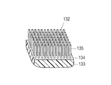
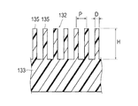
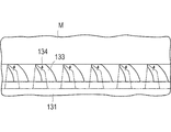
- FIG. 2 is a cross-sectional view taken along line 2-2 in FIG. It is a partial expansion perspective view which shows a part of adhesion part of the biological tissue holding device which concerns on 1st Embodiment. It is sectional drawing which shows the projection part of the biological tissue holding device which concerns on 1st Embodiment. It is sectional drawing which shows the modification of the projection part of the biological tissue holding device which concerns on 1st Embodiment. It is a top view which shows the time of using the biological tissue holding device which concerns on 1st Embodiment.
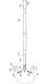
- the biological tissue holding device 100 is a device for holding and treating an organ M (biological tissue) in a body cavity in a state where physiological saline is injected as a liquid into the body cavity. It is.
- Examples of the organ M held by the biological tissue holding device 100 include ovaries and fallopian tubes.
- the holding target is not particularly limited as long as it is a living tissue.
- the biological tissue holding device 100 includes an inner tube 110 (elongate body) in which a first channel 111 and a second channel 112 are formed, and an inner side. And an outer tube 120 (elongate body) through which the tube 110 is inserted.
- An endoscope 140 can be inserted into the first channel 111 of the inner tube 110, and a hollow puncture needle 150 (needle member) can be inserted into the second channel 112.
- a hub portion 113 is provided on the proximal end side of the inner tube 110 so that the endoscope 140 and the puncture needle 150 can be inserted into the first channel 111 and the second channel 112 while maintaining fluid tightness.
- a holding portion 130 is provided at the tip of the inner tube 110 so as to be in contact with the outer surface of the inner tube 110.
- the holding unit 130 includes a plurality (eight in the present embodiment) of plate-like members 131 (expanded portions) arranged in the circumferential direction on the outer surface of the inner tube 110, and the tip side of the plate-like member 131 is the tip of the inner tube 110. And the proximal end side is joined to the distal end of the outer tube 120.
- the plate-like member 131 is thinner from the proximal end side toward the distal end side, and the bending rigidity is lower toward the distal end side. Therefore, when the outer tube 120 is moved to the distal end side with respect to the inner tube 110 as shown in FIG.
- each plate-like member 131 is curved outward and tilted to the distal end side having low rigidity and opened to the distal end side. Deforms into a funnel shape.
- the lock mechanism which can fix the positional relationship with the inner tube 110 in the state which moved the outer tube 120 may be provided separately.
- an adhesive portion 132 is provided on the tip side of the center portion, that is, on the radially outer side of the surface facing the tip side in a state bent in a funnel shape.
- a protruding base 133 that protrudes from the outer surface of the plate-like member 131 is formed on the bonding portion 132.
- a protrusion forming surface 134 that is inclined with respect to the outer surface of the plate-like member 131 is formed on the upper portion of the protruding base 133.
- the projection forming surface 134 is formed so as to be inclined with respect to the outer surface of the plate-like member 131 from the distal end side to the proximal end side of the device.
- a plurality of nano-order fine protrusions 135 are formed to protrude.
- the adhesive portion 132 is formed on the projection forming surface 134 that is inclined with respect to the outer surface of the plate-like member 131, it is peeled off from one side of the projection forming surface 134 when it is peeled off. By applying force from a predetermined direction, it can be easily peeled off.
- the inclination angle of the projection forming surface 134 of the protruding base 133 with respect to the outer surface of the plate-like member 131 is appropriately set and is not particularly limited, but is, for example, 5 to 45 °, and more preferably 20 to 30. °.
- the height of the protruding base 133 is appropriately set and is not particularly limited, but is, for example, 1 to 50 ⁇ m, and more preferably 10 to 30 ⁇ m.
- the area of one protrusion forming surface 134 is appropriately set and is not particularly limited. For example, the area is 1 ⁇ m 2 to 50 ⁇ m 2 , and more preferably 10 ⁇ m 2 to 25 ⁇ m 2 .
- the number of protrusions 135 is 1 to 10 6 per 100 ⁇ m 2 , more preferably 20 to 30 per 1 ⁇ m 2 .
- the arrangement pattern of the protruding base 133 is not particularly limited, and is regularly arranged in the present embodiment, but may be irregularly arranged.
- the protrusion 135 is formed in a columnar shape (in this embodiment, a cylindrical shape).
- the maximum outer diameter D of the protrusion 135 is 5 nm to 10 ⁇ m, and more preferably 0.1 ⁇ m to 0.5 ⁇ m.
- the height H of the protrusion 135 is 1 ⁇ m to 500 ⁇ m, and more preferably 10 ⁇ m to 50 ⁇ m.
- the pitch P of the protrusions 135 is 0 ⁇ m to 1 ⁇ m, and more preferably 0.05 ⁇ m to 0.5 ⁇ m.
- said maximum outer diameter represents the length of the longest site
- One or more protrusions 135 are formed per 100 ⁇ m 2 , and more preferably, 50 or more are formed per 100 ⁇ m 2 . If the projection 135 has the shape and dimensions as described above, it is possible to exert an adhesive force by van der Waals force in both gas and liquid.
- the arrangement pattern of the protrusions 135 is not particularly limited and is regularly arranged in the present embodiment, but may be irregularly arranged.
- the protrusion 135 is formed to extend perpendicularly from the protrusion formation surface 134 in this embodiment, but may be formed to be inclined with respect to the protrusion formation surface 134 as in another example shown in FIG.
- the inclination angle X can be 0 to 60 degrees, and preferably 0 to 30 degrees. Note that the inclination direction and the inclination angle may differ depending on the protrusion 135.
- the protrusion 135 is not limited to a cylindrical shape, and may be a columnar shape having a polygonal cross section, for example.
- the protrusion 135 may not necessarily have the same cross section from the base end portion connected to the substrate 22 to the front end portion.
- the cross section of the front end portion is made larger or smaller than the base end portion. You can also.
- the protruding base 133 may be formed integrally with the plate member 131 or may be formed by bonding another member to the outer surface of the plate member 131 by adhesion or the like.
- thermoplastic resin that is a general plastic, a thermosetting resin such as rubber, or a heat-crosslinkable resin
- a thermoplastic resin that is a general plastic
- a thermosetting resin such as rubber
- a heat-crosslinkable resin can be used.
- polyesters such as polyethylene terephthalate and polybutylene terephthalate, polyester elastomers using these as hard segments, polyolefins such as polyethylene and polypropylene, polyolefin elastomers, copolymer polyolefins using metallocene catalysts, polychlorinated Vinyl-based polymers such as vinyl, PVDC, PVDF, polyamides and polyamide elastomers (PAE) including nylon, polyimide, polystyrene, SEBS resin, polyurethane, polyurethane elastomer, ABS resin, acrylic resin, polyarylate, polycarbonate, polyoxymethylene (POM) ), Polyvinyl alcohol (PVA), fluororesin (ETFE
- the inner tube 110 and the outer tube 120 are required to have a certain degree of rigidity so that the plate-like member 131 can be deformed.
- a resin material similar to the plate member 131 described above, a metal such as stainless steel, or the like can be applied as a constituent material of the inner tube 110 and the outer tube 120.
- the constituent material of the protrusion 135 is not particularly limited, and for example, a resin material similar to that of the plate member 131 described above, a carbon nanotube formed by bottom-up, or the like can be applied.
- a hole-shaped fine pattern 11 of the order of several hundred nm is formed on a polymethyl methacrylate resin (PMMA) supported on a silicon wafer by electron beam lithography to produce a mold 10 (see FIG. 10).
- PMMA polymethyl methacrylate resin
- the shape of the fine pattern 11 is determined so as to coincide with the shape obtained by transferring the protrusion 135 of the protrusion forming surface 134 to be manufactured.
- the resin material described above as the material of the protrusion 135 is dissolved in a liquid so as to be 0.001 to 1% by weight to obtain a sol phase.
- a liquid chloroform or the like can be applied.
- the surface of the mold 10 on which the fine pattern 11 is formed is horizontal upward, and as shown in FIG. 11, the sol-phase material is poured into the mold 10, and the material is made into the fine pattern 11. Further, it is poured by a thickness corresponding to the substrate 22 having a predetermined thickness. Thereafter, the mold 10 is heated to room temperature to 40 degrees to volatilize the liquid and solidify the material. Further, when the material is thermoplastic, it is heated and melted, and then poured into the mold 10 and cooled and solidified.
- the solidified material is removed from the mold 10 to obtain a sheet 20 having a plurality of protrusions 135 formed on the substrate 22. Thereafter, the sheet 20 is bonded onto the projection forming surface 134 of the plate-like member 131 manufactured in a separate process, and the projection 135 is provided on the projection forming surface 134.
- the protruding base 133 may be integrally formed simultaneously with the formation of the protruding portion 135.
- a plurality of protrusions 135 can be formed to protrude from each of the plurality of protrusions 25 formed on the substrate 22.
- the protrusions can be conical or pyramidal.
- nanoimprint, soft lithography, and shaping using a fine bit can be applied to processing a pattern of the order of several hundreds of nm. It is preferable to select appropriately according to conditions such as dimensions and materials. If it is a pyramid shape, it can be easily manufactured by forming grooves vertically and horizontally with fine tools.
- a known trocar having an inner needle (not shown) inserted through a separately prepared tubular outer tube 160 is inserted transvaginally and punctured into the Douglas fossa to reach the abdominal cavity. Thereafter, the inner needle is pulled out while leaving the outer tube 160, and physiological saline is injected into the abdominal cavity through the outer tube 160 using a separate water injection mechanism (not shown).
- the endoscope 140 is inserted into the first channel 111 of the biological tissue holding device 100, and the biological tissue holding device 100 is inserted into the outer tube 160.
- the projection forming surface 134 on which the fine projection 135 is formed is inclined, the projection 135 is difficult to adhere to the inner surface of the outer tube 160.
- the inner surface of the outer tube 160 may be covered with a low friction member such as a fluororesin in order to prevent the protrusion 135 from adhering.
- the biological tissue holding device 100 is pushed forward to reach the target position.
- the outer tube 120 After reaching the oviduct which is the target organ M, the outer tube 120 is moved to the distal end side with respect to the inner tube 110 while finely adjusting the puncture site to be located in front of the second channel 112. Thereby, as shown in FIG. 6, the plate-shaped member 131 is deformed into a funnel shape.
- the adhesive portion 132 of the plate member 131 is pressed against the oviduct.
- the plate-shaped member 131 gradually contacts the oviduct from the distal end side (the side connected to the inner tube 110) of the bonding portion 132 while finally deforming toward the distal end side while expanding outward, and finally The plate-like member 131 is held so as to wrap the fallopian tube.
- the protruding base 133 is deformed, and the protrusion forming surface 134 formed to be inclined comes into contact with the organ M.
- FIG. 7 the protruding base 133 is deformed, and the protrusion forming surface 134 formed to be inclined comes into contact with the organ M.
- the organ M is attached and held on the bonding portion 132 by van der Waals force. Since the pressing force may be smaller than the pressing force for puncturing or the like, even the organ M suspended in the liquid can be attached. Furthermore, since it is pressed so as to wrap, it is easy to generate a pressing force even for a floating organ M. Since the plate-like member 131 is deformed in a funnel shape and is bonded so as to wrap the organ M, it can be held without applying a load to the organ M as much as possible.
- the puncture needle 150 is inserted into the second channel 112 of the biological tissue holding device 100, and the puncture position is confirmed by the endoscope 140 to puncture the organ M.
- the organ M is held by the holding unit 130 and is held by the holding unit 130 at a plurality of positions on the outer periphery of the puncture needle 150, puncture can be performed at an accurate position, and safety is improved. To do.
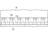
- the secretory fluid staying inside the organ M is sucked and discharged through the hollow puncture needle 150. Thereafter, the puncture needle 150 is retracted and pulled out from the organ M. Then, the outer tube 120 is retracted with respect to the inner tube 110, and the plate-like member 131 deformed into a funnel shape is returned to its original shape. When the plate-like member 131 is returned to the original shape, the plate-like member 131 is gradually separated from the organ M from the radially outer side (side connected to the outer tube 120) of the adhesive portion 132 of the spread plate-like member 131. And since the low side of the protrusion base 133 is located in the radial direction outer side, as shown in FIG.
- the protrusion base 133 is pulled apart from the low side. Therefore, the projection forming surface 134 of the protruding base 133 is separated from one direction, the projection 135 can be easily separated, and can be separated without applying a load to the organ M as much as possible.
- the bonding portion 132 can be bonded and separated without applying a load to the organ M as much as possible. Therefore, if the bonding portion 132 cannot be held at a desired position when bonding, no treatment (puncture) is performed. It is possible to hold it apart from each other.
- the biological tissue holding device 100 is pulled out from the mantle tube 160 and the physiological saline in the abdominal cavity is discharged through the mantle tube 160, and then the mantle tube 160 is also removed, and the procedure is completed.
- the outer tube 120 to be inserted into the body cavity and the holding portion 130 provided at the distal end portion of the inner tube 110 are formed with the protrusion 135 that is bonded to the organ M by van der Waals force. Therefore, the holding unit 130 can hold the organ M in a liquid containing water in the body cavity, and the held organ M can be observed, treated, or moved. Furthermore, since holding is performed by van der Waals force, a large holding force can be generated even if the pressing force is small, and the influence on the organ M can be reduced.
- the holding unit 130 includes the plate-like member 131 that can be deformed or moved by an operation on the proximal side of the outer tube 120 and the inner tube 110, the organ M is deformed or moved after being inserted into the body cavity. Can be held.
- maintenance part 130 is provided with the expansion part which deform
- first channel 111 and the second channel 112 are formed inside the inner tube 110, devices for observing and treating the endoscope 140, the puncture needle 150, and the like can be inserted.
- the hollow puncture needle 150 that can move in the second channel 112 is provided, the held organ M can be punctured.
- the biological tissue holding device 200 according to the second embodiment of the present invention is different from the biological tissue holding device 100 according to the first embodiment only in the structure of the holding unit 230.
- symbol is attached
- the holding unit 230 of the biological tissue holding device 200 includes a mesh member 231 formed in a mesh shape with a plurality of wires.
- the mesh member 231 is knitted with a mesh on the distal end side that is rougher than the proximal end side of the device, and the bending rigidity decreases toward the distal end side.
- FIG. 14B when the outer tube 120 is moved to the distal end side with respect to the inner tube 110, each wire is curved outward and tilted toward the distal end side having low rigidity, toward the distal end side. It transforms into an open funnel shape.
- the material of the wire constituting the mesh member 231 is not particularly limited as long as it is elastically deformable.
- stainless steel or a superelastic alloy for example, Ni—Ti alloy
- the protruding portion 135 is formed on the protruding surface 134 of the protruding base 133 that is arranged to protrude from the mesh member 231. Further, in order to increase the area of the bonding portion 232, a film-like member that can be expanded together with the mesh-like member 231 is provided on the mesh-like member 231, and the projecting base 133 and the protrusion 135 are formed on the film-like member. May be.
- the film-like member can be expanded integrally with the mesh member 231 by spreading elastically or expanding from a folded state.
- a silicon rubber-based material such as polydimethylsiloxane (PDMS) is elastically spread, and polytetrafluoroethylene (PTFE) is knitted with nanofibers as it spreads from a folded state.
- PDMS polydimethylsiloxane
- PTFE polytetrafluoroethylene
- a non-woven fabric or a porous membrane can be applied.
- the organ M can be held by van der Waals force in a liquid containing water, and held without applying a load to the organ M as much as possible. Can be observed, treated, or moved.
- the biological tissue holding device 300 includes an inner tube 310 in which a first channel 311 and a second channel 312 are formed, and an outer tube through which the inner tube 310 is inserted. 320.
- the endoscope 140 can be inserted into the first channel 311 of the inner tube 310, and the hollow puncture needle 150 can be inserted into the second channel 312.
- a hub portion 313 into which the endoscope 140 and the puncture needle 150 can be inserted is provided on the proximal end side of the inner tube 310.
- maintenance part 330 extended in a radial direction outer side is provided in the front-end
- the holding unit 330 includes an annular member 331 formed in an annular shape by an elastically deforming wire, and a plurality (four in the present embodiment) of the annular members 331 are provided in the circumferential direction at the distal end of the inner tube 310. .
- the annular member 331 When the outer tube 320 is moved in the distal direction with respect to the inner tube 310 and the outer tube 320 covers the annular member 331, the annular member 331 is elastically deformed and fits inside the outer tube 320. When moved in the end direction, the annular member 331 expands elastically.
- a lock mechanism that can fix the positional relationship with the inner tube 310 while the outer tube 320 is moved may be provided.
- An adhesive portion 332 is formed at a radially outer portion of the surface facing the distal end when the annular member 331 spreads.
- a protruding base 333 that protrudes from the outer surface of the plate-like member is formed on the bonding portion 332.
- a protrusion forming surface 334 inclined with respect to the outer surface of the annular member 331 is formed on the upper portion of the protruding base 333.
- the projection forming surface 334 is formed so as to be inclined with respect to the outer surface of the annular member 331 from the distal end side toward the proximal end side, and the nano-order fine projection portion 135 is formed on the projection forming surface 334.
- a plurality of protrusions are formed.
- the biological tissue holding device 300 is inserted into a body cavity with the holding portion 330 covered by the outer tube 320.
- the outer tube 320 is moved to the proximal end side with respect to the inner tube 310, and the annular member 331 is restored to an expanded shape.
- the adhesion part 332 which has the projection part 135 is adhere
- the organ M is held by the holding unit 330.
- the puncture needle 150 is inserted into the second channel 312 of the biological tissue holding device 300, and the puncture position is confirmed by the endoscope 140 to puncture the organ M.
- the organ M is held by the holding unit 330 and is held by the holding unit 330 at a plurality of positions on the outer periphery of the puncture needle 150, the organ M is held with high accuracy and punctured at an accurate position. Can improve safety.
- the secretory fluid retained in the organ M is aspirated through the hollow puncture needle 150 and discharged. Thereafter, the puncture needle 150 is retracted and pulled out from the organ M.
- the protrusion forming surface 334 is formed so as to be inclined with respect to the outer surface of the annular member 331 from the distal end side toward the proximal end side. Therefore, it is pulled away from one side, and can be separated without giving a load to the organ M as much as possible.
- the outer tube 320 is moved to the tip side with respect to the inner tube 310, and the annular member 331 is accommodated in the outer tube 320. Thereafter, the biological tissue holding device 300 is pulled out from the mantle tube 160, the physiological saline in the abdominal cavity is discharged through the mantle tube 160, and the mantle tube 160 is also taken out to complete the procedure.
- the annular member 331 provided in the holding unit 330 can hold, observe, treat, or move the organ M so that the organ M is not loaded as much as possible.
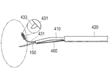
- the biological tissue holding device 400 is inserted with the inner tube 410 in which the first channel 411 is formed, the inner tube 410 and the endoscope 140. And an outer tube 420 in which a second channel 412 is formed.
- a long holding portion 430 and a hollow puncture needle 150 can be liquid-tightly inserted into the first channel 411 of the inner tube 410.
- a hub portion 423 into which the endoscope 140 and the inner tube 410 can be inserted is provided on the proximal end side of the outer tube 420.
- the holding portion 430 includes a wire member 431 that is an elastically deformable wire and a spherical portion 436 provided at the tip of the wire member 431 in order to reduce the influence on the living body.
- An adhesive portion 432 is formed on the outer peripheral surface.
- a protruding base 433 that protrudes from the outer surface of the wire member 431 is formed on the bonding portion 432.
- a protrusion forming surface 434 that is inclined with respect to the outer surface of the wire member 431 is formed on the upper portion of the protruding base 433.
- the protrusion forming surface 434 is formed so as to be inclined with respect to the outer surface of the line member 431 from the distal end side toward the proximal end side, and the nano-order fine protrusion portion 135 is formed on the protrusion forming surface 434. A plurality of protrusions are formed.
- the biological tissue holding device 400 is inserted into a body cavity in a state where the puncture needle 150 and the holding unit 430 are accommodated in the inner tube 410 and the endoscope 140 and the inner tube 410 are accommodated inside the outer tube 420.
- the inner tube 410 is projected from the outer tube 420 to the distal end side while observing with the endoscope 140. Thereafter, as shown in FIG. 18, the wire member 431 of the holding portion 430 is protruded from the inner tube 410, and the wire member 431 is pressed against the organ M.
- the wire member 431 is deformed along the living body while being curved, and the bonding portion 432 having the protrusion 135 on the protrusion forming surface 434 is bonded to the organ M.
- the organ M is held by the holding unit 430.
- the puncture needle 150 is inserted into the first channel 411 of the biological tissue holding device 400, and the puncture position is confirmed by the endoscope 140 to puncture the organ M.
- puncture can be performed at an accurate position, and safety is improved.
- the secretory fluid retained in the organ M is sucked and discharged through the hollow puncture needle 150, and the puncture needle 150 is retracted and pulled out from the organ M.
- the protrusion forming surface 434 is inclined so as to become lower with respect to the outer surface of the line member 431 from the distal end side toward the proximal end side. Therefore, it is separated from one side (base end side), and can be separated without giving a load to the organ M as much as possible.
- the holding portion 430 is accommodated in the inner tube 410, the inner tube 410 is accommodated in the outer tube 420, the biological tissue holding device 400 is pulled out from the outer tube 160, and physiological saline in the abdominal cavity is removed from the outer tube 160. After being discharged, the outer tube 160 is also removed, and the procedure is completed.
- the living tissue can be easily held only by pressing the wire member 431, the workability is excellent.
- the line member 431 makes it possible to hold, observe, treat, or move the organ M so as not to apply a load to the organ M as much as possible.
- FIG. 19 is a modification of the fourth embodiment, but the inner tube 410 may protrude from an opening provided on the side surface of the outer tube 420. In this way, the inner tube 410 can be protruded by avoiding the endoscope 140 in which the solid-state imaging device 141 is provided and the tip portion is large, and the outer tube 420 is further reduced in diameter to reduce the load on the living body. Can be reduced.
- FIG. 20 shows another modification of the fourth embodiment.
- the inner tube 410 can be bent to change the orientation of the endoscope 140 and the puncture needle 150, and reach a region that is not normally reachable. Observation and treatment can be performed.
- the pulling wire 460 extends from the distal end of the inner tube 410 to be fixed to a proximal end side by a predetermined length, and then is introduced into the inner tube 410 from a hole (not shown) formed on the side surface of the inner tube 410. May be.
- the biological tissue holding device 500 according to the fifth embodiment is different from the fourth embodiment only in that the wire member 531 of the holding portion 530 is annular as shown in FIGS. And the adhesion part 532 is formed in the outer surface at the front end side of the wire member 531.
- a protruding base 533 that protrudes from the outer surface of the wire member 531 is formed on the bonding portion 532, and a protrusion forming surface 534 that is inclined with respect to the outer surface of the line member 531 is formed on the upper portion of the protruding base 533.
- the protrusion forming surface 534 is formed so as to be inclined with respect to the outer surface of the line member 531 from the distal end side toward the proximal end side.
- a nano-order fine protrusion portion 135 is formed on the protrusion forming surface 534.
- a plurality of protrusions are formed.
- the wire member 531 of the holding portion 530 protrudes from the inner tube 410 and the adhesive portion 532 of the wire member 531 is pressed against the organ M.
- the wire member 531 of the holding portion 530 protrudes from the inner tube 410 and the adhesive portion 532 of the wire member 531 is pressed against the organ M.
- the present invention is not limited to the above-described embodiments, and various modifications can be made by those skilled in the art within the technical idea of the present invention.
- the endoscope 140 and the puncture needle 150 are not necessarily provided, and the channel into which the endoscope 140 and the puncture needle 150 are inserted is not necessarily provided.
- attach is not limited to the structure which adhere
- an adhesive force (adhesive force) is exhibited in the adhesive part in the liquid containing water.
- An adhesive (adhesive) may be applied.
- a pressure-sensitive adhesive include 3,4-dihydroxy-L-phenylalanine (dopamine, DOPA), an adhesive peptide having a catechol group, and derivatives thereof, and polymers and copolymers thereof. Can be mentioned.
- polysaccharides such as dextran, dextrin, and derivatives thereof may be applied.
- Biological tissue holding device 110, 310, 410 inner tube, 111, 311, 411 first channel, 112, 312, 412 second channel, 120, 320, 420 outer tube, 130, 230, 330, 430, 530 holder, 131 plate member (expanded part), 132, 232, 332, 432, 532 bonding part, 133, 333, 433, 533 protruding base, 134, 334, 434, 534 projection forming surface, 135 protrusions, 159 puncture needle (needle member), 231 mesh member (expanded portion), 331 annular member (expanded portion), 431, 531 wire members, 460 puller wire, D Maximum outer diameter of protrusion, M organ (living tissue), P Pitch pitch, X Inclination angle of the protrusion.
Abstract
[Problème] L'objet de l'invention est d'obtenir un dispositif pour tenir un tissu vivant, permettant de tenir un tissu vivant tout en appliquant la plus petite charge possible sur un tissu vivant situé dans une cavité corporelle. [Solution] Un dispositif (100) pour tenir un tissu vivant selon l'invention comporte des éléments allongés (110, 120) qui peuvent être insérés dans une cavité corporelle, et des éléments de maintien (130) situés aux extrémités des éléments allongés (110, 120), ces éléments de maintien (130) présentant une force d'adhérence. Le dispositif (100) pour tenir un tissu vivant permet de tenir un tissu vivant à l'aide d'une force d'adhérence dans un liquide contenant de l'eau, à l'intérieur d'une cavité corporelle.
Priority Applications (2)
| Application Number | Priority Date | Filing Date | Title |
|---|---|---|---|
| JP2013507208A JPWO2012132483A1 (ja) | 2011-03-28 | 2012-01-10 | 生体組織保持用デバイス |
| US14/039,058 US20140024887A1 (en) | 2011-03-28 | 2013-09-27 | Device for holding living tissue |
Applications Claiming Priority (2)
| Application Number | Priority Date | Filing Date | Title |
|---|---|---|---|
| JP2011-070306 | 2011-03-28 | ||
| JP2011070306 | 2011-03-28 |
Related Child Applications (1)
| Application Number | Title | Priority Date | Filing Date |
|---|---|---|---|
| US14/039,058 Continuation US20140024887A1 (en) | 2011-03-28 | 2013-09-27 | Device for holding living tissue |
Publications (1)
| Publication Number | Publication Date |
|---|---|
| WO2012132483A1 true WO2012132483A1 (fr) | 2012-10-04 |
Family
ID=46930251
Family Applications (1)
| Application Number | Title | Priority Date | Filing Date |
|---|---|---|---|
| PCT/JP2012/050221 WO2012132483A1 (fr) | 2011-03-28 | 2012-01-10 | Dispositif pour tenir un tissu vivant |
Country Status (3)
| Country | Link |
|---|---|
| US (1) | US20140024887A1 (fr) |
| JP (1) | JPWO2012132483A1 (fr) |
| WO (1) | WO2012132483A1 (fr) |
Cited By (4)
| Publication number | Priority date | Publication date | Assignee | Title |
|---|---|---|---|---|
| WO2015163042A1 (fr) * | 2014-04-21 | 2015-10-29 | オリンパス株式会社 | Sonde d'observation grossissante |
| JP2016501083A (ja) * | 2012-11-29 | 2016-01-18 | マサチューセッツ インスティテュート オブ テクノロジー | 表面マイクロパターニングおよび反応性化学の組み合わせを含む接着物品ならびにそれを製造および使用する方法 |
| CN106333717A (zh) * | 2016-10-21 | 2017-01-18 | 中国人民解放军第二军医大学 | 磨痂器 |
| JP2017534474A (ja) * | 2014-11-11 | 2017-11-24 | ザ・チャールズ・スターク・ドレイパー・ラボラトリー・インコーポレイテッド | 2次元および3次元構造物内にナノスケールおよびマイクロスケール物体をアセンブリする方法 |
Families Citing this family (9)
| Publication number | Priority date | Publication date | Assignee | Title |
|---|---|---|---|---|
| WO2014201380A1 (fr) | 2013-06-14 | 2014-12-18 | Altai Medical Technologies | Filtre de veine cave inférieure et systèmes de retrait |
| JP6601501B2 (ja) | 2014-11-04 | 2019-11-13 | ニプロ株式会社 | 海綿骨を圧縮するための長手方向膨張要素が内部に設けられたカテーテルデバイス |
| US10278804B2 (en) | 2014-12-12 | 2019-05-07 | Avantec Vascular Corporation | IVC filter retrieval systems with releasable capture feature |
| EP3229729B1 (fr) | 2014-12-12 | 2023-03-15 | Avantec Vascular Corporation | Systèmes de récupération de filtre de veine cave inférieure avec éléments de support interposés |
| US9931129B2 (en) * | 2015-03-19 | 2018-04-03 | Gyrus Acmi, Inc. | Small fragment retrieval device |
| FR3057758B1 (fr) * | 2016-10-20 | 2022-01-28 | Stsat Ag | Systeme pour extraire la substance thromboembolique presente dans un vaisseau sanguin |
| CN110167482A (zh) | 2016-12-22 | 2019-08-23 | 阿万泰血管公司 | 具有系绳的用于取回系统的系统、装置和方法 |
| DE102017131344A1 (de) * | 2017-12-27 | 2019-06-27 | Leibniz-Institut Für Neue Materialien Gemeinnützige Gmbh | Formkörper mit strukturierter Oberfläche zur reversiblen Adhäsion |
| EP3813739A4 (fr) | 2018-06-29 | 2022-04-13 | Avantec Vascular Corporation | Systèmes et procédés pour implants et dispositifs de déploiement |
Citations (4)
| Publication number | Priority date | Publication date | Assignee | Title |
|---|---|---|---|---|
| JPH01158931A (ja) * | 1987-09-01 | 1989-06-22 | Terumo Corp | カテーテルチューブ |
| JPH05237193A (ja) * | 1991-12-02 | 1993-09-17 | Everest Medical Corp | 電気外科用器具 |
| JPH07255853A (ja) * | 1994-02-16 | 1995-10-09 | Novoste Corp | 電気生理学位置決めカテーテル |
| JP2009539575A (ja) * | 2006-06-14 | 2009-11-19 | ボエッジ メディカル, インコーポレイテッド | 経中隔アクセスのための可視化装置および方法 |
Family Cites Families (17)
| Publication number | Priority date | Publication date | Assignee | Title |
|---|---|---|---|---|
| CA2197614C (fr) * | 1996-02-20 | 2002-07-02 | Charles S. Taylor | Instruments chirurgicaux et procedes de stabilisation du coeur palpitant en cours de pontage aortocoronarien |
| US6800080B1 (en) * | 1996-05-03 | 2004-10-05 | Scimed Life Systems, Inc. | Medical retrieval device |
| US8070761B2 (en) * | 2003-04-10 | 2011-12-06 | Boston Scientific Scimed, Inc. | Vessel occluding material extractor |
| US20050038498A1 (en) * | 2003-04-17 | 2005-02-17 | Nanosys, Inc. | Medical device applications of nanostructured surfaces |
| US7074294B2 (en) * | 2003-04-17 | 2006-07-11 | Nanosys, Inc. | Structures, systems and methods for joining articles and materials and uses therefor |
| US8388630B2 (en) * | 2003-09-18 | 2013-03-05 | Boston Scientific Scimed, Inc. | Medical retrieval devices and methods |
| US20050119640A1 (en) * | 2003-10-03 | 2005-06-02 | The Regents Of The University Of California | Surgical instrument for adhering to tissues |
| US20080280085A1 (en) * | 2006-06-25 | 2008-11-13 | Oren Livne | Dynamically Tunable Fibrillar Structures |
| US20100228082A1 (en) * | 2006-08-07 | 2010-09-09 | Koninklijke Philips Electronics N.V. | Device, system and method for interacting with a cell or tissue in a body |
| EP2063789A2 (fr) * | 2006-10-03 | 2009-06-03 | Arsenal Medical, Inc. | Articles et procédés pour la réparation de tissus |
| US20080269774A1 (en) * | 2006-10-26 | 2008-10-30 | Chestnut Medical Technologies, Inc. | Intracorporeal Grasping Device |
| JP2009117440A (ja) * | 2007-11-02 | 2009-05-28 | Creative Technology:Kk | クリーニングウエハ |
| JP5185668B2 (ja) * | 2008-03-26 | 2013-04-17 | 東京医研株式会社 | 止血装置 |
| US8398909B1 (en) * | 2008-09-18 | 2013-03-19 | Carnegie Mellon University | Dry adhesives and methods of making dry adhesives |
| JP2010125226A (ja) * | 2008-11-28 | 2010-06-10 | Olympus Corp | カテーテル |
| US8986291B2 (en) * | 2008-12-01 | 2015-03-24 | Percutaneous Systems, Inc. | Methods and systems for capturing and removing urinary stones from body cavities |
| US20120052234A1 (en) * | 2010-08-30 | 2012-03-01 | Sriram Natarajan | Adhesive structure with stiff protrusions on adhesive surface |
-
2012
- 2012-01-10 JP JP2013507208A patent/JPWO2012132483A1/ja active Pending
- 2012-01-10 WO PCT/JP2012/050221 patent/WO2012132483A1/fr active Application Filing
-
2013
- 2013-09-27 US US14/039,058 patent/US20140024887A1/en not_active Abandoned
Patent Citations (4)
| Publication number | Priority date | Publication date | Assignee | Title |
|---|---|---|---|---|
| JPH01158931A (ja) * | 1987-09-01 | 1989-06-22 | Terumo Corp | カテーテルチューブ |
| JPH05237193A (ja) * | 1991-12-02 | 1993-09-17 | Everest Medical Corp | 電気外科用器具 |
| JPH07255853A (ja) * | 1994-02-16 | 1995-10-09 | Novoste Corp | 電気生理学位置決めカテーテル |
| JP2009539575A (ja) * | 2006-06-14 | 2009-11-19 | ボエッジ メディカル, インコーポレイテッド | 経中隔アクセスのための可視化装置および方法 |
Cited By (5)
| Publication number | Priority date | Publication date | Assignee | Title |
|---|---|---|---|---|
| JP2016501083A (ja) * | 2012-11-29 | 2016-01-18 | マサチューセッツ インスティテュート オブ テクノロジー | 表面マイクロパターニングおよび反応性化学の組み合わせを含む接着物品ならびにそれを製造および使用する方法 |
| WO2015163042A1 (fr) * | 2014-04-21 | 2015-10-29 | オリンパス株式会社 | Sonde d'observation grossissante |
| JP5945636B2 (ja) * | 2014-04-21 | 2016-07-05 | オリンパス株式会社 | 拡大観察プローブ |
| JP2017534474A (ja) * | 2014-11-11 | 2017-11-24 | ザ・チャールズ・スターク・ドレイパー・ラボラトリー・インコーポレイテッド | 2次元および3次元構造物内にナノスケールおよびマイクロスケール物体をアセンブリする方法 |
| CN106333717A (zh) * | 2016-10-21 | 2017-01-18 | 中国人民解放军第二军医大学 | 磨痂器 |
Also Published As
| Publication number | Publication date |
|---|---|
| US20140024887A1 (en) | 2014-01-23 |
| JPWO2012132483A1 (ja) | 2014-07-24 |
Similar Documents
| Publication | Publication Date | Title |
|---|---|---|
| WO2012132483A1 (fr) | Dispositif pour tenir un tissu vivant | |
| US9555217B2 (en) | Catheter | |
| Sameoto et al. | Recent advances in the fabrication and adhesion testing of biomimetic dry adhesives | |
| Chen et al. | Rapid fabrication of microneedles using magnetorheological drawing lithography | |
| US7691307B2 (en) | Adhesive microstructure and method of forming same | |
| CA2796196C (fr) | Matrice de micro-aiguilles composite comprenant des nanostructures | |
| US9138233B2 (en) | Apparatus and method for tissue adhesion | |
| US20070282374A1 (en) | Tissue attachment device, system, and method | |
| JP2022027860A (ja) | 押し潰し可能なチューブ状ダイアフラムを有する医療手順用イントロデューサシースバルブ | |
| WO2010033725A2 (fr) | Appareil et procédé pour l’adhérence d’un tissu | |
| AU2014292687B2 (en) | Medical instrument and application thereof | |
| US20140369802A1 (en) | Methods, apparatuses, and systems for micromanipulation with adhesive fibrillar structures | |
| WO2012170068A2 (fr) | Micro-actionneurs sans fil et procédés de commande | |
| JP6081930B2 (ja) | カテーテル | |
| US20150005665A1 (en) | Cytology brush devices and methods of use | |
| US20140025104A1 (en) | Biological adhesive sheet and device for attaching biological adhesive sheet | |
| US8177752B2 (en) | Medical tube set | |
| JP2009183698A (ja) | 器具保持器 | |
| JP5568234B2 (ja) | 針状体および針状体製造方法 | |
| Gopalakrishnaiah et al. | Microfluidic drive for flexible brain implants | |
| JP2019024732A (ja) | 生体操作具 | |
| JP2008054836A (ja) | バルーンダイレータ及びバルーンダイレータシステム | |
| JP2003265612A (ja) | バルーンカテーテル | |
| JP2017169660A (ja) | 医療用チューブの製造方法および製造装置 | |
| Luu | Processing PDMS Gecko Tape Using Isopore Filters and Silicon Wafer Templates |
Legal Events
| Date | Code | Title | Description |
|---|---|---|---|
| 121 | Ep: the epo has been informed by wipo that ep was designated in this application |
Ref document number: 12764543 Country of ref document: EP Kind code of ref document: A1 |
|
| ENP | Entry into the national phase |
Ref document number: 2013507208 Country of ref document: JP Kind code of ref document: A |
|
| NENP | Non-entry into the national phase |
Ref country code: DE |
|
| 122 | Ep: pct application non-entry in european phase |
Ref document number: 12764543 Country of ref document: EP Kind code of ref document: A1 |