WO2012132077A1 - 誘導加熱装置 - Google Patents
誘導加熱装置 Download PDFInfo
- Publication number
- WO2012132077A1 WO2012132077A1 PCT/JP2011/074171 JP2011074171W WO2012132077A1 WO 2012132077 A1 WO2012132077 A1 WO 2012132077A1 JP 2011074171 W JP2011074171 W JP 2011074171W WO 2012132077 A1 WO2012132077 A1 WO 2012132077A1
- Authority
- WO
- WIPO (PCT)
- Prior art keywords
- induction heating
- heating apparatus
- cooling
- shielding plate
- magnetically permeable
- Prior art date
- Legal status (The legal status is an assumption and is not a legal conclusion. Google has not performed a legal analysis and makes no representation as to the accuracy of the status listed.)
- Ceased
Links
Images



Classifications
-
- H—ELECTRICITY
- H10—SEMICONDUCTOR DEVICES; ELECTRIC SOLID-STATE DEVICES NOT OTHERWISE PROVIDED FOR
- H10P—GENERIC PROCESSES OR APPARATUS FOR THE MANUFACTURE OR TREATMENT OF DEVICES COVERED BY CLASS H10
- H10P72/00—Handling or holding of wafers, substrates or devices during manufacture or treatment thereof
- H10P72/04—Apparatus for manufacture or treatment
- H10P72/0431—Apparatus for thermal treatment
- H10P72/0434—Apparatus for thermal treatment mainly by convection
-
- H—ELECTRICITY
- H10—SEMICONDUCTOR DEVICES; ELECTRIC SOLID-STATE DEVICES NOT OTHERWISE PROVIDED FOR
- H10P—GENERIC PROCESSES OR APPARATUS FOR THE MANUFACTURE OR TREATMENT OF DEVICES COVERED BY CLASS H10
- H10P95/00—Generic processes or apparatus for manufacture or treatments not covered by the other groups of this subclass
- H10P95/90—Thermal treatments, e.g. annealing or sintering
-
- C—CHEMISTRY; METALLURGY
- C23—COATING METALLIC MATERIAL; COATING MATERIAL WITH METALLIC MATERIAL; CHEMICAL SURFACE TREATMENT; DIFFUSION TREATMENT OF METALLIC MATERIAL; COATING BY VACUUM EVAPORATION, BY SPUTTERING, BY ION IMPLANTATION OR BY CHEMICAL VAPOUR DEPOSITION, IN GENERAL; INHIBITING CORROSION OF METALLIC MATERIAL OR INCRUSTATION IN GENERAL
- C23C—COATING METALLIC MATERIAL; COATING MATERIAL WITH METALLIC MATERIAL; SURFACE TREATMENT OF METALLIC MATERIAL BY DIFFUSION INTO THE SURFACE, BY CHEMICAL CONVERSION OR SUBSTITUTION; COATING BY VACUUM EVAPORATION, BY SPUTTERING, BY ION IMPLANTATION OR BY CHEMICAL VAPOUR DEPOSITION, IN GENERAL
- C23C16/00—Chemical coating by decomposition of gaseous compounds, without leaving reaction products of surface material in the coating, i.e. chemical vapour deposition [CVD] processes
- C23C16/44—Chemical coating by decomposition of gaseous compounds, without leaving reaction products of surface material in the coating, i.e. chemical vapour deposition [CVD] processes characterised by the method of coating
- C23C16/46—Chemical coating by decomposition of gaseous compounds, without leaving reaction products of surface material in the coating, i.e. chemical vapour deposition [CVD] processes characterised by the method of coating characterised by the method used for heating the substrate
Definitions
- the present invention relates to an induction heating apparatus, and particularly to an induction heating apparatus suitable for controlling the temperature of an object to be heated when a semiconductor substrate having a large diameter is heat-treated.
- Patent Document 1 includes a chamber constituting a process chamber and an induction heating coil wound around a core constituting a magnetic pole.
- the induction heating apparatus having such a configuration, the magnetic flux generated through the magnetic pole is generated in parallel with the mounting direction of the semiconductor substrate that is the object to be heated disposed in the chamber. For this reason, even when a metal film or the like is formed on the surface of the semiconductor substrate, magnetic flux is not input in a direction intersecting with the metal film, and the substrate may be directly heated by induction heating. No. For this reason, the temperature distribution in the substrate surface does not vary.
- the metal film is certainly directly heated by induction heating even in a semiconductor substrate or the like whose surface is coated with the metal film. There is no fear.
- the partition walls constituting the chamber are made of a heat-resistant metal such as aluminum, so that the magnetic flux generated from the magnetic poles reaches the susceptor that is the induction heating member. It is necessary to form an opening in a part of this.
- the inside of the chamber cannot be evacuated. Further, when the opening is sealed with a magnetic pole in order to seal the chamber, there is a risk that contamination will occur in the chamber.
- the opening provided in the chamber usually has characteristics such as vacuum strength, magnetic flux permeability, heat resistance, low thermal expansion coefficient, low thermal conductivity, and resistance to thermal shock, and there is no risk of contamination. Quartz was to be placed.
- an object of the present invention is to provide an induction heating apparatus that can efficiently heat an induction heating member while realizing prevention of heating of magnetic poles arranged outside the chamber.
- an induction heating apparatus comprises a magnetic permeability that shields a chamber constituting a process chamber and an opening provided on an outer periphery of the chamber and a partition member constituting the chamber.
- An induction heating device having an induction heating coil or an induction heating coil magnetic pole arranged close to the shielding plate is provided with a cooling plate closely or close to the magnetically permeable shielding plate for cooling the magnetically permeable shielding plate. It is characterized by that.
- This cooling plate is required to have magnetic permeability, heat ray shielding (high emissivity), and high thermal conductivity.
- the cooling plate may be made of ceramic. This is because with such a configuration, the cooling plate can block the radiant heat from the susceptor.
- the induction heating apparatus having the above-described characteristics, it is preferable to provide a gap between the cooling plate and the magnetic pole.
- the heat of the magnetically permeable shielding plate transmitted through the cooling plate is not directly transmitted to the magnetic pole by heat transfer, and the effect of preventing the heating of the magnetic pole (temperature rise suppression) is achieved. Can be increased.
- the induction heating apparatus having the above-described characteristics may be provided with a cooling pipe through which a refrigerant for cooling the cooling plate is inserted. It is because it becomes possible to cool a cooling plate constantly with a refrigerant
- the induction heating apparatus having the above-described features includes a pair of induction heating coils or induction heating coil magnetic poles having different polarities, and the cooling pipe includes both the pair of induction heating coils or induction heating coil magnetic poles. It is good to arrange so that it may surround.
- the induced current (eddy current) generated by the magnetic flux applied to the cooling pipe is offset or partially offset, thereby preventing the cooling effect from being reduced by heating the cooling pipe itself. Can do.
- the cooling pipe is used for the induction heating coil or the induction heating coil over the entire assembly. It may be arranged so as to surround the magnetic pole.
- the magnetically permeable shielding plate may be made of quartz. This is because quartz has vacuum resistance, magnetic flux permeability, heat resistance, low thermal expansion, low thermal conductivity, and thermal shock resistance.
- the induction heating coil includes a tubular member through which a refrigerant can be inserted and a twisted wire made of a plurality of wire rods, and the tubular member is disposed on the tip side of the magnetic pole. It is good to set it as the structure which arrange
- the induction heating apparatus having the above-described characteristics, it is possible to efficiently heat the induction heating member while realizing the prevention of heating of the magnetic pole arranged outside the chamber.
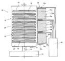
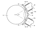
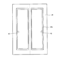
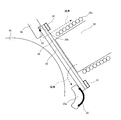
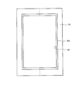
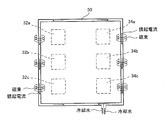
- FIG. 1st Embodiment It is a top view which shows the structure of the induction heating apparatus which concerns on 1st Embodiment. It is a figure which shows the structure of the AA cross section in FIG. It is a top view which shows the relationship between the angle of two magnetic poles, and an opening part. It is a figure which shows the front form of the opening part provided in the housing. It is a figure which shows the detail of the assembly
- FIG. 1 is a partial cross-sectional block diagram illustrating a planar configuration of the induction heating apparatus
- FIG. 2 is a block diagram illustrating a cross-section AA in FIG.
- the induction heating apparatus 10 is a batch-type apparatus in which a wafer 60 as a heated object and a susceptor 16 as an induction heating member (heating element) are stacked in multiple stages to perform heat treatment.
- the induction heating apparatus 10 is configured based on a chamber 12, an excitation unit 28 disposed outside the chamber 12, and a power supply unit 40.
- the chamber 12 is a process chamber configured based on the boat 14, the rotary table 18, and the housing 26.
- the boat 14 is configured by stacking a plurality of susceptors 16 on which wafers 60 to be heated are placed in a vertical direction.
- a support member (not shown) is disposed between the susceptors 16 and is configured to maintain a predetermined interval for disposing the wafer 60.
- the support member (not shown) is not affected by the magnetic flux, is preferably made of a member having high heat resistance and a low coefficient of thermal expansion, and specifically, made of quartz or the like.
- the susceptor 16 may be made of a conductive member, and may be made of, for example, graphite, SiC, SiC-coated graphite, refractory metal, or the like.
- the rotary table 18 is configured based on a table 20, a rotary shaft 22, and a base 24.
- the table 20 is a table for supporting the boat 14 composed of a plurality of susceptors 16 arranged in a stacked manner, and a support portion (not shown) is provided.
- the rotating shaft 22 is a shaft fixed to the rotation center of the table 20, and rotates by receiving a driving force from a driving source (not shown), thereby rotating the table 20, and a plurality of susceptors mounted on the table 20. 16 is rotated.
- the base 24 is a base having a drive source such as a motor for rotating the rotary shaft 22, and ensures a stable state of the table 20.
- the susceptor 16 can be uniformly heated even when the excitation unit 28, which is a heating source, is arranged biased with respect to the induction heating device 10. Further, by arranging the excitation unit 28 in a biased manner, it is possible to reduce the size of the device as compared with the case where the induction heating device 10 is evenly arranged on the outer periphery of the boat 14 (chamber 12).
- the housing 26 is a partition wall for keeping the inside of the chamber 12 in a vacuum.
- the housing 26 in the embodiment can be formed easily by forming the planar form into a polygon (hexagon in the example shown in FIG. 1).
- the component of the housing 26 is made of aluminum or stainless steel from the process side.
- aluminum has a disadvantage in shape formation and a welding surface for shape formation, and has lower heat resistance than stainless steel. For this reason, stainless steel is often used as a constituent member of the housing 26.
- an opening 42 is provided in at least a part of the housing 26, and a magnetically permeable shielding plate 46 and a magnetically permeable cooling plate 48 are in close contact with or in the opening 42.
- the magnetically permeable shielding plate 46 is a member for separating the inner region and the outer region of the chamber 12 and has vacuum strength, magnetic flux permeability, heat resistance, low thermal expansion, low thermal conductivity, and thermal shock resistance.
- quartz may be used.
- the cooling plate 48 cools the magnetically permeable shielding plate 46 by conducting the temperature of the refrigerant transmitted from the cooling pipe 50, which will be described in detail later, and the magnetic pole 32 (32 a associated with the heating of the magnetically permeable shielding plate 46. To 32c) and 34 (34a to 34c).
- the constituent member of the cooling plate 48 include ceramic members such as aluminum nitride, SiC, and alumina.
- openings 42 are provided on two sides forming a planar hexagonal body.
- the magnetically permeable shielding plate 46 according to the embodiment is pressed and held by a step portion 26b provided on the outer edge of the opening 42 of the housing 26 made of aluminum or the like.
- a cooling plate 48 is closely arranged outside the magnetically permeable shielding plate 46 (between the magnetically permeable shielding plate 46 and the magnetic poles 32 and 34), and cooling that allows a refrigerant to be inserted into the outer edge portion of the cooling plate 48.
- the tube 50 is closely placed. With such an arrangement configuration, heat exchange is performed between the refrigerant inserted into the cooling pipe 50 and the cooling plate 48 to cool the cooling plate 48.
- the cooling plate 48 Since the cooling plate 48 has higher thermal conductivity than the magnetically permeable shielding plate 46, the heat exchange (heat transfer) between the magnetically permeable shielding plate 46 and the cooling plate 48 is performed before or after the heat exchange. During the process, the entire cooling plate 48 is cooled. Thereafter, heat exchange is performed between the cooled cooling plate 48 and the magnetically permeable shielding plate 46, and the magnetically permeable shielding plate 46 is cooled. Thereby, it can avoid that a magnetic pole is overheated by the influence of radiant heat.
- the magnetically permeable shielding plate 46 is pressed against the stepped portion 26b via the O-ring 52 as shown in FIG. And the cooling plate 48 and the cooling pipe 50 are arrange
- the exciting unit 28 includes a core 30 (30a to 30c) and induction heating coils 36 (36a to 36c) and 38 (38a to 38c).
- the core 30 is an iron core formed in a bowl shape.
- the core 30 has magnetic poles 32 (32a to 32c) and 34 (34a to 34c) formed by winding induction heating coils 36 and 38, which will be described in detail later, at both ends, and connects between the two magnetic poles.
- Yoke 35 (35a to 35c) is provided.
- the end faces of the magnetic poles 32 and 34 are configured to have a plane parallel to the tangent line of the circular susceptor 16, that is, a plane orthogonal to the radial extension line of the susceptor 16.
- the induction heating coils 36 and 38 can be wound near the end surface of the magnetic poles 32 and 34, and the leakage of the magnetic flux from other than the front-end
- the core 30 is preferably composed of ferrite or the like. According to such a configuration, the magnetic poles 32 and 34 and the yoke 35 having desired shapes can be obtained by firing after forming a clay-like raw material. For this reason, shape formation can be performed freely.
- the induction heating coils 36 and 38 are conductive wires wound around both ends of the core 30 constituting the magnetic poles 32 and 34. By supplying current to the induction heating coils 36 and 38, magnetic flux is generated from the tip of the magnetic pole located in the direction intersecting with the winding direction of the coil.
- the magnetic pole end face faces in the direction orthogonal to the wafer placement surface of the susceptor 16, so that an alternating magnetic flux is generated from the magnetic pole end face in a direction parallel to the wafer placement face of the susceptor 16. Will be.
- the induction heating coils 36 and 38 prevent the induction heating coils 36 and 38 from being overheated by a tubular member through which the refrigerant can be inserted (for example, when using water as the refrigerant, a copper tube or the like).
- a tubular member through which the refrigerant can be inserted
- the tubular member is used at the magnetic pole front end portion or a portion close to the magnetic pole front end, and the rear end side thereof is used. Is a configuration using a litz wire.
- the frequency of the current applied to the induction heating coils 36 and 38 is several tens of kHz.
- the copper tube having a wall thickness of about 1 mm is induction-heated, which lowers the heating efficiency of the susceptor 16 and increases power loss.
- it is a litz wire using a strand (wire material) of about 0.18 ⁇ , it is considered that the magnetic flux is transmitted, but there are many interlinkage magnetic fluxes at the tip portions of the magnetic poles 32 and 34. Induction heating.
- a litz wire that does not have a cooling action may rise in temperature when it generates heat by induction heating, and may exceed the operating temperature limit. For this reason, by disposing a tubular member having a cooling action on the magnetic pole front end side and a litz wire on the rear end side, it becomes possible to suppress power loss and prevent overheating of the coil. In addition, with such a configuration, the effect of preventing the heating of the tip of the magnetic pole can be enhanced by the cooling effect of the tubular member.
- the exciting unit 28 is configured by arranging a plurality (three in the example shown in FIG. 2) of the core 30 and the induction heating coils 36 and 38 configured as described above along the stacking direction of the susceptor 16. Further, in the exciting unit 28 as described above, the core 30 of the embodiment has a predetermined angle ⁇ formed by a line extending from the center point O of the susceptor 16 toward the center of each magnetic pole end face as shown in FIG. It is configured to have an angle (depending on the angle formed by the housing 26). By making the angle between the magnetic poles 32 and 34 and reversing the polarities of one magnetic pole 32 and the other magnetic pole 34, the generated magnetic flux travels between the magnetic poles 32 and 34. Thereby, it is possible to generate a magnetic flux passing through the center side of the susceptor 16 rather than a magnetic flux generated by the single magnetic pole 32 (34).
- the power supply unit 40 includes an inverter (not shown) corresponding to the induction heating coils 36 and 38 wound around the magnetic poles 32 and 34 of each core 30, an AC power supply (not shown), and a power control (not shown).
- the current and voltage to be supplied, the frequency, the frequency, and the like can be adjusted in units of induction heating coils 36 and 38 provided in each core 30.
- the induction heating coils 36 and 38 wound around the single core 30 for example, the induction heating coil 36a wound around the magnetic pole 32a and the induction heating coil wound around the magnetic pole 34a.
- the winding direction is made the same as a parallel or series relationship on the circuit, and the current input direction is reversed.
- each core 30 the polarities of the two magnetic poles (for example, the magnetic pole 32a and the magnetic pole 34a) in each core 30 can be reversed.
- a resonant type inverter when a resonant type inverter is adopted, a resonant capacitor matched to each control frequency is connected in parallel so that the frequency can be easily switched, and this is used as a signal from the power control unit. It is desirable to configure so that it can be switched accordingly.
- the power control unit has zone control means (not shown).
- the zone control means plays a role of controlling the input power to each induction heating coil 36, 38 while avoiding the influence of mutual induction occurring between the induction heating coils 36, 38 wound around the adjacent core 30. Bear.
- the zone control means matches the frequency of the current applied to the adjacent induction heating coil based on the detected current frequency and waveform (current waveform) and synchronizes the phase of the current waveform (phase difference).
- Power control zone control control that avoids the influence of mutual induction between adjacently arranged induction heating coils by controlling so that the phase difference is approximated to 0 or a phase difference of 0) It is possible.
- Such control detects a current value, a current frequency, a voltage value, and the like supplied to each induction heating coil 36, 38, and inputs them to the zone control means.
- the zone control means for example, the phase of the current waveform between the induction heating coils 36a, 38a wound around the core 30a and the induction heating coils 36b, 38b wound around the core 30b is detected, respectively, and this is synchronized or predetermined.
- Such control is performed by outputting a signal that instantaneously changes the frequency of the current supplied to each induction heating coil to the power control unit.
- the power control is based on a control map (vertical temperature distribution control map) stored in a storage unit (memory) (not shown) provided in the power control unit.
- a control map vertical temperature distribution control map
- the control map corrects the temperature change between the stacked susceptors from the start of heat treatment to the end of heat treatment, and gives power to each induction heating coil to obtain an arbitrary temperature distribution (for example, uniform temperature distribution). Any value may be recorded as long as the elapsed time from the start of the heat treatment is recorded.
- measurement means not shown
- temperature control power control
- the frequency of the current input to each induction heating coil 36 and 38 is instantaneously adjusted based on the signal from the power control unit, and the phase control of the current waveform is performed.
- the temperature distribution in the vertical direction in the boat 14 can be controlled.
- the induction heating apparatus 10 having such a configuration, since the magnetic flux works horizontally with respect to the wafer 60, even when a conductive member such as a metal film is formed on the surface of the wafer 60, There is no possibility that the temperature distribution of the wafer 60 is disturbed.
- the induction heating apparatus having such a configuration, it is possible to efficiently heat the susceptor 16 that is an induction heating member while preventing the magnetic poles 32 and 34 disposed outside the chamber 12 from being heated.
- the induction heating apparatus 10 according to the first embodiment is the same as those of the induction heating apparatus 10 according to the first embodiment described above. Therefore, in the present embodiment, only the main parts that are different in configuration from the induction heating apparatus 10 according to the first embodiment are illustrated and described, and the same configuration is the same in the drawings. A detailed description is omitted with reference numerals.
- the difference from the induction heating apparatus 10 according to the first embodiment is the form of the opening 142 provided in the housing 26.
- the opening 42 in the first embodiment is provided with an opening 42 on each of two sides of the housing 26 having a polygonal shape (hexagonal in the example shown in FIG.
- the magnetically permeable shielding plate 46 and the cooling plate 48 are individually arranged for each.
- the housing 26 is not interposed in the opening 142, and a single magnetically permeable shielding plate 46 and a single cooling plate 48 are used.
- the opening 42 is shielded.
- the magnetic poles 32 and 34 can be prevented from being heated by providing the magnetically permeable shielding plate 46, the cooling plate 48, and the cooling pipe 50.
- action, and an effect it is the same as that of the induction heating apparatus 10 which concerns on 1st Embodiment mentioned above.
- the cooling pipe 50 is preferably configured of metal. This is because a metal has a higher thermal conductivity than a resin or the like, and thus can enhance the cooling effect by a refrigerant inserted through the inside.
- the cooling pipe 50 is made of metal, the cooling pipe 50 is disposed in the vicinity of the magnetic poles 32 and 34. Therefore, an induced current (eddy current) is generated inside due to the influence of the magnetic flux, and induction heating occurs. There is a fear.
- the cooling pipe arranged so as to surround the opening 42 is preferably arranged so as to pass through the reach of the magnetic fluxes of both the magnetic poles 32 and 34 having different polarities.
- a plurality of magnetic poles 32 and 34 having different polarities are assembled (an example according to the embodiment is a stacked arrangement) to form an aggregate.
- both the magnetic pole 32 and the magnetic pole 34 are arranged with respect to one opening 42 as in the second embodiment, as shown in FIG. What is necessary is just to arrange
Landscapes
- Chemical & Material Sciences (AREA)
- General Chemical & Material Sciences (AREA)
- Chemical Kinetics & Catalysis (AREA)
- Engineering & Computer Science (AREA)
- Materials Engineering (AREA)
- Mechanical Engineering (AREA)
- Metallurgy (AREA)
- Organic Chemistry (AREA)
- General Induction Heating (AREA)
- Chemical Vapour Deposition (AREA)
Abstract
Description
誘導加熱装置10は、チャンバ12と、チャンバ12の外部に配置された励磁部28、および電源部40を基本として構成される。
各サセプタ16間には、図示しない支持部材が配置され、ウエハ60を配置するための所定の間隔を保つように構成される。図示しない支持部材は、磁束の影響を受けることが無く、耐熱性が高く、かつ熱膨張率の小さい部材により構成すると良く、具体的には石英などを用いて構成すると良い。
サセプタ16は、導電性部材で構成されれば良く、例えばグラファイト、SiC、SiCコートグラファイト、および耐熱金属等により構成すれば良い。
実施形態に係る磁気透過性遮蔽板46は、アルミニウム等により構成されたハウジング26の開口部42の外縁に設けられた段差部26bに押圧保持される。磁気透過性遮蔽板46の外側(磁気透過性遮蔽板46と磁極32,34との間)には、冷却板48が密接配置され、冷却板48の外縁部には、冷媒を挿通可能な冷却管50が密接配置される。このような配置構成とすることで、冷却管50に挿通された冷媒と冷却板48との間で熱交換が行われて冷却板48が冷却される。冷却板48は磁気透過性遮蔽板46に比べて熱伝導率が高いため、磁気透過性遮蔽板46と冷却板48との間での熱交換(熱伝達)が成される前あるいは熱交換が成されている最中に冷却板48全体が冷却されることとなる。その後、冷却された冷却板48と磁気透過性遮蔽板46との間での熱交換が成され、磁気透過性遮蔽板46が冷却される。これにより輻射熱の影響により磁極が過加熱されることを避けることができる。
また、上記のような励磁部28において、実施形態のコア30は、図3に示すように、サセプタ16の中心点Oから各磁極端面の中心に向けて伸ばした線の成す角θが所定の角度(ハウジング26の成す角に依存)となるように構成されている。磁極32,34間に角度付けをした上で、一方の磁極32と他方の磁極34の極性を逆にすることで、発生磁束が磁極32,34間を行き来することとなる。これにより、単一の磁極32(34)によって生ずる磁束よりもサセプタ16の中心側を通る磁束を生じさせることが可能となる。
Claims (27)
- プロセス室を構成するチャンバと、前記チャンバの外周であって前記チャンバを構成する隔壁部材に設けられた開口部を遮蔽する磁気透過性遮蔽板に近接配置された誘導加熱コイル又は誘導加熱コイル用磁極を有する誘導加熱装置に、
前記磁気透過性遮蔽板を冷却するために前記磁気透過性遮蔽板に密接または近接させた冷却板を備えたことを特徴とする誘導加熱装置。 - 前記冷却板は、セラミックにより構成されていることを特徴とする請求項1に記載の誘導加熱装置。
- 前記冷却板と前記磁極との間に空隙を設けたことを特徴とする請求項1に記載の誘導加熱装置。
- 前記冷却板と前記磁極との間に空隙を設けたことを特徴とする請求項2に記載の誘導加熱装置。
- 前記冷却板を冷却する冷媒を挿通させる冷却管を備えることを特徴とする請求項1に記載の誘導加熱装置。
- 前記冷却板を冷却する冷媒を挿通させる冷却管を備えることを特徴とする請求項2に記載の誘導加熱装置。
- 前記冷却板を冷却する冷媒を挿通させる冷却管を備えることを特徴とする請求項3に記載の誘導加熱装置。
- 極性の異なる一対の誘導加熱コイル又は誘導加熱コイル用磁極を備え、
前記冷却管は、前記一対の誘導加熱コイル又は誘導加熱コイル用磁極の双方を囲むように配置されることを特徴とする請求項5に記載の誘導加熱装置。 - 極性の異なる一対の誘導加熱コイル又は誘導加熱コイル用磁極を備え、
前記冷却管は、前記一対の誘導加熱コイル又は誘導加熱コイル用磁極の双方を囲むように配置されることを特徴とする請求項6に記載の誘導加熱装置。 - 極性の異なる一対の誘導加熱コイル又は誘導加熱コイル用磁極を備え、
前記冷却管は、前記一対の誘導加熱コイル又は誘導加熱コイル用磁極の双方を囲むように配置されることを特徴とする請求項7に記載の誘導加熱装置。 - 前記一対の誘導加熱コイル又は前記誘導加熱コイル用磁極が複数集まり、集合体を構成している場合には、前記冷却管は、前記集合体全体に亙る誘導加熱コイル又は前記誘導加熱コイル用磁極を囲むように配置されることを特徴とする請求項8に記載の誘導加熱装置。
- 前記一対の誘導加熱コイル又は前記誘導加熱コイル用磁極が複数集まり、集合体を構成している場合には、前記冷却管は、前記集合体全体に亙る誘導加熱コイル又は前記誘導加熱コイル用磁極を囲むように配置されることを特徴とする請求項9に記載の誘導加熱装置。
- 前記一対の誘導加熱コイル又は前記誘導加熱コイル用磁極が複数集まり、集合体を構成している場合には、前記冷却管は、前記集合体全体に亙る誘導加熱コイル又は前記誘導加熱コイル用磁極を囲むように配置されることを特徴とする請求項10に記載の誘導加熱装置。
- 前記磁気透過性遮蔽板は、石英により構成されていることを特徴とする請求項1に記載の誘導加熱装置。
- 前記磁気透過性遮蔽板は、石英により構成されていることを特徴とする請求項2に記載の誘導加熱装置。
- 前記磁気透過性遮蔽板は、石英により構成されていることを特徴とする請求項3に記載の誘導加熱装置。
- 前記磁気透過性遮蔽板は、石英により構成されていることを特徴とする請求項4に記載の誘導加熱装置。
- 前記磁気透過性遮蔽板は、石英により構成されていることを特徴とする請求項5に記載の誘導加熱装置。
- 前記磁気透過性遮蔽板は、石英により構成されていることを特徴とする請求項6に記載の誘導加熱装置。
- 前記磁気透過性遮蔽板は、石英により構成されていることを特徴とする請求項7に記載の誘導加熱装置。
- 前記磁気透過性遮蔽板は、石英により構成されていることを特徴とする請求項8に記載の誘導加熱装置。
- 前記磁気透過性遮蔽板は、石英により構成されていることを特徴とする請求項9に記載の誘導加熱装置。
- 前記磁気透過性遮蔽板は、石英により構成されていることを特徴とする請求項10に記載の誘導加熱装置。
- 前記磁気透過性遮蔽板は、石英により構成されていることを特徴とする請求項11に記載の誘導加熱装置。
- 前記磁気透過性遮蔽板は、石英により構成されていることを特徴とする請求項12に記載の誘導加熱装置。
- 前記磁気透過性遮蔽板は、石英により構成されていることを特徴とする請求項13に記載の誘導加熱装置。
- 前記誘導加熱コイルは、冷媒を挿通可能な管状部材と複数の線条材から成る縒り線とから成り、
前記磁極の先端側に前記管状部材を配置し、前記管状部材の後ろ側に前記縒り線を配置したことを特徴とする請求項1乃至26のいずれか1項に記載の誘導加熱装置。
Priority Applications (2)
| Application Number | Priority Date | Filing Date | Title |
|---|---|---|---|
| CN201180046790.1A CN103155120B (zh) | 2011-03-31 | 2011-10-20 | 感应加热装置 |
| KR1020137007418A KR101309385B1 (ko) | 2011-03-31 | 2011-10-20 | 유도가열장치 |
Applications Claiming Priority (2)
| Application Number | Priority Date | Filing Date | Title |
|---|---|---|---|
| JP2011-080553 | 2011-03-31 | ||
| JP2011080553A JP4980475B1 (ja) | 2011-03-31 | 2011-03-31 | 誘導加熱装置 |
Publications (1)
| Publication Number | Publication Date |
|---|---|
| WO2012132077A1 true WO2012132077A1 (ja) | 2012-10-04 |
Family
ID=46678907
Family Applications (1)
| Application Number | Title | Priority Date | Filing Date |
|---|---|---|---|
| PCT/JP2011/074171 Ceased WO2012132077A1 (ja) | 2011-03-31 | 2011-10-20 | 誘導加熱装置 |
Country Status (4)
| Country | Link |
|---|---|
| JP (1) | JP4980475B1 (ja) |
| KR (1) | KR101309385B1 (ja) |
| CN (1) | CN103155120B (ja) |
| WO (1) | WO2012132077A1 (ja) |
Cited By (1)
| Publication number | Priority date | Publication date | Assignee | Title |
|---|---|---|---|---|
| EP3635768A4 (en) * | 2017-05-10 | 2021-02-24 | McMahon, Shane Thomas | THIN FILM CRYSTALLIZATION PROCESS |
Citations (5)
| Publication number | Priority date | Publication date | Assignee | Title |
|---|---|---|---|---|
| JPH03241733A (ja) * | 1990-02-20 | 1991-10-28 | Fujitsu Ltd | 気体成長装置 |
| JP2003007638A (ja) * | 2001-06-21 | 2003-01-10 | June Kim Hyoung | 熱感受性非導電性基板上の半導体フィルムを熱処理するための方法および装置 |
| JP2005276527A (ja) * | 2004-03-23 | 2005-10-06 | Mitsui Eng & Shipbuild Co Ltd | 誘導加熱装置 |
| JP2010059490A (ja) * | 2008-09-04 | 2010-03-18 | Tokyo Electron Ltd | 熱処理装置 |
| JP2010225396A (ja) * | 2009-03-23 | 2010-10-07 | Tokyo Electron Ltd | マイクロ波プラズマ処理装置 |
Family Cites Families (8)
| Publication number | Priority date | Publication date | Assignee | Title |
|---|---|---|---|---|
| IT1215444B (it) * | 1987-04-24 | 1990-02-14 | L P E S P A | Perfezionamenti ad induttori e suscettori impiegabili in reattori epitassiali. |
| CN1035252A (zh) * | 1988-04-22 | 1989-09-06 | 谭言毅 | 用作分离或过滤的磁装置 |
| JP3363239B2 (ja) * | 1994-03-23 | 2003-01-08 | 三菱電機株式会社 | 電磁誘導加熱装置 |
| JP3643273B2 (ja) * | 1999-10-28 | 2005-04-27 | 株式会社ソディック | リニアモータのコイル装置およびその製造方法 |
| JP4402860B2 (ja) * | 2001-03-28 | 2010-01-20 | 忠弘 大見 | プラズマ処理装置 |
| KR100621698B1 (ko) | 2004-11-01 | 2006-09-19 | 삼성전자주식회사 | 유도결합 플라즈마 처리장치 |
| JP2008226857A (ja) * | 2008-05-16 | 2008-09-25 | Matsushita Electric Ind Co Ltd | プラズマ処理方法及び装置 |
| JP4676567B1 (ja) * | 2010-07-20 | 2011-04-27 | 三井造船株式会社 | 半導体基板熱処理装置 |
-
2011
- 2011-03-31 JP JP2011080553A patent/JP4980475B1/ja active Active
- 2011-10-20 KR KR1020137007418A patent/KR101309385B1/ko active Active
- 2011-10-20 CN CN201180046790.1A patent/CN103155120B/zh active Active
- 2011-10-20 WO PCT/JP2011/074171 patent/WO2012132077A1/ja not_active Ceased
Patent Citations (5)
| Publication number | Priority date | Publication date | Assignee | Title |
|---|---|---|---|---|
| JPH03241733A (ja) * | 1990-02-20 | 1991-10-28 | Fujitsu Ltd | 気体成長装置 |
| JP2003007638A (ja) * | 2001-06-21 | 2003-01-10 | June Kim Hyoung | 熱感受性非導電性基板上の半導体フィルムを熱処理するための方法および装置 |
| JP2005276527A (ja) * | 2004-03-23 | 2005-10-06 | Mitsui Eng & Shipbuild Co Ltd | 誘導加熱装置 |
| JP2010059490A (ja) * | 2008-09-04 | 2010-03-18 | Tokyo Electron Ltd | 熱処理装置 |
| JP2010225396A (ja) * | 2009-03-23 | 2010-10-07 | Tokyo Electron Ltd | マイクロ波プラズマ処理装置 |
Cited By (2)
| Publication number | Priority date | Publication date | Assignee | Title |
|---|---|---|---|---|
| EP3635768A4 (en) * | 2017-05-10 | 2021-02-24 | McMahon, Shane Thomas | THIN FILM CRYSTALLIZATION PROCESS |
| US11810785B2 (en) | 2017-05-10 | 2023-11-07 | Lux Semiconductors | Thin film crystallization process |
Also Published As
| Publication number | Publication date |
|---|---|
| JP4980475B1 (ja) | 2012-07-18 |
| JP2012216659A (ja) | 2012-11-08 |
| CN103155120B (zh) | 2015-10-21 |
| KR101309385B1 (ko) | 2013-09-17 |
| KR20130037231A (ko) | 2013-04-15 |
| CN103155120A (zh) | 2013-06-12 |
Similar Documents
| Publication | Publication Date | Title |
|---|---|---|
| JP5063755B2 (ja) | 誘導加熱装置および誘導加熱方法 | |
| JP4676567B1 (ja) | 半導体基板熱処理装置 | |
| WO2012086268A1 (ja) | 誘導加熱装置および誘導加熱方法 | |
| JPS62205619A (ja) | 半導体の加熱方法及びその方法に使用されるサセプタ | |
| JP5297306B2 (ja) | 誘導加熱方法および誘導加熱装置 | |
| JP4918168B1 (ja) | 誘導加熱装置 | |
| JP4980475B1 (ja) | 誘導加熱装置 | |
| JP5616271B2 (ja) | 誘導加熱装置および磁極 | |
| JP5005120B1 (ja) | 誘導加熱方法 | |
| JP5628731B2 (ja) | 誘導加熱装置 | |
| JP5461256B2 (ja) | 半導体基板熱処理装置および半導体基板熱処理装置による温度計測方法 | |
| JP5443228B2 (ja) | 半導体熱処理装置 | |
| JP5596998B2 (ja) | 半導体基板熱処理装置および半導体基板熱処理装置による温度推定方法 | |
| JP5084069B2 (ja) | 誘導加熱装置および誘導加熱方法 | |
| JP2011054318A (ja) | 誘導加熱方法および誘導加熱装置 | |
| JP5297307B2 (ja) | 誘導加熱方法および誘導加熱装置 | |
| JP5453072B2 (ja) | 半導体基板熱処理装置 | |
| JP2012089775A (ja) | サセプタおよび半導体基板加熱装置 | |
| JP2014099305A (ja) | 誘導加熱方法および誘導加熱装置 |
Legal Events
| Date | Code | Title | Description |
|---|---|---|---|
| WWE | Wipo information: entry into national phase |
Ref document number: 201180046790.1 Country of ref document: CN |
|
| 121 | Ep: the epo has been informed by wipo that ep was designated in this application |
Ref document number: 11862626 Country of ref document: EP Kind code of ref document: A1 |
|
| ENP | Entry into the national phase |
Ref document number: 20137007418 Country of ref document: KR Kind code of ref document: A |
|
| NENP | Non-entry into the national phase |
Ref country code: DE |
|
| 122 | Ep: pct application non-entry in european phase |
Ref document number: 11862626 Country of ref document: EP Kind code of ref document: A1 |