WO2012131935A1 - 噴霧検査装置 - Google Patents
噴霧検査装置 Download PDFInfo
- Publication number
- WO2012131935A1 WO2012131935A1 PCT/JP2011/058011 JP2011058011W WO2012131935A1 WO 2012131935 A1 WO2012131935 A1 WO 2012131935A1 JP 2011058011 W JP2011058011 W JP 2011058011W WO 2012131935 A1 WO2012131935 A1 WO 2012131935A1
- Authority
- WO
- WIPO (PCT)
- Prior art keywords
- spray
- frozen
- particles
- inspection apparatus
- freeze
- Prior art date
Links
- 239000003595 mist Substances 0.000 title abstract 7
- 238000012360 testing method Methods 0.000 title description 5
- 239000007921 spray Substances 0.000 claims abstract description 342
- 239000002245 particle Substances 0.000 claims abstract description 211
- 238000007710 freezing Methods 0.000 claims abstract description 47
- 230000008014 freezing Effects 0.000 claims abstract description 47
- 238000007689 inspection Methods 0.000 claims abstract description 46
- 238000002347 injection Methods 0.000 claims description 39
- 239000007924 injection Substances 0.000 claims description 39
- 239000000112 cooling gas Substances 0.000 claims description 25
- 238000004458 analytical method Methods 0.000 claims description 16
- 238000005507 spraying Methods 0.000 claims description 12
- 238000004891 communication Methods 0.000 claims description 9
- 238000003756 stirring Methods 0.000 claims description 9
- 230000003746 surface roughness Effects 0.000 claims description 9
- 238000011084 recovery Methods 0.000 claims description 4
- 238000012546 transfer Methods 0.000 claims description 4
- 238000010257 thawing Methods 0.000 claims description 3
- 230000000717 retained effect Effects 0.000 abstract 1
- 238000009826 distribution Methods 0.000 description 12
- 238000000034 method Methods 0.000 description 12
- 239000000446 fuel Substances 0.000 description 7
- 235000019592 roughness Nutrition 0.000 description 6
- IJGRMHOSHXDMSA-UHFFFAOYSA-N Atomic nitrogen Chemical compound N#N IJGRMHOSHXDMSA-UHFFFAOYSA-N 0.000 description 4
- 238000012986 modification Methods 0.000 description 4
- 230000004048 modification Effects 0.000 description 4
- 238000005259 measurement Methods 0.000 description 3
- 239000011882 ultra-fine particle Substances 0.000 description 3
- 230000008016 vaporization Effects 0.000 description 3
- 239000011362 coarse particle Substances 0.000 description 2
- 238000009792 diffusion process Methods 0.000 description 2
- 239000007788 liquid Substances 0.000 description 2
- 238000012423 maintenance Methods 0.000 description 2
- 229910052757 nitrogen Inorganic materials 0.000 description 2
- 230000002093 peripheral effect Effects 0.000 description 2
- 230000001629 suppression Effects 0.000 description 2
- 208000001034 Frostbite Diseases 0.000 description 1
- 239000000919 ceramic Substances 0.000 description 1
- 238000012993 chemical processing Methods 0.000 description 1
- 239000010419 fine particle Substances 0.000 description 1
- 239000011521 glass Substances 0.000 description 1
- 238000001093 holography Methods 0.000 description 1
- 230000001678 irradiating effect Effects 0.000 description 1
- 238000003754 machining Methods 0.000 description 1
- 238000004519 manufacturing process Methods 0.000 description 1
- 230000003287 optical effect Effects 0.000 description 1
- 229920001510 poly[2-(diisopropylamino)ethyl methacrylate] polymer Polymers 0.000 description 1
- 235000015067 sauces Nutrition 0.000 description 1
- 239000000126 substance Substances 0.000 description 1
- 238000009834 vaporization Methods 0.000 description 1
Images


Classifications
-
- G—PHYSICS
- G01—MEASURING; TESTING
- G01N—INVESTIGATING OR ANALYSING MATERIALS BY DETERMINING THEIR CHEMICAL OR PHYSICAL PROPERTIES
- G01N1/00—Sampling; Preparing specimens for investigation
- G01N1/28—Preparing specimens for investigation including physical details of (bio-)chemical methods covered elsewhere, e.g. G01N33/50, C12Q
- G01N1/42—Low-temperature sample treatment, e.g. cryofixation
-
- G—PHYSICS
- G01—MEASURING; TESTING
- G01N—INVESTIGATING OR ANALYSING MATERIALS BY DETERMINING THEIR CHEMICAL OR PHYSICAL PROPERTIES
- G01N15/00—Investigating characteristics of particles; Investigating permeability, pore-volume or surface-area of porous materials
- G01N15/02—Investigating particle size or size distribution
- G01N15/0205—Investigating particle size or size distribution by optical means
- G01N15/0227—Investigating particle size or size distribution by optical means using imaging; using holography
Definitions
- the present invention relates to a spray inspection apparatus.
- the shape of the spray injected from the injection valve, the particle size of the spray particles, etc. are important from the standpoint of unburned fuel and vaporization delay. For this reason, the spray inspection of the injection valve is performed in the mass production line.
- spray inspection methods such as optical diffraction, PDPA (phase Doppler method), patternator, laser holography, laser shadow, etc., which measure the particle size of spray particles by optically photographing the spray.
- PDPA phase Doppler method
- patternator laser holography
- laser shadow etc.
- Patent Document 1 discloses a method of measuring the number of fine particles using the intensity of scattered light.
- the present invention has been made in view of the above problems, and an object of the present invention is to provide a spray inspection apparatus capable of accurately performing spray analysis.
- the spray inspection apparatus includes spray freezing means for freezing spray particles injected from an injection valve, frozen spray holding means for holding frozen spray particles frozen by the spray freezing means, and the frozen spray holding means. And an analyzing means for analyzing the frozen spray particles held in (1).
- the spray shape can be maintained by freezing the spray particles into solidified freeze particles, and the analysis of the spray can be accurately performed by analyzing the freeze spray particles. Can be done well.
- the analyzing means may analyze the frozen spray particles by photographing the frozen spray particles held by the frozen spray holding means.
- the frozen spray particles held by the frozen spray holding means may be photographed at two or more different focal lengths. According to this, frozen spray particles having different particle diameters can be analyzed.
- the analyzing means may analyze the frozen spray particles by measuring a surface roughness of the frozen spray holding means on which the frozen spray particles are held. According to this, the surface of the freeze spray holding means becomes a measurement standard, and freeze spray particles can be analyzed with high accuracy and in a short time.
- a plurality of the freeze spray holding means having meshes with different roughnesses are provided, and the analyzing means measures the mass of the freeze spray particles held in each of the plurality of freeze spray holding means, thereby Freeze spray particles may be analyzed.
- the spray chamber that splits and diffuses the spray injected from the injection valve and the spray chamber that communicates with the spray chamber and is maintained at a low temperature that freezes the spray particles after the split and diffuse
- shutter control means for closing the shutter after spraying of the spray from the injection valve is completed.
- temperature measuring means for measuring the temperature in the freezer compartment
- cooling gas control for controlling the amount of cooling gas introduced into the freezer compartment so that the temperature measured by the temperature measuring means becomes a predetermined temperature.
- the freezing chamber has a cylindrical shape, and a cooling gas introduction pipe for flowing a cooling gas to be introduced into the freezing chamber is formed in the freezing chamber from an oblique direction with respect to a side wall of the cylindrical freezing chamber. It may be connected. According to this, since the cooling gas can be swirled in the freezer compartment, the temperature in the freezer compartment can be made uniform and the spray particles can be frozen evenly.
- the freezing chamber and the shutter may be configured by a member having a lower heat transfer coefficient than a member configuring the spray chamber. According to this, it can suppress that the temperature in a freezer compartment rises with external temperature or the temperature in a spraying chamber.
- stirring means may be provided in the freezer compartment. According to this, the temperature in the freezer compartment can be made uniform, and spray particles can be frozen evenly.
- a freeze spray collecting means for collecting the frozen spray particles from the frozen spray holding means. According to this, the frozen spray particles can be collected before vaporizing, and the fuel remaining in the freezer compartment can be reduced.
- the freeze spray collecting means collects the freeze spray particles by tilting the freeze spray holding means and dropping the freeze spray particles held by the freeze spray holding means from the freeze spray holding means. May be. According to this, frozen spray particles can be collected quickly.
- the frozen spray collecting means may collect the frozen spray particles by thawing the frozen spray particles held by the frozen spray holding means. According to this, frozen spray particles can be collected quickly.
- the frozen spray particles may be collected in a collection container via a discharge passage. According to this, the fuel can be reused.
- the freeze spray holding means may be provided with fine protrusions having an interval of 0.1 ⁇ m or less, and the spray frozen particles may be held on the fine protrusions. According to this, the contact area between the frozen spray particles and the frozen spray holding means can be reduced, and the heat insulating layer of air can suppress icing on the frozen spray holding means even if the frozen spray particles have a small heat capacity.
- photographing means for photographing a spray image of the spray sprayed from the spray valve. According to this, since a spray image can also be photographed, the spray shape can be made clearer.
- the spray shape can be maintained by freezing the spray particles into solidified freeze spray particles, and the spray particles can be analyzed accurately by analyzing the frozen spray particles. .
- FIG. 1 is an example of a side view illustrating an overall configuration of a spray inspection apparatus according to Embodiment 1.
- FIG. 1 is an example of a plan view of a main body part of a spray inspection apparatus according to Example 1.
- FIG. It is an example of the flowchart explaining the analysis method of freeze spray particle
- It is an example of the side view of a saucer.
- It is an example of the side view which shows the whole structure of the spray test
- FIG. It is an example of the side view which shows the whole structure of the spray test
- FIG. It is an example of the side view which shows the whole structure of the spray test
- FIG. It is an example of the top view of the main-body part of the spray test
- FIG. It is an example of the top view of a saucer. It is an example of the flowchart explaining the analysis method of freeze spray particle
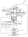
- FIG. 1 is an example of a side view showing the overall configuration of the spray inspection apparatus according to the first embodiment.
- FIG. 2 is an example of a plan view of a main body portion of the spray inspection apparatus according to the first embodiment.
- spray inspection apparatus 100 includes a normal temperature spray chamber 10, a freezing chamber 30 cooled to an extremely low temperature of ⁇ 100 ° C. or less, and a control unit 80.
- the spraying chamber 10 and the freezing chamber 30 have a cylindrical shape and communicate with each other.
- a shutter 60 that switches between communication and non-communication between the spray chamber 10 and the freezer compartment 30 is provided.
- the freezer compartment 30 and the shutter 60 are comprised by low heat transfer members, such as ceramics, for example.
- the shutter 60 has a disk shape and is provided with two windows 62 that are symmetrical with respect to the center point.
- the control unit 80 functions as a shutter control unit 82 that controls the rotation of the shutter 60.
- the shutter 60 When one of the two windows 62 is located between the spray chamber 10 and the freezer compartment 30 (the state shown in FIGS. 1 and 2), the shutter 60 becomes OPEN, and the spray chamber 10 and the freezer compartment 30 Communicate.
- the shutter 60 rotates 90 ° from this state, the shutter 60 is inserted between the spray chamber 10 and the freezing chamber 30, the shutter 60 becomes CLOSE, and the spray chamber 10 and the freezing chamber 30 are not in communication.
- the shutter 60 further rotates 90 °, the other of the two windows 62 is inserted between the spraying chamber 10 and the freezing chamber 30, and the shutter 60 becomes OPEN, and the spraying chamber 10 and the freezing chamber 30 communicate with each other. .
- An injection valve 12 is attached to the central part of the upper part of the spray chamber 10.
- the injection valve 12 injects fuel, for example, as a spray in accordance with an instruction from the control unit 80.
- the size of the spray particles injected from the injection valve 12 is, for example, 1 ⁇ m to 10 ⁇ m in diameter.
- the spray injected from the injection valve 12 is divided and diffused in the spray chamber 10.
- the side wall of the spray chamber 10 is made of glass, for example, and is transparent.
- a light source 72 is provided outside one side wall of the spray chamber 10.
- a high-speed camera 74 having, for example, 10,000 to 500,000 frame speed is provided outside the other side wall of the spray chamber 10 so as to face the light source 72.
- the high-speed camera 74 captures a spray image during spraying of spray sprayed from the injection valve 12.
- the lens 76 is used for focusing with a spray that is an object to be photographed by the high-speed camera 74.
- a first camera 14a and a second camera 14b are further mounted on both sides of the injection valve 12.
- the first camera 14a and the second camera 14b have different focal lengths.
- the focal length of the first camera 14a is longer than the focal length of the second camera 14b. The shooting by the first camera 14a and the second camera 14b will be described later.
- a cooling gas introduction pipe 32 is connected to the freezer compartment 30, and liquid nitrogen, for example, is introduced into the freezing compartment 30 as a cooling gas from the cooling gas introduction pipe 32. Thereby, the freezer compartment 30 is maintained at an extremely low temperature of ⁇ 100 ° C. or lower, for example.
- the cooling gas introduction pipe 32 is connected to the side wall 31 of the cylindrical freezing chamber 30 from an oblique direction.
- the cooling gas introduction pipe 32 is provided with a pressure gauge 34 and a flow rate adjustment valve 36. Opening and closing of the flow rate adjusting valve 36 is controlled by the control unit 80.
- a temperature center 38 is mounted on the side wall 31 of the freezer compartment 30, and the controller 80 controls the flow rate adjustment valve 36 according to the temperature in the freezer compartment 30 measured by the temperature sensor 38, and Adjust the amount of liquid nitrogen that flows in.
- control unit 80 functions as a cooling gas control unit 84 that controls the flow rate of the cooling gas flowing into the freezer compartment 30. For example, the control unit 80 adjusts the amount of cooling gas flowing into the freezer compartment 30 so that the temperature in the freezer compartment 30 is maintained at a predetermined temperature.
- a transparent saucer 40 is provided in the freezer compartment 30, a transparent saucer 40 is provided.
- the spray particles injected from the injection valve 12 are frozen when they reach the freezer compartment 30 to become frozen spray particles 42.
- the tray 40 holds the freeze spray particles 42.
- a light source 44 is attached to the lower part of the freezer compartment 30, and the light source 44 emits light under the control of the power source 68 by the control unit 80.
- the first camera 14 a and the second camera 14 b take images of the frozen spray particles 42 illuminated by the light source 44 according to instructions from the control unit 80.
- the control unit 80 analyzes the frozen spray particles 42 from the images of the frozen spray particles 42 photographed by the first camera 14a and the second camera 14b. For example, the average particle size, particle size distribution, and mass distribution of the freeze spray particles 42 are obtained.
- control unit 80 functions as an analysis unit 86 that analyzes the frozen spray particles 42.
- the freeze spray particles 42 held by the tray 40 include those having a large particle size and small particles.
- the frozen spray particles 42 having a small particle diameter are photographed more clearly by the first camera 14a (focal point 1) having a long focal length, and the frozen spray particles 42 having a large particle diameter are captured by the second camera 14b (focal point 2) having a short focal distance. ) For a clearer picture.
- An inverter 70 for inverting the tray 40 is provided, and the inverter 70 is controlled by the control unit 80.
- the control unit 80 captures the frozen spray particles 42 held by the receiving tray 40 with the first camera 14a and the second camera 14b, and then reverses the receiving tray 40 by the inverter 70 to thereby freeze the spray spray held by the receiving tray 40. Particles 42 are dropped onto the bottom of the freezer compartment 30. That is, the control unit 80 includes a reversal control unit 88 that reverses the tray 40 after the photographing of the frozen spray particles 42 is completed.
- a recess 46 is provided at the bottom of the freezer compartment 30.
- a discharge pipe 48 is connected to the bottom surface of the recess 46, and the frozen spray particles 42 dropped from the receiving tray 40 are guided to the discharge pipe 48.
- the discharge pipe 48 is provided with a valve 50 that is an electromagnetic valve controlled by the control unit 80. When the valve 50 becomes OPEN, the frozen spray particles 42 are collected in a collection container 52 connected to the discharge pipe 48. Is done.
- FIG. 3 is an example of a flowchart showing a method for analyzing the frozen spray particles 42.
- control unit 80 drives motor 64 to rotate shutter 60 by 90 °, and sets shutter 60 to OPEN (step S10).
- the spray chamber 10 and the freezing chamber 30 communicate with each other, and the spray particles injected from the injection valve 12 reach the freezer chamber 30 and are frozen in the freezer chamber 30 to become frozen spray particles 42.
- the freeze spray particles 42 are held by a tray 40 provided in the freezer compartment 30.
- control unit 80 drives the motor 64 to further rotate the shutter 60 by 90 ° after the first predetermined time has elapsed after the injection of the injection valve 12 is completed, and sets the shutter 60 to CLOSE (step S12).
- the first predetermined time can be determined in consideration of the splitting time of the spray injected from the injection valve 12.
- control unit 80 drives the motor 64 to rotate the shutter 60 by 90 ° after the second predetermined time has elapsed after the shutter 60 is closed, and sets the shutter 60 to OPEN (step S14).
- the second predetermined time can be determined in consideration of the freezing time of the spray particles and the time during which the frozen spray particles 42 are stably deposited on the tray 40.
- control unit 80 causes the light source 44 to emit light in a state where the shutter 60 is opened, and images the frozen spray particles 42 held in the tray 40 using the first camera 14a and the second camera 14b (step S40). S16). After the photographing is finished, the control unit 80 drives the motor 64 to rotate the shutter 60 by 90 °, and sets the shutter 60 to CLOSE (step S18). Next, the control unit 80 analyzes the frozen spray particles 42 from the captured images of the frozen spray particles 42 captured by the first camera 14a and the second camera 14b (step S20). For example, the average particle size, particle size distribution, mass distribution, etc. of the freeze spray particles 42 are obtained.
- the freezing chamber 30 for freezing the spray particles injected from the injection valve 12 and the tray 40 (freeze spray holding means) for holding the frozen spray particles 42 are used.
- analyzing means 86 for analyzing the frozen spray particles 42 by photographing the frozen spray particles 42 held by the tray 40 with the first camera 14a and the second camera 14b.
- the analysis unit 86 analyzes the frozen spray particles 42 from the photographed image, and obtains, for example, the average particle size, particle size distribution, and mass distribution of the frozen spray particles 42.
- the spray particles injected from the injection valve 12 are frozen and solidified into the frozen spray particles 42, whereby the shape of the spray can be maintained for a long time. Therefore, it is possible to accurately analyze the spray by capturing the frozen spray particles 42 and analyzing the frozen spray particles 42 from the captured image.
- the case where the frozen spray particles 42 are analyzed by photographing the frozen spray particles 42 with the first camera 14a and the second camera 14b having different focal lengths is shown as an example.
- the particle size of the freeze-sprayed particles 42 held by the receiving tray 40 varies, from ultrafine particles to coarse particles. Therefore, by photographing such frozen spray particles 42 with the first camera 14a and the second camera 14b having different focal lengths, it is possible to photograph all the particles from ultrafine particles to coarse particles. That is, it becomes possible to analyze the frozen spray particles 42 having different particle sizes.
- one camera that cannot change the focal length may be mounted and the frozen spray particles 42 held on the tray 40 may be photographed by this camera.
- the light source 44 is attached to the bottom of the freezing chamber 30 and the frozen spray particles 42 are photographed by illuminating the frozen spray particles 42 from the lower side of the receiving tray 40.
- the light source 44 may be mounted on the pan 40 to illuminate the frozen spray particles 42 from above. In this case, the tray 40 may not be transparent.
- a freezing chamber 30 provided with a receiving tray 40, and a shutter 60 for switching communication and non-communication between the spray chamber 10 and the freezing chamber 30.
- Control of the shutter 60 as shown in FIG. 3 is preferable from the viewpoint of maintaining the low temperature of the freezing chamber 30 and suppressing the temperature reduction of the spray chamber 10. That is, the shutter 60 is opened immediately before or after the start of spraying of the spray from the injection valve 12, the shutter 60 is closed after a lapse of the first predetermined time from the end of the injection, and then the shutter 60 is opened again after the lapse of the second predetermined time. It is preferable to close the shutter 60 after the photographing is finished. It is preferable that the first predetermined time and the second predetermined time can be arbitrarily changed by the user.
- a temperature sensor 38 for measuring the temperature in the freezer compartment 30 and to control the amount of cooling gas introduced into the freezer compartment 30 so that the temperature measured by the temperature sensor 38 becomes a predetermined temperature. Thereby, since the temperature in the freezer compartment 30 can be maintained at a predetermined temperature, the spray particles injected from the injection valve 12 can be more reliably frozen.
- the freezer compartment 30 has a cylindrical shape, and a cooling gas introduction pipe 32 for flowing a cooling gas introduced into the freezer compartment 30 is connected to the side wall 31 of the cylindrical freezer compartment 30 from an oblique direction.
- a cooling gas introduction pipe 32 for flowing a cooling gas introduced into the freezer compartment 30 is connected to the side wall 31 of the cylindrical freezer compartment 30 from an oblique direction.
- the cooling gas introduction pipe 32 is more preferably connected to the side wall 31 of the freezer compartment 30 from the tangential direction. This is because the cooling gas can be efficiently swirled in the freezer compartment 30.
- the freezer compartment 30 and the shutter 60 are preferably made up of members having a lower heat transfer coefficient than the members that make up the spray chamber 10. Thereby, it can suppress that the temperature in the freezer compartment 30 rises with external temperature or the temperature in the spray chamber 10.
- the frozen spray particles 42 After the analysis of the frozen spray particles 42 is completed, it is preferable to collect the frozen spray particles 42 from the tray 40 by inverting the tray 40 by the inverter 70 and dropping the frozen spray particles 42 from the tray 40. Thereby, since the freeze spray particles 42 can be quickly collected, the freeze spray particles 42 can be collected before vaporizing, and the fuel remaining in the freezer compartment 30 can be reduced.
- the method of collecting the frozen spray particles 42 from the receiving tray 40 is not limited to the case where the receiving tray 40 is inverted and dropped from the receiving tray 40. By tilting the receiving tray 40, the frozen spray particles 42 may be recovered by dropping the frozen spray particles 42 from the receiving tray 40. Further, the frozen spray particles 42 may be collected from the tray 40 after the analysis of the frozen spray particles 42 is finished by other methods.
- the freeze spray particles 42 When collecting the freeze spray particles 42, it is preferable to collect the freeze spray particles 42 in the collection container 52 through the discharge pipe 48. As a result, the fuel can be reused. Furthermore, by providing the valve 50 in the discharge pipe 48, the temperature rise of the freezer compartment 30 can be suppressed, and by using the valve 50 as an electromagnetic valve, the operator can be prevented from frostbite when the valve 50 is opened and closed.
- FIG. 4 is an example of a side view of the saucer 40.
- the surface of the saucer 40 is provided with fine protrusions 54 having an interval of 0.1 ⁇ m or less.
- maintained is preferable.
- the contact area between the frozen spray particles 42 and the tray 40 is reduced, and the heat insulating layer of air can prevent the frozen spray particles 42 having a small heat capacity, for example, about 1 ⁇ m from icing on the tray 40.
- the fine protrusions 54 may be formed by chemical processing using machining or chemicals, or animal or plant hair may be used.
- a light source 72 is arranged outside one side wall of the spray chamber 10, and a high-speed camera 74 is arranged outside the other side wall opposite to the one side wall, and the fuel is injected from the injection valve 12. It is preferable that a high-speed camera 74 captures a spray image during spraying. Thereby, since the spray image during spraying can also be imaged, the spray shape can be made clearer.
- FIG. 5 is an example of a side view showing an overall configuration of a spray inspection apparatus according to a modification of the first embodiment.
- the spray inspection apparatus 200 is provided with a stirring fan 56 that stirs the air in the freezer compartment 30 at the bottom of the freezer compartment 30.
- the stirring fan 56 is driven by a driving device 71 controlled by the control unit 80.
- the other configuration is the same as that of the first embodiment and is shown in FIGS. 1 and 2, and thus the description thereof is omitted here.
- the stirring fan 56 is provided in the freezer compartment 30.
- the temperature in the freezer compartment 30 can be made uniform by driving the stirring fan 56 with the shutter 60 in the CLOSE state. Therefore, the spray particles injected from the injection valve 12 can be frozen evenly.
- the stirring fan 56 is provided in the freezer compartment 30.
- FIG. 6 is an example of a side view illustrating the overall configuration of the spray inspection apparatus according to the second embodiment.
- surface roughness measuring instrument 16 is mounted on the upper part of spray chamber 10 instead of first camera 14 a and second camera 14 b.
- the light source 44 is not attached to the bottom of the freezer compartment 30.
- the other configuration is the same as that of the first embodiment and is shown in FIGS. 1 and 2, and thus the description thereof is omitted here.
- the surface roughness measuring device 16 is, for example, a light wave interference type surface roughness measuring device, and scans the entire surface of the tray 40 holding the frozen spray particles 42 in accordance with an instruction from the control unit 80 to thereby scan the entire surface of the tray 40. Measure the roughness. Then, the control unit 80 analyzes the frozen spray particles 42 from the surface roughness of the tray 40 measured by the surface roughness measuring device 16. For example, the particle size, the number of particles, and the like of the freeze spray particles 42 are calculated.
- the frozen spray particles 42 held on the tray 40 may be analyzed by measuring the roughness of the entire surface of the tray 40 on which the frozen spray particles 42 are held.
- the surface of the tray 40 becomes a measurement standard by the surface roughness measuring device 16, and the freeze spray particles 42 can be analyzed with high accuracy and in a short time.
- FIG. 7 is an example of a side view showing the overall configuration of the spray inspection apparatus according to the third embodiment.
- FIG. 8 is an example of a plan view of the main body of the spray inspection apparatus according to the third embodiment.
- the spray inspection apparatus 400 includes a spray chamber 10, a freezer chamber 30, a control unit 80, and a shutter 60.
- a hot air inflow pipe 20 for sending hot air is connected to the upper part of the spray chamber 10, and a valve 22 is provided in the hot air inflow pipe 20.
- the first camera 14a and the second camera 14b as in the first embodiment are not attached.
- each tray 40 In the freezer compartment 30, for example, eight trays 40 are sequentially provided so as to overlap each other at intervals.
- the tray 40 located at the lowermost stage has a flat bottom shape.
- the trays 40 other than the lowermost stage are mesh-shaped, and the mesh coarseness increases toward the upper stage. The mesh roughness of each tray 40 is examined in advance.
- the spray particles injected from the injection valve 12 are frozen in the freezer compartment 30 and become frozen spray particles 42 mixed with various particle sizes.
- the tray 40 has a function of holding the frozen spray particles 42. However, since the mesh is coarser in the upper stage, the frozen spray particles 42 having a larger particle size are held by the tray 40 on the upper stage side and are frozen with a smaller particle diameter.
- the spray particles 42 are held by a lower tray 40. Since the lowermost tray 40 has a flat bottom without a mesh, the ultrafine frozen spray particles 42 that pass through all the mesh-shaped tray 40 are held by the lowermost tray 40. That is, each of the trays 40 holds the freeze spray particles 42 for each particle size.
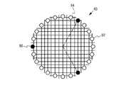
- FIG. 9 is an example of a plan view of the tray 40.
- the mesh-shaped receiving tray 40 is illustrated as an example.
- the tray 40 has a disk shape, and is provided with a recess 90 at every 120 ° on the outer peripheral portion.
- a through hole 92 is further provided in the outer peripheral portion of the tray 40 at a portion excluding the recess 90 every 15 °.
- each tray 40 is stably supported by support columns 94 by three concave portions 90 provided every 120 °.
- a through-hole 92 provided every 15 ° is penetrated by a support column 94 that supports the other tray 40, and the support column 94 and the through-hole 92 do not interfere with each other.
- a load sensor 96 is provided at the bottom of the freezer compartment 30. Three struts 94 that support each tray 40 are bonded to one and then bonded to a load sensor 96.
- a mass meter 98 is connected to each load sensor 96, whereby the mass of each tray 40 can be measured.
- the control unit 80 analyzes the frozen spray particles 42 by measuring the mass of each tray 40 with the mass meter 98 and obtaining the mass of the frozen spray particles 42 for each particle size held by each tray 40. For example, the number of particles is calculated from the mass of each particle size, and the particle size distribution and mass distribution are obtained.
- a spray guide 95 which is located above the through hole 92 provided in the tray 40 and is curved inward from the side wall of the freezer compartment 30 is provided. With the spray guide 95, it is possible to suppress the spray injected from the injection valve 12 from being removed from the through hole 92.
- the spray guide 95 is preferably removable.
- One end of a discharge pipe 48 provided with a valve 50 is connected to the bottom of the freezer compartment 30, and a recovery container 52 is connected to the other end of the discharge pipe 48.
- FIG. 10 is an example of a flowchart showing a method for analyzing the frozen spray particles 42.
- control unit 80 drives motor 64 to rotate shutter 60 by 90 °, and sets shutter 60 to OPEN (step S30).
- the spray chamber 10 and the freezing chamber 30 communicate with each other, and the spray particles injected from the injection valve 12 are frozen in the freezing chamber 30 to become frozen spray particles 42.
- the freeze spray particles 42 are held in each tray 40 for each particle size.
- the control unit 80 drives the motor 64 to further rotate the shutter 60 by 90 ° after the first predetermined time has elapsed from the end of injection, and sets the shutter 60 to CLOSE (step S32).
- the first predetermined time can be determined in consideration of the splitting time of the spray injected from the injection valve 12.
- control unit 80 measures the mass of each tray 40 after a lapse of a certain time after the shutter 60 is closed (step S34). And the control part 80 calculates
- the freeze spray particles 42 are collected by the following method. First, after the analysis of the frozen spray particles 42 is completed, the shutter 60 is rotated by 90 °, the shutter 60 is set to OPEN, and the spray chamber 10 and the freezing chamber 30 are communicated. Then, with the valve 22 of the hot air inflow pipe 20 connected to the upper part of the spray chamber 10 as OPEN, hot air is sent from the spray chamber 10 toward the freezing chamber 30, and the frozen spray particles 42 held in each tray 40 are thawed. Let The thawed frozen spray particles 42 are collected in the collection container 52 through the discharge pipe 48 with the valve 50 set to OPEN. And after collection
- the frozen spray particles 42 are analyzed by measuring the mass of the frozen spray particles 42 held in each of the plurality of trays 40 as in the third embodiment, provided with the plurality of trays 40 having meshes of different roughness. But you can. Since each freeze tray 40 holds the frozen spray particles 42 classified for each particle size, the mass of the frozen spray particles 42 for each particle size is obtained. The number of particles can be calculated from the mass of the frozen spray particles 42 for each particle size, and the particle size distribution and mass distribution are obtained.
- the frozen spray particles 42 After completion of the analysis of the frozen spray particles 42, it is preferable to recover the frozen spray particles 42 by thawing the frozen spray particles 42 held in the tray 40. Thereby, even when there are a plurality of trays 40 for holding the frozen spray particles 42, the frozen spray particles 42 can be quickly and easily collected.
- the case where the number of the trays 40 is eight has been described as an example.
- the embodiment is not limited thereto, and a plurality of trays 40 having meshes with different roughnesses may be provided.
- the bottom tray 40 is preferably a flat bottom, but may be a mesh having a very fine mesh.
- the spray sprayed from the injection valve 12 has been described as including many spray particles.
- several spray particles such as one or two spray particles are sprayed from the spray valve 12. It may be the case.
Landscapes
- Chemical & Material Sciences (AREA)
- Physics & Mathematics (AREA)
- Health & Medical Sciences (AREA)
- Life Sciences & Earth Sciences (AREA)
- Analytical Chemistry (AREA)
- Biochemistry (AREA)
- General Health & Medical Sciences (AREA)
- General Physics & Mathematics (AREA)
- Immunology (AREA)
- Pathology (AREA)
- Dispersion Chemistry (AREA)
- Sampling And Sample Adjustment (AREA)
Abstract
Description
12 噴射弁
14a 第1カメラ
14b 第2カメラ
16 表面粗さ測定器
20 温風流入管
30 冷凍室
31 冷凍室の側壁
32 冷却ガス導入管
34 圧力計
36 流量調整弁
38 温度センサ
40 受け皿
42 凍結噴霧粒子
44 光源
46 凹部
48 排出管
52 回収容器
54 微細突起
56 攪拌用ファン
60 シャッター
62 窓
64 モータ
66 歯車
68 電源
70 反転器
71 駆動装置
72 光源
74 高速度カメラ
76 レンズ
80 制御部
82 シャッター制御手段
84 冷却ガス制御手段
86 解析手段
88 反転制御手段
90 凹部
92 貫通孔
94 支柱
95 噴霧ガイド
96 荷重センサ
98 質量計
100 噴霧検査装置
200 噴霧検査装置
300 噴霧検査装置
400 噴霧検査装置
Claims (17)
- 噴射弁から噴射された噴霧粒子を凍結させる噴霧凍結手段と、
前記噴霧凍結手段で凍結された凍結噴霧粒子を保持する凍結噴霧保持手段と、
前記凍結噴霧保持手段で保持された凍結噴霧粒子を解析する解析手段と、を備えることを特徴とする噴霧検査装置。 - 前記解析手段は、前記凍結噴霧保持手段で保持された凍結噴霧粒子を撮影することによって、前記凍結噴霧粒子を解析することを特徴とする請求項1記載の噴霧検査装置。
- 前記凍結噴霧保持手段で保持された凍結噴霧粒子を2以上の異なる焦点距離で撮影することを特徴とする請求項2記載の噴霧検査装置。
- 前記解析手段は、前記凍結噴霧粒子を保持する前記凍結噴霧保持手段の表面粗さを測定することによって、前記凍結噴霧粒子を解析することを特徴とする請求項1記載の噴霧検査装置。
- 異なる粗さのメッシュを有する複数の前記凍結噴霧保持手段を備え、
前記解析手段は、前記複数の凍結噴霧保持手段それぞれに保持された凍結噴霧粒子の質量を測定することによって、前記凍結噴霧粒子を解析することを特徴とする請求項1記載の噴霧検査装置。 - 前記噴射弁から噴射された噴霧の分裂および拡散を行う噴霧室と、
前記噴霧室と連通し、前記分裂および拡散した後の噴霧粒子を凍結させる低温に維持され、前記凍結噴霧保持手段が設けられた冷凍室と、
前記噴霧室と前記冷凍室との連通および非連通を切り換えるシャッターと、を備えることを特徴とする請求項1から5のいずれか一項記載の噴霧検査装置。 - 前記噴射弁からの噴霧の噴射が終了してから前記シャッターを閉じるシャッター制御手段を備えることを特徴とする請求項6記載の噴霧検査装置。
- 前記冷凍室内の温度を測定する温度測定手段と、
前記温度測定手段で測定された温度が所定の温度となるように前記冷凍室に導入する冷却ガスの量を制御する冷却ガス制御手段と、を備えることを特徴とする請求項6または7記載の噴霧検査装置。 - 前記冷凍室は円筒形状をしており、
円筒形状をした前記冷凍室の側壁に対して斜め方向から、前記冷凍室に導入する冷却ガスを流す冷却ガス導入管が、前記冷凍室に接続されていることを特徴とする請求項6から8のいずれか一項記載の噴霧検査装置。 - 前記冷凍室および前記シャッターは、前記噴霧室を構成する部材よりも熱伝達率の低い部材で構成されることを特徴とする請求項6から9のいずれか一項記載の噴霧検査装置。
- 前記冷凍室内に攪拌手段が設けられていることを特徴とする請求項6から10のいずれか一項記載の噴霧検査装置。
- 前記解析手段による解析終了後、前記凍結噴霧保持手段から前記凍結噴霧粒子を回収する凍結噴霧回収手段を備えることを特徴とする請求項1から11のいずれか一項記載の噴霧検査装置。
- 前記凍結噴霧回収手段は、前記凍結噴霧保持手段を傾斜させて、前記凍結噴霧保持手段で保持された凍結噴霧粒子を前記凍結噴霧保持手段から落とすことによって、前記凍結噴霧粒子を回収することを特徴とする請求項12記載の噴霧検査装置。
- 前記凍結噴霧回収手段は、前記凍結噴霧保持手段で保持された凍結噴霧粒子を解凍させることによって、前記凍結噴霧粒子を回収することを特徴とする請求項12記載の噴霧検査装置。
- 前記凍結噴霧粒子は、排出通路を介して回収容器に回収されることを特徴とする請求項12から14のいずれか一項記載の噴霧検査装置。
- 前記凍結噴霧保持手段には0.1μm以下の間隔の微細突起が設けられていて、前記微細突起上で前記噴霧凍結粒子を保持することを特徴とする請求項1から15のいずれか一項記載の噴霧検査装置。
- 前記噴射弁から噴射された噴霧の噴霧中の噴霧画像を撮影する撮影手段を備えることを特徴とする請求項1から16のいずれか一項記載の噴霧検査装置。
Priority Applications (5)
| Application Number | Priority Date | Filing Date | Title |
|---|---|---|---|
| US14/003,979 US9116085B2 (en) | 2011-03-30 | 2011-03-30 | Mist testing device |
| PCT/JP2011/058011 WO2012131935A1 (ja) | 2011-03-30 | 2011-03-30 | 噴霧検査装置 |
| EP11862262.0A EP2693190A4 (en) | 2011-03-30 | 2011-03-30 | FOG INSPECTION DEVICE |
| CN201180069874.7A CN103460016B (zh) | 2011-03-30 | 2011-03-30 | 喷雾检查装置 |
| JP2013506942A JP5692361B2 (ja) | 2011-03-30 | 2011-03-30 | 噴霧検査装置 |
Applications Claiming Priority (1)
| Application Number | Priority Date | Filing Date | Title |
|---|---|---|---|
| PCT/JP2011/058011 WO2012131935A1 (ja) | 2011-03-30 | 2011-03-30 | 噴霧検査装置 |
Publications (1)
| Publication Number | Publication Date |
|---|---|
| WO2012131935A1 true WO2012131935A1 (ja) | 2012-10-04 |
Family
ID=46929761
Family Applications (1)
| Application Number | Title | Priority Date | Filing Date |
|---|---|---|---|
| PCT/JP2011/058011 WO2012131935A1 (ja) | 2011-03-30 | 2011-03-30 | 噴霧検査装置 |
Country Status (5)
| Country | Link |
|---|---|
| US (1) | US9116085B2 (ja) |
| EP (1) | EP2693190A4 (ja) |
| JP (1) | JP5692361B2 (ja) |
| CN (1) | CN103460016B (ja) |
| WO (1) | WO2012131935A1 (ja) |
Cited By (1)
| Publication number | Priority date | Publication date | Assignee | Title |
|---|---|---|---|---|
| US9429125B2 (en) | 2011-04-26 | 2016-08-30 | Toyota Jidosha Kabushiki Kaisha | Spray measuring method and spray test apparatus used in the method |
Families Citing this family (5)
| Publication number | Priority date | Publication date | Assignee | Title |
|---|---|---|---|---|
| CN104181083B (zh) * | 2014-08-27 | 2016-10-19 | 天津商业大学 | 一种喷雾特性参数检测装置及方法 |
| CN105372165B (zh) * | 2015-12-22 | 2018-07-17 | 东南大学 | 一种基于疏水材料的液滴直径分布测量方法 |
| CN105738243B (zh) * | 2016-04-13 | 2019-01-08 | 中国科学院工程热物理研究所 | 粉末射流特性的检测方法及装置 |
| DE102017006969A1 (de) | 2017-07-22 | 2019-01-24 | Fimro Gmbh | Anordnung und Verfahren zur Prüfung der Funktion eines Sprühwerkzeugs |
| US20210217670A1 (en) * | 2020-01-15 | 2021-07-15 | Taiwan Semiconductor Manufacturing Co., Ltd. | Method of manufacturing semiconductor devices |
Citations (4)
| Publication number | Priority date | Publication date | Assignee | Title |
|---|---|---|---|---|
| JPS62279835A (ja) * | 1986-05-27 | 1987-12-04 | Oogawara Kakoki Kk | 連続造粒装置の粒径制御装置 |
| JPH0136055B2 (ja) | 1980-08-28 | 1989-07-28 | Nitta Gelatin Kk | |
| JPH11352021A (ja) * | 1998-06-05 | 1999-12-24 | Unisia Jecs Corp | 噴射弁の噴霧パターン検査装置 |
| WO2010005021A1 (ja) * | 2008-07-10 | 2010-01-14 | 株式会社アルバック | 凍結乾燥装置及び凍結乾燥方法 |
Family Cites Families (16)
| Publication number | Priority date | Publication date | Assignee | Title |
|---|---|---|---|---|
| US3011336A (en) * | 1957-04-30 | 1961-12-05 | Malcolm A Weiss | Droplet sampling probe |
| US4123159A (en) * | 1977-02-09 | 1978-10-31 | Werner Hollander | Apparatus for analyzing the size distribution and quantity of small particles in an aerosol |
| JPS54107358A (en) * | 1978-02-10 | 1979-08-23 | Diesel Kiki Co | Particle size measuring apparatus |
| JPS54153696A (en) * | 1978-05-24 | 1979-12-04 | Hitachi Ltd | Fine particle detecting system of revolving electric apparatus |
| NZ208274A (en) * | 1984-05-24 | 1986-10-08 | M P Best | Calculating aerosol particle size:crystallising droplets on a surface |
| JPH0648238B2 (ja) | 1986-05-21 | 1994-06-22 | 武征 神本 | 噴射燃料の平均粒径計測装置 |
| US5316579A (en) * | 1988-12-27 | 1994-05-31 | Symetrix Corporation | Apparatus for forming a thin film with a mist forming means |
| US6734965B2 (en) * | 2000-09-18 | 2004-05-11 | Douglas G. Talley | Optical patternation method |
| CN1252451C (zh) * | 2002-06-05 | 2006-04-19 | 中国科学技术大学 | 基于激光片光成像的粒子场全场测量方法及其装置 |
| US6786194B2 (en) * | 2002-10-31 | 2004-09-07 | Hewlett-Packard Development Company, L.P. | Variable fuel delivery system and method |
| JP3975968B2 (ja) * | 2003-05-13 | 2007-09-12 | 株式会社Ihi | 噴霧計測方法及び装置 |
| DE102005049227B4 (de) * | 2005-10-14 | 2007-10-11 | Fraunhofer-Gesellschaft zur Förderung der angewandten Forschung e.V. | Vorrichtung und Verfahren zur Überwachung der Partikelfracht eines Fluids |
| DE102007060701A1 (de) | 2007-12-17 | 2008-06-26 | Daimler Ag | Vorrichtung und Verfahren zum Auffangen und Abscheiden von Partikeln hergestellt mittels eines thermischen Spritzverfahrens |
| AT10542U3 (de) * | 2009-01-19 | 2009-10-15 | Avl List Gmbh | Kondensationskern-zähler |
| EP2482721B1 (de) | 2009-09-30 | 2013-08-28 | MTI Medtech Innovation GmbH | Vorrichtung und verfahren zur fraktionierten gewinnung von inhaltsstoffen der ausatemluft |
| DE202009013577U1 (de) | 2009-09-30 | 2010-02-11 | Filt Lungen- Und Thoraxdiagnostik Gmbh | Vorrichtung zur fraktionierten Gewinnung von Inhaltsstoffen der Ausatemluft |
-
2011
- 2011-03-30 EP EP11862262.0A patent/EP2693190A4/en not_active Withdrawn
- 2011-03-30 JP JP2013506942A patent/JP5692361B2/ja not_active Expired - Fee Related
- 2011-03-30 US US14/003,979 patent/US9116085B2/en not_active Expired - Fee Related
- 2011-03-30 WO PCT/JP2011/058011 patent/WO2012131935A1/ja active Application Filing
- 2011-03-30 CN CN201180069874.7A patent/CN103460016B/zh not_active Expired - Fee Related
Patent Citations (4)
| Publication number | Priority date | Publication date | Assignee | Title |
|---|---|---|---|---|
| JPH0136055B2 (ja) | 1980-08-28 | 1989-07-28 | Nitta Gelatin Kk | |
| JPS62279835A (ja) * | 1986-05-27 | 1987-12-04 | Oogawara Kakoki Kk | 連続造粒装置の粒径制御装置 |
| JPH11352021A (ja) * | 1998-06-05 | 1999-12-24 | Unisia Jecs Corp | 噴射弁の噴霧パターン検査装置 |
| WO2010005021A1 (ja) * | 2008-07-10 | 2010-01-14 | 株式会社アルバック | 凍結乾燥装置及び凍結乾燥方法 |
Non-Patent Citations (1)
| Title |
|---|
| See also references of EP2693190A4 |
Cited By (1)
| Publication number | Priority date | Publication date | Assignee | Title |
|---|---|---|---|---|
| US9429125B2 (en) | 2011-04-26 | 2016-08-30 | Toyota Jidosha Kabushiki Kaisha | Spray measuring method and spray test apparatus used in the method |
Also Published As
| Publication number | Publication date |
|---|---|
| US20140007661A1 (en) | 2014-01-09 |
| CN103460016B (zh) | 2015-09-16 |
| US9116085B2 (en) | 2015-08-25 |
| EP2693190A1 (en) | 2014-02-05 |
| JPWO2012131935A1 (ja) | 2014-07-24 |
| CN103460016A (zh) | 2013-12-18 |
| EP2693190A4 (en) | 2015-01-14 |
| JP5692361B2 (ja) | 2015-04-01 |
Similar Documents
| Publication | Publication Date | Title |
|---|---|---|
| JP5692361B2 (ja) | 噴霧検査装置 | |
| Versluis | High-speed imaging in fluids | |
| US7338168B2 (en) | Particle analyzing system and methodology | |
| CN1967224B (zh) | 用于表面分析的光谱仪及表面分析方法 | |
| US7692131B2 (en) | Imaging system and methodology with projected pixels mapped to the diffraction limited spot | |
| TW201643240A (zh) | 用於微流體裝置之培養站 | |
| US7248716B2 (en) | Imaging system, methodology, and applications employing reciprocal space optical design | |
| WO2018143102A1 (ja) | 細胞培養装置、撮像ユニット及び培養監視方法 | |
| US9965867B2 (en) | Particle control device | |
| JP6513802B2 (ja) | ナノ粒子検出のためのレーザー光結合 | |
| JP2009258746A (ja) | 撮像システムおよび逆空間光学設計を用いる方法 | |
| JP2002310848A5 (ja) | ||
| US10324022B2 (en) | Analysis accuracy improvement in automated testing apparatus | |
| US20180361377A1 (en) | Sample manufacturing method, sample manufacturing kit, observation method, and observation device | |
| CN106501134A (zh) | 小角度接触角的精确测量方法 | |
| CN107533217A (zh) | 用于显微技术的方法与装置 | |
| RU2009116927A (ru) | Устройство и способ для наблюдения поверхности образца | |
| CN205263394U (zh) | 一种可自动移动的全息光镊装置 | |
| WO2024037035A1 (zh) | 基于角膜反射的投影装置、角膜照影仪、角膜地形图仪及其检测方法 | |
| JPH06174628A (ja) | 流れる固体粒子状物質の粒子の大きさの分布を測定するための方法および装置 | |
| CN109239056A (zh) | 一种高温液体成分在线检测装置及方法 | |
| JP4474663B2 (ja) | ビデオ顕微鏡装置 | |
| JP5477321B2 (ja) | 噴霧検査装置 | |
| CN109238969A (zh) | 一种低温光致发光快速高效测试方法 | |
| KR101798501B1 (ko) | 세포 배양장치 |
Legal Events
| Date | Code | Title | Description |
|---|---|---|---|
| 121 | Ep: the epo has been informed by wipo that ep was designated in this application |
Ref document number: 11862262 Country of ref document: EP Kind code of ref document: A1 |
|
| ENP | Entry into the national phase |
Ref document number: 2013506942 Country of ref document: JP Kind code of ref document: A |
|
| WWE | Wipo information: entry into national phase |
Ref document number: 14003979 Country of ref document: US |
|
| WWE | Wipo information: entry into national phase |
Ref document number: 2011862262 Country of ref document: EP |
|
| NENP | Non-entry into the national phase |
Ref country code: DE |