WO2012131919A1 - Semiconductor device and method for manufacturing same - Google Patents
Semiconductor device and method for manufacturing same Download PDFInfo
- Publication number
- WO2012131919A1 WO2012131919A1 PCT/JP2011/057885 JP2011057885W WO2012131919A1 WO 2012131919 A1 WO2012131919 A1 WO 2012131919A1 JP 2011057885 W JP2011057885 W JP 2011057885W WO 2012131919 A1 WO2012131919 A1 WO 2012131919A1
- Authority
- WO
- WIPO (PCT)
- Prior art keywords
- resin
- chip mounting
- mounting portion
- semiconductor device
- peripheral portion
- Prior art date
Links
Images


Classifications
-
- H—ELECTRICITY
- H01—ELECTRIC ELEMENTS
- H01L—SEMICONDUCTOR DEVICES NOT COVERED BY CLASS H10
- H01L23/00—Details of semiconductor or other solid state devices
- H01L23/28—Encapsulations, e.g. encapsulating layers, coatings, e.g. for protection
- H01L23/31—Encapsulations, e.g. encapsulating layers, coatings, e.g. for protection characterised by the arrangement or shape
- H01L23/3107—Encapsulations, e.g. encapsulating layers, coatings, e.g. for protection characterised by the arrangement or shape the device being completely enclosed
-
- H—ELECTRICITY
- H01—ELECTRIC ELEMENTS
- H01L—SEMICONDUCTOR DEVICES NOT COVERED BY CLASS H10
- H01L21/00—Processes or apparatus adapted for the manufacture or treatment of semiconductor or solid state devices or of parts thereof
- H01L21/02—Manufacture or treatment of semiconductor devices or of parts thereof
- H01L21/04—Manufacture or treatment of semiconductor devices or of parts thereof the devices having at least one potential-jump barrier or surface barrier, e.g. PN junction, depletion layer or carrier concentration layer
- H01L21/50—Assembly of semiconductor devices using processes or apparatus not provided for in a single one of the subgroups H01L21/06 - H01L21/326, e.g. sealing of a cap to a base of a container
- H01L21/56—Encapsulations, e.g. encapsulation layers, coatings
- H01L21/565—Moulds
-
- H—ELECTRICITY
- H01—ELECTRIC ELEMENTS
- H01L—SEMICONDUCTOR DEVICES NOT COVERED BY CLASS H10
- H01L23/00—Details of semiconductor or other solid state devices
- H01L23/48—Arrangements for conducting electric current to or from the solid state body in operation, e.g. leads, terminal arrangements ; Selection of materials therefor
- H01L23/488—Arrangements for conducting electric current to or from the solid state body in operation, e.g. leads, terminal arrangements ; Selection of materials therefor consisting of soldered or bonded constructions
- H01L23/495—Lead-frames or other flat leads
- H01L23/49541—Geometry of the lead-frame
- H01L23/49548—Cross section geometry
- H01L23/49551—Cross section geometry characterised by bent parts
-
- H—ELECTRICITY
- H01—ELECTRIC ELEMENTS
- H01L—SEMICONDUCTOR DEVICES NOT COVERED BY CLASS H10
- H01L23/00—Details of semiconductor or other solid state devices
- H01L23/48—Arrangements for conducting electric current to or from the solid state body in operation, e.g. leads, terminal arrangements ; Selection of materials therefor
- H01L23/488—Arrangements for conducting electric current to or from the solid state body in operation, e.g. leads, terminal arrangements ; Selection of materials therefor consisting of soldered or bonded constructions
- H01L23/495—Lead-frames or other flat leads
- H01L23/49575—Assemblies of semiconductor devices on lead frames
-
- H—ELECTRICITY
- H01—ELECTRIC ELEMENTS
- H01L—SEMICONDUCTOR DEVICES NOT COVERED BY CLASS H10
- H01L23/00—Details of semiconductor or other solid state devices
- H01L23/48—Arrangements for conducting electric current to or from the solid state body in operation, e.g. leads, terminal arrangements ; Selection of materials therefor
- H01L23/488—Arrangements for conducting electric current to or from the solid state body in operation, e.g. leads, terminal arrangements ; Selection of materials therefor consisting of soldered or bonded constructions
- H01L23/495—Lead-frames or other flat leads
- H01L23/49579—Lead-frames or other flat leads characterised by the materials of the lead frames or layers thereon
- H01L23/49582—Metallic layers on lead frames
-
- H—ELECTRICITY
- H01—ELECTRIC ELEMENTS
- H01L—SEMICONDUCTOR DEVICES NOT COVERED BY CLASS H10
- H01L2224/00—Indexing scheme for arrangements for connecting or disconnecting semiconductor or solid-state bodies and methods related thereto as covered by H01L24/00
- H01L2224/01—Means for bonding being attached to, or being formed on, the surface to be connected, e.g. chip-to-package, die-attach, "first-level" interconnects; Manufacturing methods related thereto
- H01L2224/26—Layer connectors, e.g. plate connectors, solder or adhesive layers; Manufacturing methods related thereto
- H01L2224/31—Structure, shape, material or disposition of the layer connectors after the connecting process
- H01L2224/32—Structure, shape, material or disposition of the layer connectors after the connecting process of an individual layer connector
- H01L2224/321—Disposition
- H01L2224/32151—Disposition the layer connector connecting between a semiconductor or solid-state body and an item not being a semiconductor or solid-state body, e.g. chip-to-substrate, chip-to-passive
- H01L2224/32221—Disposition the layer connector connecting between a semiconductor or solid-state body and an item not being a semiconductor or solid-state body, e.g. chip-to-substrate, chip-to-passive the body and the item being stacked
- H01L2224/32245—Disposition the layer connector connecting between a semiconductor or solid-state body and an item not being a semiconductor or solid-state body, e.g. chip-to-substrate, chip-to-passive the body and the item being stacked the item being metallic
-
- H—ELECTRICITY
- H01—ELECTRIC ELEMENTS
- H01L—SEMICONDUCTOR DEVICES NOT COVERED BY CLASS H10
- H01L2224/00—Indexing scheme for arrangements for connecting or disconnecting semiconductor or solid-state bodies and methods related thereto as covered by H01L24/00
- H01L2224/01—Means for bonding being attached to, or being formed on, the surface to be connected, e.g. chip-to-package, die-attach, "first-level" interconnects; Manufacturing methods related thereto
- H01L2224/42—Wire connectors; Manufacturing methods related thereto
- H01L2224/44—Structure, shape, material or disposition of the wire connectors prior to the connecting process
- H01L2224/45—Structure, shape, material or disposition of the wire connectors prior to the connecting process of an individual wire connector
- H01L2224/45001—Core members of the connector
- H01L2224/45099—Material
- H01L2224/451—Material with a principal constituent of the material being a metal or a metalloid, e.g. boron (B), silicon (Si), germanium (Ge), arsenic (As), antimony (Sb), tellurium (Te) and polonium (Po), and alloys thereof
- H01L2224/45138—Material with a principal constituent of the material being a metal or a metalloid, e.g. boron (B), silicon (Si), germanium (Ge), arsenic (As), antimony (Sb), tellurium (Te) and polonium (Po), and alloys thereof the principal constituent melting at a temperature of greater than or equal to 950°C and less than 1550°C
- H01L2224/45144—Gold (Au) as principal constituent
-
- H—ELECTRICITY
- H01—ELECTRIC ELEMENTS
- H01L—SEMICONDUCTOR DEVICES NOT COVERED BY CLASS H10
- H01L2224/00—Indexing scheme for arrangements for connecting or disconnecting semiconductor or solid-state bodies and methods related thereto as covered by H01L24/00
- H01L2224/01—Means for bonding being attached to, or being formed on, the surface to be connected, e.g. chip-to-package, die-attach, "first-level" interconnects; Manufacturing methods related thereto
- H01L2224/42—Wire connectors; Manufacturing methods related thereto
- H01L2224/44—Structure, shape, material or disposition of the wire connectors prior to the connecting process
- H01L2224/45—Structure, shape, material or disposition of the wire connectors prior to the connecting process of an individual wire connector
- H01L2224/45001—Core members of the connector
- H01L2224/45099—Material
- H01L2224/451—Material with a principal constituent of the material being a metal or a metalloid, e.g. boron (B), silicon (Si), germanium (Ge), arsenic (As), antimony (Sb), tellurium (Te) and polonium (Po), and alloys thereof
- H01L2224/45138—Material with a principal constituent of the material being a metal or a metalloid, e.g. boron (B), silicon (Si), germanium (Ge), arsenic (As), antimony (Sb), tellurium (Te) and polonium (Po), and alloys thereof the principal constituent melting at a temperature of greater than or equal to 950°C and less than 1550°C
- H01L2224/45147—Copper (Cu) as principal constituent
-
- H—ELECTRICITY
- H01—ELECTRIC ELEMENTS
- H01L—SEMICONDUCTOR DEVICES NOT COVERED BY CLASS H10
- H01L2224/00—Indexing scheme for arrangements for connecting or disconnecting semiconductor or solid-state bodies and methods related thereto as covered by H01L24/00
- H01L2224/01—Means for bonding being attached to, or being formed on, the surface to be connected, e.g. chip-to-package, die-attach, "first-level" interconnects; Manufacturing methods related thereto
- H01L2224/42—Wire connectors; Manufacturing methods related thereto
- H01L2224/44—Structure, shape, material or disposition of the wire connectors prior to the connecting process
- H01L2224/45—Structure, shape, material or disposition of the wire connectors prior to the connecting process of an individual wire connector
- H01L2224/45001—Core members of the connector
- H01L2224/45099—Material
- H01L2224/451—Material with a principal constituent of the material being a metal or a metalloid, e.g. boron (B), silicon (Si), germanium (Ge), arsenic (As), antimony (Sb), tellurium (Te) and polonium (Po), and alloys thereof
- H01L2224/45163—Material with a principal constituent of the material being a metal or a metalloid, e.g. boron (B), silicon (Si), germanium (Ge), arsenic (As), antimony (Sb), tellurium (Te) and polonium (Po), and alloys thereof the principal constituent melting at a temperature of greater than 1550°C
- H01L2224/45164—Palladium (Pd) as principal constituent
-
- H—ELECTRICITY
- H01—ELECTRIC ELEMENTS
- H01L—SEMICONDUCTOR DEVICES NOT COVERED BY CLASS H10
- H01L2224/00—Indexing scheme for arrangements for connecting or disconnecting semiconductor or solid-state bodies and methods related thereto as covered by H01L24/00
- H01L2224/01—Means for bonding being attached to, or being formed on, the surface to be connected, e.g. chip-to-package, die-attach, "first-level" interconnects; Manufacturing methods related thereto
- H01L2224/42—Wire connectors; Manufacturing methods related thereto
- H01L2224/47—Structure, shape, material or disposition of the wire connectors after the connecting process
- H01L2224/48—Structure, shape, material or disposition of the wire connectors after the connecting process of an individual wire connector
- H01L2224/4805—Shape
- H01L2224/4809—Loop shape
- H01L2224/48091—Arched
-
- H—ELECTRICITY
- H01—ELECTRIC ELEMENTS
- H01L—SEMICONDUCTOR DEVICES NOT COVERED BY CLASS H10
- H01L2224/00—Indexing scheme for arrangements for connecting or disconnecting semiconductor or solid-state bodies and methods related thereto as covered by H01L24/00
- H01L2224/01—Means for bonding being attached to, or being formed on, the surface to be connected, e.g. chip-to-package, die-attach, "first-level" interconnects; Manufacturing methods related thereto
- H01L2224/42—Wire connectors; Manufacturing methods related thereto
- H01L2224/47—Structure, shape, material or disposition of the wire connectors after the connecting process
- H01L2224/48—Structure, shape, material or disposition of the wire connectors after the connecting process of an individual wire connector
- H01L2224/481—Disposition
- H01L2224/48135—Connecting between different semiconductor or solid-state bodies, i.e. chip-to-chip
- H01L2224/48137—Connecting between different semiconductor or solid-state bodies, i.e. chip-to-chip the bodies being arranged next to each other, e.g. on a common substrate
-
- H—ELECTRICITY
- H01—ELECTRIC ELEMENTS
- H01L—SEMICONDUCTOR DEVICES NOT COVERED BY CLASS H10
- H01L2224/00—Indexing scheme for arrangements for connecting or disconnecting semiconductor or solid-state bodies and methods related thereto as covered by H01L24/00
- H01L2224/01—Means for bonding being attached to, or being formed on, the surface to be connected, e.g. chip-to-package, die-attach, "first-level" interconnects; Manufacturing methods related thereto
- H01L2224/42—Wire connectors; Manufacturing methods related thereto
- H01L2224/47—Structure, shape, material or disposition of the wire connectors after the connecting process
- H01L2224/48—Structure, shape, material or disposition of the wire connectors after the connecting process of an individual wire connector
- H01L2224/481—Disposition
- H01L2224/48151—Connecting between a semiconductor or solid-state body and an item not being a semiconductor or solid-state body, e.g. chip-to-substrate, chip-to-passive
- H01L2224/48221—Connecting between a semiconductor or solid-state body and an item not being a semiconductor or solid-state body, e.g. chip-to-substrate, chip-to-passive the body and the item being stacked
- H01L2224/48245—Connecting between a semiconductor or solid-state body and an item not being a semiconductor or solid-state body, e.g. chip-to-substrate, chip-to-passive the body and the item being stacked the item being metallic
- H01L2224/48247—Connecting between a semiconductor or solid-state body and an item not being a semiconductor or solid-state body, e.g. chip-to-substrate, chip-to-passive the body and the item being stacked the item being metallic connecting the wire to a bond pad of the item
-
- H—ELECTRICITY
- H01—ELECTRIC ELEMENTS
- H01L—SEMICONDUCTOR DEVICES NOT COVERED BY CLASS H10
- H01L2224/00—Indexing scheme for arrangements for connecting or disconnecting semiconductor or solid-state bodies and methods related thereto as covered by H01L24/00
- H01L2224/73—Means for bonding being of different types provided for in two or more of groups H01L2224/10, H01L2224/18, H01L2224/26, H01L2224/34, H01L2224/42, H01L2224/50, H01L2224/63, H01L2224/71
- H01L2224/732—Location after the connecting process
- H01L2224/73251—Location after the connecting process on different surfaces
- H01L2224/73265—Layer and wire connectors
-
- H—ELECTRICITY
- H01—ELECTRIC ELEMENTS
- H01L—SEMICONDUCTOR DEVICES NOT COVERED BY CLASS H10
- H01L24/00—Arrangements for connecting or disconnecting semiconductor or solid-state bodies; Methods or apparatus related thereto
- H01L24/73—Means for bonding being of different types provided for in two or more of groups H01L24/10, H01L24/18, H01L24/26, H01L24/34, H01L24/42, H01L24/50, H01L24/63, H01L24/71
-
- H—ELECTRICITY
- H01—ELECTRIC ELEMENTS
- H01L—SEMICONDUCTOR DEVICES NOT COVERED BY CLASS H10
- H01L2924/00—Indexing scheme for arrangements or methods for connecting or disconnecting semiconductor or solid-state bodies as covered by H01L24/00
- H01L2924/10—Details of semiconductor or other solid state devices to be connected
- H01L2924/11—Device type
- H01L2924/13—Discrete devices, e.g. 3 terminal devices
- H01L2924/1304—Transistor
- H01L2924/1306—Field-effect transistor [FET]
- H01L2924/13091—Metal-Oxide-Semiconductor Field-Effect Transistor [MOSFET]
-
- H—ELECTRICITY
- H01—ELECTRIC ELEMENTS
- H01L—SEMICONDUCTOR DEVICES NOT COVERED BY CLASS H10
- H01L2924/00—Indexing scheme for arrangements or methods for connecting or disconnecting semiconductor or solid-state bodies as covered by H01L24/00
- H01L2924/15—Details of package parts other than the semiconductor or other solid state devices to be connected
- H01L2924/181—Encapsulation
Definitions
- the present invention relates to a semiconductor device and a manufacturing technique thereof, and more particularly to a semiconductor device in which a back surface of a chip mounting portion on which a semiconductor chip is mounted is exposed from a sealing body and a technique effective when applied to the manufacturing technique. .
- Patent Document 1 describes a technique for efficiently removing resin burrs generated on the exposed surface of a die pad. Specifically, a semiconductor element is mounted on a lead frame in which the back surface of the die pad is preliminarily plated with Pd and sealed with resin. Thereafter, the above-described lead frame is immersed in an electrolytic solution of an aqueous solution in which NaOH and KOH are mixed, and electrolytic cleaning is performed. Thereby, resin burrs generated on the exposed surface can be removed in a short time, and the quality of the semiconductor device can be improved.
- Patent Document 2 JP-A-11-195743 (Patent Document 2) describes that the back surface of each inner lead and tab is exposed by grinding the mounting-side end surface (back surface) of the resin sealing body.
- Patent Document 3 describes a technique for preventing a sealing resin from wrapping around by providing a resin film on a frame.
- Patent Document 4 describes a technique for removing a resin burr by irradiating a laser on the back surface of a lead in a semiconductor device having a package form of QFN (Quad Flat Non-leaded package). Has been.
- JP 2001-160562 A Japanese Patent Laid-Open No. 11-195743 JP 2001-127228 A JP 2002-184895 A
- a semiconductor chip is mounted on a chip mounting portion (die pad, tab) and a plurality of leads provided around the chip mounting portion. And a plurality of pads formed on the semiconductor chip are electrically connected by wires.
- a part of each of the chip mounting portion, the semiconductor chip, the wire, and the plurality of leads is sealed with a sealing body made of resin.
- the chip mounting portion is normally disposed inside the sealing body and is not exposed from the back surface of the sealing body.
- some semiconductor devices are configured such that the back surface of the chip mounting portion (the surface opposite to the mounting surface of the semiconductor chip) is exposed from the back surface of the sealing body.
- the heat generated in the semiconductor chip mounted on the chip mounting portion is efficiently transferred from the exposed back surface of the chip mounting portion to the mounting substrate.
- Can be diffused That is, for example, a package structure of a semiconductor chip that forms a semiconductor element that easily generates heat, such as a power MOSFET, has a structure in which the back surface of the chip mounting portion is exposed from the back surface of the sealing body as described above.
- the heat generated in the semiconductor chip can be efficiently dissipated.
- the manufacturing method of the package in which the back surface of the chip mounting part is exposed from the back surface of the sealing body is as follows. That is, the sealed body is formed by sandwiching the lead frame with a mold and injecting resin (resin) into the sandwiched cavity (space). At this time, for example, the chip mounting portion is positioned at a position where the chip mounting portion is lower (deeper) than the cavity surface (bottom surface) of the mold (lower mold) so that the resin does not enter the back surface. It is offset. Thereby, since the back surface of the chip mounting portion is configured to be pressed against (adhered to) the cavity surface (bottom surface) of the lower mold, it is possible to prevent the resin from entering the back surface of the chip mounting portion.
- the position variation in the height direction of the chip mounting part is Increase.
- the offset amount of the chip mounting portion becomes small, the back surface of the chip mounting portion does not reach (is not in close contact with) the surface (bottom surface) of the cavity of the lower mold. If the resin is injected in this state, the resin leaks out and enters the back surface side of the chip mounting portion from the gap formed between the upper surface of the lower mold and the back surface of the chip mounting portion. Then, a resin is originally formed on the back surface of the chip mounting portion to be exposed (resin burr, resin burr).
- the resin burr becomes a hindrance to mounting when the semiconductor device is mounted on the mounting substrate, which causes a problem of mounting failure.
- the back surface of the chip mounting portion exposed from the sealing body is directly connected to the mounting substrate via solder, but if the resin burr remains on the back surface of the chip mounting portion, the resin burr remains. Since the wettability of the solder is lowered in the portion that is being performed, the back surface of the chip mounting portion cannot be reliably mounted on the mounting substrate. In particular, since the back surface of the chip mounting portion is a portion that is hidden when the semiconductor device is mounted on the mounting substrate, it is difficult to confirm whether the mounting is good or not by visual inspection. For this reason, it is required to reliably remove the resin burrs formed on the back surface of the chip mounting portion.
- An object of the present invention is to remove a resin burr formed on the back surface of a chip mounting portion in a semiconductor device in which the back surface of a chip mounting portion on which a semiconductor chip is mounted is exposed from a sealing body, and its manufacturing technology.
- the object is to provide a technique capable of improving the quality of the apparatus.
- a method of manufacturing a semiconductor device includes a step of mounting a semiconductor chip on a chip mounting portion, and a step of covering a part of the lower surface of the chip mounting portion with a resin to form a sealing body. And forming the inner peripheral portion while leaving the resin formed on the outer peripheral portion in the outer peripheral portion constituting the lower surface region of the chip mounting portion and the inner peripheral portion which is the inner region of the outer peripheral portion. The resin that has been removed is removed.
- a semiconductor device in a representative embodiment includes a chip mounting portion and a sealing body that covers a part of the chip mounting portion, and an outer peripheral portion that constitutes a back surface region of the chip mounting portion, and In the inner peripheral portion which is an inner region of the outer peripheral portion, the outer peripheral portion is covered with the resin, and the inner peripheral portion is not covered with the resin and is exposed.
- the resin burr formed on the back surface of the chip mounting portion is removed to improve the quality of the semiconductor device. be able to.
- FIG. 2 is a cross-sectional view taken along line AA in FIG.
- FIG. 2 is a flowchart which shows the flow of the process of manufacturing a package, after forming an integrated circuit in a semiconductor chip.
- FIG. 2 is a schematic diagram which shows a mode that resin has leaked to the back surface of the chip mounting part.
- A) is a figure which shows the normal state in which the resin burr
- FIG. 10 is a cross-sectional view showing a process drawing following FIG. 9.
- FIG. 12 is a cross-sectional view showing a process drawing following FIG. 11. It is a figure which shows a mode that resin is inject
- (A) is sectional drawing which shows a mode that a resin burr
- (b) is a top view which shows a mode that a resin burr
- (A) is sectional drawing which shows a mode that a resin burr
- (b) is a top view which shows a mode that a resin burr
- FIG. 7 is a cross-sectional view showing a manufacturing step of the semiconductor device in the first embodiment.
- FIG. FIG. 23 is a cross-sectional view showing a manufacturing step of the semiconductor device following that of FIG. 22;
- FIG. 24 is a cross-sectional view showing the manufacturing process of the semiconductor device, following FIG. 23;
- FIG. 25 is a cross-sectional view showing the manufacturing process of the semiconductor device, following FIG. 24;
- FIG. 26 is a cross-sectional view showing a manufacturing step of the semiconductor device following that of FIG. 25;
- FIG. 27 is a cross-sectional view showing a manufacturing step of the semiconductor device following that of FIG. 26;
- (A) is sectional drawing which shows a mode that resin (resin burr
- FIG. 32 is an enlarged view showing a part of the region shown in FIG. 31 in an enlarged manner.
- FIG. 32 is an enlarged view showing a part of the region shown in FIG. 31 in an enlarged manner.
- FIG. 32 is an enlarged view showing a part of the region shown in FIG. 31 in an enlarged manner.
- FIG. 32 is an enlarged view showing a part of the region shown in FIG. 31 in an enlarged manner.
- FIG. 7 is a cross-sectional view showing a manufacturing step of the semiconductor device in the first embodiment.
- FIG. FIG. 40 is a cross-sectional view showing the manufacturing process of the semiconductor device, following FIG. 39; FIG.
- FIG. 41 is a cross-sectional view showing a manufacturing step of the semiconductor device following that of FIG. 40;
- FIG. 3 is a cross-sectional view illustrating a state where the semiconductor device according to the first embodiment is mounted on a mounting substrate. It is a flowchart which shows the flow of the process of manufacturing a package, after forming an integrated circuit in a semiconductor chip. It is sectional drawing which shows the manufacturing process of the semiconductor device in a modification.
- FIG. 45 is a cross-sectional view showing the manufacturing process of the semiconductor device, following FIG. 44;
- FIG. 46 is a cross-sectional view showing the manufacturing process of the semiconductor device, following FIG. 45;
- FIG. 47 is a cross-sectional view showing the manufacturing process of the semiconductor device, following FIG. 46;
- FIG. 45 is a cross-sectional view showing the manufacturing process of the semiconductor device, following FIG. 46;
- FIG. 48 is a cross-sectional view showing the manufacturing process of the semiconductor device, following FIG. 47;
- FIG. 49 is a cross-sectional view showing the manufacturing process of the semiconductor device, following FIG. 48; It is sectional drawing which shows the manufacturing process of the semiconductor device in a modification.
- FIG. 51 is a cross-sectional view showing a manufacturing step of the semiconductor device following that of FIG. 50; It is a figure which shows the state which has arrange
- FIG. 51 is a cross-sectional view showing a manufacturing step of the semiconductor device following that of FIG. 50; It is a figure which shows the state which has arrange
- FIG. 6 is a plan view of a semiconductor device according to a second embodiment as viewed from above.
- FIG. 6 is a plan view of the semiconductor device according to the second embodiment when viewed from the back side.
- FIG. 56 is a cross-sectional view taken along line AA in FIG. 55. It is a flowchart which shows the flow of the process of manufacturing a package, after forming an integrated circuit in a semiconductor chip.
- FIG. 11 is a cross-sectional view showing a manufacturing step of the semiconductor device in the second embodiment.
- FIG. 60 is a cross-sectional view showing the manufacturing process of the semiconductor device following FIG. 59;
- FIG. 61 is a cross-sectional view showing a manufacturing step of the semiconductor device following that of FIG. 60;
- FIG. 62 is a cross-sectional view showing a manufacturing step of the semiconductor device following that of FIG. 61;
- FIG. 63 is a cross-sectional view showing a manufacturing step of the semiconductor device following that of FIG. 62;
- FIG. 64 is a cross-sectional view showing the manufacturing process of the semiconductor device following FIG. 63;
- FIG. 65 is a cross-sectional view showing the manufacturing process of the semiconductor device, following FIG. 64;
- FIG. 66 is a cross-sectional view showing a manufacturing step of the semiconductor device following that of FIG. 65;
- FIG. 67 is a cross-sectional view showing the manufacturing process of the semiconductor device, following FIG. 66;
- FIG. 68 is a cross-sectional view showing the manufacturing process of the semiconductor device, following FIG. 67;
- FIG. 67 is a cross-sectional view showing the manufacturing process of the semiconductor device, following FIG. 67;
- FIG. 67 is a cross-sectional view showing the manufacturing process of the semiconductor device,
- FIG. 11 is a cross-sectional view showing a manufacturing step of the semiconductor device in the third embodiment.
- FIG. 70 is a cross-sectional view showing the manufacturing process of the semiconductor device, following FIG. 69;
- FIG. 71 is a cross-sectional view showing a manufacturing step of the semiconductor device following that of FIG. 70;
- FIG. 72 is a cross-sectional view showing a manufacturing step of the semiconductor device following that of FIG. 71;
- FIG. 73 is a plan view showing a manufacturing step of the semiconductor device following that of FIG. 72;
- FIG. 74 is a cross-sectional view taken along line AA in FIG. 73.
- FIG. 75 is a cross-sectional view showing the manufacturing process of the semiconductor device, following FIG. 74;
- FIG. 75 is a cross-sectional view showing the manufacturing process of the semiconductor device, following FIG. 74;
- FIG. 74 is a cross-sectional view showing the manufacturing process of the semiconductor device, following FIG. 74;
- FIG. 76 is a cross-sectional view showing a manufacturing step of the semiconductor device following that of FIG. 75;
- FIG. 23 is a cross-sectional view showing a manufacturing step of the semiconductor device in another example of the third embodiment.
- FIG. 78 is a cross-sectional view showing a manufacturing step of the semiconductor device following that of FIG. 77;
- FIG. 79 is a cross-sectional view showing a manufacturing step of the semiconductor device following that of FIG. 78;
- FIG. 80 is a cross-sectional view showing the manufacturing process of the semiconductor device, following FIG. 79;
- FIG. 81 is a plan view illustrating a manufacturing step of a semiconductor device following that of FIG. 80;
- FIG. 82 is a cross-sectional view taken along line AA in FIG. 81.
- FIG. 83 is a cross-sectional view showing a manufacturing step of the semiconductor device following that of FIG. 82;
- FIG. 84 is a cross-sectional view showing a manufacturing step of the semiconductor device following that of FIG. 83; It is a top view which shows the external appearance structure of the semiconductor device carrying a some semiconductor chip. It is the top view which looked at the semiconductor device carrying a plurality of semiconductor chips from the back.
- FIG. 86 is a cross-sectional view taken along the line AA in FIG.
- the constituent elements are not necessarily indispensable unless otherwise specified and apparently essential in principle. Needless to say.
- a semiconductor device is formed of a semiconductor element such as a MOSFET (Metal Oxide Semiconductor Field Effect Transistor) and a semiconductor chip in which a multilayer wiring is formed, and a package formed so as to cover the semiconductor chip.
- the package includes (1) a function of electrically connecting a semiconductor element formed on the semiconductor chip and an external circuit, and (2) protection of the semiconductor chip from an external environment such as humidity and temperature, and vibration and shock. It has a function of preventing damage caused by the semiconductor device and deterioration of the characteristics of the semiconductor chip.
- the package has (3) the function of facilitating the handling of the semiconductor chip, and (4) the function of radiating the heat generated during the operation of the semiconductor chip and maximizing the function of the semiconductor element. Yes.
- packages having such functions. Below, the structural example of a package is demonstrated.
- FIG. 1 is a plan view of a general semiconductor device SA1 as viewed from above. As shown in FIG. 1, the semiconductor device SA1 has a rectangular shape, and the upper surface of the semiconductor device SA1 is covered with a resin (sealing body) RM. An outer lead OL protrudes outward from the four sides that define the outer shape of the resin RM.
- FIG. 2 is a plan view of a general semiconductor device SA1 viewed from the back side.
- the chip mounting portion (die pad, tab) TAB is exposed from the resin (sealing body) RM.
- the heat generated in the semiconductor chip mounted on the chip mounting portion TAB is transferred to the exposed chip mounting portion TAB. It can be efficiently diffused from the back surface to the mounting substrate.
- the back surface of the chip mounting portion TAB is exposed from the back surface of the resin RM (sealing body) as described above.
- FIG. 3 is a side view of the semiconductor device SA1.
- the outer lead OL protruding from the resin RM is formed in a gull wing shape, and a plating film PF made of, for example, a solder plating film is formed on the surface of the outer lead.
- a plating film PF made of, for example, a solder plating film is formed on the surface of the outer lead.
- 4 is a cross-sectional view taken along line AA in FIG.
- the back surface of the chip mounting portion TAB is exposed from the resin RM, and the plating film PF is formed on the back surface of the exposed chip mounting portion TAB.
- a semiconductor chip CHP is mounted on the upper surface of the chip mounting portion TAB, and a pad PD is formed on the main surface of the semiconductor chip CHP.
- the pad PD formed on the semiconductor chip CHP is electrically connected to the inner lead IL by the wire W.
- the semiconductor chip CHP, the wire W, and the inner lead IL are covered with the resin RM, and the outer lead OL integrated with the inner lead IL protrudes from the resin RM.
- the outer lead OL protruding from the resin RM is formed in a gull wing shape, and a plating film PF is formed on the surface thereof.
- the chip mounting portion TAB, the inner lead IL, and the outer lead OL are made of, for example, a copper material or 42 alloy (42 ⁇ Alloy) that is an alloy of iron and nickel, and the wire W is, for example, a gold wire Or copper wire.
- the semiconductor chip CHP is made of, for example, silicon or a compound semiconductor (GaAs or the like), and a plurality of semiconductor elements such as MOSFETs are formed on the semiconductor chip CHP.
- a multilayer wiring is formed above the semiconductor element via an interlayer insulating film, and a pad PD connected to the multilayer wiring is formed on the uppermost layer of the multilayer wiring. Therefore, the semiconductor element formed on the semiconductor chip CHP is electrically connected to the pad PD via the multilayer wiring.
- the integrated circuit is formed by the semiconductor elements formed on the semiconductor chip CHP and the multilayer wiring, and the pads PD function as terminals that connect the integrated circuit and the outside of the semiconductor chip CHP.
- the pad PD is connected to the inner lead IL by a wire W, and is connected to an outer lead OL formed integrally with the inner lead IL. Therefore, the integrated circuit formed on the semiconductor chip CHP can be electrically connected to the outside of the semiconductor device SA1 through the path of the pad PD ⁇ the wire W ⁇ the inner lead IL ⁇ the outer lead OL ⁇ the external connection device. I understand that I can do it.
- the integrated circuit formed in the semiconductor chip CHP can be controlled by inputting an electric signal from the outer lead OL formed in the semiconductor device SA1. It can also be seen that the output signal from the integrated circuit can be taken out from the outer lead OL.
- FIG. 5 is a flowchart showing a flow of a process for manufacturing a package after forming an integrated circuit on the semiconductor chip CHP.
- a semiconductor chip is mounted on the chip mounting portion formed on the lead frame (die bonding in S101)
- the pad formed on the semiconductor chip and the inner lead are connected with a wire (wire bonding in S102).
- the chip mounting portion, the semiconductor chip, the wires, and the inner leads are sealed with resin while exposing the back surface of the chip mounting portion (molding in S103).
- FIG. 6 is a schematic diagram illustrating a state in which the resin RM leaks out from the back surface of the chip mounting portion TAB.
- the back surface of the chip mounting portion TAB is exposed from the resin RM, but it can be seen that the resin RM leaks to the back surface of the chip mounting portion TAB and a resin burr RB is formed.
- FIG. 7A is a diagram showing a normal state in which the resin burr RB is not formed on the back surface of the chip mounting portion TAB. As shown in FIG. 7A, it can be seen that the entire back surface of the chip mounting portion TAB is exposed from the resin RM. A plating film PF is formed on the back surface of the chip mounting portion TAB, and the back surface of the chip mounting portion TAB is connected to the terminals of the mounting substrate by solder when the semiconductor device SA1 is mounted on the mounting substrate. In the normal state shown in FIG. 7A, since the plating film PF is formed on the entire back surface of the chip mounting portion TAB, the entire back surface of the chip mounting portion TAB is well connected to the terminals of the mounting substrate. As a result, the mounting reliability of the semiconductor device SA1 on the mounting substrate can be improved.
- FIG. 7B is a diagram showing a state in which the resin burr RB is formed on a part of the back surface of the chip mounting portion TAB.
- the region where the plating film PF is formed becomes small. That is, the surface of the resin burr RB has low wettability with respect to the solder, and the plating film PF is hardly formed. For this reason, the plating film PF is not formed in the region where the resin burr RB is formed on the back surface of the chip mounting portion TAB, and as a result, the region where the plating film PF is formed becomes small.
- the adhesion area between the back surface of the chip mounting portion TAB and the terminals of the mounting substrate is reduced, and the mounting reliability of the semiconductor device SA1 is reduced.
- the plating film PF is not formed in the region covered with the resin burr RB, so that the solder is difficult to wet. Accordingly, the connection strength between the chip mounting portion TAB and the terminal of the mounting substrate in this region is lowered.
- FIG. 7C is a diagram showing a state in which the resin burr RB is generated in a state where the plating film PF is previously formed on the chip mounting portion TAB.
- the plating film PF is formed on the entire back surface of the chip mounting portion TAB, but a part thereof is covered with the resin burr RB. For this reason, the area where the plating film PF is substantially exposed is reduced. As a result, the bonding area between the back surface of the chip mounting portion TAB and the terminals of the mounting substrate is reduced, and the mounting reliability of the semiconductor device SA1 is reduced.
- a lead frame LF processed so that the position of the chip mounting portion TAB is offset downward is prepared.
- the semiconductor chip CHP is mounted on the chip mounting portion TAB.
- the pads and leads of the semiconductor chip CHP are connected by wires.
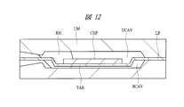
- the lead frame LF on which the semiconductor chip CHP is mounted is sandwiched between the upper mold (first mold) UM and the lower mold (second mold) BM. Note that a cavity UCAV and a cavity BCAV are formed in the upper mold UM and the lower mold BM, respectively.
- the lead frame LF on which the semiconductor chip CHP is mounted has a cavity UCAV between the semiconductor chip CHP and a wire (not shown).
- the chip mounting portion TAB offset to the lower side is positioned so as to be positioned in the cavity BCAV.
- resin RM is inject
- the chip mounting portion TAB is offset downward, and the offset amount is larger than the depth of the cavity BCAV. Therefore, the back surface of the chip mounting portion TAB is the surface (bottom surface) of the cavity BCAV of the lower mold BM. ). As a result, it is possible to prevent the resin RM from entering the back surface of the chip mounting portion TAB.
- the height direction of the chip mounting part TAB is increased.
- the offset amount of the chip mounting portion TAB becomes small, the back surface of the chip mounting portion TAB does not reach (is in close contact) with the surface (bottom surface) of the cavity BCAV of the lower mold BM.
- the resin RM is transferred from the gap formed between the upper surface of the lower mold BM and the back surface of the chip mounting portion TAB to the back surface side of the chip mounting portion TAB. Leaks and enters. Then, the resin burr RB is formed on the back surface of the chip mounting portion TAB that should be exposed. Further, even if the back surface of the chip mounting portion TAB reaches the surface (bottom surface) of the cavity BCAV, if the pressing force to the surface (bottom surface) of the cavity BCAV by the chip mounting portion TAB is weak, the injection pressure of the resin RM As a result, the chip mounting portion TAB floats.
- the resin RM wraps around the back surface of the chip mounting portion TAB, and the resin burr RB is formed on the back surface of the chip mounting portion TAB. It can be seen that the resin burr RB is generated on the back surface of the chip mounting portion TAB by the mechanism as described above.
- FIG. 13 is a diagram illustrating a state in which the resin RM is injected while the laminate sheet LAF is disposed on the upper surface of the lower mold BM.
- the offset chip mounting portion TAB bites into the laminate sheet LAF, so that the resin RM wraps around the back surface of the chip mounting portion TAB. This can be prevented.
- FIG. 13 shows that when the laminate sheet LAF is arranged on the upper surface of the lower mold BM, the offset chip mounting portion TAB bites into the laminate sheet LAF, so that the resin RM wraps around the back surface of the chip mounting portion TAB. This can be prevented.
- FIG. 13 is a diagram illustrating a state in which the resin RM is injected while the laminate sheet LAF is disposed on the upper surface of the lower mold BM.
- the lower mold BM has irregularities, and when the laminate sheet LAF is arranged along the irregularities, when the resin RM is injected, the laminate sheet LAF is caused by the irregularities of the lower mold BM.
- the resin RM enters between the lower mold BM and the laminate sheet LAF from the torn part. That is, since the surface of the lower mold BM for forming the semiconductor device SA1 having the package form QFP is not flat, when the laminate sheet LAF is disposed on the upper surface of the lower mold BM and the resin RM is injected, the laminate sheet LAF is stressed and broken. From this, it can be seen that when the semiconductor device SA1 having the package form QFP is formed, the countermeasure using the laminate sheet LAF does not work effectively.
- FIG. 14A is a cross-sectional view showing how the resin burr RB is removed by the water jet
- FIG. 14B is a plan view showing how the resin burr RB is removed by the water jet. As shown in FIGS. 14A and 14B, it can be seen that the resin burr RB formed on the back surface of the chip mounting portion TAB is removed by the water jet.
- the method of removing the resin burr RB by the water jet method has the following problems. That is, in the water jet method, the resin burr RB having a thickness of about 10 ⁇ m can be removed. However, the resin burr RB having a thickness of about 20 ⁇ m to 30 ⁇ m cannot be completely removed. Further, since the water jet is used to remove the resin burrs RB, water enters the semiconductor device SA1 from the interface between the side surface of the chip mounting portion TAB and the resin RM and is mounted on the chip mounting portion TAB. There is a concern that the semiconductor chip may be corroded. That is, the method of removing the resin burr RB by the water jet method is not desirable from the viewpoint of ensuring the moisture resistance of the semiconductor device SA1.
- FIG. 15A is a cross-sectional view showing how the resin burr RB is removed by gliding (grinding)
- FIG. 15B is a plan view showing how the resin burr RB is removed by gliding (grinding). is there.
- FIGS. 15A and 15B it can be seen that the resin burr RB formed on the back surface of the chip mounting portion TAB is removed by grinding the back surface of the chip mounting portion TAB.
- the method of removing the resin burr RB by the grinding method has the following problems. That is, in the grinding method, it is necessary to grind until the resin burr RB is completely removed, and not only the resin burr RB but also the chip mounting part TAB itself is cut. As a result, there is a problem that the thickness of the chip mounting portion TAB becomes thinner than a preset design value. Further, since the grinding method is a method of removing the resin burrs RB by physical grinding, a large mechanical stress is generated at the interface between the side surface of the chip mounting portion TAB and the resin RM, and the side surface of the chip mounting portion TAB and the resin. The possibility that the interface of RM peels increases. For this reason, there is a concern that moisture may enter the semiconductor device SA1 from the interface between the side surface of the chip mounting portion TAB and the resin RM and corrode the semiconductor chip mounted on the chip mounting portion TAB.
- both the water jet method and the grinding method described above are technologies for removing the resin burr RB by a physical method, and give a large physical stress to the interface between the side surface of the chip mounting portion TAB and the resin RM.
- the present inventor has devised to remove the resin burr RB formed on the back surface of the chip mounting portion TAB while improving the moisture resistance of the semiconductor device.
- the technical idea in the first embodiment will be described with reference to the drawings.
- FIG. 16 is a plan view of the semiconductor device SA2 in the first embodiment as viewed from above.
- the semiconductor device SA2 has a rectangular shape, and the upper surface of the semiconductor device SA2 is covered with a resin (sealing body) RM.
- An outer lead OL protrudes outward from the four sides that define the outer shape of the resin RM.
- FIG. 17 is a plan view of the semiconductor device SA2 according to the first embodiment viewed from the back side.
- the chip mounting portion TAB is exposed from the resin (sealing body) RM.
- the heat generated in the semiconductor chip mounted on the chip mounting portion TAB is transferred to the exposed chip mounting portion TAB. It can be efficiently diffused from the back surface to the mounting substrate.
- the back surface of the chip mounting portion TAB is exposed from the back surface of the resin RM (sealing body) as described above.
- the feature of the first embodiment is that the entire back surface of the chip mounting portion TAB is not exposed, but the outer peripheral portion OR of the chip mounting portion TAB is covered with the resin RM.
- the inner peripheral portion IR of the chip mounting portion TAB which is the inner region of the outer peripheral portion OR, is exposed.
- the interface between the side surface of the chip mounting portion TAB and the resin RM is covered with the resin RM formed on the outer peripheral portion OR, so that the interface between the side surface of the chip mounting portion TAB and the resin RM is exposed (exposed).
- moisture or the like can be prevented from entering the semiconductor device SA2 from the interface between the side surface of the chip mounting portion TAB and the resin RM.
- the semiconductor device SA2 in the first embodiment it is possible to improve the moisture resistance while exposing the back surface of the chip mounting portion TAB to improve the heat dissipation characteristics. Since the inner peripheral portion IR of the chip mounting portion TAB is completely exposed, it is possible to avoid poor solder wettability. As a result, it is possible to prevent defective mounting of the semiconductor device SA2 on the mounting substrate. it can.
- 18 is a cross-sectional view taken along line AA in FIG.
- the outer peripheral portion OR is covered with the resin RM, and the inner peripheral portion IR is exposed from the resin RM.
- a plating film PF is formed on the inner peripheral portion IR of the chip mounting portion TAB.
- the semiconductor chip CHP is mounted on the upper surface of the chip mounting portion TAB, and the area of the chip mounting portion TAB is larger than the area of the semiconductor chip CHP.
- a pad PD is formed on the main surface of the semiconductor chip CHP, and the pad PD formed on the semiconductor chip CHP is electrically connected to the inner lead IL by a wire W.
- the semiconductor chip CHP, the wire W, and the inner lead IL are covered with the resin RM, and the outer lead OL integrated with the inner lead IL protrudes from the resin RM.
- the outer lead OL protruding from the resin RM is formed in a gull wing shape, and a plating film PF is formed on the surface thereof.
- the plating film PF is formed from, for example, a solder plating film.
- the chip mounting portion TAB, the inner lead IL, and the outer lead OL are made of, for example, a copper material or 42 alloy (42 ⁇ Alloy) that is an alloy of iron and nickel, and the wire W is, for example, a gold wire Or copper wire.
- the semiconductor chip CHP is made of, for example, silicon or a compound semiconductor (GaAs or the like), and a plurality of semiconductor elements such as MOSFETs are formed on the semiconductor chip CHP.
- a multilayer wiring is formed above the semiconductor element via an interlayer insulating film, and a pad PD connected to the multilayer wiring is formed on the uppermost layer of the multilayer wiring. Therefore, the semiconductor element formed on the semiconductor chip CHP is electrically connected to the pad PD via the multilayer wiring.
- the integrated circuit is formed by the semiconductor elements formed on the semiconductor chip CHP and the multilayer wiring, and the pads PD function as terminals that connect the integrated circuit and the outside of the semiconductor chip CHP.
- the pad PD is connected to the inner lead IL by a wire W, and is connected to an outer lead OL formed integrally with the inner lead IL. Therefore, the integrated circuit formed on the semiconductor chip CHP can be electrically connected to the outside of the semiconductor device SA2 through the path of the pad PD ⁇ the wire W ⁇ the inner lead IL ⁇ the outer lead OL ⁇ the external connection device. I understand that I can do it.
- the integrated circuit formed on the semiconductor chip CHP can be controlled by inputting an electric signal from the outer lead OL formed on the semiconductor device SA2. It can also be seen that the output signal from the integrated circuit can be taken out from the outer lead OL.
- FIG. 19 is an enlarged cross-sectional view of the area AR in FIG.
- the upper surface of the chip mounting portion TAB is covered with a resin RM.
- the back surface of the chip mounting portion TAB is divided into an outer peripheral portion OR and an inner peripheral portion IR that is an inner region of the outer peripheral portion OR, and the outer peripheral portion OR is covered with the resin RM. IR is exposed.
- a plating film PF made of, for example, a solder plating film is formed on the exposed inner peripheral portion IR of the chip mounting portion TAB.
- the side surface of the chip mounting portion TAB and the resin RM is covered with the resin RM formed on the outer peripheral portion OR, the side surface of the chip mounting portion TAB and the resin RM The interface of is never exposed. Therefore, moisture or the like can be prevented from entering the semiconductor device SA2 from the interface between the side surface of the chip mounting portion TAB and the resin RM.
- the thickness of the chip mounting portion TAB is, for example, about 0.125 mm
- the thickness of the resin RM that wraps around the back surface of the chip mounting portion TAB is, for example, about 0.02 mm to 0.03 mm. is there.
- the length of the outer peripheral portion OR covered with the resin RM is, for example, about 0.2 mm to 0.4 mm. The length of the outer peripheral portion OR covered with the resin RM is determined to have a value sufficiently larger than the alignment accuracy for setting the boundary position with the inner peripheral portion IR from which the resin RM is removed.
- the length of the outer peripheral portion OR covered with the resin RM is made shorter than the alignment accuracy for setting the boundary position between the outer peripheral portion OR and the inner peripheral portion IR, the outer peripheral portion OR is caused by the alignment error. This is because the resin RM is not covered and the interface between the side surface of the chip mounting portion TAB and the resin RM is exposed. Therefore, the length of the outer peripheral portion OR covered with the resin RM is sufficiently larger than the alignment accuracy so that the interface between the side surface of the chip mounting portion TAB and the resin RM is not exposed due to the alignment error. It is decided to have a value.
- the length (0.2 mm to 0.4 mm) of the outer peripheral portion OR covered with the resin RM becomes thicker than the thickness (0.125 mm) of the chip mounting portion TAB. Then, by sufficiently securing the length of the outer peripheral portion OR covered with the resin RM, it is possible to effectively prevent moisture and the like from entering the semiconductor device SA2.
- the position of the lower surface (rear surface) of the resin (sealing body) RM is the position of the chip mounting portion TAB in the thickness (height) direction of the semiconductor device SA2. It can also be expressed as different from the position of the back side. Furthermore, the position of the lower surface (back surface) of the resin (sealing body) RM can also be expressed as being located lower (downward) than the position of the back surface of the chip mounting portion TAB.
- the position of the surface of the plating film PF is lower (lower) than the position of the back surface of the chip mounting portion TAB and is the same as or higher than (upper) the position of the lower surface (back surface) of the resin (sealing body) RM. ) Can also be expressed. That is, the surface of the plating film PF formed on the back surface of the chip mounting portion TAB is the same as the bottom surface (back surface) of the resin (sealing body) RM when viewed from the bottom surface (back surface) of the resin (sealing body) RM. Or in a recessed position.
- FIG. 20 is an enlarged cross-sectional view of the region BR of FIG.
- the flatness of the boundary shape BL1 of the resin RM (sealing body) formed at the boundary between the outer peripheral portion OR and the inner peripheral portion IR is the resin It is rougher than the flatness of the bottom shape BL2 of the RM (sealing body). This is a trace that is inevitably generated when a laser irradiation technique described later is carried out in order to leave the resin RM formed on the outer peripheral portion OR and remove the resin RM formed on the inner peripheral portion IR. is there.
- the semiconductor device SA2 in the first embodiment is configured as described above, and the manufacturing method thereof will be described below with reference to the drawings.
- FIG. 21 is a flowchart showing a flow of a process for manufacturing a package after forming an integrated circuit on the semiconductor chip CHP.
- 22 to 27 are cross-sectional views during the manufacturing process taken along line BB in FIG.
- a lead frame LF processed so that the position of the chip mounting portion TAB is offset downward is prepared.
- the lead frame LF is mainly made of copper here.
- the semiconductor chip CHP is mounted on the chip mounting portion TAB (S201 in FIG. 21).
- the pads and leads of the semiconductor chip CHP are connected by wires (S202 in FIG. 21).
- the lead frame LF on which the semiconductor chip CHP is mounted is sandwiched between the upper mold (first mold) UM and the lower mold (second mold) BM.
- a cavity UCAV and a cavity BCAV are respectively formed in the upper mold UM and the lower mold BM, and the lead frame LF on which the semiconductor chip CHP is mounted has a cavity UCAV between the semiconductor chip CHP and a wire (not shown).
- the chip mounting portion TAB which is positioned inward and offset downward, is aligned so as to be positioned in the cavity BCAV.
- resin RM is inject
- the chip mounting portion TAB is offset downward, but the back surface of the chip mounting portion TAB does not reach the upper surface of the lower mold BM. That is, a gap is formed between the back surface of the chip mounting portion TAB and the upper surface of the lower mold BM.
- the resin RM when the resin RM is continuously injected, the resin RM flows into the front surface (chip mounting surface) side of the chip mounting portion TAB, and the back surface of the chip mounting portion TAB and the upper surface of the lower mold BM. Resin RM also flows into the gap between the two. Thereafter, as shown in FIG. 27, the sealing body made of the resin RM is formed by continuously injecting the resin RM (S203 in FIG. 21).
- the first embodiment is characterized in that the resin RM is actively introduced also to the back surface side of the chip mounting portion TAB.
- the resin RM after cutting a dam (not shown) formed in the lead frame LF (S204 in FIG. 21), the resin RM (resin burr) formed on the back surface of the chip mounting portion TAB is removed (FIG. 21). S205).
- FIG. 28A is a cross-sectional view showing how the resin RM (resin burr) formed on the back surface of the chip mounting portion TAB is removed in the first embodiment
- FIG. It is a top view which shows a mode that resin RM (resin burr
- FIG. 29 is a plan view seen from the back side of the chip mounting portion TAB after resin sealing.
- the resin RM formed on the back surface side of the chip mounting portion TAB is irradiated with a laser pulse, and this laser pulse is scanned over the inner peripheral portion of the chip mounting portion TAB.
- the resin RM is irradiated with a laser pulse
- the resin RM containing carbon as a main component is carbonized by heat generated by irradiating the laser pulse to become “soot” or evaporated.
- the resin RM can be removed without damaging the chip mounting portion TAB.
- the chip mounting portion TAB is scanned by irradiating only the inner peripheral portion IR of the chip mounting portion TAB without irradiating the outer peripheral portion OR of the chip mounting portion TAB with the laser pulse.
- the resin RM (resin burr) formed on the inner periphery IR of the chip mounting portion TAB can be removed while the resin RM (resin burr) remains in the outer periphery OR.
- the area of the back surface of the chip mounting portion TAB exposed from the resin RM (sealing body) is smaller than the area of the chip mounting portion TAB.
- the outer peripheral part OR which comprises a part of back surface of the chip mounting part TAB is covered with resin RM which comprises a sealing body.
- a YAG laser or a carbon dioxide laser (CO 2 laser) can be used as the irradiated laser pulse.
- the resin RM resin burr
- the resin RM is removed by carbonization or evaporation by irradiating the resin RM with a laser pulse. This means that the resin RM formed on the back surface of the chip mounting portion TAB can be removed without applying mechanical stress.
- the resin RM formed on the inner peripheral portion IR can be removed without applying mechanical stress to the interface between the side surface of the chip mounting portion TAB and the resin RM. Accordingly, the resin RM formed on the inner peripheral portion IR on the back surface of the chip mounting portion TAB is prevented while preventing the chip mounting portion TAB and the resin RM from being separated at the interface between the side surface of the chip mounting portion TAB and the resin RM. Can be removed.
- liquid such as moisture is not used when removing the resin RM (resin burr) unlike the water jet method. For this reason, in the first embodiment, moisture enters the semiconductor chip from the interface between the side surface of the chip mounting portion TAB and the resin RM and prevents the semiconductor chip mounted on the chip mounting portion TAB from being corroded. There is also an advantage that can be done.
- the resin RM formed on the outer peripheral portion OR on the back surface of the chip mounting portion TAB is intentionally left and formed on the inner peripheral portion IR on the back surface of the chip mounting portion TAB. Resin RM is removed.
- the interface between the side surface of the chip mounting portion TAB and the resin RM is covered with the resin RM remaining in the outer peripheral portion OR.
- the side surface of the chip mounting portion TAB and the resin are further combined with the effect of adopting a method of removing the resin RM by a laser pulse that does not give mechanical stress and does not require the use of liquid. While preventing the chip mounting portion TAB and the resin RM from being peeled at the interface with the RM, it is possible to obtain a remarkable effect that can prevent moisture from entering from the interface between the side surface of the chip mounting portion TAB and the resin RM.
- the sealing body is formed so that the entire back surface of the chip mounting portion TAB is covered with the resin RM.
- the resin RM (resin burr) is surely formed in the portion corresponding to the outer peripheral portion OR of the chip mounting portion TAB.
- the amount of “soot” when the resin RM is irradiated with the laser pulse is reduced, contamination of the semiconductor device SA2 can be suppressed.
- the laser pulse is applied to the resin RM (resin burr) as a method of removing the resin RM (resin burr) formed on the inner peripheral portion IR on the back surface of the chip mounting portion TAB.
- the trace by adopting the method of irradiating the resin RM (resin burr) with this laser pulse remains in the boundary region between the outer peripheral portion OR and the inner peripheral portion IR. Below, this trace is demonstrated.
- FIG. 32 is an enlarged view showing a region CR in FIG.
- the resin RM (resin burr) formed in the inner peripheral portion IR is removed by scanning a circular laser pulse.
- the boundary shape BL3 between the outer peripheral portion OR where the resin RM (resin burr) remains and the inner peripheral portion IR where the resin RM (resin burr) is removed is shown in FIG.
- FIG. 32 it can be seen that a plurality of arcs are continuously arranged (large waveform shape).
- the boundary shape BL3 between the outer peripheral portion OR where the resin RM (resin burr) remains and the inner peripheral portion IR where the resin RM (resin burr) is removed has a medium scanning pitch of a circular laser pulse, As shown in FIG. 33, it turns out that it becomes the shape (small waveform shape) in which the several circular arc was located in a row.
- the outer peripheral portion OR where the resin RM (resin burr) remains and the inner peripheral portion IR where the resin RM (resin burr) is removed are arranged. It can be seen that the boundary shape BL3 is substantially linear.
- the boundary shape BL3 between the outer peripheral portion OR where the resin RM (resin burr) remains and the inner peripheral portion IR where the resin RM (resin burr) is removed changes according to the scanning pitch of the circular laser pulse.
- the scanning pitch is increased, the waveform shape becomes large and uneven, and as the scanning pitch is reduced, the waveform shape becomes small and uneven. Further, when the scanning pitch is reduced, the waveform becomes almost linear. I understand.
- the boundary shape BL3 between the outer peripheral portion OR where the resin RM (resin burr) remains and the inner peripheral portion IR where the resin RM (resin burr) is removed has a waveform shape.
- the planar shape of the boundary region between the outer peripheral portion OR and the inner peripheral portion IR has been described above.
- the cross-sectional shape of the boundary region between the outer peripheral portion OR and the inner peripheral portion IR also appears as a trace of unevenness.
- the flatness of the boundary shape BL1 of the resin RM (sealing body) formed at the boundary between the outer peripheral portion OR and the inner peripheral portion IR is the bottom shape of the resin RM (sealing body). It becomes rougher than the flatness of BL2.
- the resin RM normally has a configuration in which a binder resin serving as a binder contains a filler made of silica.
- the reason for including the filler in the resin RM is to prevent the warpage of the semiconductor device by causing the resin RM to contain the filler so that the linear expansion coefficient of the resin RM is brought close to the linear expansion coefficient of the semiconductor chip. is there. Therefore, the resin RM usually contains many fillers.
- the filler is formed of, for example, transparent silica
- the resin RM when the resin RM is irradiated with the laser pulse, the laser light passes through the silica.
- the resin RM (binder resin itself) is removed by carbonization or evaporation by irradiation with a laser pulse.
- the resin RM (binder resin itself) is removed, Since silica as a filler remains, the unevenness of the boundary shape BL1 becomes large.
- the flatness of the shape BL1 is rougher than the flatness of the bottom surface shape BL2 of the resin RM (sealing body).
- FIG. 35 is a schematic diagram showing a scanning method SCAN1 in which the inner peripheral portion IR on the back surface of the chip mounting portion TAB is scanned with a laser pulse.
- this scanning method SCAN1 is an example in which a laser pulse is scanned in a rectangular shape.
- the finished degree of removing the resin RM (resin burr) at the inner peripheral portion IR is standard, and there is an advantage that the tact time can be shortened.
- FIG. 36 is a schematic diagram showing a scanning method SCAN2 in which the inner peripheral portion IR on the back surface of the chip mounting portion TAB is scanned with a laser pulse.
- this scanning method SCAN2 is an example in which a laser pulse is scanned in a linear shape.
- the degree of finish of removing the resin RM (resin burr) at the inner peripheral portion IR is beautiful, but the tact time is increased.
- FIG. 37 is a schematic diagram showing a scanning method SCAN3 in which the inner peripheral portion IR on the back surface of the chip mounting portion TAB is scanned with a laser pulse.
- this scanning method SCAN3 is an example in which laser pulses are scanned concentrically.
- the finished degree of removing the resin RM (resin burr) at the inner peripheral portion IR is standard, and the tact time becomes long.
- FIG. 38 is a schematic diagram showing a scanning method SCAN4 in which the inner peripheral portion IR on the back surface of the chip mounting portion TAB is scanned with a laser pulse.
- this scanning method SCAN4 is an example in which scanning is performed by combining an example in which the laser pulse is scanned in a circular shape and an example in which the laser pulse is scanned in a linear shape.
- the finishing degree of removing the resin RM (resin burr) at the inner peripheral portion IR is the most beautiful, but the tact time is increased.
- the scanning methods SCAN1 to SCAN4 described with reference to FIGS. 35 to 38 are examples of scanning methods.
- various scannings are performed in which the irradiation region irradiated with the laser pulse is scanned over the entire region of the inner peripheral portion IR.
- the chip mounting portion TAB has a rectangular shape, and includes a first side, a second side facing the first side, a third side intersecting the first side and the second side, and the third side.
- inner peripheral part IR can be made into the area
- Various methods for scanning the laser pulse over the entire region of the rectangular inner peripheral portion IR are conceivable.
- the scanning time is shortened by using a plurality of laser pulses. It can also be configured. In this manner, the resin RM formed on the inner peripheral portion IR on the back surface of the chip mounting portion TAB can be removed.
- the resin RM (resin burr) remains on the outer peripheral portion OR while the resin RM (resin burr) formed on the inner peripheral portion IR is removed.
- a plating film PF is formed on the back surface (inner peripheral portion IR) of the chip mounting portion TAB exposed from the resin RM and the surface of the lead frame LF (outer lead) (S206 in FIG. 21).
- This plating film PF is formed from, for example, a solder plating film.
- the solder plating film includes, for example, tin-lead plating, pure tin plating that is Pb-free plating, tin-bismuth plating, and the like.
- carbide (soot) generated as a result of irradiating the resin RM formed on the inner peripheral portion IR of the chip mounting portion TAB with laser light, or the back surface of the chip mounting portion TAB.
- the copper oxide film is removed by a pretreatment for plating (a copper oxide film removing process or a water washing process).
- the resin RM resin burr
- the solder in the inner peripheral portion IR is removed. It is possible to avoid poor wettability. As a result, it is possible to significantly reduce mounting defects when mounting the semiconductor device SA2 on the mounting substrate.
- the resin RM is removed by carbonization or evaporation by irradiating the resin RM with a laser pulse.
- the resin RM formed on the back surface of the chip mounting portion TAB can be removed without applying mechanical stress. That is, in the first embodiment, the resin RM formed on the inner peripheral portion IR can be removed without applying mechanical stress to the interface between the side surface of the chip mounting portion TAB and the resin RM. Accordingly, the resin RM formed on the inner peripheral portion IR on the back surface of the chip mounting portion TAB is prevented while preventing the chip mounting portion TAB and the resin RM from being separated at the interface between the side surface of the chip mounting portion TAB and the resin RM. Can be removed.
- the first embodiment is characterized in that the resin RM formed on the outer peripheral portion OR on the back surface of the chip mounting portion TAB is intentionally left and formed on the inner peripheral portion IR on the back surface of the chip mounting portion TAB.
- the resin RM is removed.
- the interface between the side surface of the chip mounting portion TAB and the resin RM is covered with the resin RM remaining in the outer peripheral portion OR.
- the side surface of the chip mounting portion TAB and the resin are further combined with the effect of adopting a method of removing the resin RM by a laser pulse that does not give mechanical stress and does not require the use of liquid. While preventing the chip mounting portion TAB and the resin RM from being peeled at the interface with the RM, it is possible to obtain a remarkable effect that can prevent moisture from entering from the interface between the side surface of the chip mounting portion TAB and the resin RM.
- the chip mounting portion not only during the process of removing the resin RM formed on the back surface of the chip mounting portion TAB, but also after the semiconductor device SA2 is completed, the chip mounting portion.
- the interface between the side surface of the TAB and the resin RM is covered with the resin RM remaining in the outer peripheral portion OR.
- FIG. 42 is a cross-sectional view showing a state in which the semiconductor device SA2 according to the first embodiment is mounted on the mounting substrate SUB.
- the terminal TE1 and the terminal TE2 are formed on the main surface of the mounting substrate SUB.
- the terminal TE1 is exposed to the back surface of the semiconductor device SA2 via the plating film PF and the contact solder PF2.
- a chip mounting portion TAB inner peripheral portion
- the outer lead OL protruding from the sealing body (resin RM) of the semiconductor device SA2 is electrically connected to the terminal TE2 by the solder S.
- the semiconductor device SA2 is mounted on the mounting substrate SUB.
- the back surface (inner peripheral portion) of the chip mounting portion TAB is connected to the terminal TE1 formed on the mounting substrate SUB by heating (reflowing) the soldering solder PF2.
- the resin RM formed on the outer peripheral portion OR on the back surface of the chip mounting portion TAB is intentionally left, it is mounted on the mounting substrate SUB. Even after this, the effect of preventing moisture from entering from the interface between the side surface of the chip mounting portion TAB and the resin RM can be obtained.
- the resin burr removing process (S205), which is a characteristic process according to the first embodiment, is performed after the dam cutting process (S204).
- the resin deburring process can be performed at any position after the molding process (S203) and before the plating process (S206). That is, in the resin burr removing step (S205), which is a characteristic step of the first embodiment, the resin burr formed on the back surface of the chip mounting portion TAB is plated on the back surface of the chip mounting portion TAB in the molding step (S203).
- FIG. 43 is a flowchart showing a flow of a process for manufacturing a package after forming an integrated circuit on a semiconductor chip.
- 44 to 49 are cross-sectional views during the manufacturing process taken along line BB in FIG.
- a lead frame LF processed so that the position of the chip mounting portion TAB is offset downward is prepared.
- This lead frame LF is mainly made of copper, and a plating film PF is formed on the surface thereof.
- This plating film PF is formed of, for example, a nickel film, a palladium film formed on the nickel film, and a gold film formed on the palladium film.
- the semiconductor chip CHP is mounted on the chip mounting portion TAB (S301 in FIG. 43). Then, although not shown in FIG. 46, the pads and leads of the semiconductor chip CHP are connected by wires (S302 in FIG. 43). Thereafter, as shown in FIG.
- the lead frame LF on which the semiconductor chip CHP is mounted is sandwiched between the upper mold UM and the lower mold BM, and the resin RM is injected.
- the chip mounting portion TAB is offset downward, but the back surface of the chip mounting portion TAB does not reach the upper surface of the lower mold BM. That is, a gap is formed between the back surface of the chip mounting portion TAB and the upper surface of the lower mold BM.
- the resin RM when the resin RM is continuously injected, the resin RM flows into the front surface (chip mounting surface) side of the chip mounting portion TAB, and the back surface of the chip mounting portion TAB and the upper surface of the lower mold BM. Resin RM also flows into the gap between the two. Thereafter, as shown in FIG. 49, the sealing body made of the resin RM is formed by continuously injecting the resin RM (S303 in FIG. 43). As described above, the present modification is characterized in that the resin RM is actively introduced also to the back surface side of the chip mounting portion TAB. Then, after cutting a dam (not shown) formed in the lead frame LF (S304 in FIG. 43), the resin RM (resin burr) formed on the back surface of the chip mounting portion TAB is removed (FIG. 43). S305).
- a laser pulse is applied to the resin RM formed on the back surface side of the chip mounting portion TAB, and this laser pulse is mounted on the chip. Scan over the inner periphery of the part TAB.
- the resin RM is irradiated with a laser pulse
- the resin RM containing carbon as a main component is carbonized by heat generated by irradiating the laser pulse to become “soot” or evaporated.
- the resin RM can be removed without damaging the chip mounting portion TAB.
- the resin RM (resin burr) remains on the outer peripheral portion OR, while the resin RM (resin burr) formed on the inner peripheral portion IR is removed.
- carbide (soot) generated as a result of irradiating the resin RM formed on the inner peripheral portion IR of the chip mounting portion TAB with laser light, and the copper oxide film formed on the back surface of the chip mounting portion TAB are oxidized. It is removed by a copper film removal process or a water washing process.
- the step of removing the resin RM (resin burr) formed on the back surface of the chip mounting portion TAB is performed after the molding step. Any stage can be used.
- the position of the lower surface (back surface) of the resin (sealing body) RM is the position of the back surface of the chip mounting portion TAB. It can also be expressed as different from the position. Furthermore, the position of the lower surface (back surface) of the resin (sealing body) RM can also be expressed as being located lower (downward) than the position of the back surface of the chip mounting portion TAB.
- the position of the surface of the plating film PF is lower (lower) than the position of the back surface of the chip mounting portion TAB, and is higher (upper) than the position of the lower surface (back surface) of the resin (sealing body) RM. It can also be expressed as That is, the surface of the plating film PF formed on the back surface of the chip mounting portion TAB is in a recessed position when viewed from the bottom surface (back surface) of the resin (sealing body) RM.
- the semiconductor device SA2 in the first embodiment and the semiconductor device SA2 in the present modification have been described.
- the feature of the semiconductor device SA2 is formed in the outer peripheral portion OR on the back surface of the chip mounting portion TAB.
- the resin RM is intentionally left and the resin RM formed on the inner peripheral portion IR on the back surface of the chip mounting portion TAB is removed.
- FIG. 52 is a diagram showing a state in which common semiconductor devices SA1 are stacked.
- a plating film is formed on the back surface of the chip mounting portion TAB.
- the plating film formed on the back surface of the chip mounting portion TAB of the semiconductor device SA1 disposed in the upper portion is rubbed with the resin RM of the semiconductor device SA1 disposed in the lower portion.
- scratches may occur on the plating film of the semiconductor device SA1 disposed on the upper portion, which may cause poor solder wettability during mounting.
- a plating piece generated by rubbing the plating film of the semiconductor device SA1 disposed in the upper portion adheres to the upper surface of the semiconductor device SA1 disposed in the lower portion, which causes generation of conductive foreign matters.
- FIG. 53 is a diagram showing a state in which the semiconductor devices SA2 in the first embodiment and this modification are stacked and arranged.
- a plating film is formed on the back surface of the chip mounting portion TAB.
- the resin RM formed on the outer peripheral portion OR on the back surface of the chip mounting portion TAB is intentionally left and the inner peripheral portion IR on the back surface of the chip mounting portion TAB.
- the resin RM formed in the step is removed.
- the back surface (inner peripheral portion IR) of the chip mounting portion TAB is recessed, and the plating film formed on the back surface of the chip mounting portion TAB of the semiconductor device SA1 disposed in the upper portion is disposed in the lower portion. It is possible to prevent the semiconductor device SA1 from being rubbed with the resin RM. From this, according to the configuration of the semiconductor device SA2 in the first embodiment and the present modification, the plating film is damaged, resulting in poor solder wettability at the time of mounting, and a conductive film made of a plated piece. It is possible to prevent the generation of sexual foreign substances.
- the size (area) of the chip mounting portion TAB is larger than the size (area) of the semiconductor chip CHP.
- the technical idea of the present invention is not limited to this.
- the present invention can also be applied to the device SA2.
- FIG. 54 a semiconductor having a configuration in which the size (area) of the chip mounting portion TAB2 is smaller than the size (area) of the semiconductor chip CHP.
- the structure is such that moisture can easily enter the semiconductor chip.
- the resin RM formed on the outer peripheral portion OR on the back surface of the chip mounting portion TAB2 is intentionally left and the inner peripheral portion IR on the back surface of the chip mounting portion TAB2 is used.
- the resin RM formed in the step is removed.
- FIG. 55 is a plan view of the semiconductor device SA3 according to the second embodiment as viewed from above. As shown in FIG. 55, the semiconductor device SA3 has a rectangular shape, and the upper surface of the semiconductor device SA3 is covered with a resin (sealing body) RM.
- a resin coupling body
- FIG. 56 is a plan view of the semiconductor device SA3 according to the second embodiment as viewed from the back surface.
- the chip mounting portion TAB is exposed from the resin (sealing body) RM.
- the heat generated in the semiconductor chip mounted on the chip mounting portion TAB is transferred to the exposed chip mounting portion TAB. It can be efficiently diffused from the back surface to the mounting substrate.
- the back surface of the chip mounting portion TAB is exposed from the back surface of the resin RM (sealing body) as described above.
- the feature of the second embodiment is that the entire back surface of the chip mounting portion TAB is not exposed, and the outer peripheral portion OR of the chip mounting portion TAB is covered with the resin RM.
- the inner peripheral portion IR of the chip mounting portion TAB which is the inner region of the outer peripheral portion OR, is exposed.
- the interface between the side surface of the chip mounting portion TAB and the resin RM is covered with the resin RM formed in the outer peripheral portion OR, the interface between the side surface of the chip mounting portion TAB and the resin RM is not exposed. Absent. For this reason, it is possible to prevent moisture and the like from entering the semiconductor device SA3 from the interface between the side surface of the chip mounting portion TAB and the resin RM.
- the semiconductor device SA3 in the second embodiment it is possible to improve the moisture resistance while exposing the back surface of the chip mounting portion TAB to improve the heat dissipation characteristics. Since the inner peripheral portion IR of the chip mounting portion TAB is completely exposed, it is possible to avoid solder wettability failure. As a result, it is possible to prevent mounting failure of the semiconductor device SA3 on the mounting substrate. it can.
- 57 is a cross-sectional view taken along line AA in FIG.
- the outer peripheral portion OR is covered with the resin RM, and the inner peripheral portion IR is exposed from the resin RM.
- a plating film PF is formed on the inner peripheral portion IR of the chip mounting portion TAB.
- the semiconductor chip CHP is mounted on the upper surface of the chip mounting portion TAB, and the area of the chip mounting portion TAB is larger than the area of the semiconductor chip CHP.
- a pad PD is formed on the main surface of the semiconductor chip CHP, and the pad PD formed on the semiconductor chip CHP is electrically connected to the lead LD by a wire W.
- the upper surfaces of these semiconductor chips CHP, wires W and leads LD are covered with a resin RM.
- the back surface of the lead LD is exposed from the resin RM, and the plating film PF is formed on the back surface of the exposed lead LD.
- the chip mounting portion TAB and the lead LD are made of, for example, copper alloy or 42 alloy (42 Alloy) which is an alloy of iron and nickel, and the wire W is made of, for example, a gold wire or a copper wire.
- the semiconductor chip CHP is made of, for example, silicon or a compound semiconductor (GaAs or the like), and a plurality of semiconductor elements such as MOSFETs are formed on the semiconductor chip CHP.
- a multilayer wiring is formed above the semiconductor element via an interlayer insulating film, and a pad PD electrically connected to the multilayer wiring is formed on the uppermost layer of the multilayer wiring. Therefore, the semiconductor element formed in the semiconductor chip CHP is connected to the pad PD via the multilayer wiring.
- An integrated circuit is formed by a semiconductor element formed on the semiconductor chip CHP and a multilayer wiring, and a pad PD functions as a terminal connecting the integrated circuit and the outside of the semiconductor chip CHP.
- the pad PD is connected to the lead LD by a wire W.
- the semiconductor device SA3 according to the second embodiment is configured as described above, and the manufacturing method thereof will be described below with reference to the drawings.
- FIG. 58 is a flowchart showing a flow of a process for manufacturing a package after forming an integrated circuit on the semiconductor chip CHP.
- 59 to 68 are cross-sectional views in the manufacturing process taken along line BB in FIG.
- a lead frame LF processed so that the position of the chip mounting portion TAB is offset upward is prepared.
- This lead frame LF is mainly made of copper.
- the semiconductor chip CHP is mounted on the chip mounting portion TAB (S401 in FIG. 58).
- the pads and leads of the semiconductor chip CHP are connected by wires (S402 in FIG. 58).
- the lead frame LF on which the semiconductor chip CHP is mounted is sandwiched between the upper mold UM and the lower mold BM, and the resin RM is injected.
- the chip mounting portion TAB is offset upward, a gap is formed between the back surface of the chip mounting portion TAB and the upper surface of the lower mold BM.
- the resin RM flows into the front surface (chip mounting surface) side of the chip mounting portion TAB, and the back surface of the chip mounting portion TAB and the upper surface of the lower mold BM. Resin RM also flows into the gap between the two.
- the sealing body made of the resin RM is formed by continuously injecting the resin RM (S403 in FIG. 58).
- the lead frame LF on which the sealing body is formed is taken out from the mold.
- the second embodiment is characterized in that the resin RM is actively introduced to the back side of the chip mounting portion TAB.
- a laser pulse is applied to the resin RM formed on the back surface side of the chip mounting portion TAB, and this laser pulse is mounted on the chip. Scan over the inner periphery of the part TAB.
- the resin RM is irradiated with a laser pulse
- the resin RM containing carbon as a main component is carbonized by heat generated by irradiating the laser pulse to become “soot” or evaporated.
- the resin RM can be removed without damaging the chip mounting portion TAB.
- the resin RM (resin burr) remains on the outer peripheral portion OR, while the resin RM formed on the inner peripheral portion IR. (Resin burrs) are removed. Thereafter, as shown in FIG. 67, a plating film PF is formed on the back surface (inner peripheral portion IR) of the chip mounting portion TAB exposed from the resin RM and on the surface of the lead frame LF (S406 in FIG. 58).
- This plating film PF is formed from, for example, a solder plating film.
- the copper oxide film is removed by a pretreatment for plating (a copper oxide film removing process or a water washing process).
- the lead frame LF is cut (S408 in FIG. 58).
- an electrical characteristic inspection is performed (S409 in FIG. 58), and only the semiconductor device SA3 determined to be non-defective is shipped as a product.
- the structure of the second embodiment is characterized in that the position of the lower surface (back surface) of the resin (sealing body) RM is the position of the chip mounting portion TAB in the thickness (height) direction of the semiconductor device SA3. It can also be expressed as different from the position of the back side. Furthermore, the position of the lower surface (back surface) of the resin (sealing body) RM can also be expressed as being located lower (downward) than the position of the back surface of the chip mounting portion TAB.
- the position of the surface of the plating film PF is lower (lower) than the position of the back surface of the chip mounting portion TAB and is the same as or higher than (upper) the position of the lower surface (back surface) of the resin (sealing body) RM. ) Can also be expressed. That is, the surface of the plating film PF formed on the back surface of the chip mounting portion TAB is the same as the bottom surface (back surface) of the resin (sealing body) RM when viewed from the bottom surface (back surface) of the resin (sealing body) RM. Or in a recessed position.
- the same effect as that of the semiconductor device SA2 in the first embodiment can be obtained.
- the resin RM formed on the outer peripheral portion OR on the back surface of the chip mounting portion TAB is intentionally left as in the first embodiment, and the chip mounting portion TAB The resin RM formed on the inner peripheral portion IR on the back surface is removed.
- the interface between the side surface of the chip mounting portion TAB and the resin RM is covered with the resin RM remaining in the outer peripheral portion OR.
- the side surface of the chip mounting portion TAB and the resin are further combined with the effect of adopting a method of removing the resin RM by a laser pulse that does not give mechanical stress and does not require the use of liquid. While preventing the chip mounting portion TAB and the resin RM from being peeled at the interface with the RM, it is possible to obtain a remarkable effect that can prevent moisture from entering from the interface between the side surface of the chip mounting portion TAB and the resin RM.
- the resin is left on the outer peripheral portion on the back surface of the chip mounting portion, and the resin is also left on the outer peripheral portion of the lead depending on the size and pitch of the lead. An example divided into cases will be described.
- a lead frame LF processed so that the position of the chip mounting portion TAB and the position of the lead are offset above the position of a tab suspension lead (not shown) is prepared.
- This lead frame LF is mainly made of copper.
- the semiconductor chip CHP is mounted on the chip mounting portion TAB.
- Pads PD are formed on the main surface (upper surface) of the semiconductor chip CHP.
- the pads PD and leads of the semiconductor chip CHP are connected by wires W.
- the lead frame LF on which the semiconductor chip CHP is mounted is sealed with a resin RM.
- the resin RM is formed so as to wrap around the back surface of the chip mounting portion TAB and the back surface of the lead.
- the resin RM (resin burr) formed on the back surface of the chip mounting portion TAB and the back surface of the lead LD is removed.
- a laser is applied to the resin RM formed on the back surface side of the chip mounting portion TAB and the back surface side of the lead LD.
- a pulse is irradiated, and this laser pulse is scanned over the inner periphery of the chip mounting portion TAB and the inner periphery of the lead LD.
- the resin RM When the resin RM is irradiated with a laser pulse, the resin RM containing carbon as a main component is carbonized by heat generated by irradiating the laser pulse to become “soot” or evaporated. On the other hand, since the copper constituting the chip mounting portion TAB and the lead LD almost reflects the laser beam, the resin RM can be removed without damaging the chip mounting portion TAB and the lead LD.
- the resin RM (resin burr) remains on the outer peripheral portion OR, while the resin RM formed on the inner peripheral portion IR. (Resin burrs) are removed.
- the resin RM (resin burr) remains on the outer periphery OR2, while the resin RM (resin burr) formed on the inner periphery IR2 of the lead LD is removed. .
- FIG. 74 is a cross-sectional view taken along line AA in FIG.
- the resin RM remains in both the outer peripheral portion OR on the back surface of the chip mounting portion TAB and the outer peripheral portion OR2 on the back surface of the lead LD.
- the resin RM is removed in both the inner peripheral portion IR on the back surface of the chip mounting portion TAB and the inner peripheral portion IR2 on the back surface of the lead LD, and the inner peripheral portion IR on the back surface of the chip mounting portion TAB and the lead LD. It can be seen that the inner peripheral portion IR2 on the back surface of is exposed.
- the third embodiment is characterized in that the resin RM remains not only in the outer peripheral portion OR of the back surface of the chip mounting portion TAB but also in the outer peripheral portion OR2 of the back surface of the lead LD.
- the interface between the side surface of the chip mounting portion TAB and the resin RM is covered with the resin RM remaining in the outer peripheral portion OR, and the interface between the side surface of the lead LD and the resin RM is also formed.
- the resin RM remaining in the outer peripheral portion OR2 is covered. From this, the side surface of the chip mounting portion TAB and the resin are further combined with the effect of adopting a method of removing the resin RM by a laser pulse that does not give mechanical stress and does not require the use of liquid.
- the entire back surface of the lead LD is exposed from the viewpoint of securing the mounting strength on the mounting board.
- leaving the resin RM formed on the outer peripheral portion OR2 on the back surface of the lead LD improves the moisture resistance of the semiconductor device SA3. It is effective from the viewpoint of That is, by leaving the resin RM in the outer peripheral portion OR2 on the back surface of the lead LD, it is possible to prevent the separation between the lead LD and the resin RM at the interface between the side surface of the lead LD and the resin RM.
- the moisture resistance of the semiconductor device SA3 can be further improved.
- a plating film PF is applied to the back surface (inner peripheral portion IR) of the chip mounting portion TAB exposed from the resin RM, the back surface of the lead LD (inner peripheral portion IR2), and the surface of the lead frame LF.
- This plating film PF is formed from, for example, a solder plating film.
- the result is that the resin RM formed on the inner peripheral portion IR of the chip mounting portion TAB and the resin RM formed on the inner peripheral portion IR2 of the lead LD are irradiated with laser light.
- the carbide (soot) and the copper oxide film formed on the back surface of the chip mounting portion TAB and the back surface of the lead LD are removed by a pretreatment for plating (a copper oxide film removing step and a water washing step).
- the lead frame LF is cut as shown in FIG. After the semiconductor device SA3 is formed in this way, an electrical characteristic inspection is performed, and only the semiconductor device SA3 that is determined to be non-defective is shipped as a product.
- the resin is left in the outer peripheral portion of the back surface of the chip mounting portion of the third embodiment shown in FIG. 76, and the structural feature in the case where the resin is also left in the outer peripheral portion of the lead is characterized by the thickness (high) of the semiconductor device SA3.
- the position of the lower surface (back surface) of the resin (sealing body) RM can be expressed as being different from the position of the back surface of the chip mounting portion TAB and the position of the back surface of the lead LD.
- the position of the lower surface (back surface) of the resin (sealing body) RM can also be expressed as being located below (downward) the position of the back surface of the chip mounting portion TAB and the position of the back surface of the lead LD.
- the position of the back surface of the chip mounting portion TAB and the position of the back surface of the lead LD are the same. Further, the position of the surface of the plating film PF formed on the back surface of the chip mounting portion TAB and the back surface of the lead LD is lower (downward) than the position of the back surface of the chip mounting portion TAB, and the resin (encapsulation) It can be expressed that it is the same as the position of the lower surface (back surface) of RM or the upper surface (upper surface) of RM.
- the surface of the plating film PF formed on the back surface of the chip mounting portion TAB and on the back surface of the lead LD is made of the resin (sealing body) RM when viewed from the lower surface (back surface) of the resin (sealing body) RM. It is in the same position as the lower surface (back surface) or in a recessed position.
- a lead frame LF processed so that the position of the chip mounting portion TAB is offset above the position of the lead or the position of the tab suspension lead (not shown) is prepared.
- This lead frame LF is mainly made of copper.
- the semiconductor chip CHP is mounted on the chip mounting portion TAB.
- Pads PD are formed on the main surface (upper surface) of the semiconductor chip CHP.
- the pad PD and the lead of the semiconductor chip CHP are connected by the wire W.
- the lead frame LF on which the semiconductor chip CHP is mounted is sealed with a resin RM.
- the resin RM is formed to wrap around the back surface of the chip mounting portion TAB. Further, it is desirable that the resin RM is not formed on the back surface of the lead that is not offset, but the resin RM also wraps around the back surface of the lead to form a resin burr.
- the resin RM (resin burr) formed on the back surface of the chip mounting portion TAB and the back surface of the lead LD is removed.
- a laser is applied to the resin RM formed on the back surface side of the chip mounting portion TAB and the back surface side of the lead LD.
- a pulse is irradiated, and this laser pulse is scanned over the inner periphery of the chip mounting portion TAB and the inner periphery of the lead LD.
- the resin RM When the resin RM is irradiated with the laser pulse, the resin RM containing carbon as a main component is carbonized by the heat generated by the irradiation of the laser pulse to become “soot” or removed by evaporation.
- the resin RM since the copper constituting the chip mounting portion TAB and the lead LD almost reflects the laser beam, the resin RM can be removed without damaging the chip mounting portion TAB and the lead LD.
- the resin RM (resin burr) remains on the outer peripheral portion OR, while the resin RM formed on the inner peripheral portion IR. (Resin burrs) are removed.
- the resin RM (resin burr) formed on the lead LD is removed on the entire back surface of the lead LD.
- the resin RM remains at the outer peripheral portion OR of the back surface of the chip mounting portion TAB.
- the resin RM is removed in both the inner peripheral portion IR on the back surface of the chip mounting portion TAB and the entire back surface of the lead LD, and the inner peripheral portion IR on the back surface of the chip mounting portion TAB and the entire back surface of the lead LD are You can see that it is exposed.
- the size of the lead LD is relatively large, as described above, leaving the resin RM formed on the outer peripheral portion OR2 on the back surface of the lead LD improves the moisture resistance of the semiconductor device SA3. (See FIGS. 73 and 74).
- FIG. 81 when the size of the lead LD is small, the area of the exposed back surface of the lead LD is made as large as possible from the viewpoint of securing the mounting strength on the mounting substrate. Is desirable. Therefore, when the size of the lead LD is small, it is effective to remove the resin RM (resin burr) formed on the back surface of the lead LD to expose the entire back surface of the lead LD. Thereby, the mounting strength of the semiconductor device SA3 on the mounting substrate can be improved.
- a plating film PF is formed on the back surface (inner peripheral portion IR) of the chip mounting portion TAB exposed from the resin RM, the entire back surface of the lead LD, and the surface of the lead frame LF.
- This plating film PF is formed from, for example, a solder plating film.
- carbide (soot) generated as a result of irradiating the resin RM formed on the inner peripheral portion IR of the chip mounting portion TAB and the resin RM formed on the back surface of the lead LD with a laser beam.
- the copper oxide film formed on the back surface of the chip mounting portion TAB and the back surface of the lead LD is removed by a pretreatment for plating (a copper oxide film removal step or a water washing step).
- the lead frame LF is cut as shown in FIG. After the semiconductor device SA3 is formed in this way, an electrical characteristic inspection is performed, and only the semiconductor device SA3 that is determined to be non-defective is shipped as a product.
- the position of the lower surface (back surface) of the resin (sealing body) RM can be expressed as being different from the position of the back surface of the chip mounting portion TAB and the position of the back surface of the lead LD. Furthermore, the position of the lower surface (back surface) of the resin (sealing body) RM is located below (lower) the position of the back surface of the chip mounting portion TAB, and above (upper) the position of the back surface of the lead LD. It can be expressed that it is located at.
- the position of the surface of the plating film PF formed on the back surface of the chip mounting portion TAB and the back surface of the lead LD is lower (downward) than the position of the back surface of the chip mounting portion TAB, and resin (sealing) It can be expressed that it is the same as the position of the lower surface (back surface) of RM or the upper surface (upper surface) of RM. That is, the surface of the plating film PF formed on the back surface of the chip mounting portion TAB and on the back surface of the lead LD is made of the resin (sealing body) RM when viewed from the lower surface (back surface) of the resin (sealing body) RM.
- the surface of the plating film PF formed on the back surface of the lead LD is lower (downward) than the lower surface (back surface) of the resin (sealing body) RM, that is, at a protruding position.
- the semiconductor device mounted with a single semiconductor chip has been described, but the technical idea of the present invention is also applied to, for example, a semiconductor device mounted with a plurality of semiconductor chips. be able to. Below, the example which applies the technical idea of this invention to the semiconductor device which mounts a some semiconductor chip is demonstrated.
- FIG. 85 is a top view showing an external configuration of the semiconductor device SA4. As shown in FIG. 85, the semiconductor device SA4 has a rectangular shape, and the upper surface of the semiconductor device SA4 is covered with a resin (sealing body) RM.
- a resin coupling body
- FIG. 86 is a plan view of the semiconductor device SA4 viewed from the back side. As shown in FIG. 86, the chip mounting portions TAB1A to TAB1C are formed in the semiconductor device SA4, and the chip mounting portions TAB1A to TAB1C are exposed from the resin (sealing body) RM.
- the feature of the semiconductor device SA4 is that, as shown in FIG. 86, the entire back surface of the chip mounting portions TAB1A to TAB1C is not exposed, but the outer peripheral portion OR1A of the chip mounting portion TAB1A is covered with the resin RM.
- the inner peripheral portion IR1A of the chip mounting portion TAB1A that is the inner region of the outer peripheral portion OR1A is exposed.
- the outer peripheral portion OR1B of the chip mounting portion TAB1B is covered with the resin RM, and the inner peripheral portion IR1B of the chip mounting portion TAB1B that is an inner region of the outer peripheral portion OR1B is exposed.
- the outer peripheral portion OR1C of the chip mounting portion TAB1C is covered with the resin RM, and the inner peripheral portion IR1C of the chip mounting portion TAB1C, which is an inner region of the outer peripheral portion OR1C, is exposed.
- the interface between the side surfaces of the chip mounting portions TAB1A to TAB1C and the resin RM is covered with the resin RM formed on the outer peripheral portions OR1A to OR1C, so that the side surfaces of the chip mounting portions TAB1A to TAB1C and the resin RM The interface is not exposed. Therefore, it is possible to prevent moisture and the like from entering the semiconductor device SA4 from the interface between the side surfaces of the chip mounting portions TAB1A to TAB1C and the resin RM.
- the moisture resistance can be improved while exposing the back surfaces of the chip mounting portions TAB1A to TAB1C to improve the heat dissipation characteristics. Since the inner peripheral portions IR1A to IR1C of the chip mounting portions TAB1A to TAB1C are completely exposed, it is possible to avoid poor solder wettability. As a result, the mounting failure of the semiconductor device SA4 to the mounting substrate can be avoided. Can be prevented.
- 87 is a cross-sectional view taken along the line AA in FIG.
- the chip mounting portion TAB1A and the chip mounting portion TAB1B are formed, the semiconductor chip CHP1 is mounted on the chip mounting portion TAB1A, and the semiconductor chip CHP2 is mounted on the chip mounting portion TAB1B. It is installed.
- the back surface of the chip mounting portion TAB1A is divided into the outer peripheral portion OR1A and the inner peripheral portion IR1A, the outer peripheral portion OR1A is covered with the resin RM, and the inner peripheral portion IR1A is exposed from the resin RM, and the exposed chip mounting portion TAB1A is exposed.
- a plating film PF is formed on the inner peripheral portion IR1A.
- the outer peripheral portion OR1B is covered with the resin RM, and the inner peripheral portion IR1B is exposed from the resin RM and is exposed.
- a plating film PF is formed on the inner peripheral portion IR1B of the mounting portion TAB1B.
- the area of the chip mounting portion TAB1A is larger than the area of the semiconductor chip CHP1, and similarly, the area of the chip mounting portion TAB1B is larger than the area of the semiconductor chip CHP2.
- the pads PD are formed on the main surfaces of the semiconductor chip CHP1 and the semiconductor chip CHP2, and the pads PD formed on the semiconductor chip CHP1 and the semiconductor chip CHP2 are electrically connected to the leads LD and the wires W. Yes.
- the semiconductor chip CHP1 and the semiconductor chip CHP2 are electrically connected by, for example, a wire W.
- the upper surfaces of these semiconductor chip CHP1, semiconductor chip CHP2, wire W, and lead LD are covered with resin RM.
- the back surface of the lead LD is exposed from the resin RM, and the plating film PF is formed on the back surface of the exposed lead LD.
- the semiconductor device SA4 is configured as described above. Similarly to the semiconductor devices SA2 to SA3 described in the first to third embodiments, the semiconductor device SA4 is also made from a resin (sealing body) RM to a chip mounting portion TAB (TAB1A). TAB1C) and the lead LD are common in that they have a structure in which a part of the surface is exposed and the surface is soldered. For this reason, the technical idea of the present invention can be applied also to the semiconductor device SA4. As a result, the semiconductor device SA4 also has a remarkable effect that the solder wettability can be ensured while ensuring the moisture resistance. be able to. Specific examples of the semiconductor device SA4 include a SIP (System In Package) product and a power switch.
- SIP System In Package
- MOSFET MetalInsulator Semiconductor Field Effect Transistor
- the plating film PF is formed after removing the resin RM of the chip mounting portion TAB.
- the surface of the lead is previously formed.
- a lead frame on which the plating film PF is formed may be used.
Abstract
Provided is technology that can improve the quality of semiconductor devices by eliminating resin burrs formed on the back surface of a chip mounting part in a semiconductor device where the back surface of the chip mounting part on which a semiconductor chip is mounted is exposed by a sealing body and a method for manufacturing the same. The entire back surface of a chip mounting part (TAB) is not exposed. The peripheral part (OR) of the chip mounting part (TAB) is covered by resin (RM), and the inner peripheral part (IR) of the chip mounting part (TAB), which is the region inside of the peripheral part (OR), is exposed. Thus, the interfaces of the side surfaces of the chip mounting part (TAB) and the resin (RM) are covered by the resin (RM) formed on the peripheral part (OR); therefore, the interfaces of side surfaces of the chip mounting part (TAB) and the resin (RM) are not exposed. Therefore, moisture and the like can be prevented from infiltrating into a semiconductor device (SA2) from the interfaces of the side surfaces of the chip mounting part (TAB) and the resin (RM).
Description
本発明は、半導体装置およびその製造技術に関し、特に、半導体チップを搭載するチップ搭載部の裏面が封止体から露出している半導体装置およびその製造技術に適用して有効な技術に関するものである。
The present invention relates to a semiconductor device and a manufacturing technique thereof, and more particularly to a semiconductor device in which a back surface of a chip mounting portion on which a semiconductor chip is mounted is exposed from a sealing body and a technique effective when applied to the manufacturing technique. .
特開2001-160562号公報(特許文献1)には、ダイパッドの露出面に発生する樹脂バリを効率的に除去するための技術が記載されている。具体的には、ダイパッドの裏面に予めPdメッキを施したリードフレームに、半導体素子を搭載し、樹脂封止する。その後、NaOHとKOHを混合した水溶液による電解液中に、上述したリードフレームを浸漬させて電解洗浄を行なう。これにより、露出面に生じた樹脂バリを短時間で除去することができ、半導体装置の高品質化を図ることができるとしている。
Japanese Patent Laid-Open No. 2001-160562 (Patent Document 1) describes a technique for efficiently removing resin burrs generated on the exposed surface of a die pad. Specifically, a semiconductor element is mounted on a lead frame in which the back surface of the die pad is preliminarily plated with Pd and sealed with resin. Thereafter, the above-described lead frame is immersed in an electrolytic solution of an aqueous solution in which NaOH and KOH are mixed, and electrolytic cleaning is performed. Thereby, resin burrs generated on the exposed surface can be removed in a short time, and the quality of the semiconductor device can be improved.
特開平11-195743号公報(特許文献2)には、樹脂封止体の実装側端面(裏面)を研削することにより、各インナーリードおよびタブの裏面を露出することが記載されている。
JP-A-11-195743 (Patent Document 2) describes that the back surface of each inner lead and tab is exposed by grinding the mounting-side end surface (back surface) of the resin sealing body.
特開2001-127228号公報(特許文献3)には、フレーム枠に樹脂フィルムを備えることにより、封止樹脂の回り込みを防止する技術が記載されている。
Japanese Patent Laid-Open No. 2001-127228 (Patent Document 3) describes a technique for preventing a sealing resin from wrapping around by providing a resin film on a frame.
特開2002-184795号公報(特許文献4)には、パッケージ形態がQFN(Quad Flat Non-leaded package)である半導体装置において、リードの裏面にレーザを照射して、レジンバリを除去する技術が記載されている。
Japanese Laid-Open Patent Publication No. 2002-184895 (Patent Document 4) describes a technique for removing a resin burr by irradiating a laser on the back surface of a lead in a semiconductor device having a package form of QFN (Quad Flat Non-leaded package). Has been.
例えば、パッケージ形態がQFP(Quad Flat Package)やQFNである半導体装置では、チップ搭載部(ダイパッド、タブ(tab))上に半導体チップを搭載し、チップ搭載部の周囲に設けられた複数のリードと、半導体チップ上に形成された複数のパッドとをワイヤで電気的に接続した構造をしている。そして、通常、チップ搭載部、半導体チップ、ワイヤ、および、複数のリードのそれぞれの一部は樹脂からなる封止体で封止される。このように、QFPやQFNなどのパッケージ形態を有する半導体装置において、通常、チップ搭載部は、封止体の内部に配置され、封止体の裏面からは露出していない。ところが、半導体装置の中には、チップ搭載部の裏面(半導体チップの搭載面とは反対側の面)を封止体の裏面から露出するように構成したものがある。このようにチップ搭載部の裏面を封止体から露出させる構造の利点としては、チップ搭載部に搭載した半導体チップで発生した熱を、露出しているチップ搭載部の裏面から実装基板へ効率的に放散させることができることが挙げられる。つまり、例えば、パワーMOSFETなどのように発熱しやすい半導体素子を形成している半導体チップのパッケージ構造では、上述したようにチップ搭載部の裏面が封止体の裏面から露出している構造を取ることにより、半導体チップで発生した熱を効率よく放散させることができるのである。
For example, in a semiconductor device whose package form is QFP (Quad Flat Package) or QFN, a semiconductor chip is mounted on a chip mounting portion (die pad, tab) and a plurality of leads provided around the chip mounting portion. And a plurality of pads formed on the semiconductor chip are electrically connected by wires. In general, a part of each of the chip mounting portion, the semiconductor chip, the wire, and the plurality of leads is sealed with a sealing body made of resin. As described above, in a semiconductor device having a package form such as QFP or QFN, the chip mounting portion is normally disposed inside the sealing body and is not exposed from the back surface of the sealing body. However, some semiconductor devices are configured such that the back surface of the chip mounting portion (the surface opposite to the mounting surface of the semiconductor chip) is exposed from the back surface of the sealing body. As an advantage of the structure in which the back surface of the chip mounting portion is exposed from the sealing body in this way, the heat generated in the semiconductor chip mounted on the chip mounting portion is efficiently transferred from the exposed back surface of the chip mounting portion to the mounting substrate. Can be diffused. That is, for example, a package structure of a semiconductor chip that forms a semiconductor element that easily generates heat, such as a power MOSFET, has a structure in which the back surface of the chip mounting portion is exposed from the back surface of the sealing body as described above. Thus, the heat generated in the semiconductor chip can be efficiently dissipated.
このようにチップ搭載部の裏面が封止体の裏面から露出しているパッケージの製造方法は以下に示すようなものである。すなわち、封止体の形成は、リードフレームをモールド金型で挟み込み、挟み込んだキャビティ(空間)内に樹脂(レジン)を注入することにより、封止体を形成する。このとき、例えば、チップ搭載部は、その裏面に樹脂が浸入しないように、モールド金型(下金型)のキャビティの面(底面)よりもチップ搭載部が低い(深い)位置にくるようにオフセットされている。これにより、チップ搭載部の裏面は下金型のキャビティ面(底面)に押し付けられる(密着する)ように構成されるので、チップ搭載部の裏面に樹脂が浸入することを防止することができる。
The manufacturing method of the package in which the back surface of the chip mounting part is exposed from the back surface of the sealing body is as follows. That is, the sealed body is formed by sandwiching the lead frame with a mold and injecting resin (resin) into the sandwiched cavity (space). At this time, for example, the chip mounting portion is positioned at a position where the chip mounting portion is lower (deeper) than the cavity surface (bottom surface) of the mold (lower mold) so that the resin does not enter the back surface. It is offset. Thereby, since the back surface of the chip mounting portion is configured to be pressed against (adhered to) the cavity surface (bottom surface) of the lower mold, it is possible to prevent the resin from entering the back surface of the chip mounting portion.
ところが、リードフレーム自体におけるチップ搭載部のオフセット量のばらつき、ダイボンディング工程やワイヤボンディング工程といった熱工程を経ることによるリードフレームの変形発生などの要因により、チップ搭載部の高さ方向の位置ばらつきは増大する。特に、チップ搭載部のオフセット量が小さくなった場合、下金型のキャビティの面(底面)にチップ搭載部の裏面が届かなくなる(密着しなくなる)ことが発生する。この状態のままで樹脂を注入すると、下金型の上面とチップ搭載部の裏面との間に形成された隙間からチップ搭載部の裏面側へ樹脂が漏れ出して浸入することになる。すると、本来、露出すべきチップ搭載部の裏面に樹脂が形成されてしまうことになる(樹脂バリ、レジンバリ)。
However, due to factors such as variations in the offset amount of the chip mounting part in the lead frame itself, and lead frame deformation caused by a thermal process such as a die bonding process and a wire bonding process, the position variation in the height direction of the chip mounting part is Increase. In particular, when the offset amount of the chip mounting portion becomes small, the back surface of the chip mounting portion does not reach (is not in close contact with) the surface (bottom surface) of the cavity of the lower mold. If the resin is injected in this state, the resin leaks out and enters the back surface side of the chip mounting portion from the gap formed between the upper surface of the lower mold and the back surface of the chip mounting portion. Then, a resin is originally formed on the back surface of the chip mounting portion to be exposed (resin burr, resin burr).
このような樹脂バリがチップ搭載部の裏面に発生すると、半導体装置を実装基板に実装する際、樹脂バリが実装の阻害要因となり、実装不良を起こす問題点が発生する。つまり、封止体から露出しているチップ搭載部の裏面は、実装基板に半田を介して直接接続されるが、チップ搭載部の裏面に樹脂バリが残存していると、その樹脂バリが残存している部分は半田の濡れ性が低下するので、チップ搭載部の裏面を実装基板へ確実に実装することができなくなってしまう。特に、チップ搭載部の裏面は、半導体装置を実装基板に実装する際に隠れてしまう部分なので、実装の良否を外観検査で確認することが困難である。このため、チップ搭載部の裏面に形成された樹脂バリを確実に除去することが求められている。
If such a resin burr occurs on the back surface of the chip mounting portion, the resin burr becomes a hindrance to mounting when the semiconductor device is mounted on the mounting substrate, which causes a problem of mounting failure. In other words, the back surface of the chip mounting portion exposed from the sealing body is directly connected to the mounting substrate via solder, but if the resin burr remains on the back surface of the chip mounting portion, the resin burr remains. Since the wettability of the solder is lowered in the portion that is being performed, the back surface of the chip mounting portion cannot be reliably mounted on the mounting substrate. In particular, since the back surface of the chip mounting portion is a portion that is hidden when the semiconductor device is mounted on the mounting substrate, it is difficult to confirm whether the mounting is good or not by visual inspection. For this reason, it is required to reliably remove the resin burrs formed on the back surface of the chip mounting portion.
本発明の目的は、半導体チップを搭載するチップ搭載部の裏面が封止体から露出している半導体装置およびその製造技術において、チップ搭載部の裏面に形成される樹脂バリを除去して、半導体装置の品質向上を図ることができる技術を提供することにある。
An object of the present invention is to remove a resin burr formed on the back surface of a chip mounting portion in a semiconductor device in which the back surface of a chip mounting portion on which a semiconductor chip is mounted is exposed from a sealing body, and its manufacturing technology. The object is to provide a technique capable of improving the quality of the apparatus.
本発明の前記ならびにその他の目的と新規な特徴は、本明細書の記述および添付図面から明らかになるであろう。
The above and other objects and novel features of the present invention will be apparent from the description of this specification and the accompanying drawings.
本願において開示される発明のうち、代表的なものの概要を簡単に説明すれば、次のとおりである。
Of the inventions disclosed in this application, the outline of typical ones will be briefly described as follows.
代表的な実施の形態における半導体装置の製造方法は、半導体チップをチップ搭載部に搭載する工程と、前記チップ搭載部の下面の一部を樹脂で覆って封止体を形成する工程と、を有し、前記チップ搭載部の下面領域を構成する外周部と前記外周部の内側領域である内周部において、前記外周部に形成されている前記樹脂を残存させながら、前記内周部に形成されている前記樹脂を除去することを特徴とするものである。
A method of manufacturing a semiconductor device according to a representative embodiment includes a step of mounting a semiconductor chip on a chip mounting portion, and a step of covering a part of the lower surface of the chip mounting portion with a resin to form a sealing body. And forming the inner peripheral portion while leaving the resin formed on the outer peripheral portion in the outer peripheral portion constituting the lower surface region of the chip mounting portion and the inner peripheral portion which is the inner region of the outer peripheral portion. The resin that has been removed is removed.
また、代表的な実施の形態における半導体装置は、チップ搭載部と、前記チップ搭載部の一部を覆う封止体と、を有し、前記チップ搭載部の裏面領域を構成する外周部と前記外周部の内側領域である内周部において、前記外周部は前記樹脂で覆われ、前記内周部は前記樹脂で覆われておらず露出していることを特徴とするものである。
Further, a semiconductor device in a representative embodiment includes a chip mounting portion and a sealing body that covers a part of the chip mounting portion, and an outer peripheral portion that constitutes a back surface region of the chip mounting portion, and In the inner peripheral portion which is an inner region of the outer peripheral portion, the outer peripheral portion is covered with the resin, and the inner peripheral portion is not covered with the resin and is exposed.
本願において開示される発明のうち、代表的なものによって得られる効果を簡単に説明すれば以下のとおりである。
Among the inventions disclosed in the present application, effects obtained by typical ones will be briefly described as follows.
半導体チップを搭載するチップ搭載部の裏面が封止体から露出している半導体装置およびその製造技術において、チップ搭載部の裏面に形成される樹脂バリを除去して、半導体装置の品質向上を図ることができる。
In a semiconductor device in which the back surface of a chip mounting portion on which a semiconductor chip is mounted is exposed from the sealing body and its manufacturing technology, the resin burr formed on the back surface of the chip mounting portion is removed to improve the quality of the semiconductor device. be able to.
以下の実施の形態においては便宜上その必要があるときは、複数のセクションまたは実施の形態に分割して説明するが、特に明示した場合を除き、それらはお互いに無関係なものではなく、一方は他方の一部または全部の変形例、詳細、補足説明等の関係にある。
In the following embodiments, when it is necessary for the sake of convenience, the description will be divided into a plurality of sections or embodiments. However, unless otherwise specified, they are not irrelevant to each other. There are some or all of the modifications, details, supplementary explanations, and the like.
また、以下の実施の形態において、要素の数等(個数、数値、量、範囲等を含む)に言及する場合、特に明示した場合および原理的に明らかに特定の数に限定される場合等を除き、その特定の数に限定されるものではなく、特定の数以上でも以下でもよい。
Further, in the following embodiments, when referring to the number of elements (including the number, numerical value, quantity, range, etc.), especially when clearly indicated and when clearly limited to a specific number in principle, etc. Except, it is not limited to the specific number, and may be more or less than the specific number.
さらに、以下の実施の形態において、その構成要素(要素ステップ等も含む)は、特に明示した場合および原理的に明らかに必須であると考えられる場合等を除き、必ずしも必須のものではないことは言うまでもない。
Further, in the following embodiments, the constituent elements (including element steps and the like) are not necessarily indispensable unless otherwise specified and apparently essential in principle. Needless to say.
同様に、以下の実施の形態において、構成要素等の形状、位置関係等に言及するときは、特に明示した場合および原理的に明らかにそうではないと考えられる場合等を除き、実質的にその形状等に近似または類似するもの等を含むものとする。このことは、上記数値および範囲についても同様である。
Similarly, in the following embodiments, when referring to the shape, positional relationship, etc., of components, etc., unless otherwise specified, and in principle, it is considered that this is not clearly the case, it is substantially the same. Including those that are approximate or similar to the shape. The same applies to the above numerical values and ranges.
また、実施の形態を説明するための全図において、同一の部材には原則として同一の符号を付し、その繰り返しの説明は省略する。なお、図面をわかりやすくするために平面図であってもハッチングを付す場合がある。
In all the drawings for explaining the embodiments, the same members are, in principle, given the same reference numerals, and the repeated explanation thereof is omitted. In order to make the drawings easy to understand, even a plan view may be hatched.
(実施の形態1)
半導体装置は、MOSFET(Metal Oxide Semiconductor Field Effect Transistor)などの半導体素子と多層配線を形成した半導体チップと、この半導体チップを覆うように形成されたパッケージから形成されている。パッケージには、(1)半導体チップに形成されている半導体素子と外部回路とを電気的に接続するという機能や、(2)湿度や温度などの外部環境から半導体チップを保護し、振動や衝撃による破損や半導体チップの特性劣化を防止する機能がある。さらに、パッケージには、(3)半導体チップのハンドリングを容易にするといった機能や、(4)半導体チップの動作時における発熱を放散し、半導体素子の機能を最大限に発揮させる機能なども合わせもっている。このような機能を有するパッケージには様々な種類が存在する。以下に、パッケージの構成例について説明する。 (Embodiment 1)
2. Description of the Related Art A semiconductor device is formed of a semiconductor element such as a MOSFET (Metal Oxide Semiconductor Field Effect Transistor) and a semiconductor chip in which a multilayer wiring is formed, and a package formed so as to cover the semiconductor chip. The package includes (1) a function of electrically connecting a semiconductor element formed on the semiconductor chip and an external circuit, and (2) protection of the semiconductor chip from an external environment such as humidity and temperature, and vibration and shock. It has a function of preventing damage caused by the semiconductor device and deterioration of the characteristics of the semiconductor chip. In addition, the package has (3) the function of facilitating the handling of the semiconductor chip, and (4) the function of radiating the heat generated during the operation of the semiconductor chip and maximizing the function of the semiconductor element. Yes. There are various types of packages having such functions. Below, the structural example of a package is demonstrated.
まず、一般的な半導体装置の構成について図面を参照しながら説明する。本実施の形態1で説明する半導体装置のパッケージ形態は、QFPである。図1は、一般的な半導体装置SA1を上面から見た平面図である。図1に示すように、半導体装置SA1は矩形形状をしており、半導体装置SA1の上面は樹脂(封止体)RMで覆われている。そして、樹脂RMの外形を規定する四辺から外側に向ってアウターリードOLが突き出ている。
First, the structure of a general semiconductor device will be described with reference to the drawings. The package form of the semiconductor device described in the first embodiment is QFP. FIG. 1 is a plan view of a general semiconductor device SA1 as viewed from above. As shown in FIG. 1, the semiconductor device SA1 has a rectangular shape, and the upper surface of the semiconductor device SA1 is covered with a resin (sealing body) RM. An outer lead OL protrudes outward from the four sides that define the outer shape of the resin RM.
図2は、一般的な半導体装置SA1を裏面から見た平面図である。図2に示すように、チップ搭載部(ダイパッド、タブ)TABが樹脂(封止体)RMから露出している。このようにチップ搭載部TABの裏面を樹脂RM(封止体)から露出させる構造の利点としては、チップ搭載部TABに搭載した半導体チップで発生した熱を、露出しているチップ搭載部TABの裏面から実装基板へ効率的に放散させることができることが挙げられる。つまり、例えば、パワーMOSFETなどのように発熱しやすい半導体素子を形成している半導体チップのパッケージ構造では、上述したようにチップ搭載部TABの裏面が樹脂RM(封止体)の裏面から露出している構造を取ることにより、半導体チップで発生した熱を効率よく放散させることができる。
FIG. 2 is a plan view of a general semiconductor device SA1 viewed from the back side. As shown in FIG. 2, the chip mounting portion (die pad, tab) TAB is exposed from the resin (sealing body) RM. As described above, as an advantage of the structure in which the back surface of the chip mounting portion TAB is exposed from the resin RM (sealing body), the heat generated in the semiconductor chip mounted on the chip mounting portion TAB is transferred to the exposed chip mounting portion TAB. It can be efficiently diffused from the back surface to the mounting substrate. That is, for example, in a semiconductor chip package structure in which a semiconductor element that easily generates heat such as a power MOSFET is formed, the back surface of the chip mounting portion TAB is exposed from the back surface of the resin RM (sealing body) as described above. By adopting such a structure, heat generated in the semiconductor chip can be efficiently dissipated.
図3は、半導体装置SA1を側面から見た図である。図3に示すように、樹脂RMから突き出ているアウターリードOLはガルウィング形状に成形されており、このアウターリードの表面には、例えば、半田めっき膜からなるめっき膜PFが形成されている。続いて、半導体装置SA1の内部構造について説明する。図4は、図1のA-A線で切断した断面図である。図4に示すように、チップ搭載部TABの裏面が樹脂RMから露出しており、露出しているチップ搭載部TABの裏面にめっき膜PFが形成されている。一方、チップ搭載部TABの上面には半導体チップCHPが搭載されており、半導体チップCHPの主面にはパッドPDが形成されている。そして、半導体チップCHPに形成されているパッドPDは、インナーリードILとワイヤWで電気的に接続されている。これらの半導体チップCHP、ワイヤWおよびインナーリードILは樹脂RMで覆われており、インナーリードILと一体化しているアウターリードOLが樹脂RMから突き出ている。樹脂RMから突き出ているアウターリードOLは、ガルウィング形状に成形されており、その表面にめっき膜PFが形成されている。
FIG. 3 is a side view of the semiconductor device SA1. As shown in FIG. 3, the outer lead OL protruding from the resin RM is formed in a gull wing shape, and a plating film PF made of, for example, a solder plating film is formed on the surface of the outer lead. Subsequently, the internal structure of the semiconductor device SA1 will be described. 4 is a cross-sectional view taken along line AA in FIG. As shown in FIG. 4, the back surface of the chip mounting portion TAB is exposed from the resin RM, and the plating film PF is formed on the back surface of the exposed chip mounting portion TAB. On the other hand, a semiconductor chip CHP is mounted on the upper surface of the chip mounting portion TAB, and a pad PD is formed on the main surface of the semiconductor chip CHP. The pad PD formed on the semiconductor chip CHP is electrically connected to the inner lead IL by the wire W. The semiconductor chip CHP, the wire W, and the inner lead IL are covered with the resin RM, and the outer lead OL integrated with the inner lead IL protrudes from the resin RM. The outer lead OL protruding from the resin RM is formed in a gull wing shape, and a plating film PF is formed on the surface thereof.
チップ搭載部TAB、インナーリードIL、および、アウターリードOLは、例えば、銅材や鉄とニッケルとの合金である42アロイ(42 Alloy)などから形成されており、ワイヤWは、例えば、金線や銅線などから形成されている。半導体チップCHPは、例えば、シリコンや化合物半導体(GaAsなど)から形成されており、この半導体チップCHPには、MOSFETなどの複数の半導体素子が形成されている。そして、半導体素子の上方に層間絶縁膜を介して多層配線が形成されており、この多層配線の最上層に多層配線と接続されるパッドPDが形成されている。したがって、半導体チップCHPに形成されている半導体素子は、多層配線を介してパッドPDと電気的に接続されていることになる。つまり、半導体チップCHPに形成されている半導体素子と多層配線により集積回路が形成され、この集積回路と半導体チップCHPの外部とを接続する端子として機能するものがパッドPDである。このパッドPDは、ワイヤWでインナーリードILと接続され、インナーリードILと一体的に形成されているアウターリードOLと接続されている。このことから、半導体チップCHPに形成されている集積回路は、パッドPD→ワイヤW→インナーリードIL→アウターリードOL→外部接続機器の経路によって、半導体装置SA1の外部と電気的に接続することができることがわかる。つまり、半導体装置SA1に形成されているアウターリードOLから電気信号を入力することにより、半導体チップCHPに形成されている集積回路を制御することができることがわかる。また、集積回路からの出力信号をアウターリードOLから外部へ取り出すこともできることがわかる。
The chip mounting portion TAB, the inner lead IL, and the outer lead OL are made of, for example, a copper material or 42 alloy (42 で Alloy) that is an alloy of iron and nickel, and the wire W is, for example, a gold wire Or copper wire. The semiconductor chip CHP is made of, for example, silicon or a compound semiconductor (GaAs or the like), and a plurality of semiconductor elements such as MOSFETs are formed on the semiconductor chip CHP. A multilayer wiring is formed above the semiconductor element via an interlayer insulating film, and a pad PD connected to the multilayer wiring is formed on the uppermost layer of the multilayer wiring. Therefore, the semiconductor element formed on the semiconductor chip CHP is electrically connected to the pad PD via the multilayer wiring. In other words, the integrated circuit is formed by the semiconductor elements formed on the semiconductor chip CHP and the multilayer wiring, and the pads PD function as terminals that connect the integrated circuit and the outside of the semiconductor chip CHP. The pad PD is connected to the inner lead IL by a wire W, and is connected to an outer lead OL formed integrally with the inner lead IL. Therefore, the integrated circuit formed on the semiconductor chip CHP can be electrically connected to the outside of the semiconductor device SA1 through the path of the pad PD → the wire W → the inner lead IL → the outer lead OL → the external connection device. I understand that I can do it. That is, it can be seen that the integrated circuit formed in the semiconductor chip CHP can be controlled by inputting an electric signal from the outer lead OL formed in the semiconductor device SA1. It can also be seen that the output signal from the integrated circuit can be taken out from the outer lead OL.
一般的な半導体装置SA1は上記のように構成されており、以下に、その製造方法について説明する。図5は、半導体チップCHPに集積回路を形成した後、パッケージを製造する工程の流れを示すフローチャートである。まず、リードフレームに形成されているチップ搭載部に半導体チップを搭載した後(S101のダイボンディング)、半導体チップに形成されているパッドとインナーリードとをワイヤで接続する(S102のワイヤボンディング)。その後、チップ搭載部の裏面を露出させながら、チップ搭載部、半導体チップ、ワイヤ、インナーリードを樹脂で封止する(S103のモールド)。そして、リードフレームに形成されているダムを切断した後(S104のダム切断)、樹脂から露出しているチップ搭載部の裏面およびアウターリードの表面にめっき膜を形成する(S105のめっき)。続いて、樹脂の表面にマークを形成した後(S106のマーク)、樹脂から突き出ているアウターリードを成形する(S107のリード成形)。このようにして半導体装置SA1を形成した後、電気的特性検査が実施され(S108のテスティング)、良品と判断された半導体装置SA1だけが製品として出荷される。
The general semiconductor device SA1 is configured as described above, and a manufacturing method thereof will be described below. FIG. 5 is a flowchart showing a flow of a process for manufacturing a package after forming an integrated circuit on the semiconductor chip CHP. First, after a semiconductor chip is mounted on the chip mounting portion formed on the lead frame (die bonding in S101), the pad formed on the semiconductor chip and the inner lead are connected with a wire (wire bonding in S102). Thereafter, the chip mounting portion, the semiconductor chip, the wires, and the inner leads are sealed with resin while exposing the back surface of the chip mounting portion (molding in S103). Then, after cutting the dam formed in the lead frame (dam cutting in S104), a plating film is formed on the back surface of the chip mounting portion exposed from the resin and the surface of the outer lead (plating in S105). Subsequently, after forming a mark on the surface of the resin (mark of S106), the outer lead protruding from the resin is formed (lead forming of S107). After the semiconductor device SA1 is formed in this way, an electrical characteristic inspection is performed (testing in S108), and only the semiconductor device SA1 determined to be a good product is shipped as a product.
以上のようにして一般的な半導体装置SA1を製造することができるが、図5のS103で説明したモールド工程に着目すると、以下に示すような問題点が発生する。具体的には、チップ搭載部、半導体チップ、ワイヤ、インナーリードを樹脂で封止するモールド工程において、チップ搭載部の裏面が樹脂から露出するようにモールド工程を実施するが、実際のモールド工程において、チップ搭載部の裏面にまで樹脂が漏れ出してしまうことがある。図6は、チップ搭載部TABの裏面に樹脂RMが漏れ出している様子を示す模式図である。図6において、樹脂RMからチップ搭載部TABの裏面が露出しているが、このチップ搭載部TABの裏面に樹脂RMが漏れ出して樹脂バリRBが形成されていることがわかる。このようにチップ搭載部TABの裏面に樹脂バリRBが形成されると、半導体装置SA1を実装基板に実装する際、チップ搭載部TABの裏面が半田に濡れにくくなるので、半導体装置SA1の実装信頼性の低下を招くことになる。
Although a general semiconductor device SA1 can be manufactured as described above, the following problems occur when attention is paid to the molding process described in S103 in FIG. Specifically, in the molding process of sealing the chip mounting part, semiconductor chip, wire, and inner lead with resin, the molding process is performed so that the back surface of the chip mounting part is exposed from the resin. The resin may leak to the back surface of the chip mounting portion. FIG. 6 is a schematic diagram illustrating a state in which the resin RM leaks out from the back surface of the chip mounting portion TAB. In FIG. 6, the back surface of the chip mounting portion TAB is exposed from the resin RM, but it can be seen that the resin RM leaks to the back surface of the chip mounting portion TAB and a resin burr RB is formed. When the resin burr RB is formed on the back surface of the chip mounting portion TAB in this way, when the semiconductor device SA1 is mounted on the mounting substrate, the back surface of the chip mounting portion TAB is difficult to get wet with solder. It will cause a decline in sex.
図7(a)はチップ搭載部TABの裏面に樹脂バリRBが形成されていない正常な状態を示す図である。図7(a)に示すように、チップ搭載部TABの裏面全体が樹脂RMから露出していることがわかる。このチップ搭載部TABの裏面には、めっき膜PFが形成されており、チップ搭載部TABの裏面は、半導体装置SA1を実装基板に実装する際、実装基板の端子に半田によって接続される。図7(a)に示す正常な状態では、チップ搭載部TABの裏面全面にめっき膜PFが形成されるため、チップ搭載部TABの裏面全体が実装基板の端子と良好に接続される。この結果、半導体装置SA1の実装基板への実装信頼性を向上させることができる。
FIG. 7A is a diagram showing a normal state in which the resin burr RB is not formed on the back surface of the chip mounting portion TAB. As shown in FIG. 7A, it can be seen that the entire back surface of the chip mounting portion TAB is exposed from the resin RM. A plating film PF is formed on the back surface of the chip mounting portion TAB, and the back surface of the chip mounting portion TAB is connected to the terminals of the mounting substrate by solder when the semiconductor device SA1 is mounted on the mounting substrate. In the normal state shown in FIG. 7A, since the plating film PF is formed on the entire back surface of the chip mounting portion TAB, the entire back surface of the chip mounting portion TAB is well connected to the terminals of the mounting substrate. As a result, the mounting reliability of the semiconductor device SA1 on the mounting substrate can be improved.
これに対し、図7(b)は、チップ搭載部TABの裏面の一部に樹脂バリRBが形成されている状態を示す図である。図7(b)に示すように、チップ搭載部TABの裏面の一部に樹脂バリRBが形成されると、めっき膜PFが形成される領域が小さくなることがわかる。つまり、樹脂バリRBの表面は半田に対する濡れ性が低く、めっき膜PFが形成されにくくなる。このため、チップ搭載部TABの裏面のうち、樹脂バリRBが形成されている領域にはめっき膜PFが形成されず、結果として、めっき膜PFが形成される領域が小さくなるのである。このことは、チップ搭載部TABの裏面と実装基板の端子との接着面積が小さくなることを意味し、半導体装置SA1の実装信頼性が低下することになる。特に、例えば、チップ搭載部TABの裏面から樹脂バリRBが剥がれ落ちた場合においても、樹脂バリRBで覆われていた領域にはめっき膜PFが形成されていないので、半田が濡れにくい。したがって、この領域でのチップ搭載部TABと実装基板の端子の接続強度は低下することになる。
On the other hand, FIG. 7B is a diagram showing a state in which the resin burr RB is formed on a part of the back surface of the chip mounting portion TAB. As shown in FIG. 7B, it can be seen that when the resin burr RB is formed on a part of the back surface of the chip mounting portion TAB, the region where the plating film PF is formed becomes small. That is, the surface of the resin burr RB has low wettability with respect to the solder, and the plating film PF is hardly formed. For this reason, the plating film PF is not formed in the region where the resin burr RB is formed on the back surface of the chip mounting portion TAB, and as a result, the region where the plating film PF is formed becomes small. This means that the adhesion area between the back surface of the chip mounting portion TAB and the terminals of the mounting substrate is reduced, and the mounting reliability of the semiconductor device SA1 is reduced. In particular, for example, even when the resin burr RB is peeled off from the back surface of the chip mounting portion TAB, the plating film PF is not formed in the region covered with the resin burr RB, so that the solder is difficult to wet. Accordingly, the connection strength between the chip mounting portion TAB and the terminal of the mounting substrate in this region is lowered.
また、図7(c)は、チップ搭載部TABに予めめっき膜PFが形成されている状態において、樹脂バリRBが発生した状態を示す図である。図7(c)においては、チップ搭載部TABの裏面全体にめっき膜PFが形成されているが、その一部が樹脂バリRBで覆われている。このため、実質的にめっき膜PFが露出している領域が小さくなる。この結果、チップ搭載部TABの裏面と実装基板の端子との接着面積が小さくなり、半導体装置SA1の実装信頼性が低下することになる。
FIG. 7C is a diagram showing a state in which the resin burr RB is generated in a state where the plating film PF is previously formed on the chip mounting portion TAB. In FIG. 7C, the plating film PF is formed on the entire back surface of the chip mounting portion TAB, but a part thereof is covered with the resin burr RB. For this reason, the area where the plating film PF is substantially exposed is reduced. As a result, the bonding area between the back surface of the chip mounting portion TAB and the terminals of the mounting substrate is reduced, and the mounting reliability of the semiconductor device SA1 is reduced.
以上のことから、露出すべきチップ搭載部TABの裏面に樹脂バリRBが形成されると、チップ搭載部TABの裏面と実装基板の端子との接続強度が低下し、半導体装置SAの実装基板への実装信頼性が低下する問題点が発生することがわかる。特に、図7(b)の場合、チップ搭載部TABの裏面にめっき膜PFを形成した後は、樹脂バリRBの有無に関係なく半導体装置SA1の実装信頼性が低下することがわかる。つまり、チップ搭載部TABの裏面から樹脂バリRBが無くなったとしても、半導体装置SA1の実装信頼性が復活するようなことはない。
From the above, when the resin burr RB is formed on the back surface of the chip mounting portion TAB to be exposed, the connection strength between the back surface of the chip mounting portion TAB and the terminal of the mounting substrate is lowered, and the mounting substrate of the semiconductor device SA is thus obtained. It can be seen that there is a problem in that the mounting reliability of the is reduced. In particular, in the case of FIG. 7B, it can be seen that after the plating film PF is formed on the back surface of the chip mounting portion TAB, the mounting reliability of the semiconductor device SA1 is lowered regardless of the presence or absence of the resin burr RB. That is, even if the resin burr RB disappears from the back surface of the chip mounting portion TAB, the mounting reliability of the semiconductor device SA1 will not be restored.
以下に、チップ搭載部TABの裏面に樹脂バリRBが発生するメカニズムについて説明する。具体的に、図1のB-B線での断面図を用いて半導体装置の製造工程を説明しながら、樹脂バリRBが発生するメカニズムについて説明する。
Hereinafter, a mechanism for generating the resin burr RB on the back surface of the chip mounting portion TAB will be described. Specifically, the mechanism of the generation of the resin burr RB will be described while explaining the manufacturing process of the semiconductor device using the cross-sectional view taken along the line BB in FIG.
まず、図8に示すように、チップ搭載部TABの位置が下側にオフセットするように加工されたリードフレームLFを用意する。次に、図9に示すように、チップ搭載部TAB上に半導体チップCHPを搭載する。そして、図10では図示されないが、半導体チップCHPのパッドとリードとをワイヤで接続する。その後、図11に示すように、半導体チップCHPを搭載したリードフレームLFを上金型(第1金型)UMと下金型(第2金型)BMで挟み込む。なお、上金型UMと下金型BMには、それぞれキャビティUCAVとキャビティBCAVが形成されており、半導体チップCHPを搭載したリードフレームLFは、半導体チップCHPと図示されていないワイヤとがキャビティUCAV内に位置するように、かつ、下側にオフセットされたチップ搭載部TABがキャビティBCAV内に位置するように位置合わせされている。そして、キャビティUCAVとキャビティBCAV内に樹脂RMを注入する。このとき、チップ搭載部TABは下側にオフセットしており、そのオフセット量はキャビティBCAVの深さよりも大きくなっているので、チップ搭載部TABの裏面は下金型BMのキャビティBCAVの面(底面)に押し付けられる(密着する)ことになる。この結果、チップ搭載部TABの裏面に樹脂RMが浸入することを防止することができる。
First, as shown in FIG. 8, a lead frame LF processed so that the position of the chip mounting portion TAB is offset downward is prepared. Next, as shown in FIG. 9, the semiconductor chip CHP is mounted on the chip mounting portion TAB. Then, although not shown in FIG. 10, the pads and leads of the semiconductor chip CHP are connected by wires. Thereafter, as shown in FIG. 11, the lead frame LF on which the semiconductor chip CHP is mounted is sandwiched between the upper mold (first mold) UM and the lower mold (second mold) BM. Note that a cavity UCAV and a cavity BCAV are formed in the upper mold UM and the lower mold BM, respectively. The lead frame LF on which the semiconductor chip CHP is mounted has a cavity UCAV between the semiconductor chip CHP and a wire (not shown). The chip mounting portion TAB offset to the lower side is positioned so as to be positioned in the cavity BCAV. And resin RM is inject | poured in cavity UCAV and cavity BCAV. At this time, the chip mounting portion TAB is offset downward, and the offset amount is larger than the depth of the cavity BCAV. Therefore, the back surface of the chip mounting portion TAB is the surface (bottom surface) of the cavity BCAV of the lower mold BM. ). As a result, it is possible to prevent the resin RM from entering the back surface of the chip mounting portion TAB.
ところが、リードフレームLF自体におけるチップ搭載部TABのオフセット量のばらつき、ダイボンディング工程やワイヤボンディング工程といった熱工程を経ることによるリードフレームLFの変形発生などの要因により、チップ搭載部TABの高さ方向の位置ばらつきは増大する。特に、チップ搭載部TABのオフセット量が小さくなった場合、下金型BMのキャビティBCAVの面(底面)にチップ搭載部TABの裏面が届かなくなる(密着しなくなる)ことが発生する。この状態のままで樹脂RMを注入すると、図12に示すように、下金型BMの上面とチップ搭載部TABの裏面との間に形成された隙間からチップ搭載部TABの裏面側へ樹脂RMが漏れ出して浸入することになる。すると、本来、露出すべきチップ搭載部TABの裏面に樹脂バリRBが形成されてしまうことになる。また、たとえ、チップ搭載部TABの裏面がキャビティBCAVの面(底面)まで届いたとしても、チップ搭載部TABによるキャビティBCAVの面(底面)への押し付け力が弱い場合、樹脂RMの注入圧力によって、チップ搭載部TABが浮いてしまう。この結果、チップ搭載部TABの裏面に樹脂RMが回り込み、チップ搭載部TABの裏面に樹脂バリRBが形成されてしまう。以上のようなメカニズムによって、チップ搭載部TABの裏面に樹脂バリRBが発生することがわかる。
However, due to factors such as variations in the offset amount of the chip mounting portion TAB in the lead frame LF itself and deformation of the lead frame LF caused by a thermal process such as a die bonding process and a wire bonding process, the height direction of the chip mounting part TAB is increased. The position variation of the increases. In particular, when the offset amount of the chip mounting portion TAB becomes small, the back surface of the chip mounting portion TAB does not reach (is in close contact) with the surface (bottom surface) of the cavity BCAV of the lower mold BM. When the resin RM is injected in this state, as shown in FIG. 12, the resin RM is transferred from the gap formed between the upper surface of the lower mold BM and the back surface of the chip mounting portion TAB to the back surface side of the chip mounting portion TAB. Leaks and enters. Then, the resin burr RB is formed on the back surface of the chip mounting portion TAB that should be exposed. Further, even if the back surface of the chip mounting portion TAB reaches the surface (bottom surface) of the cavity BCAV, if the pressing force to the surface (bottom surface) of the cavity BCAV by the chip mounting portion TAB is weak, the injection pressure of the resin RM As a result, the chip mounting portion TAB floats. As a result, the resin RM wraps around the back surface of the chip mounting portion TAB, and the resin burr RB is formed on the back surface of the chip mounting portion TAB. It can be seen that the resin burr RB is generated on the back surface of the chip mounting portion TAB by the mechanism as described above.
ここで、チップ搭載部TABの裏面に樹脂バリRBが発生することを抑制する手段として、下金型BMの上面上にラミネートシートLAFを配置することが考えられる。図13は、下金型BMの上面上にラミネートシートLAFを配置しながら樹脂RMを注入する様子を示す図である。図13に示すように、下金型BMの上面上にラミネートシートLAFを配置した場合、オフセットされたチップ搭載部TABがラミネートシートLAFに食い込むことにより、チップ搭載部TABの裏面へ樹脂RMが回り込むことを防止できると考えられる。しかし、図13に示すように、下金型BMには凹凸があり、この凹凸に沿うようにラミネートシートLAFを配置すると、樹脂RMを注入した際、ラミネートシートLAFが下金型BMの凹凸によって破れてしまい、破れた箇所から樹脂RMが下金型BMとラミネートシートLAFの間に入り込んでしまう。つまり、パッケージ形態がQFPの半導体装置SA1を形成するための下金型BMの面は平坦ではないため、下金型BMの上面上にラミネートシートLAFを配置して樹脂RMを注入すると、ラミネートシートLAFにストレスがかかり破けてしまうのである。このことから、パッケージ形態がQFPの半導体装置SA1を形成する場合、ラミネートシートLAFを使用する対策は有効に作用しないことがわかる。
Here, as a means for suppressing the occurrence of the resin burr RB on the back surface of the chip mounting portion TAB, it is conceivable to dispose the laminate sheet LAF on the upper surface of the lower mold BM. FIG. 13 is a diagram illustrating a state in which the resin RM is injected while the laminate sheet LAF is disposed on the upper surface of the lower mold BM. As shown in FIG. 13, when the laminate sheet LAF is arranged on the upper surface of the lower mold BM, the offset chip mounting portion TAB bites into the laminate sheet LAF, so that the resin RM wraps around the back surface of the chip mounting portion TAB. This can be prevented. However, as shown in FIG. 13, the lower mold BM has irregularities, and when the laminate sheet LAF is arranged along the irregularities, when the resin RM is injected, the laminate sheet LAF is caused by the irregularities of the lower mold BM. The resin RM enters between the lower mold BM and the laminate sheet LAF from the torn part. That is, since the surface of the lower mold BM for forming the semiconductor device SA1 having the package form QFP is not flat, when the laminate sheet LAF is disposed on the upper surface of the lower mold BM and the resin RM is injected, the laminate sheet LAF is stressed and broken. From this, it can be seen that when the semiconductor device SA1 having the package form QFP is formed, the countermeasure using the laminate sheet LAF does not work effectively.
以上のことから、チップ搭載部TABの裏面に樹脂バリRBが発生することを防止することは困難であることがわかる。したがって、現状では、樹脂RMを注入する際、チップ搭載部TABの裏面に樹脂バリRBが発生することを前提として、このチップ搭載部TABの裏面に形成された樹脂バリRBを除去する工程を実施することが行なわれている。以下に、チップ搭載部TABの裏面に形成された樹脂バリRBを除去する技術について説明する。
From the above, it can be seen that it is difficult to prevent the occurrence of the resin burr RB on the back surface of the chip mounting portion TAB. Therefore, at present, when the resin RM is injected, a process of removing the resin burr RB formed on the back surface of the chip mounting portion TAB is performed on the assumption that the resin burr RB is generated on the back surface of the chip mounting portion TAB. To be done. Hereinafter, a technique for removing the resin burr RB formed on the back surface of the chip mounting portion TAB will be described.
樹脂バリRBを除去する技術の一例として、樹脂バリRBが形成されている半導体装置を電解液の中に入れて、樹脂バリRBを浮かした後、ウォータジェットにより樹脂バリRBを除去する技術がある。図14(a)は、ウォータジェットによって樹脂バリRBを除去する様子を示す断面図であり、図14(b)は、ウォータジェットによって樹脂バリRBを除去する様子を示す平面図である。図14(a)および図14(b)に示すように、チップ搭載部TABの裏面に形成されている樹脂バリRBは、ウォータジェットによって除去されることがわかる。
As an example of a technique for removing the resin burr RB, there is a technique for removing a resin burr RB with a water jet after placing the semiconductor device in which the resin burr RB is formed in an electrolytic solution and floating the resin burr RB. . FIG. 14A is a cross-sectional view showing how the resin burr RB is removed by the water jet, and FIG. 14B is a plan view showing how the resin burr RB is removed by the water jet. As shown in FIGS. 14A and 14B, it can be seen that the resin burr RB formed on the back surface of the chip mounting portion TAB is removed by the water jet.
しかし、ウォータジェット方式によって樹脂バリRBを除去する方法では、以下に示すような問題点がある。つまり、ウォータジェット方式では、厚さ10μm程度の樹脂バリRBであれば除去することができるが、厚さ20μm~30μm程度の樹脂バリRBになると完全に除去することができないという問題点がある。さらに、樹脂バリRBの除去にウォータジェットを使用しているため、チップ搭載部TABの側面と樹脂RMの界面から半導体装置SA1の内部へ水分が浸入し、チップ搭載部TAB上に搭載されている半導体チップを腐食させてしまうことが懸念される。すなわち、ウォータジェット方式によって樹脂バリRBを除去する方法は、半導体装置SA1の耐湿性を確保する観点から、望ましいとはいえないのである。
However, the method of removing the resin burr RB by the water jet method has the following problems. That is, in the water jet method, the resin burr RB having a thickness of about 10 μm can be removed. However, the resin burr RB having a thickness of about 20 μm to 30 μm cannot be completely removed. Further, since the water jet is used to remove the resin burrs RB, water enters the semiconductor device SA1 from the interface between the side surface of the chip mounting portion TAB and the resin RM and is mounted on the chip mounting portion TAB. There is a concern that the semiconductor chip may be corroded. That is, the method of removing the resin burr RB by the water jet method is not desirable from the viewpoint of ensuring the moisture resistance of the semiconductor device SA1.
次に、樹脂バリRBを除去する技術の他の一例として、樹脂バリRBが形成されているチップ搭載部TABの裏面を研磨(グライディング)する技術が考えられる。図15(a)は、グライディング(研削)によって樹脂バリRBを除去する様子を示す断面図であり、図15(b)は、グライディング(研削)によって樹脂バリRBを除去する様子を示す平面図である。図15(a)および図15(b)に示すように、チップ搭載部TABの裏面に形成されている樹脂バリRBは、チップ搭載部TABの裏面を研削することにより除去されることがわかる。
Next, as another example of the technique for removing the resin burr RB, a technique for polishing (gliding) the back surface of the chip mounting portion TAB on which the resin burr RB is formed can be considered. FIG. 15A is a cross-sectional view showing how the resin burr RB is removed by gliding (grinding), and FIG. 15B is a plan view showing how the resin burr RB is removed by gliding (grinding). is there. As shown in FIGS. 15A and 15B, it can be seen that the resin burr RB formed on the back surface of the chip mounting portion TAB is removed by grinding the back surface of the chip mounting portion TAB.
しかし、研削方式(グライディング方式)によって樹脂バリRBを除去する方法では、以下に示すような問題点がある。つまり、研削方式では、樹脂バリRBを完全に除去するまで研削する必要があり、樹脂バリRBだけでなく、チップ搭載部TAB自体も削ってしまうことになる。この結果、チップ搭載部TABの厚さが予め設定した設計値よりも薄くなってしまう問題点がある。さらに、研削方式は、物理的な研削によって樹脂バリRBを除去する方式であるため、チップ搭載部TABの側面と樹脂RMとの界面に大きな機械的ストレスが生じ、チップ搭載部TABの側面と樹脂RMの界面が剥離する可能性が高くなる。このため、チップ搭載部TABの側面と樹脂RMの界面から半導体装置SA1の内部へ水分が浸入し、チップ搭載部TAB上に搭載されている半導体チップを腐食させてしまうことが懸念される。
However, the method of removing the resin burr RB by the grinding method (gridding method) has the following problems. That is, in the grinding method, it is necessary to grind until the resin burr RB is completely removed, and not only the resin burr RB but also the chip mounting part TAB itself is cut. As a result, there is a problem that the thickness of the chip mounting portion TAB becomes thinner than a preset design value. Further, since the grinding method is a method of removing the resin burrs RB by physical grinding, a large mechanical stress is generated at the interface between the side surface of the chip mounting portion TAB and the resin RM, and the side surface of the chip mounting portion TAB and the resin. The possibility that the interface of RM peels increases. For this reason, there is a concern that moisture may enter the semiconductor device SA1 from the interface between the side surface of the chip mounting portion TAB and the resin RM and corrode the semiconductor chip mounted on the chip mounting portion TAB.
以上のように、上述したウォータジェット方式および研削方式の両方とも、物理的な方法で樹脂バリRBを除去する技術であり、チップ搭載部TABの側面と樹脂RMの界面に大きな物理的ストレスを与える技術である。したがって、上述したウォータジェット方式や研削方式で樹脂バリRBを除去する方法では、チップ搭載部TABの側面と樹脂RMの界面が剥離するおそれがあり、剥離した界面から半導体装置SA1の内部へ水分などが浸入しやすくなる。このことから、ウォータジェット方式や研削方式は、半導体装置SA1の耐湿性を確保する観点から、問題点を含む技術であるということができる。
As described above, both the water jet method and the grinding method described above are technologies for removing the resin burr RB by a physical method, and give a large physical stress to the interface between the side surface of the chip mounting portion TAB and the resin RM. Technology. Therefore, in the method of removing the resin burr RB by the above-described water jet method or grinding method, there is a possibility that the side surface of the chip mounting portion TAB and the interface of the resin RM may be peeled off, and moisture or the like from the peeled interface to the inside of the semiconductor device SA1. Becomes easier to penetrate. From this, it can be said that the water jet method and the grinding method are techniques including problems from the viewpoint of ensuring the moisture resistance of the semiconductor device SA1.
そこで、本発明者は、半導体装置の耐湿性の向上を図りながら、チップ搭載部TABの裏面に形成される樹脂バリRBを除去できる工夫を施している。以下に、工夫を施した本実施の形態1における技術的思想について図面を参照しながら説明する。
Therefore, the present inventor has devised to remove the resin burr RB formed on the back surface of the chip mounting portion TAB while improving the moisture resistance of the semiconductor device. Hereinafter, the technical idea in the first embodiment will be described with reference to the drawings.
図16は、本実施の形態1における半導体装置SA2を上面から見た平面図である。図16に示すように、半導体装置SA2は矩形形状をしており、半導体装置SA2の上面は樹脂(封止体)RMで覆われている。そして、樹脂RMの外形を規定する四辺から外側に向ってアウターリードOLが突き出ている。
FIG. 16 is a plan view of the semiconductor device SA2 in the first embodiment as viewed from above. As shown in FIG. 16, the semiconductor device SA2 has a rectangular shape, and the upper surface of the semiconductor device SA2 is covered with a resin (sealing body) RM. An outer lead OL protrudes outward from the four sides that define the outer shape of the resin RM.
図17は、本実施の形態1における半導体装置SA2を裏面から見た平面図である。図17に示すように、チップ搭載部TABが樹脂(封止体)RMから露出している。このようにチップ搭載部TABの裏面を樹脂RM(封止体)から露出させる構造の利点としては、チップ搭載部TABに搭載した半導体チップで発生した熱を、露出しているチップ搭載部TABの裏面から実装基板へ効率的に放散させることができることが挙げられる。つまり、例えば、パワーMOSFETなどのように発熱しやすい半導体素子を形成している半導体チップのパッケージ構造では、上述したようにチップ搭載部TABの裏面が樹脂RM(封止体)の裏面から露出している構造を取ることにより、半導体チップで発生した熱を効率よく放散させることができる。
FIG. 17 is a plan view of the semiconductor device SA2 according to the first embodiment viewed from the back side. As shown in FIG. 17, the chip mounting portion TAB is exposed from the resin (sealing body) RM. As described above, as an advantage of the structure in which the back surface of the chip mounting portion TAB is exposed from the resin RM (sealing body), the heat generated in the semiconductor chip mounted on the chip mounting portion TAB is transferred to the exposed chip mounting portion TAB. It can be efficiently diffused from the back surface to the mounting substrate. That is, for example, in a semiconductor chip package structure in which a semiconductor element that easily generates heat such as a power MOSFET is formed, the back surface of the chip mounting portion TAB is exposed from the back surface of the resin RM (sealing body) as described above. By adopting such a structure, heat generated in the semiconductor chip can be efficiently dissipated.
ここで、本実施の形態1における特徴は、図17に示すように、チップ搭載部TABの裏面全体が露出しているのではなく、チップ搭載部TABの外周部ORは樹脂RMで覆われ、かつ、外周部ORの内側領域であるチップ搭載部TABの内周部IRが露出している点にある。これにより、チップ搭載部TABの側面と樹脂RMとの界面は、外周部ORに形成された樹脂RMで覆われているため、チップ搭載部TABの側面と樹脂RMとの界面が露出(暴露)することはない。このため、チップ搭載部TABの側面と樹脂RMとの界面から水分などが半導体装置SA2の内部へ浸入することを防止することができる。この結果、本実施の形態1における半導体装置SA2によれば、チップ搭載部TABの裏面を露出させて放熱特性を向上させつつ、耐湿性も向上させることができる。そして、チップ搭載部TABの内周部IRは完全に露出しているので、半田の濡れ性不良を回避することができ、この結果、半導体装置SA2の実装基板への実装不良を防止することができる。
Here, as shown in FIG. 17, the feature of the first embodiment is that the entire back surface of the chip mounting portion TAB is not exposed, but the outer peripheral portion OR of the chip mounting portion TAB is covered with the resin RM. In addition, the inner peripheral portion IR of the chip mounting portion TAB, which is the inner region of the outer peripheral portion OR, is exposed. Thereby, the interface between the side surface of the chip mounting portion TAB and the resin RM is covered with the resin RM formed on the outer peripheral portion OR, so that the interface between the side surface of the chip mounting portion TAB and the resin RM is exposed (exposed). Never do. Therefore, moisture or the like can be prevented from entering the semiconductor device SA2 from the interface between the side surface of the chip mounting portion TAB and the resin RM. As a result, according to the semiconductor device SA2 in the first embodiment, it is possible to improve the moisture resistance while exposing the back surface of the chip mounting portion TAB to improve the heat dissipation characteristics. Since the inner peripheral portion IR of the chip mounting portion TAB is completely exposed, it is possible to avoid poor solder wettability. As a result, it is possible to prevent defective mounting of the semiconductor device SA2 on the mounting substrate. it can.
続いて、本実施の形態1における半導体装置SA2の内部構造について説明する。図18は、図16のA-A線で切断した断面図である。図18に示すように、チップ搭載部TABの裏面を外周部ORと内周部IRに分けると、外周部ORは樹脂RMで覆われ、内周部IRは樹脂RMから露出しており、露出しているチップ搭載部TABの内周部IRにめっき膜PFが形成されている。一方、チップ搭載部TABの上面には半導体チップCHPが搭載されており、チップ搭載部TABの面積は、半導体チップCHPの面積よりも大きくなっている。そして、半導体チップCHPの主面にはパッドPDが形成されており、半導体チップCHPに形成されているパッドPDは、インナーリードILとワイヤWで電気的に接続されている。これらの半導体チップCHP、ワイヤWおよびインナーリードILは樹脂RMで覆われており、インナーリードILと一体化しているアウターリードOLが樹脂RMから突き出ている。樹脂RMから突き出ているアウターリードOLは、ガルウィング形状に成形されており、その表面にめっき膜PFが形成されている。このめっき膜PFは、例えば、半田めっき膜から形成されている。
Subsequently, the internal structure of the semiconductor device SA2 in the first embodiment will be described. 18 is a cross-sectional view taken along line AA in FIG. As shown in FIG. 18, when the back surface of the chip mounting portion TAB is divided into the outer peripheral portion OR and the inner peripheral portion IR, the outer peripheral portion OR is covered with the resin RM, and the inner peripheral portion IR is exposed from the resin RM. A plating film PF is formed on the inner peripheral portion IR of the chip mounting portion TAB. On the other hand, the semiconductor chip CHP is mounted on the upper surface of the chip mounting portion TAB, and the area of the chip mounting portion TAB is larger than the area of the semiconductor chip CHP. A pad PD is formed on the main surface of the semiconductor chip CHP, and the pad PD formed on the semiconductor chip CHP is electrically connected to the inner lead IL by a wire W. The semiconductor chip CHP, the wire W, and the inner lead IL are covered with the resin RM, and the outer lead OL integrated with the inner lead IL protrudes from the resin RM. The outer lead OL protruding from the resin RM is formed in a gull wing shape, and a plating film PF is formed on the surface thereof. The plating film PF is formed from, for example, a solder plating film.
チップ搭載部TAB、インナーリードIL、および、アウターリードOLは、例えば、銅材や鉄とニッケルとの合金である42アロイ(42 Alloy)などから形成されており、ワイヤWは、例えば、金線や銅線などから形成されている。半導体チップCHPは、例えば、シリコンや化合物半導体(GaAsなど)から形成されており、この半導体チップCHPには、MOSFETなどの複数の半導体素子が形成されている。そして、半導体素子の上方に層間絶縁膜を介して多層配線が形成されており、この多層配線の最上層に多層配線と接続されるパッドPDが形成されている。したがって、半導体チップCHPに形成されている半導体素子は、多層配線を介してパッドPDと電気的に接続されていることになる。つまり、半導体チップCHPに形成されている半導体素子と多層配線により集積回路が形成され、この集積回路と半導体チップCHPの外部とを接続する端子として機能するものがパッドPDである。このパッドPDは、ワイヤWでインナーリードILと接続され、インナーリードILと一体的に形成されているアウターリードOLと接続されている。このことから、半導体チップCHPに形成されている集積回路は、パッドPD→ワイヤW→インナーリードIL→アウターリードOL→外部接続機器の経路によって、半導体装置SA2の外部と電気的に接続することができることがわかる。つまり、半導体装置SA2に形成されているアウターリードOLから電気信号を入力することにより、半導体チップCHPに形成されている集積回路を制御することができることがわかる。また、集積回路からの出力信号をアウターリードOLから外部へ取り出すこともできることがわかる。
The chip mounting portion TAB, the inner lead IL, and the outer lead OL are made of, for example, a copper material or 42 alloy (42 で Alloy) that is an alloy of iron and nickel, and the wire W is, for example, a gold wire Or copper wire. The semiconductor chip CHP is made of, for example, silicon or a compound semiconductor (GaAs or the like), and a plurality of semiconductor elements such as MOSFETs are formed on the semiconductor chip CHP. A multilayer wiring is formed above the semiconductor element via an interlayer insulating film, and a pad PD connected to the multilayer wiring is formed on the uppermost layer of the multilayer wiring. Therefore, the semiconductor element formed on the semiconductor chip CHP is electrically connected to the pad PD via the multilayer wiring. In other words, the integrated circuit is formed by the semiconductor elements formed on the semiconductor chip CHP and the multilayer wiring, and the pads PD function as terminals that connect the integrated circuit and the outside of the semiconductor chip CHP. The pad PD is connected to the inner lead IL by a wire W, and is connected to an outer lead OL formed integrally with the inner lead IL. Therefore, the integrated circuit formed on the semiconductor chip CHP can be electrically connected to the outside of the semiconductor device SA2 through the path of the pad PD → the wire W → the inner lead IL → the outer lead OL → the external connection device. I understand that I can do it. That is, it can be seen that the integrated circuit formed on the semiconductor chip CHP can be controlled by inputting an electric signal from the outer lead OL formed on the semiconductor device SA2. It can also be seen that the output signal from the integrated circuit can be taken out from the outer lead OL.
次に、チップ搭載部TABの裏面における外周部ORと内周部IRの境界領域の詳細な構成について説明する。図19は、図18の領域ARを拡大して示す断面図である。図19に示すように、チップ搭載部TABの上面は樹脂RMで覆われている。一方、チップ搭載部TABの裏面は、外周部ORと、外周部ORよりも内側領域である内周部IRに分けられており、外周部ORは樹脂RMで覆われているが、内周部IRは露出している。そして、露出しているチップ搭載部TABの内周部IRには、例えば、半田めっき膜からなるめっき膜PFが形成されている。
Next, a detailed configuration of the boundary region between the outer peripheral portion OR and the inner peripheral portion IR on the back surface of the chip mounting portion TAB will be described. FIG. 19 is an enlarged cross-sectional view of the area AR in FIG. As shown in FIG. 19, the upper surface of the chip mounting portion TAB is covered with a resin RM. On the other hand, the back surface of the chip mounting portion TAB is divided into an outer peripheral portion OR and an inner peripheral portion IR that is an inner region of the outer peripheral portion OR, and the outer peripheral portion OR is covered with the resin RM. IR is exposed. A plating film PF made of, for example, a solder plating film is formed on the exposed inner peripheral portion IR of the chip mounting portion TAB.
このように本実施の形態1では、チップ搭載部TABの側面と樹脂RMとの界面は、外周部ORに形成された樹脂RMで覆われているため、チップ搭載部TABの側面と樹脂RMとの界面が露出することはない。このため、チップ搭載部TABの側面と樹脂RMとの界面から水分などが半導体装置SA2の内部へ浸入することを防止することができる。
As described above, in the first embodiment, since the interface between the side surface of the chip mounting portion TAB and the resin RM is covered with the resin RM formed on the outer peripheral portion OR, the side surface of the chip mounting portion TAB and the resin RM The interface of is never exposed. Therefore, moisture or the like can be prevented from entering the semiconductor device SA2 from the interface between the side surface of the chip mounting portion TAB and the resin RM.
ここで、チップ搭載部TABの厚さは、例えば、0.125mm程度であり、チップ搭載部TABの裏面に回り込んでいる樹脂RMの厚さは、例えば、0.02mm~0.03mm程度である。一方、樹脂RMで覆われている外周部ORの長さは、例えば、0.2mm~0.4mm程度となっている。樹脂RMで覆われている外周部ORの長さは、樹脂RMを除去する内周部IRとの間の境界位置を設定する位置合わせ精度よりも充分大きな値を持つように決められている。つまり、外周部ORと内周部IRとの間の境界位置を設定する位置合わせ精度よりも、樹脂RMで覆われている外周部ORの長さを短くすると、位置合わせ誤差から外周部ORが樹脂RMで覆われなくなり、チップ搭載部TABの側面と樹脂RMとの界面が露出してしまうことが生じてしまうからである。したがって、位置合わせ誤差から、チップ搭載部TABの側面と樹脂RMとの界面が露出してしまわないように、樹脂RMで覆われている外周部ORの長さは、位置合わせ精度よりも充分大きな値をもつように決められる。この結果、例えば、樹脂RMで覆われている外周部ORの長さ(0.2mm~0.4mm)は、チップ搭載部TABの厚さ(0.125mm)よりも厚くなる。そして、樹脂RMで覆われている外周部ORの長さを充分に確保することにより、半導体装置SA2の内部への水分などの浸入を効果的に防止することができる。
Here, the thickness of the chip mounting portion TAB is, for example, about 0.125 mm, and the thickness of the resin RM that wraps around the back surface of the chip mounting portion TAB is, for example, about 0.02 mm to 0.03 mm. is there. On the other hand, the length of the outer peripheral portion OR covered with the resin RM is, for example, about 0.2 mm to 0.4 mm. The length of the outer peripheral portion OR covered with the resin RM is determined to have a value sufficiently larger than the alignment accuracy for setting the boundary position with the inner peripheral portion IR from which the resin RM is removed. That is, if the length of the outer peripheral portion OR covered with the resin RM is made shorter than the alignment accuracy for setting the boundary position between the outer peripheral portion OR and the inner peripheral portion IR, the outer peripheral portion OR is caused by the alignment error. This is because the resin RM is not covered and the interface between the side surface of the chip mounting portion TAB and the resin RM is exposed. Therefore, the length of the outer peripheral portion OR covered with the resin RM is sufficiently larger than the alignment accuracy so that the interface between the side surface of the chip mounting portion TAB and the resin RM is not exposed due to the alignment error. It is decided to have a value. As a result, for example, the length (0.2 mm to 0.4 mm) of the outer peripheral portion OR covered with the resin RM becomes thicker than the thickness (0.125 mm) of the chip mounting portion TAB. Then, by sufficiently securing the length of the outer peripheral portion OR covered with the resin RM, it is possible to effectively prevent moisture and the like from entering the semiconductor device SA2.
なお、図19に示す本実施の形態1の構造の特徴は、半導体装置SA2の厚さ(高さ)方向において、樹脂(封止体)RMの下面(裏面)の位置はチップ搭載部TABの裏面の位置と異なるとも表現できる。さらに、樹脂(封止体)RMの下面(裏面)の位置は、チップ搭載部TABの裏面の位置よりも下側(下方)に位置するとも表現できる。さらに、めっき膜PFの面の位置は、チップ搭載部TABの裏面の位置よりも下側(下方)にあって、樹脂(封止体)RMの下面(裏面)の位置と同一もしくは上側(上方)にあるとも表現できる。つまり、チップ搭載部TABの裏面上に形成されためっき膜PFの面は、樹脂(封止体)RMの下面(裏面)から見た時に樹脂(封止体)RMの下面(裏面)と同一の位置にあるか、もしくは凹んだ位置にある。
The feature of the structure of the first embodiment shown in FIG. 19 is that the position of the lower surface (rear surface) of the resin (sealing body) RM is the position of the chip mounting portion TAB in the thickness (height) direction of the semiconductor device SA2. It can also be expressed as different from the position of the back side. Furthermore, the position of the lower surface (back surface) of the resin (sealing body) RM can also be expressed as being located lower (downward) than the position of the back surface of the chip mounting portion TAB. Furthermore, the position of the surface of the plating film PF is lower (lower) than the position of the back surface of the chip mounting portion TAB and is the same as or higher than (upper) the position of the lower surface (back surface) of the resin (sealing body) RM. ) Can also be expressed. That is, the surface of the plating film PF formed on the back surface of the chip mounting portion TAB is the same as the bottom surface (back surface) of the resin (sealing body) RM when viewed from the bottom surface (back surface) of the resin (sealing body) RM. Or in a recessed position.
続いて、図20は、図19の領域BRを拡大して示す断面図である。図20に示すように、本実施の形態1における半導体装置SA2では、外周部ORと内周部IRの境界に形成されている樹脂RM(封止体)の境界形状BL1の平坦性は、樹脂RM(封止体)の底面形状BL2の平坦性よりも粗くなっている。これは、外周部ORに形成されている樹脂RMを残存させ、かつ、内周部IRに形成されている樹脂RMを除去するために、後述するレーザ照射技術を実施すると必然的に生じる痕跡である。
Subsequently, FIG. 20 is an enlarged cross-sectional view of the region BR of FIG. As shown in FIG. 20, in the semiconductor device SA2 in the first embodiment, the flatness of the boundary shape BL1 of the resin RM (sealing body) formed at the boundary between the outer peripheral portion OR and the inner peripheral portion IR is the resin It is rougher than the flatness of the bottom shape BL2 of the RM (sealing body). This is a trace that is inevitably generated when a laser irradiation technique described later is carried out in order to leave the resin RM formed on the outer peripheral portion OR and remove the resin RM formed on the inner peripheral portion IR. is there.
本実施の形態1における半導体装置SA2は上記のように構成されており、以下に、その製造方法について図面を参照しながら説明する。
The semiconductor device SA2 in the first embodiment is configured as described above, and the manufacturing method thereof will be described below with reference to the drawings.
図21は、半導体チップCHPに集積回路を形成した後、パッケージを製造する工程の流れを示すフローチャートである。また、図22~図27は、図16のB-B線での製造工程中の断面図である。
FIG. 21 is a flowchart showing a flow of a process for manufacturing a package after forming an integrated circuit on the semiconductor chip CHP. 22 to 27 are cross-sectional views during the manufacturing process taken along line BB in FIG.
まず、図22に示すように、チップ搭載部TABの位置が下側にオフセットするように加工されたリードフレームLFを用意する。このリードフレームLFは、ここでは銅を主材料としている。次に、図23に示すように、チップ搭載部TAB上に半導体チップCHPを搭載する(図21のS201)。そして、図24では図示されないが、半導体チップCHPのパッドとリードとをワイヤで接続する(図21のS202)。その後、図25に示すように、半導体チップCHPを搭載したリードフレームLFを上金型(第1金型)UMと下金型(第2金型)BMで挟み込む。なお、上金型UMと下金型BMには、それぞれキャビティUCAVとキャビティBCAVが形成されており、半導体チップCHPを搭載したリードフレームLFは、半導体チップCHPと図示されていないワイヤとがキャビティUCAV内に位置するように、かつ下側にオフセットされたチップ搭載部TABがキャビティBCAV内に位置するように位置合わせされている。そして、キャビティUCAVとキャビティBCAV内に樹脂RMを注入する。このとき、チップ搭載部TABは下側にオフセットしているが、チップ搭載部TABの裏面は下金型BMの上面にまでは達していない。すなわち、チップ搭載部TABの裏面と、下金型BMの上面との間には隙間が形成されている。
First, as shown in FIG. 22, a lead frame LF processed so that the position of the chip mounting portion TAB is offset downward is prepared. The lead frame LF is mainly made of copper here. Next, as shown in FIG. 23, the semiconductor chip CHP is mounted on the chip mounting portion TAB (S201 in FIG. 21). Then, although not shown in FIG. 24, the pads and leads of the semiconductor chip CHP are connected by wires (S202 in FIG. 21). Thereafter, as shown in FIG. 25, the lead frame LF on which the semiconductor chip CHP is mounted is sandwiched between the upper mold (first mold) UM and the lower mold (second mold) BM. Note that a cavity UCAV and a cavity BCAV are respectively formed in the upper mold UM and the lower mold BM, and the lead frame LF on which the semiconductor chip CHP is mounted has a cavity UCAV between the semiconductor chip CHP and a wire (not shown). The chip mounting portion TAB, which is positioned inward and offset downward, is aligned so as to be positioned in the cavity BCAV. And resin RM is inject | poured in cavity UCAV and cavity BCAV. At this time, the chip mounting portion TAB is offset downward, but the back surface of the chip mounting portion TAB does not reach the upper surface of the lower mold BM. That is, a gap is formed between the back surface of the chip mounting portion TAB and the upper surface of the lower mold BM.
続いて、図26に示すように、樹脂RMを注入し続けると、チップ搭載部TABの表面(チップ搭載面)側に樹脂RMが流れ込むとともに、チップ搭載部TABの裏面と下金型BMの上面との間の隙間にも樹脂RMが流れ込む。その後、図27に示すように、樹脂RMを注入し続けることにより、樹脂RMよりなる封止体を形成する(図21のS203)。このように本実施の形態1では、チップ搭載部TABの裏面側にも積極的に樹脂RMを回り込ませることに特徴がある。そして、リードフレームLFに形成されているダム(図示せず)を切断した後(図21のS204)、チップ搭載部TABの裏面に形成されている樹脂RM(樹脂バリ)を除去する(図21のS205)。
Subsequently, as shown in FIG. 26, when the resin RM is continuously injected, the resin RM flows into the front surface (chip mounting surface) side of the chip mounting portion TAB, and the back surface of the chip mounting portion TAB and the upper surface of the lower mold BM. Resin RM also flows into the gap between the two. Thereafter, as shown in FIG. 27, the sealing body made of the resin RM is formed by continuously injecting the resin RM (S203 in FIG. 21). As described above, the first embodiment is characterized in that the resin RM is actively introduced also to the back surface side of the chip mounting portion TAB. Then, after cutting a dam (not shown) formed in the lead frame LF (S204 in FIG. 21), the resin RM (resin burr) formed on the back surface of the chip mounting portion TAB is removed (FIG. 21). S205).
以下に、チップ搭載部TABの裏面に形成されている樹脂RM(樹脂バリ)を除去する工程の詳細について説明する。図28(a)は、本実施の形態1において、チップ搭載部TABの裏面に形成された樹脂RM(樹脂バリ)を除去する様子を示す断面図であり、図28(b)は、チップ搭載部TABの裏面に形成された樹脂RM(樹脂バリ)を除去する様子を示す平面図である。図28(a)および図28(b)に示すように、チップ搭載部TABを外周部ORと内周部IRに分けると、外周部ORには樹脂RM(樹脂バリ)を残存させるとともに、内周部IRに形成されている樹脂RM(樹脂バリ)が除去されていることがわかる。具体的に、外周部ORに樹脂RM(樹脂バリ)を残し、かつ、内周部IRに形成されている樹脂RM(樹脂バリ)を除去する1つの方法について説明する。
Hereinafter, the details of the process of removing the resin RM (resin burr) formed on the back surface of the chip mounting portion TAB will be described. FIG. 28A is a cross-sectional view showing how the resin RM (resin burr) formed on the back surface of the chip mounting portion TAB is removed in the first embodiment, and FIG. It is a top view which shows a mode that resin RM (resin burr | flash) formed in the back surface of the part TAB is removed. As shown in FIGS. 28A and 28B, when the chip mounting portion TAB is divided into an outer peripheral portion OR and an inner peripheral portion IR, a resin RM (resin burr) remains in the outer peripheral portion OR, and It can be seen that the resin RM (resin burr) formed on the peripheral portion IR is removed. Specifically, one method for leaving the resin RM (resin burr) in the outer peripheral portion OR and removing the resin RM (resin burr) formed in the inner peripheral portion IR will be described.
図29は、樹脂封止後、チップ搭載部TABの裏面側から見た平面図である。図29に示すように、チップ搭載部TABの裏面全体が樹脂RMで覆われていることがわかる。次に、この状態で、図30に示すように、チップ搭載部TABの裏面側に形成されている樹脂RMにレーザパルスを照射し、このレーザパルスをチップ搭載部TABの内周部にわたって走査する。樹脂RMにレーザパルスを照射すると、カーボンを主成分とする樹脂RMは、レーザパルスを照射することで発生した熱により炭化して「すす」になったり、蒸発したりすることにより除去される。一方、チップ搭載部TABを構成する銅は、レーザ光をほとんど反射するので、チップ搭載部TABにダメージを与えることなく樹脂RMを除去することができる。
FIG. 29 is a plan view seen from the back side of the chip mounting portion TAB after resin sealing. As shown in FIG. 29, it can be seen that the entire back surface of the chip mounting portion TAB is covered with the resin RM. Next, in this state, as shown in FIG. 30, the resin RM formed on the back surface side of the chip mounting portion TAB is irradiated with a laser pulse, and this laser pulse is scanned over the inner peripheral portion of the chip mounting portion TAB. . When the resin RM is irradiated with a laser pulse, the resin RM containing carbon as a main component is carbonized by heat generated by irradiating the laser pulse to become “soot” or evaporated. On the other hand, since the copper constituting the chip mounting portion TAB almost reflects the laser beam, the resin RM can be removed without damaging the chip mounting portion TAB.
図31に示すように、チップ搭載部TABの外周部ORにはレーザパルスを照射せず、チップ搭載部TABの内周部IRにだけレーザパルスを照射して走査することにより、チップ搭載部TABの外周部ORに樹脂RM(樹脂バリ)を残存させつつ、チップ搭載部TABの内周部IRに形成されている樹脂RM(樹脂バリ)を除去することができる。このとき、樹脂RM(封止体)から露出しているチップ搭載部TABの裏面の面積は、チップ搭載部TABの面積よりも小さくなっている。そして、チップ搭載部TABの裏面の一部を構成する外周部ORは、封止体を構成する樹脂RMで覆われていることになる。
As shown in FIG. 31, the chip mounting portion TAB is scanned by irradiating only the inner peripheral portion IR of the chip mounting portion TAB without irradiating the outer peripheral portion OR of the chip mounting portion TAB with the laser pulse. The resin RM (resin burr) formed on the inner periphery IR of the chip mounting portion TAB can be removed while the resin RM (resin burr) remains in the outer periphery OR. At this time, the area of the back surface of the chip mounting portion TAB exposed from the resin RM (sealing body) is smaller than the area of the chip mounting portion TAB. And the outer peripheral part OR which comprises a part of back surface of the chip mounting part TAB is covered with resin RM which comprises a sealing body.
ここで、照射されるレーザパルスは、例えば、YAGレーザや炭酸ガスレーザ(CO2レーザ)を使用することができる。このように本実施の形態1では、チップ搭載部TABの裏面の内周部IRに形成されている樹脂RM(樹脂バリ)をレーザパルスによって除去しているので、以下に示す利点が得られる。すなわち、本実施の形態1では、レーザパルスを樹脂RMに照射することにより、樹脂RMを炭化や蒸発させることにより除去している。このことは、チップ搭載部TABの裏面に形成されている樹脂RMに対して機械的ストレスを与えることなく除去することができることを意味している。つまり、本実施の形態1では、チップ搭載部TABの側面と樹脂RMとの界面に機械的ストレスを与えることなく、内周部IRに形成されている樹脂RMを除去することができるのである。したがって、チップ搭載部TABの側面と樹脂RMとの界面でのチップ搭載部TABと樹脂RMとの剥離を防止しながら、チップ搭載部TABの裏面の内周部IRに形成されている樹脂RMを除去することができる。
Here, for example, a YAG laser or a carbon dioxide laser (CO 2 laser) can be used as the irradiated laser pulse. As described above, in the first embodiment, since the resin RM (resin burr) formed on the inner peripheral portion IR on the back surface of the chip mounting portion TAB is removed by the laser pulse, the following advantages can be obtained. That is, in the first embodiment, the resin RM is removed by carbonization or evaporation by irradiating the resin RM with a laser pulse. This means that the resin RM formed on the back surface of the chip mounting portion TAB can be removed without applying mechanical stress. That is, in the first embodiment, the resin RM formed on the inner peripheral portion IR can be removed without applying mechanical stress to the interface between the side surface of the chip mounting portion TAB and the resin RM. Accordingly, the resin RM formed on the inner peripheral portion IR on the back surface of the chip mounting portion TAB is prevented while preventing the chip mounting portion TAB and the resin RM from being separated at the interface between the side surface of the chip mounting portion TAB and the resin RM. Can be removed.
また、本実施の形態1では、ウォータジェット方式のように、樹脂RM(樹脂バリ)を除去する際に水分などの液体を使用していない。このため、本実施の形態1では、チップ搭載部TABの側面と樹脂RMの界面から半導体チップへ水分が浸入し、チップ搭載部TAB上に搭載されている半導体チップを腐食させてしまうことを防止できる利点もある。
In the first embodiment, liquid such as moisture is not used when removing the resin RM (resin burr) unlike the water jet method. For this reason, in the first embodiment, moisture enters the semiconductor chip from the interface between the side surface of the chip mounting portion TAB and the resin RM and prevents the semiconductor chip mounted on the chip mounting portion TAB from being corroded. There is also an advantage that can be done.
以上のように本実施の形態1で使用しているレーザパルスによって樹脂RMを炭化や蒸発させることにより除去する方法では、チップ搭載部TABの側面と樹脂RMとの界面に機械的ストレスを与えることがないという利点と、水分などの液体を使用していないことから、チップ搭載部TABの側面と樹脂RMの界面から半導体チップへの水分の浸入を防止できる利点を備えていることになる。
As described above, in the method of removing the resin RM by carbonizing or evaporating with the laser pulse used in the first embodiment, mechanical stress is applied to the interface between the side surface of the chip mounting portion TAB and the resin RM. Since no liquid such as moisture is used, there is an advantage that moisture can be prevented from entering the semiconductor chip from the interface between the side surface of the chip mounting portion TAB and the resin RM.
そして、さらに、本実施の形態1では、チップ搭載部TABの裏面の外周部ORに形成されている樹脂RMを意図的に残存させるとともに、チップ搭載部TABの裏面の内周部IRに形成されている樹脂RMを除去している。この構成を取ることにより、チップ搭載部TABの側面と樹脂RMの界面は、外周部ORに残存している樹脂RMで覆われていることになる。このことから、機械的ストレスを与えることがなく、かつ、液体の使用も不要なレーザパルスによって樹脂RMを除去する方法を採用することとの相乗効果により、さらに、チップ搭載部TABの側面と樹脂RMとの界面でのチップ搭載部TABと樹脂RMとの剥離を防止しながら、チップ搭載部TABの側面と樹脂RMの界面からの水分の浸入を防止できる顕著な効果を得ることができる。
Further, in the first embodiment, the resin RM formed on the outer peripheral portion OR on the back surface of the chip mounting portion TAB is intentionally left and formed on the inner peripheral portion IR on the back surface of the chip mounting portion TAB. Resin RM is removed. By adopting this configuration, the interface between the side surface of the chip mounting portion TAB and the resin RM is covered with the resin RM remaining in the outer peripheral portion OR. From this, the side surface of the chip mounting portion TAB and the resin are further combined with the effect of adopting a method of removing the resin RM by a laser pulse that does not give mechanical stress and does not require the use of liquid. While preventing the chip mounting portion TAB and the resin RM from being peeled at the interface with the RM, it is possible to obtain a remarkable effect that can prevent moisture from entering from the interface between the side surface of the chip mounting portion TAB and the resin RM.
なお、ここではチップ搭載部TABの裏面全体が樹脂RMで覆われるように封止体を形成しているが、チップ搭載部TABの外周部ORに該当する部分に樹脂RM(樹脂バリ)が確実に被さっていれば、必ずしもチップ搭載部TABの内周部IRに該当する部分に樹脂RM(樹脂バリ)が被さっている必要はなく、チップ搭載部TABの裏面の一部が露出していてもよい。この場合、樹脂RMにレーザパルスを照射した際の「すす」の量が減るので、半導体装置SA2の汚染を抑制することができる。逆に、チップ搭載部TABの裏面に対する樹脂RM(樹脂バリ)の被さり量のコントロールが困難な場合は、チップ搭載部TABの裏面全体が樹脂RMで覆われるように封止体を形成した方が、樹脂RMにレーザパルスを照射した後、確実にチップ搭載部TABの外周部ORに樹脂RM(樹脂バリ)を残存させることができる。このことについては、後述する実施の形態においても同様である。
Here, the sealing body is formed so that the entire back surface of the chip mounting portion TAB is covered with the resin RM. However, the resin RM (resin burr) is surely formed in the portion corresponding to the outer peripheral portion OR of the chip mounting portion TAB. , It is not always necessary to cover the portion corresponding to the inner peripheral portion IR of the chip mounting portion TAB with the resin RM (resin burr), even if a part of the back surface of the chip mounting portion TAB is exposed. Good. In this case, since the amount of “soot” when the resin RM is irradiated with the laser pulse is reduced, contamination of the semiconductor device SA2 can be suppressed. Conversely, if it is difficult to control the amount of resin RM (resin burr) that covers the back surface of the chip mounting portion TAB, it is better to form a sealing body so that the entire back surface of the chip mounting portion TAB is covered with the resin RM. After the resin RM is irradiated with the laser pulse, the resin RM (resin burr) can be reliably left on the outer peripheral portion OR of the chip mounting portion TAB. The same applies to the embodiments described later.
上述したように、本実施の形態1では、チップ搭載部TABの裏面の内周部IRに形成されている樹脂RM(樹脂バリ)を除去する方法として、レーザパルスを樹脂RM(樹脂バリ)に照射する方法を採用しているが、このレーザパルスを樹脂RM(樹脂バリ)に照射する方法を採用したことによる痕跡が外周部ORと内周部IRの境界領域に残る。以下に、この痕跡について説明する。
As described above, in the first embodiment, the laser pulse is applied to the resin RM (resin burr) as a method of removing the resin RM (resin burr) formed on the inner peripheral portion IR on the back surface of the chip mounting portion TAB. Although the method of irradiating is adopted, the trace by adopting the method of irradiating the resin RM (resin burr) with this laser pulse remains in the boundary region between the outer peripheral portion OR and the inner peripheral portion IR. Below, this trace is demonstrated.
図32は、図31の領域CRを拡大して示す図である。図32に示すように、内周部IRに形成されている樹脂RM(樹脂バリ)は円形のレーザパルスを走査することにより除去される。このため、樹脂RM(樹脂バリ)が残存する外周部ORと、樹脂RM(樹脂バリ)が除去された内周部IRの境界形状BL3は、円形のレーザパルスを走査するピッチを大きくすると、図32に示すように、複数の円弧が連続して並んだ形状(大きな波形形状)となることがわかる。
FIG. 32 is an enlarged view showing a region CR in FIG. As shown in FIG. 32, the resin RM (resin burr) formed in the inner peripheral portion IR is removed by scanning a circular laser pulse. For this reason, the boundary shape BL3 between the outer peripheral portion OR where the resin RM (resin burr) remains and the inner peripheral portion IR where the resin RM (resin burr) is removed is shown in FIG. As shown in FIG. 32, it can be seen that a plurality of arcs are continuously arranged (large waveform shape).
一方、樹脂RM(樹脂バリ)が残存する外周部ORと、樹脂RM(樹脂バリ)が除去された内周部IRの境界形状BL3は、円形のレーザパルスを走査するピッチを中程度にすると、図33に示すように、複数の円弧が連続して並んだ形状(小さな波形形状)となることがわかる。
On the other hand, the boundary shape BL3 between the outer peripheral portion OR where the resin RM (resin burr) remains and the inner peripheral portion IR where the resin RM (resin burr) is removed has a medium scanning pitch of a circular laser pulse, As shown in FIG. 33, it turns out that it becomes the shape (small waveform shape) in which the several circular arc was located in a row.
さらに、円形のレーザパルスを走査するピッチを小さくすると、図34に示すように、樹脂RM(樹脂バリ)が残存する外周部ORと、樹脂RM(樹脂バリ)が除去された内周部IRの境界形状BL3は、ほぼ直線形状となることがわかる。
Further, when the pitch for scanning the circular laser pulse is reduced, as shown in FIG. 34, the outer peripheral portion OR where the resin RM (resin burr) remains and the inner peripheral portion IR where the resin RM (resin burr) is removed are arranged. It can be seen that the boundary shape BL3 is substantially linear.
以上のことから、円形のレーザパルスを走査するピッチによって、樹脂RM(樹脂バリ)が残存する外周部ORと、樹脂RM(樹脂バリ)が除去された内周部IRの境界形状BL3は、変化することになるが、走査ピッチを大きくしていくと、凹凸の大きな波形形状となり、走査ピッチを小さくするにつれて、凹凸の小さな波形形状となり、さらに、走査ピッチを小さくすると、ほぼ直線形状となることがわかる。
From the above, the boundary shape BL3 between the outer peripheral portion OR where the resin RM (resin burr) remains and the inner peripheral portion IR where the resin RM (resin burr) is removed changes according to the scanning pitch of the circular laser pulse. However, when the scanning pitch is increased, the waveform shape becomes large and uneven, and as the scanning pitch is reduced, the waveform shape becomes small and uneven. Further, when the scanning pitch is reduced, the waveform becomes almost linear. I understand.
通常、走査ピッチを小さくしすぎるとタクトタイムが長くなるため、走査ピッチはある程度大きくなることが普通であると考えられる。この場合、上述したように、樹脂RM(樹脂バリ)が残存する外周部ORと、樹脂RM(樹脂バリ)が除去された内周部IRの境界形状BL3は、波形形状となる。この結果、チップ搭載部TABの裏面の内周部IRに形成されている樹脂RM(樹脂バリ)を除去する方法として、レーザパルスを樹脂RM(樹脂バリ)に照射する方法を採用した痕跡として、外周部ORと内周部IRの境界形状BL1が波形形状となることに現れると考えられる。
Usually, if the scanning pitch is made too small, the tact time becomes long, so it is considered that the scanning pitch is usually increased to some extent. In this case, as described above, the boundary shape BL3 between the outer peripheral portion OR where the resin RM (resin burr) remains and the inner peripheral portion IR where the resin RM (resin burr) is removed has a waveform shape. As a result, as a trace of adopting a method of irradiating the resin RM (resin burr) with a laser pulse as a method of removing the resin RM (resin burr) formed on the inner peripheral portion IR of the back surface of the chip mounting portion TAB, It is considered that the boundary shape BL1 between the outer peripheral portion OR and the inner peripheral portion IR appears as a waveform shape.
以上は、外周部ORと内周部IRの境界領域の平面形状について説明したが、外周部ORと内周部IRの境界領域の断面形状も凹凸が大きくなる痕跡として現れる。例えば、図20に示すように、外周部ORと内周部IRの境界に形成されている樹脂RM(封止体)の境界形状BL1の平坦性は、樹脂RM(封止体)の底面形状BL2の平坦性よりも粗くなる。これは、以下に示す理由による。例えば、樹脂RMは、通常、バインダとなるバインダ樹脂に、シリカからなるフィラーを含んだ構成をしている。このように樹脂RMにフィラーを含有させる理由は、樹脂RMにフィラーを含有させることにより、樹脂RMの線膨張係数を半導体チップの線膨張係数に近づけて、半導体装置の反りなどを防止するためである。したがって、通常、樹脂RMにはフィラーが多数含まれている。
The planar shape of the boundary region between the outer peripheral portion OR and the inner peripheral portion IR has been described above. However, the cross-sectional shape of the boundary region between the outer peripheral portion OR and the inner peripheral portion IR also appears as a trace of unevenness. For example, as shown in FIG. 20, the flatness of the boundary shape BL1 of the resin RM (sealing body) formed at the boundary between the outer peripheral portion OR and the inner peripheral portion IR is the bottom shape of the resin RM (sealing body). It becomes rougher than the flatness of BL2. This is due to the following reason. For example, the resin RM normally has a configuration in which a binder resin serving as a binder contains a filler made of silica. The reason for including the filler in the resin RM is to prevent the warpage of the semiconductor device by causing the resin RM to contain the filler so that the linear expansion coefficient of the resin RM is brought close to the linear expansion coefficient of the semiconductor chip. is there. Therefore, the resin RM usually contains many fillers.
このとき、フィラーは、例えば、透明なシリカから形成されているので、レーザパルスを樹脂RMに照射した場合、レーザ光はシリカを透過する。一方、樹脂RM(バインダ樹脂自体)は、レーザパルスの照射によって炭化や蒸発して除去される。この結果、樹脂RM(樹脂バリ)が残存する外周部ORと、樹脂RM(樹脂バリ)が除去された内周部IRの境界領域では、樹脂RM(バインダ樹脂自体)が除去される一方で、フィラーであるシリカが残存するため、境界形状BL1の凹凸が大きくなる。つまり、比較対象として、レーザパルスが照射されない樹脂RM(封止体)の底面形状BL2と比較すると、外周部ORと内周部IRの境界に形成されている樹脂RM(封止体)の境界形状BL1の平坦性は、樹脂RM(封止体)の底面形状BL2の平坦性よりも粗くなるのである。このように、レーザパルスを樹脂RM(樹脂バリ)に照射する方法を採用した痕跡は、外周部ORと内周部IRの境界領域の平面形状や断面形状に現れることがわかる。
At this time, since the filler is formed of, for example, transparent silica, when the resin RM is irradiated with the laser pulse, the laser light passes through the silica. On the other hand, the resin RM (binder resin itself) is removed by carbonization or evaporation by irradiation with a laser pulse. As a result, in the boundary region between the outer peripheral portion OR where the resin RM (resin burr) remains and the inner peripheral portion IR where the resin RM (resin burr) is removed, the resin RM (binder resin itself) is removed, Since silica as a filler remains, the unevenness of the boundary shape BL1 becomes large. That is, as a comparison target, the boundary between the resin RM (sealing body) formed at the boundary between the outer peripheral portion OR and the inner peripheral portion IR as compared with the bottom surface shape BL2 of the resin RM (sealing body) not irradiated with the laser pulse. The flatness of the shape BL1 is rougher than the flatness of the bottom surface shape BL2 of the resin RM (sealing body). Thus, it can be seen that the trace that employs the method of irradiating the resin RM (resin burr) with the laser pulse appears in the planar shape and the cross-sectional shape of the boundary region between the outer peripheral portion OR and the inner peripheral portion IR.
続いて、チップ搭載部TABの裏面の内周部IRをレーザパルスで走査させる走査方法について説明する。図35は、チップ搭載部TABの裏面の内周部IRをレーザパルスで走査させる走査方法SCAN1を示す模式図である。図35に示すように、この走査方法SCAN1は、レーザパルスを矩形形状で走査する例である。この走査方法SCAN1でレーザパルスを走査する場合、内周部IRでの樹脂RM(樹脂バリ)を除去する仕上がり程度は標準であり、かつ、タクトタイムを短くすることができる利点がある。
Subsequently, a scanning method for scanning the inner peripheral portion IR on the back surface of the chip mounting portion TAB with a laser pulse will be described. FIG. 35 is a schematic diagram showing a scanning method SCAN1 in which the inner peripheral portion IR on the back surface of the chip mounting portion TAB is scanned with a laser pulse. As shown in FIG. 35, this scanning method SCAN1 is an example in which a laser pulse is scanned in a rectangular shape. When a laser pulse is scanned by this scanning method SCAN1, the finished degree of removing the resin RM (resin burr) at the inner peripheral portion IR is standard, and there is an advantage that the tact time can be shortened.
図36は、チップ搭載部TABの裏面の内周部IRをレーザパルスで走査させる走査方法SCAN2を示す模式図である。図36に示すように、この走査方法SCAN2は、レーザパルスを直線形状で走査する例である。この走査方法SCAN2でレーザパルスを走査する場合、内周部IRでの樹脂RM(樹脂バリ)を除去する仕上がり程度は綺麗になる一方、タクトタイムが長くなる。
FIG. 36 is a schematic diagram showing a scanning method SCAN2 in which the inner peripheral portion IR on the back surface of the chip mounting portion TAB is scanned with a laser pulse. As shown in FIG. 36, this scanning method SCAN2 is an example in which a laser pulse is scanned in a linear shape. When a laser pulse is scanned by this scanning method SCAN2, the degree of finish of removing the resin RM (resin burr) at the inner peripheral portion IR is beautiful, but the tact time is increased.
図37は、チップ搭載部TABの裏面の内周部IRをレーザパルスで走査させる走査方法SCAN3を示す模式図である。図37に示すように、この走査方法SCAN3は、レーザパルスを同心円形状で走査する例である。この走査方法SCAN3でレーザパルスを走査する場合、内周部IRでの樹脂RM(樹脂バリ)を除去する仕上がり程度は標準であり、タクトタイムが長くなる。
FIG. 37 is a schematic diagram showing a scanning method SCAN3 in which the inner peripheral portion IR on the back surface of the chip mounting portion TAB is scanned with a laser pulse. As shown in FIG. 37, this scanning method SCAN3 is an example in which laser pulses are scanned concentrically. When the laser pulse is scanned by this scanning method SCAN3, the finished degree of removing the resin RM (resin burr) at the inner peripheral portion IR is standard, and the tact time becomes long.
図38は、チップ搭載部TABの裏面の内周部IRをレーザパルスで走査させる走査方法SCAN4を示す模式図である。図38に示すように、この走査方法SCAN4は、レーザパルスを円形状で走査する例と直線形状で走査する例とを組み合わせて走査する例である。この走査方法SCAN4でレーザパルスを走査する場合、内周部IRでの樹脂RM(樹脂バリ)を除去する仕上がり程度は最も綺麗になるが、タクトタイムが長くなる。
FIG. 38 is a schematic diagram showing a scanning method SCAN4 in which the inner peripheral portion IR on the back surface of the chip mounting portion TAB is scanned with a laser pulse. As shown in FIG. 38, this scanning method SCAN4 is an example in which scanning is performed by combining an example in which the laser pulse is scanned in a circular shape and an example in which the laser pulse is scanned in a linear shape. When the laser pulse is scanned by this scanning method SCAN4, the finishing degree of removing the resin RM (resin burr) at the inner peripheral portion IR is the most beautiful, but the tact time is increased.
以上のように図35~図38で説明した走査方法SCAN1~SCAN4は、走査方法の一例であり、その他にもレーザパルスを照射する照射領域を内周部IRの領域全体にわたって走査する様々な走査方法が考えられる。例えば、チップ搭載部TABは、矩形形状をしており、第1辺、第1辺に対向する第2辺、第1辺および第2辺に交差する第3辺、および、前記第3辺に対向する第4辺を有する場合、内周部IRは、矩形形状のチップ搭載部TABに内包される矩形形状の領域とすることができる。そして、レーザパルスを矩形形状の内周部IRの領域全体にわたって走査する様々な方法が考えられる。
As described above, the scanning methods SCAN1 to SCAN4 described with reference to FIGS. 35 to 38 are examples of scanning methods. In addition, various scannings are performed in which the irradiation region irradiated with the laser pulse is scanned over the entire region of the inner peripheral portion IR. A method is conceivable. For example, the chip mounting portion TAB has a rectangular shape, and includes a first side, a second side facing the first side, a third side intersecting the first side and the second side, and the third side. When it has the 4th side which opposes, inner peripheral part IR can be made into the area | region of a rectangular shape enclosed by the rectangular-shaped chip mounting part TAB. Various methods for scanning the laser pulse over the entire region of the rectangular inner peripheral portion IR are conceivable.
さらに、レーザパルスを走査することにより、内周部IRに形成されている樹脂RMを除去する方法では、例えば、レーザパルスを複数個使用することにより、走査時間(タクトタイム)を短縮化するように構成することもできる。このようにして、チップ搭載部TABの裏面の内周部IRに形成されている樹脂RMを除去することができる。
Further, in the method of removing the resin RM formed in the inner peripheral portion IR by scanning the laser pulse, for example, the scanning time (tact time) is shortened by using a plurality of laser pulses. It can also be configured. In this manner, the resin RM formed on the inner peripheral portion IR on the back surface of the chip mounting portion TAB can be removed.
次に、図16のA-A線で切断した断面図を使用して、以後の工程について説明する。図39に示すように、チップ搭載部TABの裏面においては、外周部ORに樹脂RM(樹脂バリ)が残存している一方、内周部IRに形成されている樹脂RM(樹脂バリ)が除去されている。その後、図40に示すように、樹脂RMから露出しているチップ搭載部TABの裏面(内周部IR)およびリードフレームLF(アウターリード)の表面にめっき膜PFを形成する(図21のS206)。このめっき膜PFは、例えば、半田めっき膜から形成される。なお、半田めっき膜は、例えば、錫-鉛めっき、Pbフリーめっきである純錫めっき、錫-ビスマスめっき等を含む。このめっき膜PFを形成する工程において、チップ搭載部TABの内周部IRに形成されている樹脂RMをレーザ光で照射した結果生じた炭化物(すす)や、チップ搭載部TABの裏面に形成されている酸化銅膜は、めっきの前処理(酸化銅膜除去工程や水洗工程)で除去される。
Next, the subsequent steps will be described using a cross-sectional view taken along the line AA in FIG. As shown in FIG. 39, on the back surface of the chip mounting portion TAB, the resin RM (resin burr) remains on the outer peripheral portion OR while the resin RM (resin burr) formed on the inner peripheral portion IR is removed. Has been. Thereafter, as shown in FIG. 40, a plating film PF is formed on the back surface (inner peripheral portion IR) of the chip mounting portion TAB exposed from the resin RM and the surface of the lead frame LF (outer lead) (S206 in FIG. 21). ). This plating film PF is formed from, for example, a solder plating film. The solder plating film includes, for example, tin-lead plating, pure tin plating that is Pb-free plating, tin-bismuth plating, and the like. In the process of forming the plating film PF, carbide (soot) generated as a result of irradiating the resin RM formed on the inner peripheral portion IR of the chip mounting portion TAB with laser light, or the back surface of the chip mounting portion TAB. The copper oxide film is removed by a pretreatment for plating (a copper oxide film removing process or a water washing process).
続いて、樹脂RMの表面にマークを形成した後(図21のS207)、図41に示すように、樹脂RMから突き出ているアウターリードOLを成形する(図21のS208)。このようにして半導体装置SA2を形成した後、電気的特性検査が実施され(図21のS209)、良品と判断された半導体装置SA2だけが製品として出荷される。
Subsequently, after forming a mark on the surface of the resin RM (S207 in FIG. 21), as shown in FIG. 41, the outer lead OL protruding from the resin RM is formed (S208 in FIG. 21). After the semiconductor device SA2 is formed in this way, an electrical characteristic inspection is performed (S209 in FIG. 21), and only the semiconductor device SA2 that is determined to be non-defective is shipped as a product.
本実施の形態1における半導体装置SA2によれば、チップ搭載部TABの裏面の内周部IRに形成されている樹脂RM(樹脂バリ)が完全に除去されているので、内周部IRにおける半田の濡れ性不良を回避することができる。この結果、半導体装置SA2を実装基板に実装する際の実装不良を大幅に低減することができる。
According to the semiconductor device SA2 in the first embodiment, since the resin RM (resin burr) formed on the inner peripheral portion IR on the back surface of the chip mounting portion TAB is completely removed, the solder in the inner peripheral portion IR is removed. It is possible to avoid poor wettability. As a result, it is possible to significantly reduce mounting defects when mounting the semiconductor device SA2 on the mounting substrate.
そして、本実施の形態1では、レーザパルスを樹脂RMに照射することにより、樹脂RMを炭化や蒸発させることにより除去している。このことは、チップ搭載部TABの裏面に形成されている樹脂RMに対して機械的ストレスを与えることなく除去することができることを意味している。つまり、本実施の形態1では、チップ搭載部TABの側面と樹脂RMとの界面に機械的ストレスを与えることなく、内周部IRに形成されている樹脂RMを除去することができるのである。したがって、チップ搭載部TABの側面と樹脂RMとの界面でのチップ搭載部TABと樹脂RMとの剥離を防止しながら、チップ搭載部TABの裏面の内周部IRに形成されている樹脂RMを除去することができる。
In the first embodiment, the resin RM is removed by carbonization or evaporation by irradiating the resin RM with a laser pulse. This means that the resin RM formed on the back surface of the chip mounting portion TAB can be removed without applying mechanical stress. That is, in the first embodiment, the resin RM formed on the inner peripheral portion IR can be removed without applying mechanical stress to the interface between the side surface of the chip mounting portion TAB and the resin RM. Accordingly, the resin RM formed on the inner peripheral portion IR on the back surface of the chip mounting portion TAB is prevented while preventing the chip mounting portion TAB and the resin RM from being separated at the interface between the side surface of the chip mounting portion TAB and the resin RM. Can be removed.
さらに、本実施の形態1の特徴は、チップ搭載部TABの裏面の外周部ORに形成されている樹脂RMを意図的に残存させるとともに、チップ搭載部TABの裏面の内周部IRに形成されている樹脂RMを除去している点にある。この構成を取ることにより、チップ搭載部TABの側面と樹脂RMの界面は、外周部ORに残存している樹脂RMで覆われていることになる。このことから、機械的ストレスを与えることがなく、かつ、液体の使用も不要なレーザパルスによって樹脂RMを除去する方法を採用することとの相乗効果により、さらに、チップ搭載部TABの側面と樹脂RMとの界面でのチップ搭載部TABと樹脂RMとの剥離を防止しながら、チップ搭載部TABの側面と樹脂RMの界面からの水分の浸入を防止できる顕著な効果を得ることができる。
Further, the first embodiment is characterized in that the resin RM formed on the outer peripheral portion OR on the back surface of the chip mounting portion TAB is intentionally left and formed on the inner peripheral portion IR on the back surface of the chip mounting portion TAB. The resin RM is removed. By adopting this configuration, the interface between the side surface of the chip mounting portion TAB and the resin RM is covered with the resin RM remaining in the outer peripheral portion OR. From this, the side surface of the chip mounting portion TAB and the resin are further combined with the effect of adopting a method of removing the resin RM by a laser pulse that does not give mechanical stress and does not require the use of liquid. While preventing the chip mounting portion TAB and the resin RM from being peeled at the interface with the RM, it is possible to obtain a remarkable effect that can prevent moisture from entering from the interface between the side surface of the chip mounting portion TAB and the resin RM.
特に、上述した本実施の形態1の特徴により、チップ搭載部TABの裏面に形成されている樹脂RMを除去する工程中だけでなく、半導体装置SA2が完成した後であっても、チップ搭載部TABの側面と樹脂RMの界面は、外周部ORに残存している樹脂RMで覆われていることになる。この結果、半導体装置SA2が完成した後においても、外部からの水分の浸入を効果的に防止することができ、半導体装置SA2の耐湿性を向上させることができ、ひいては、半導体装置SA2の信頼性向上を図ることができる。
In particular, due to the above-described feature of the first embodiment, not only during the process of removing the resin RM formed on the back surface of the chip mounting portion TAB, but also after the semiconductor device SA2 is completed, the chip mounting portion. The interface between the side surface of the TAB and the resin RM is covered with the resin RM remaining in the outer peripheral portion OR. As a result, even after the semiconductor device SA2 is completed, the intrusion of moisture from the outside can be effectively prevented, and the moisture resistance of the semiconductor device SA2 can be improved. As a result, the reliability of the semiconductor device SA2 is improved. Improvements can be made.
最後に、本実施の形態1における半導体装置SA2を実装基板に実装する例について説明する。図42は、本実施の形態1における半導体装置SA2を実装基板SUBに実装する様子を示す断面図である。図42に示すように、実装基板SUBの主面には、端子TE1および端子TE2が形成されており、端子TE1に、めっき膜PFおよび迎え半田PF2を介して半導体装置SA2の裏面に露出しているチップ搭載部TAB(内周部)が搭載されている。また、端子TE2には、半導体装置SA2の封止体(樹脂RM)から突き出ているアウターリードOLが半田Sによって電気的に接続されている。このようにして、半導体装置SA2が実装基板SUBに実装されている。このとき、チップ搭載部TABの裏面(内周部)は、迎え半田PF2を加熱する(リフローする)ことにより、実装基板SUBに形成されている端子TE1と接続されている。この場合であっても、本実施の形態1における半導体装置SA2では、チップ搭載部TABの裏面の外周部ORに形成されている樹脂RMを意図的に残存させているので、実装基板SUBに実装した後においても、チップ搭載部TABの側面と樹脂RMの界面からの水分の浸入を防止できる効果が得られる。
Finally, an example in which the semiconductor device SA2 according to the first embodiment is mounted on a mounting board will be described. FIG. 42 is a cross-sectional view showing a state in which the semiconductor device SA2 according to the first embodiment is mounted on the mounting substrate SUB. As shown in FIG. 42, the terminal TE1 and the terminal TE2 are formed on the main surface of the mounting substrate SUB. The terminal TE1 is exposed to the back surface of the semiconductor device SA2 via the plating film PF and the contact solder PF2. A chip mounting portion TAB (inner peripheral portion) is mounted. Further, the outer lead OL protruding from the sealing body (resin RM) of the semiconductor device SA2 is electrically connected to the terminal TE2 by the solder S. In this way, the semiconductor device SA2 is mounted on the mounting substrate SUB. At this time, the back surface (inner peripheral portion) of the chip mounting portion TAB is connected to the terminal TE1 formed on the mounting substrate SUB by heating (reflowing) the soldering solder PF2. Even in this case, in the semiconductor device SA2 in the first embodiment, since the resin RM formed on the outer peripheral portion OR on the back surface of the chip mounting portion TAB is intentionally left, it is mounted on the mounting substrate SUB. Even after this, the effect of preventing moisture from entering from the interface between the side surface of the chip mounting portion TAB and the resin RM can be obtained.
なお、本実施の形態1における製造工程では、図21に示すように、ダム切断工程(S204)の後に、本実施の形態1における特徴工程である樹脂バリ除去工程(S205)を実施しているが、これに限らない。つまり、モールド工程(S203)後、めっき工程(S206)前であれば、いずれの位置においても樹脂バリ除去工程を実施することができる。すなわち、本実施の形態1の特徴工程である樹脂バリ除去工程(S205)は、モールド工程(S203)において、チップ搭載部TABの裏面に形成された樹脂バリを、チップ搭載部TABの裏面にめっき膜PFを形成する前に除去する必要があることから、モールド工程(S203)後、めっき工程(S206)前に実施する必要があるが、モールド工程(S203)後、めっき工程(S206)前であれば、いずれの位置(工程)において実施しても構わないのである。
In the manufacturing process according to the first embodiment, as shown in FIG. 21, the resin burr removing process (S205), which is a characteristic process according to the first embodiment, is performed after the dam cutting process (S204). However, it is not limited to this. That is, the resin deburring process can be performed at any position after the molding process (S203) and before the plating process (S206). That is, in the resin burr removing step (S205), which is a characteristic step of the first embodiment, the resin burr formed on the back surface of the chip mounting portion TAB is plated on the back surface of the chip mounting portion TAB in the molding step (S203). Since it is necessary to remove before forming the film PF, it is necessary to carry out after the molding step (S203) and before the plating step (S206), but after the molding step (S203) and before the plating step (S206). If it exists, it may be carried out at any position (process).
次に、本実施の形態1の変形例について説明する。本変形例では、予め用意するリードフレームの表面にめっき膜が形成されている。以下に、本変形例における半導体装置の製造方法について図面を参照しながら説明する。
Next, a modification of the first embodiment will be described. In this modification, a plating film is formed on the surface of a lead frame prepared in advance. Below, the manufacturing method of the semiconductor device in this modification is demonstrated, referring drawings.
図43は、半導体チップに集積回路を形成した後、パッケージを製造する工程の流れを示すフローチャートである。また、図44~図49は、図16のB-B線での製造工程中の断面図である。
FIG. 43 is a flowchart showing a flow of a process for manufacturing a package after forming an integrated circuit on a semiconductor chip. 44 to 49 are cross-sectional views during the manufacturing process taken along line BB in FIG.
まず、図44に示すように、チップ搭載部TABの位置が下側にオフセットするように加工されたリードフレームLFを用意する。このリードフレームLFは、銅を主材料としており、その表面にめっき膜PFが形成されている。このめっき膜PFは、例えば、ニッケル膜と、ニッケル膜上に形成されたパラジウム膜と、パラジウム膜上に形成された金膜から形成されている。次に、図45に示すように、チップ搭載部TAB上に半導体チップCHPを搭載する(図43のS301)。そして、図46では図示されないが、半導体チップCHPのパッドとリードとをワイヤで接続する(図43のS302)。その後、図47に示すように、半導体チップCHPを搭載したリードフレームLFを上金型UMと下金型BMで挟み込み、樹脂RMを注入する。このとき、チップ搭載部TABは下側にオフセットしているが、チップ搭載部TABの裏面は下金型BMの上面にまでは達していない。すなわち、チップ搭載部TABの裏面と、下金型BMの上面との間には隙間が形成されている。
44. First, as shown in FIG. 44, a lead frame LF processed so that the position of the chip mounting portion TAB is offset downward is prepared. This lead frame LF is mainly made of copper, and a plating film PF is formed on the surface thereof. This plating film PF is formed of, for example, a nickel film, a palladium film formed on the nickel film, and a gold film formed on the palladium film. Next, as shown in FIG. 45, the semiconductor chip CHP is mounted on the chip mounting portion TAB (S301 in FIG. 43). Then, although not shown in FIG. 46, the pads and leads of the semiconductor chip CHP are connected by wires (S302 in FIG. 43). Thereafter, as shown in FIG. 47, the lead frame LF on which the semiconductor chip CHP is mounted is sandwiched between the upper mold UM and the lower mold BM, and the resin RM is injected. At this time, the chip mounting portion TAB is offset downward, but the back surface of the chip mounting portion TAB does not reach the upper surface of the lower mold BM. That is, a gap is formed between the back surface of the chip mounting portion TAB and the upper surface of the lower mold BM.
続いて、図48に示すように、樹脂RMを注入し続けると、チップ搭載部TABの表面(チップ搭載面)側に樹脂RMが流れ込むとともに、チップ搭載部TABの裏面と下金型BMの上面との間の隙間にも樹脂RMが流れ込む。その後、図49に示すように、樹脂RMを注入し続けることにより、樹脂RMよりなる封止体を形成する(図43のS303)。このように本変形例では、チップ搭載部TABの裏面側にも積極的に樹脂RMを回り込ませることに特徴がある。そして、リードフレームLFに形成されているダム(図示せず)を切断した後(図43のS304)、チップ搭載部TABの裏面に形成されている樹脂RM(樹脂バリ)を除去する(図43のS305)。
Subsequently, as shown in FIG. 48, when the resin RM is continuously injected, the resin RM flows into the front surface (chip mounting surface) side of the chip mounting portion TAB, and the back surface of the chip mounting portion TAB and the upper surface of the lower mold BM. Resin RM also flows into the gap between the two. Thereafter, as shown in FIG. 49, the sealing body made of the resin RM is formed by continuously injecting the resin RM (S303 in FIG. 43). As described above, the present modification is characterized in that the resin RM is actively introduced also to the back surface side of the chip mounting portion TAB. Then, after cutting a dam (not shown) formed in the lead frame LF (S304 in FIG. 43), the resin RM (resin burr) formed on the back surface of the chip mounting portion TAB is removed (FIG. 43). S305).
チップ搭載部TABの裏面に形成されている樹脂RM(樹脂バリ)を除去する工程では、チップ搭載部TABの裏面側に形成されている樹脂RMにレーザパルスを照射し、このレーザパルスをチップ搭載部TABの内周部にわたって走査する。樹脂RMにレーザパルスを照射すると、カーボンを主成分とする樹脂RMは、レーザパルスを照射することで発生した熱により炭化して「すす」になったり、蒸発したりすることにより除去される。一方、チップ搭載部TABを構成する銅は、レーザ光をほとんど反射するので、チップ搭載部TABにダメージを与えることなく樹脂RMを除去することができる。
In the step of removing the resin RM (resin burr) formed on the back surface of the chip mounting portion TAB, a laser pulse is applied to the resin RM formed on the back surface side of the chip mounting portion TAB, and this laser pulse is mounted on the chip. Scan over the inner periphery of the part TAB. When the resin RM is irradiated with a laser pulse, the resin RM containing carbon as a main component is carbonized by heat generated by irradiating the laser pulse to become “soot” or evaporated. On the other hand, since the copper constituting the chip mounting portion TAB almost reflects the laser beam, the resin RM can be removed without damaging the chip mounting portion TAB.
次に、図16のA-A線で切断した断面図を使用して、以後の工程について説明する。図50に示すように、チップ搭載部TABの裏面においては、外周部ORに樹脂RM(樹脂バリ)が残存している一方、内周部IRに形成されている樹脂RM(樹脂バリ)が除去されている。その後、チップ搭載部TABの内周部IRに形成されている樹脂RMをレーザ光で照射した結果生じた炭化物(すす)や、チップ搭載部TABの裏面に形成されている酸化銅膜は、酸化銅膜除去工程や水洗工程で除去される。
Next, the subsequent steps will be described using a cross-sectional view taken along the line AA in FIG. As shown in FIG. 50, on the back surface of the chip mounting portion TAB, the resin RM (resin burr) remains on the outer peripheral portion OR, while the resin RM (resin burr) formed on the inner peripheral portion IR is removed. Has been. Thereafter, carbide (soot) generated as a result of irradiating the resin RM formed on the inner peripheral portion IR of the chip mounting portion TAB with laser light, and the copper oxide film formed on the back surface of the chip mounting portion TAB are oxidized. It is removed by a copper film removal process or a water washing process.
続いて、樹脂RMの表面にマークを形成した後(図43のS306)、図51に示すように、樹脂RMから突き出ているアウターリードOLを成形する(図43のS307)。このようにして半導体装置SA2を形成した後、電気的特性検査が実施され(図43のS308)、良品と判断された半導体装置SA2だけが製品として出荷される。
Subsequently, after forming a mark on the surface of the resin RM (S306 in FIG. 43), as shown in FIG. 51, the outer lead OL protruding from the resin RM is formed (S307 in FIG. 43). After the semiconductor device SA2 is formed in this way, an electrical characteristic inspection is performed (S308 in FIG. 43), and only the semiconductor device SA2 determined to be a good product is shipped as a product.
本変形例では、予め準備したリードフレームLFの表面にめっき膜PFが形成されているので、チップ搭載部TABの裏面に形成されている樹脂RM(樹脂バリ)を除去する工程は、モールド工程後であればどの段階で実施してもよい。
In this modification, since the plating film PF is formed on the surface of the lead frame LF prepared in advance, the step of removing the resin RM (resin burr) formed on the back surface of the chip mounting portion TAB is performed after the molding step. Any stage can be used.
なお、図51に示す本変形例の構造の特徴は、半導体装置SA2の厚さ(高さ)方向において、樹脂(封止体)RMの下面(裏面)の位置はチップ搭載部TABの裏面の位置と異なるとも表現できる。さらに、樹脂(封止体)RMの下面(裏面)の位置は、チップ搭載部TABの裏面の位置よりも下側(下方)に位置するとも表現できる。さらに、めっき膜PFの面の位置は、チップ搭載部TABの裏面の位置よりも下側(下方)にあって、樹脂(封止体)RMの下面(裏面)の位置よりも上側(上方)にあるとも表現できる。つまりチップ搭載部TABの裏面上に形成されためっき膜PFの面は、樹脂(封止体)RMの下面(裏面)から見た時に凹んだ位置にある。
The feature of the structure of this modification shown in FIG. 51 is that, in the thickness (height) direction of the semiconductor device SA2, the position of the lower surface (back surface) of the resin (sealing body) RM is the position of the back surface of the chip mounting portion TAB. It can also be expressed as different from the position. Furthermore, the position of the lower surface (back surface) of the resin (sealing body) RM can also be expressed as being located lower (downward) than the position of the back surface of the chip mounting portion TAB. Furthermore, the position of the surface of the plating film PF is lower (lower) than the position of the back surface of the chip mounting portion TAB, and is higher (upper) than the position of the lower surface (back surface) of the resin (sealing body) RM. It can also be expressed as That is, the surface of the plating film PF formed on the back surface of the chip mounting portion TAB is in a recessed position when viewed from the bottom surface (back surface) of the resin (sealing body) RM.
上記では、本実施の形態1における半導体装置SA2と本変形例における半導体装置SA2について説明したが、これらの半導体装置SA2の特徴点は、チップ搭載部TABの裏面の外周部ORに形成されている樹脂RMを意図的に残存させるとともに、チップ搭載部TABの裏面の内周部IRに形成されている樹脂RMを除去している点にある。この構成を取ることにより、外部からの水分の浸入を効果的に防止することができ、半導体装置SA2の耐湿性を向上させることができる効果を得ることができるが、さらに、別の効果も得ることができる。この効果について説明する。
In the above description, the semiconductor device SA2 in the first embodiment and the semiconductor device SA2 in the present modification have been described. The feature of the semiconductor device SA2 is formed in the outer peripheral portion OR on the back surface of the chip mounting portion TAB. The resin RM is intentionally left and the resin RM formed on the inner peripheral portion IR on the back surface of the chip mounting portion TAB is removed. By adopting this configuration, it is possible to effectively prevent moisture from entering from the outside, and to obtain the effect of improving the moisture resistance of the semiconductor device SA2, but also to obtain another effect. be able to. This effect will be described.
半導体装置の製造工程では、製造工程中のリードフレームに形成されている半導体装置を積み重ねて配置することがある。図52は、一般的な半導体装置SA1を積み重ねて配置している状態を示す図である。図52において、チップ搭載部TABの裏面にはめっき膜が形成されているとする。この場合、上部に配置されている半導体装置SA1のチップ搭載部TABの裏面に形成されているめっき膜が、下部に配置されている半導体装置SA1の樹脂RMで擦れてしまう。この結果、上部に配置されている半導体装置SA1のめっき膜に傷が発生し、実装時の半田濡れ性不良となってしまうおそれがある。さらに、下部に配置されている半導体装置SA1の上面に、上部に配置されている半導体装置SA1のめっき膜が擦れて発生しためっき片が付着し、導電性異物の発生原因となる。
In a semiconductor device manufacturing process, semiconductor devices formed on a lead frame during the manufacturing process may be stacked and arranged. FIG. 52 is a diagram showing a state in which common semiconductor devices SA1 are stacked. In FIG. 52, it is assumed that a plating film is formed on the back surface of the chip mounting portion TAB. In this case, the plating film formed on the back surface of the chip mounting portion TAB of the semiconductor device SA1 disposed in the upper portion is rubbed with the resin RM of the semiconductor device SA1 disposed in the lower portion. As a result, scratches may occur on the plating film of the semiconductor device SA1 disposed on the upper portion, which may cause poor solder wettability during mounting. Furthermore, a plating piece generated by rubbing the plating film of the semiconductor device SA1 disposed in the upper portion adheres to the upper surface of the semiconductor device SA1 disposed in the lower portion, which causes generation of conductive foreign matters.
これに対し、図53は、本実施の形態1や本変形例における半導体装置SA2を積み重ねて配置している状態を示す図である。図53において、チップ搭載部TABの裏面にはめっき膜が形成されているとする。この場合、本実施の形態1および本変形例では、チップ搭載部TABの裏面の外周部ORに形成されている樹脂RMを意図的に残存させるとともに、チップ搭載部TABの裏面の内周部IRに形成されている樹脂RMを除去している。このため、チップ搭載部TABの裏面(内周部IR)は、凹んだ状態となり、上部に配置されている半導体装置SA1のチップ搭載部TABの裏面に形成されているめっき膜が、下部に配置されている半導体装置SA1の樹脂RMで擦れてしまうことを防止できる。このことから、本実施の形態1および本変形例における半導体装置SA2の構成によれば、めっき膜に傷が発生し、実装時の半田濡れ性不良となってしまうことや、めっき片からなる導電性異物が発生することを防止できるのである。
On the other hand, FIG. 53 is a diagram showing a state in which the semiconductor devices SA2 in the first embodiment and this modification are stacked and arranged. In FIG. 53, it is assumed that a plating film is formed on the back surface of the chip mounting portion TAB. In this case, in the first embodiment and this modification, the resin RM formed on the outer peripheral portion OR on the back surface of the chip mounting portion TAB is intentionally left and the inner peripheral portion IR on the back surface of the chip mounting portion TAB. The resin RM formed in the step is removed. For this reason, the back surface (inner peripheral portion IR) of the chip mounting portion TAB is recessed, and the plating film formed on the back surface of the chip mounting portion TAB of the semiconductor device SA1 disposed in the upper portion is disposed in the lower portion. It is possible to prevent the semiconductor device SA1 from being rubbed with the resin RM. From this, according to the configuration of the semiconductor device SA2 in the first embodiment and the present modification, the plating film is damaged, resulting in poor solder wettability at the time of mounting, and a conductive film made of a plated piece. It is possible to prevent the generation of sexual foreign substances.
また、本実施の形態1では、例えば、図18に示すように、チップ搭載部TABの大きさ(面積)が半導体チップCHPの大きさ(面積)よりも大きな構成例について説明している。しかし、本発明の技術的思想は、これに限らず、例えば、図54に示すように、チップ搭載部TAB2の大きさ(面積)が半導体チップCHPの大きさ(面積)よりも小さな構成の半導体装置SA2にも適用することができる。特に、図54に示すように、チップ搭載部TAB2の大きさ(面積)が半導体チップCHPの大きさ(面積)よりも小さいと、チップ搭載部TAB2の側面と樹脂RMの界面が剥離した場合、半導体チップへ水分が浸入しやすい構成となっている。しかし、本発明の技術的思想を適用することにより、チップ搭載部TAB2の裏面の外周部ORに形成されている樹脂RMを意図的に残存させるとともに、チップ搭載部TAB2の裏面の内周部IRに形成されている樹脂RMを除去している。この構成を取ることにより、チップ搭載部TAB2の側面と樹脂RMの界面は、外周部ORに残存している樹脂RMで覆われていることになる。このことから、チップ搭載部TAB2の側面と樹脂RMとの界面でのチップ搭載部TAB2と樹脂RMとの剥離を充分に防止することができ、その結果、チップ搭載部TAB2の側面と樹脂RMの界面からの水分の浸入を防止できる顕著な効果を得ることができる。
In the first embodiment, for example, as shown in FIG. 18, a configuration example is described in which the size (area) of the chip mounting portion TAB is larger than the size (area) of the semiconductor chip CHP. However, the technical idea of the present invention is not limited to this. For example, as shown in FIG. 54, a semiconductor having a configuration in which the size (area) of the chip mounting portion TAB2 is smaller than the size (area) of the semiconductor chip CHP. The present invention can also be applied to the device SA2. In particular, as shown in FIG. 54, when the size (area) of the chip mounting portion TAB2 is smaller than the size (area) of the semiconductor chip CHP, when the side surface of the chip mounting portion TAB2 and the interface of the resin RM are separated, The structure is such that moisture can easily enter the semiconductor chip. However, by applying the technical idea of the present invention, the resin RM formed on the outer peripheral portion OR on the back surface of the chip mounting portion TAB2 is intentionally left and the inner peripheral portion IR on the back surface of the chip mounting portion TAB2 is used. The resin RM formed in the step is removed. By taking this configuration, the side surface of the chip mounting portion TAB2 and the interface between the resin RM are covered with the resin RM remaining in the outer peripheral portion OR. Therefore, it is possible to sufficiently prevent the chip mounting portion TAB2 and the resin RM from being peeled at the interface between the side surface of the chip mounting portion TAB2 and the resin RM. As a result, the side surface of the chip mounting portion TAB2 and the resin RM The remarkable effect which can prevent the permeation of the water | moisture content from an interface can be acquired.
(実施の形態2)
前記実施の形態1では、パッケージ形態がQFPの半導体装置について説明したが、本実施の形態2では、パッケージ形態がQFNの半導体装置に、本発明の技術的思想を適用する例について説明する。 (Embodiment 2)
In the first embodiment, the QFP semiconductor device has been described. In the second embodiment, an example in which the technical idea of the present invention is applied to a QFN semiconductor device will be described.
図55は、本実施の形態2における半導体装置SA3を上面から見た平面図である。図55に示すように、半導体装置SA3は矩形形状をしており、半導体装置SA3の上面は樹脂(封止体)RMで覆われている。
FIG. 55 is a plan view of the semiconductor device SA3 according to the second embodiment as viewed from above. As shown in FIG. 55, the semiconductor device SA3 has a rectangular shape, and the upper surface of the semiconductor device SA3 is covered with a resin (sealing body) RM.
図56は、本実施の形態2における半導体装置SA3を裏面から見た平面図である。図56に示すように、チップ搭載部TABが樹脂(封止体)RMから露出している。このようにチップ搭載部TABの裏面を樹脂RM(封止体)から露出させる構造の利点としては、チップ搭載部TABに搭載した半導体チップで発生した熱を、露出しているチップ搭載部TABの裏面から実装基板へ効率的に放散させることができることが挙げられる。つまり、例えば、パワーMOSFETなどのように発熱しやすい半導体素子を形成している半導体チップのパッケージ構造では、上述したようにチップ搭載部TABの裏面が樹脂RM(封止体)の裏面から露出している構造を取ることにより、半導体チップで発生した熱を効率よく放散させることができる。
FIG. 56 is a plan view of the semiconductor device SA3 according to the second embodiment as viewed from the back surface. As shown in FIG. 56, the chip mounting portion TAB is exposed from the resin (sealing body) RM. As described above, as an advantage of the structure in which the back surface of the chip mounting portion TAB is exposed from the resin RM (sealing body), the heat generated in the semiconductor chip mounted on the chip mounting portion TAB is transferred to the exposed chip mounting portion TAB. It can be efficiently diffused from the back surface to the mounting substrate. That is, for example, in a semiconductor chip package structure in which a semiconductor element that easily generates heat such as a power MOSFET is formed, the back surface of the chip mounting portion TAB is exposed from the back surface of the resin RM (sealing body) as described above. By adopting such a structure, heat generated in the semiconductor chip can be efficiently dissipated.
ここで、本実施の形態2における特徴は、図56に示すように、チップ搭載部TABの裏面全体が露出しているのではなく、チップ搭載部TABの外周部ORは樹脂RMで覆われ、かつ、外周部ORの内側領域であるチップ搭載部TABの内周部IRが露出している点にある。これにより、チップ搭載部TABの側面と樹脂RMとの界面は、外周部ORに形成された樹脂RMで覆われているため、チップ搭載部TABの側面と樹脂RMとの界面が露出することはない。このため、チップ搭載部TABの側面と樹脂RMとの界面から水分などが半導体装置SA3の内部へ浸入することを防止することができる。この結果、本実施の形態2における半導体装置SA3によれば、チップ搭載部TABの裏面を露出させて放熱特性を向上させつつ、耐湿性も向上させることができる。そして、チップ搭載部TABの内周部IRは完全に露出しているので、半田の濡れ性不良を回避することができ、この結果、半導体装置SA3の実装基板への実装不良を防止することができる。
Here, as shown in FIG. 56, the feature of the second embodiment is that the entire back surface of the chip mounting portion TAB is not exposed, and the outer peripheral portion OR of the chip mounting portion TAB is covered with the resin RM. In addition, the inner peripheral portion IR of the chip mounting portion TAB, which is the inner region of the outer peripheral portion OR, is exposed. Thereby, since the interface between the side surface of the chip mounting portion TAB and the resin RM is covered with the resin RM formed in the outer peripheral portion OR, the interface between the side surface of the chip mounting portion TAB and the resin RM is not exposed. Absent. For this reason, it is possible to prevent moisture and the like from entering the semiconductor device SA3 from the interface between the side surface of the chip mounting portion TAB and the resin RM. As a result, according to the semiconductor device SA3 in the second embodiment, it is possible to improve the moisture resistance while exposing the back surface of the chip mounting portion TAB to improve the heat dissipation characteristics. Since the inner peripheral portion IR of the chip mounting portion TAB is completely exposed, it is possible to avoid solder wettability failure. As a result, it is possible to prevent mounting failure of the semiconductor device SA3 on the mounting substrate. it can.
続いて、本実施の形態2における半導体装置SA3の内部構造について説明する。図57は、図55のA-A線で切断した断面図である。図57に示すように、チップ搭載部TABの裏面を外周部ORと内周部IRに分けると、外周部ORは樹脂RMで覆われ、内周部IRは樹脂RMから露出しており、露出しているチップ搭載部TABの内周部IRにめっき膜PFが形成されている。一方、チップ搭載部TABの上面には半導体チップCHPが搭載されており、チップ搭載部TABの面積は、半導体チップCHPの面積よりも大きくなっている。そして、半導体チップCHPの主面にはパッドPDが形成されており、半導体チップCHPに形成されているパッドPDは、リードLDとワイヤWで電気的に接続されている。これらの半導体チップCHP、ワイヤWおよびリードLDの上面は樹脂RMで覆われている。一方、リードLDの裏面は樹脂RMから露出しており、露出しているリードLDの裏面にめっき膜PFが形成されている。
Subsequently, the internal structure of the semiconductor device SA3 in the second embodiment will be described. 57 is a cross-sectional view taken along line AA in FIG. As shown in FIG. 57, when the back surface of the chip mounting portion TAB is divided into the outer peripheral portion OR and the inner peripheral portion IR, the outer peripheral portion OR is covered with the resin RM, and the inner peripheral portion IR is exposed from the resin RM. A plating film PF is formed on the inner peripheral portion IR of the chip mounting portion TAB. On the other hand, the semiconductor chip CHP is mounted on the upper surface of the chip mounting portion TAB, and the area of the chip mounting portion TAB is larger than the area of the semiconductor chip CHP. A pad PD is formed on the main surface of the semiconductor chip CHP, and the pad PD formed on the semiconductor chip CHP is electrically connected to the lead LD by a wire W. The upper surfaces of these semiconductor chips CHP, wires W and leads LD are covered with a resin RM. On the other hand, the back surface of the lead LD is exposed from the resin RM, and the plating film PF is formed on the back surface of the exposed lead LD.
チップ搭載部TABおよびリードLDは、例えば、銅材や鉄とニッケルとの合金である42アロイ(42 Alloy)などから形成されており、ワイヤWは、例えば、金線や銅線などから形成されている。半導体チップCHPは、例えば、シリコンや化合物半導体(GaAsなど)から形成されており、この半導体チップCHPには、MOSFETなどの複数の半導体素子が形成されている。そして、半導体素子の上方に層間絶縁膜を介して多層配線が形成されており、この多層配線の最上層に多層配線と電気的に接続されるパッドPDが形成されている。したがって、半導体チップCHPに形成されている半導体素子は、多層配線を介してパッドPDと接続されていることになる。半導体チップCHPに形成されている半導体素子と多層配線により集積回路が形成され、この集積回路と半導体チップCHPの外部とを接続する端子として機能するものがパッドPDである。このパッドPDは、ワイヤWでリードLDと接続されている。このことから、半導体チップCHPに形成されている集積回路は、パッドPD→ワイヤW→リードLD→外部接続機器の経路によって、半導体装置SA3の外部と電気的に接続することができることがわかる。つまり、半導体装置SA3に形成されているリードLDから電気信号を入力することにより、半導体チップCHPに形成されている集積回路を制御することができることがわかる。また、集積回路からの出力信号をリードLDから外部へ取り出すこともできることがわかる。
The chip mounting portion TAB and the lead LD are made of, for example, copper alloy or 42 alloy (42 Alloy) which is an alloy of iron and nickel, and the wire W is made of, for example, a gold wire or a copper wire. ing. The semiconductor chip CHP is made of, for example, silicon or a compound semiconductor (GaAs or the like), and a plurality of semiconductor elements such as MOSFETs are formed on the semiconductor chip CHP. A multilayer wiring is formed above the semiconductor element via an interlayer insulating film, and a pad PD electrically connected to the multilayer wiring is formed on the uppermost layer of the multilayer wiring. Therefore, the semiconductor element formed in the semiconductor chip CHP is connected to the pad PD via the multilayer wiring. An integrated circuit is formed by a semiconductor element formed on the semiconductor chip CHP and a multilayer wiring, and a pad PD functions as a terminal connecting the integrated circuit and the outside of the semiconductor chip CHP. The pad PD is connected to the lead LD by a wire W. From this, it can be seen that the integrated circuit formed in the semiconductor chip CHP can be electrically connected to the outside of the semiconductor device SA3 through the path of pad PD → wire W → lead LD → external connection device. That is, it can be seen that the integrated circuit formed in the semiconductor chip CHP can be controlled by inputting an electrical signal from the lead LD formed in the semiconductor device SA3. It can also be seen that an output signal from the integrated circuit can be taken out from the lead LD.
本実施の形態2における半導体装置SA3は上記のように構成されており、以下に、その製造方法について図面を参照しながら説明する。
The semiconductor device SA3 according to the second embodiment is configured as described above, and the manufacturing method thereof will be described below with reference to the drawings.
図58は、半導体チップCHPに集積回路を形成した後、パッケージを製造する工程の流れを示すフローチャートである。また、図59~図68は、図55のB-B線での製造工程中の断面図である。
FIG. 58 is a flowchart showing a flow of a process for manufacturing a package after forming an integrated circuit on the semiconductor chip CHP. 59 to 68 are cross-sectional views in the manufacturing process taken along line BB in FIG.
まず、図59に示すように、チップ搭載部TABの位置が上側にオフセットするように加工されたリードフレームLFを用意する。このリードフレームLFは、銅を主材料としている。次に、図60に示すように、チップ搭載部TAB上に半導体チップCHPを搭載する(図58のS401)。そして、図61では図示されないが、半導体チップCHPのパッドとリードとをワイヤで接続する(図58のS402)。その後、図62に示すように、半導体チップCHPを搭載したリードフレームLFを上金型UMと下金型BMで挟み込み、樹脂RMを注入する。このとき、チップ搭載部TABは上側にオフセットしているため、チップ搭載部TABの裏面と、下金型BMの上面との間には隙間が形成されている。
First, as shown in FIG. 59, a lead frame LF processed so that the position of the chip mounting portion TAB is offset upward is prepared. This lead frame LF is mainly made of copper. Next, as shown in FIG. 60, the semiconductor chip CHP is mounted on the chip mounting portion TAB (S401 in FIG. 58). Then, although not shown in FIG. 61, the pads and leads of the semiconductor chip CHP are connected by wires (S402 in FIG. 58). Thereafter, as shown in FIG. 62, the lead frame LF on which the semiconductor chip CHP is mounted is sandwiched between the upper mold UM and the lower mold BM, and the resin RM is injected. At this time, since the chip mounting portion TAB is offset upward, a gap is formed between the back surface of the chip mounting portion TAB and the upper surface of the lower mold BM.
続いて、図63に示すように、樹脂RMを注入し続けると、チップ搭載部TABの表面(チップ搭載面)側に樹脂RMが流れ込むとともに、チップ搭載部TABの裏面と下金型BMの上面との間の隙間にも樹脂RMが流れ込む。その後、図64に示すように、樹脂RMを注入し続けることにより、樹脂RMよりなる封止体を形成する(図58のS403)。そして、図65に示すように、封止体を形成したリードフレームLFを金型から取り出す。このように本実施の形態2では、チップ搭載部TABの裏面側にも積極的に樹脂RMを回り込ませることに特徴がある。そして、リードフレームLFに形成されているダム(図示せず)を切断した後(図58のS404)、チップ搭載部TABの裏面に形成されている樹脂RM(樹脂バリ)を除去する(図58のS405)。
Subsequently, as shown in FIG. 63, when the resin RM is continuously injected, the resin RM flows into the front surface (chip mounting surface) side of the chip mounting portion TAB, and the back surface of the chip mounting portion TAB and the upper surface of the lower mold BM. Resin RM also flows into the gap between the two. Thereafter, as shown in FIG. 64, the sealing body made of the resin RM is formed by continuously injecting the resin RM (S403 in FIG. 58). Then, as shown in FIG. 65, the lead frame LF on which the sealing body is formed is taken out from the mold. As described above, the second embodiment is characterized in that the resin RM is actively introduced to the back side of the chip mounting portion TAB. Then, after cutting a dam (not shown) formed in the lead frame LF (S404 in FIG. 58), the resin RM (resin burr) formed on the back surface of the chip mounting portion TAB is removed (FIG. 58). S405).
チップ搭載部TABの裏面に形成されている樹脂RM(樹脂バリ)を除去する工程では、チップ搭載部TABの裏面側に形成されている樹脂RMにレーザパルスを照射し、このレーザパルスをチップ搭載部TABの内周部にわたって走査する。樹脂RMにレーザパルスを照射すると、カーボンを主成分とする樹脂RMは、レーザパルスを照射することで発生した熱により炭化して「すす」になったり、蒸発したりすることにより除去される。一方、チップ搭載部TABを構成する銅は、レーザ光をほとんど反射するので、チップ搭載部TABにダメージを与えることなく樹脂RMを除去することができる。
In the step of removing the resin RM (resin burr) formed on the back surface of the chip mounting portion TAB, a laser pulse is applied to the resin RM formed on the back surface side of the chip mounting portion TAB, and this laser pulse is mounted on the chip. Scan over the inner periphery of the part TAB. When the resin RM is irradiated with a laser pulse, the resin RM containing carbon as a main component is carbonized by heat generated by irradiating the laser pulse to become “soot” or evaporated. On the other hand, since the copper constituting the chip mounting portion TAB almost reflects the laser beam, the resin RM can be removed without damaging the chip mounting portion TAB.
以上のようにして、図66に示すように、チップ搭載部TABの裏面においては、外周部ORに樹脂RM(樹脂バリ)が残存している一方、内周部IRに形成されている樹脂RM(樹脂バリ)が除去されている。その後、図67に示すように、樹脂RMから露出しているチップ搭載部TABの裏面(内周部IR)およびリードフレームLFの表面にめっき膜PFを形成する(図58のS406)。このめっき膜PFは、例えば、半田めっき膜から形成される。このめっき膜PFを形成する工程において、チップ搭載部TABの内周部IRに形成されている樹脂RMをレーザ光で照射した結果生じた炭化物(すす)や、チップ搭載部TABの裏面に形成されている酸化銅膜は、めっきの前処理(酸化銅膜除去工程や水洗工程)で除去される。
As described above, as shown in FIG. 66, on the back surface of the chip mounting portion TAB, the resin RM (resin burr) remains on the outer peripheral portion OR, while the resin RM formed on the inner peripheral portion IR. (Resin burrs) are removed. Thereafter, as shown in FIG. 67, a plating film PF is formed on the back surface (inner peripheral portion IR) of the chip mounting portion TAB exposed from the resin RM and on the surface of the lead frame LF (S406 in FIG. 58). This plating film PF is formed from, for example, a solder plating film. In the process of forming the plating film PF, carbide (soot) generated as a result of irradiating the resin RM formed on the inner peripheral portion IR of the chip mounting portion TAB with laser light, or the back surface of the chip mounting portion TAB. The copper oxide film is removed by a pretreatment for plating (a copper oxide film removing process or a water washing process).
続いて、樹脂RMの表面にマークを形成した後(図58のS407)、図68に示すように、リードフレームLFを切断する(図58のS408)。このようにして半導体装置SA3を形成した後、電気的特性検査が実施され(図58のS409)、良品と判断された半導体装置SA3だけが製品として出荷される。
Subsequently, after forming a mark on the surface of the resin RM (S407 in FIG. 58), as shown in FIG. 68, the lead frame LF is cut (S408 in FIG. 58). After the semiconductor device SA3 is formed in this way, an electrical characteristic inspection is performed (S409 in FIG. 58), and only the semiconductor device SA3 determined to be non-defective is shipped as a product.
なお、図57に示す本実施の形態2の構造の特徴は、半導体装置SA3の厚さ(高さ)方向において、樹脂(封止体)RMの下面(裏面)の位置はチップ搭載部TABの裏面の位置と異なるとも表現できる。さらに、樹脂(封止体)RMの下面(裏面)の位置は、チップ搭載部TABの裏面の位置よりも下側(下方)に位置するとも表現できる。さらに、めっき膜PFの面の位置は、チップ搭載部TABの裏面の位置よりも下側(下方)にあって、樹脂(封止体)RMの下面(裏面)の位置と同一もしくは上側(上方)にあるとも表現できる。つまり、チップ搭載部TABの裏面上に形成されためっき膜PFの面は、樹脂(封止体)RMの下面(裏面)から見た時に樹脂(封止体)RMの下面(裏面)と同一の位置にあるか、もしくは凹んだ位置にある。
57, the structure of the second embodiment is characterized in that the position of the lower surface (back surface) of the resin (sealing body) RM is the position of the chip mounting portion TAB in the thickness (height) direction of the semiconductor device SA3. It can also be expressed as different from the position of the back side. Furthermore, the position of the lower surface (back surface) of the resin (sealing body) RM can also be expressed as being located lower (downward) than the position of the back surface of the chip mounting portion TAB. Furthermore, the position of the surface of the plating film PF is lower (lower) than the position of the back surface of the chip mounting portion TAB and is the same as or higher than (upper) the position of the lower surface (back surface) of the resin (sealing body) RM. ) Can also be expressed. That is, the surface of the plating film PF formed on the back surface of the chip mounting portion TAB is the same as the bottom surface (back surface) of the resin (sealing body) RM when viewed from the bottom surface (back surface) of the resin (sealing body) RM. Or in a recessed position.
以上のようにして、本実施の形態2における半導体装置SA3においても、前記実施の形態1における半導体装置SA2と同様の効果を得ることができる。例えば、本実施の形態2の特徴も、前記実施の形態1と同様に、チップ搭載部TABの裏面の外周部ORに形成されている樹脂RMを意図的に残存させるとともに、チップ搭載部TABの裏面の内周部IRに形成されている樹脂RMを除去している点にある。この構成を取ることにより、チップ搭載部TABの側面と樹脂RMの界面は、外周部ORに残存している樹脂RMで覆われていることになる。このことから、機械的ストレスを与えることがなく、かつ、液体の使用も不要なレーザパルスによって樹脂RMを除去する方法を採用することとの相乗効果により、さらに、チップ搭載部TABの側面と樹脂RMとの界面でのチップ搭載部TABと樹脂RMとの剥離を防止しながら、チップ搭載部TABの側面と樹脂RMの界面からの水分の浸入を防止できる顕著な効果を得ることができる。
As described above, also in the semiconductor device SA3 in the second embodiment, the same effect as that of the semiconductor device SA2 in the first embodiment can be obtained. For example, in the second embodiment, the resin RM formed on the outer peripheral portion OR on the back surface of the chip mounting portion TAB is intentionally left as in the first embodiment, and the chip mounting portion TAB The resin RM formed on the inner peripheral portion IR on the back surface is removed. By adopting this configuration, the interface between the side surface of the chip mounting portion TAB and the resin RM is covered with the resin RM remaining in the outer peripheral portion OR. From this, the side surface of the chip mounting portion TAB and the resin are further combined with the effect of adopting a method of removing the resin RM by a laser pulse that does not give mechanical stress and does not require the use of liquid. While preventing the chip mounting portion TAB and the resin RM from being peeled at the interface with the RM, it is possible to obtain a remarkable effect that can prevent moisture from entering from the interface between the side surface of the chip mounting portion TAB and the resin RM.
(実施の形態3)
本実施の形態3では、パッケージ形態がQFNの半導体装置において、チップ搭載部の裏面の外周部に樹脂を残すとともに、リードのサイズおよびピッチによって、リードの外周部にも樹脂を残す場合と残さない場合とに分ける例について説明する。 (Embodiment 3)
In the third embodiment, in a semiconductor device having a package form of QFN, the resin is left on the outer peripheral portion on the back surface of the chip mounting portion, and the resin is also left on the outer peripheral portion of the lead depending on the size and pitch of the lead. An example divided into cases will be described.
最初に、リードの外周部にも樹脂を残す場合についての半導体装置の製造方法について図面を参照しながら説明する。具体的に、図55のA-A線での製造工程中の断面図を使用して、本実施の形態3における半導体装置の製造方法について説明する。
First, a method for manufacturing a semiconductor device in the case where resin is also left on the outer periphery of the lead will be described with reference to the drawings. Specifically, the manufacturing method of the semiconductor device according to the third embodiment will be described with reference to a cross-sectional view in the manufacturing process along the line AA in FIG.
まず、図69に示すように、チップ搭載部TABの位置およびリードの位置が、図示しないタブ吊りリードの位置よりも上側にオフセットするように加工されたリードフレームLFを用意する。このリードフレームLFは、銅を主材料としている。次に、図70に示すように、チップ搭載部TAB上に半導体チップCHPを搭載する。この半導体チップCHPの主面(上面)には、パッドPDが形成されている。そして、図71に示すように、半導体チップCHPのパッドPDとリードとをワイヤWで接続する。その後、図72に示すように、半導体チップCHPを搭載したリードフレームLFを樹脂RMで封止する。このとき、チップ搭載部TABおよびリードは上側にオフセットしているため、チップ搭載部TABの裏面およびリードの裏面にも樹脂RMが回り込むように形成される。
First, as shown in FIG. 69, a lead frame LF processed so that the position of the chip mounting portion TAB and the position of the lead are offset above the position of a tab suspension lead (not shown) is prepared. This lead frame LF is mainly made of copper. Next, as shown in FIG. 70, the semiconductor chip CHP is mounted on the chip mounting portion TAB. Pads PD are formed on the main surface (upper surface) of the semiconductor chip CHP. Then, as shown in FIG. 71, the pads PD and leads of the semiconductor chip CHP are connected by wires W. Thereafter, as shown in FIG. 72, the lead frame LF on which the semiconductor chip CHP is mounted is sealed with a resin RM. At this time, since the chip mounting portion TAB and the lead are offset upward, the resin RM is formed so as to wrap around the back surface of the chip mounting portion TAB and the back surface of the lead.
続いて、チップ搭載部TABの裏面およびリードLDの裏面に形成されている樹脂RM(樹脂バリ)を除去する。チップ搭載部TABの裏面およびリードLDの裏面に形成されている樹脂RM(樹脂バリ)を除去する工程では、チップ搭載部TABの裏面側およびリードLDの裏面側に形成されている樹脂RMにレーザパルスを照射し、このレーザパルスをチップ搭載部TABの内周部およびリードLDの内周部にわたって走査する。樹脂RMにレーザパルスを照射すると、カーボンを主成分とする樹脂RMは、レーザパルスを照射することで発生した熱により炭化して「すす」になったり、蒸発したりすることにより除去される。一方、チップ搭載部TABやリードLDを構成する銅は、レーザ光をほとんど反射するので、チップ搭載部TABやリードLDにダメージを与えることなく樹脂RMを除去することができる。
Subsequently, the resin RM (resin burr) formed on the back surface of the chip mounting portion TAB and the back surface of the lead LD is removed. In the step of removing the resin RM (resin burr) formed on the back surface of the chip mounting portion TAB and the back surface of the lead LD, a laser is applied to the resin RM formed on the back surface side of the chip mounting portion TAB and the back surface side of the lead LD. A pulse is irradiated, and this laser pulse is scanned over the inner periphery of the chip mounting portion TAB and the inner periphery of the lead LD. When the resin RM is irradiated with a laser pulse, the resin RM containing carbon as a main component is carbonized by heat generated by irradiating the laser pulse to become “soot” or evaporated. On the other hand, since the copper constituting the chip mounting portion TAB and the lead LD almost reflects the laser beam, the resin RM can be removed without damaging the chip mounting portion TAB and the lead LD.
以上のようにして、図73に示すように、チップ搭載部TABの裏面においては、外周部ORに樹脂RM(樹脂バリ)が残存している一方、内周部IRに形成されている樹脂RM(樹脂バリ)が除去されている。同様に、リードLDの裏面においても、外周部OR2に樹脂RM(樹脂バリ)が残存している一方、リードLDの内周部IR2に形成されている樹脂RM(樹脂バリ)が除去されている。
As described above, as shown in FIG. 73, on the back surface of the chip mounting portion TAB, the resin RM (resin burr) remains on the outer peripheral portion OR, while the resin RM formed on the inner peripheral portion IR. (Resin burrs) are removed. Similarly, on the back surface of the lead LD, the resin RM (resin burr) remains on the outer periphery OR2, while the resin RM (resin burr) formed on the inner periphery IR2 of the lead LD is removed. .
図74は、図73のA-A線で切断した断面図である。図74を見てわかるように、チップ搭載部TABの裏面の外周部ORと、リードLDの裏面の外周部OR2の両方で、樹脂RMが残存している。一方、チップ搭載部TABの裏面の内周部IRと、リードLDの裏面の内周部IR2の両方で、樹脂RMが除去されて、チップ搭載部TABの裏面の内周部IRと、リードLDの裏面の内周部IR2が露出していることがわかる。
FIG. 74 is a cross-sectional view taken along line AA in FIG. As can be seen from FIG. 74, the resin RM remains in both the outer peripheral portion OR on the back surface of the chip mounting portion TAB and the outer peripheral portion OR2 on the back surface of the lead LD. On the other hand, the resin RM is removed in both the inner peripheral portion IR on the back surface of the chip mounting portion TAB and the inner peripheral portion IR2 on the back surface of the lead LD, and the inner peripheral portion IR on the back surface of the chip mounting portion TAB and the lead LD. It can be seen that the inner peripheral portion IR2 on the back surface of is exposed.
このように本実施の形態3では、チップ搭載部TABの裏面の外周部ORだけでなく、リードLDの裏面の外周部OR2にも樹脂RMを残存させる点に特徴がある。この構成を取ることにより、チップ搭載部TABの側面と樹脂RMの界面は、外周部ORに残存している樹脂RMで覆われていることになるとともに、リードLDの側面と樹脂RMの界面も、外周部OR2に残存している樹脂RMで覆われていることになる。このことから、機械的ストレスを与えることがなく、かつ、液体の使用も不要なレーザパルスによって樹脂RMを除去する方法を採用することとの相乗効果により、さらに、チップ搭載部TABの側面と樹脂RMとの界面でのチップ搭載部TABと樹脂RMとの剥離と、リードLDの側面と樹脂RMとの界面でのリードLDと樹脂RMとの剥離とを同時に防止しながら、上述した両方の界面からの水分の浸入を防止できる顕著な効果を得ることができる。
Thus, the third embodiment is characterized in that the resin RM remains not only in the outer peripheral portion OR of the back surface of the chip mounting portion TAB but also in the outer peripheral portion OR2 of the back surface of the lead LD. By adopting this configuration, the interface between the side surface of the chip mounting portion TAB and the resin RM is covered with the resin RM remaining in the outer peripheral portion OR, and the interface between the side surface of the lead LD and the resin RM is also formed. Thus, the resin RM remaining in the outer peripheral portion OR2 is covered. From this, the side surface of the chip mounting portion TAB and the resin are further combined with the effect of adopting a method of removing the resin RM by a laser pulse that does not give mechanical stress and does not require the use of liquid. Both of the above-mentioned interfaces are prevented while simultaneously preventing the chip mounting portion TAB and the resin RM from peeling at the interface with the RM, and the peeling between the lead LD and the resin RM at the interface between the side surface of the lead LD and the resin RM. The remarkable effect which can prevent the permeation of the water | moisture content from can be acquired.
通常、リードLDのサイズは小さいので、実装基板への実装強度を確保する観点から、リードLDの裏面全体を露出するように構成する。ただし、例えば、リードLDのサイズが比較的大きい場合には、上述したように、リードLDの裏面の外周部OR2に形成されている樹脂RMを残存させることが、半導体装置SA3の耐湿性を向上させる観点から有効である。つまり、リードLDの裏面の外周部OR2に樹脂RMを残存させることにより、リードLDの側面と樹脂RMとの界面でのリードLDと樹脂RMとの剥離とを防止することができ、この結果、半導体装置SA3の耐湿性をさらに向上させることができるのである。
Normally, since the size of the lead LD is small, the entire back surface of the lead LD is exposed from the viewpoint of securing the mounting strength on the mounting board. However, for example, when the size of the lead LD is relatively large, as described above, leaving the resin RM formed on the outer peripheral portion OR2 on the back surface of the lead LD improves the moisture resistance of the semiconductor device SA3. It is effective from the viewpoint of That is, by leaving the resin RM in the outer peripheral portion OR2 on the back surface of the lead LD, it is possible to prevent the separation between the lead LD and the resin RM at the interface between the side surface of the lead LD and the resin RM. The moisture resistance of the semiconductor device SA3 can be further improved.
その後、図75に示すように、樹脂RMから露出しているチップ搭載部TABの裏面(内周部IR)、リードLDの裏面(内周部IR2)およびリードフレームLFの表面にめっき膜PFを形成する。このめっき膜PFは、例えば、半田めっき膜から形成される。このめっき膜PFを形成する工程において、チップ搭載部TABの内周部IRに形成されている樹脂RMやリードLDの内周部IR2に形成されている樹脂RMをレーザ光で照射した結果生じた炭化物(すす)や、チップ搭載部TABの裏面やリードLDの裏面に形成されている酸化銅膜は、めっきの前処理(酸化銅膜除去工程や水洗工程)で除去される。
Thereafter, as shown in FIG. 75, a plating film PF is applied to the back surface (inner peripheral portion IR) of the chip mounting portion TAB exposed from the resin RM, the back surface of the lead LD (inner peripheral portion IR2), and the surface of the lead frame LF. Form. This plating film PF is formed from, for example, a solder plating film. In the process of forming the plating film PF, the result is that the resin RM formed on the inner peripheral portion IR of the chip mounting portion TAB and the resin RM formed on the inner peripheral portion IR2 of the lead LD are irradiated with laser light. The carbide (soot) and the copper oxide film formed on the back surface of the chip mounting portion TAB and the back surface of the lead LD are removed by a pretreatment for plating (a copper oxide film removing step and a water washing step).
続いて、樹脂RMの表面にマークを形成した後、図76に示すように、リードフレームLFを切断する。このようにして半導体装置SA3を形成した後、電気的特性検査が実施され、良品と判断された半導体装置SA3だけが製品として出荷される。
Subsequently, after forming a mark on the surface of the resin RM, the lead frame LF is cut as shown in FIG. After the semiconductor device SA3 is formed in this way, an electrical characteristic inspection is performed, and only the semiconductor device SA3 that is determined to be non-defective is shipped as a product.
なお、図76に示す本実施の形態3のチップ搭載部の裏面の外周部に樹脂を残すとともに、リードの外周部にも樹脂を残す場合の構造の特徴は、半導体装置SA3の厚さ(高さ)方向において、樹脂(封止体)RMの下面(裏面)の位置はチップ搭載部TABの裏面の位置およびリードLDの裏面の位置と異なるとも表現できる。さらに、樹脂(封止体)RMの下面(裏面)の位置は、チップ搭載部TABの裏面の位置およびリードLDの裏面の位置よりも下側(下方)に位置するとも表現できる。このとき、チップ搭載部TABの裏面の位置およびリードLDの裏面の位置は同一である。さらに、チップ搭載部TABの裏面上およびリードLDの裏面上に形成されためっき膜PFの面の位置は、チップ搭載部TABの裏面の位置よりも下側(下方)にあって、樹脂(封止体)RMの下面(裏面)の位置と同一もしくは上側(上方)にあるとも表現できる。つまり、チップ搭載部TABの裏面上およびリードLDの裏面上に形成されためっき膜PFの面は、樹脂(封止体)RMの下面(裏面)から見た時に樹脂(封止体)RMの下面(裏面)と同一の位置にあるか、もしくは凹んだ位置にある。
76, the resin is left in the outer peripheral portion of the back surface of the chip mounting portion of the third embodiment shown in FIG. 76, and the structural feature in the case where the resin is also left in the outer peripheral portion of the lead is characterized by the thickness (high) of the semiconductor device SA3. In the direction), the position of the lower surface (back surface) of the resin (sealing body) RM can be expressed as being different from the position of the back surface of the chip mounting portion TAB and the position of the back surface of the lead LD. Furthermore, the position of the lower surface (back surface) of the resin (sealing body) RM can also be expressed as being located below (downward) the position of the back surface of the chip mounting portion TAB and the position of the back surface of the lead LD. At this time, the position of the back surface of the chip mounting portion TAB and the position of the back surface of the lead LD are the same. Further, the position of the surface of the plating film PF formed on the back surface of the chip mounting portion TAB and the back surface of the lead LD is lower (downward) than the position of the back surface of the chip mounting portion TAB, and the resin (encapsulation) It can be expressed that it is the same as the position of the lower surface (back surface) of RM or the upper surface (upper surface) of RM. That is, the surface of the plating film PF formed on the back surface of the chip mounting portion TAB and on the back surface of the lead LD is made of the resin (sealing body) RM when viewed from the lower surface (back surface) of the resin (sealing body) RM. It is in the same position as the lower surface (back surface) or in a recessed position.
続いて、リードの外周部には樹脂を残さない場合についての半導体装置の製造方法について図面を参照しながら説明する。具体的に、図55のA-A線での製造工程中の断面図を使用して、本実施の形態3における半導体装置の製造方法について説明する。
Subsequently, a method for manufacturing a semiconductor device when no resin is left on the outer periphery of the lead will be described with reference to the drawings. Specifically, the manufacturing method of the semiconductor device according to the third embodiment will be described with reference to a cross-sectional view in the manufacturing process along the line AA in FIG.
まず、図77に示すように、チップ搭載部TABの位置が、リードの位置や図示しないタブ吊りリードの位置よりも上側にオフセットするように加工されたリードフレームLFを用意する。このリードフレームLFは、銅を主材料としている。次に、図78に示すように、チップ搭載部TAB上に半導体チップCHPを搭載する。この半導体チップCHPの主面(上面)には、パッドPDが形成されている。そして、図79に示すように、半導体チップCHPのパッドPDとリードとをワイヤWで接続する。その後、図80に示すように、半導体チップCHPを搭載したリードフレームLFを樹脂RMで封止する。このとき、チップ搭載部TABは上側にオフセットしているため、チップ搭載部TABの裏面に樹脂RMが回り込むように形成される。さらに、オフセットしていないリードの裏面には樹脂RMが形成されないことが望ましいが、リードの裏面にも樹脂RMが回りこんで樹脂バリが形成される。
First, as shown in FIG. 77, a lead frame LF processed so that the position of the chip mounting portion TAB is offset above the position of the lead or the position of the tab suspension lead (not shown) is prepared. This lead frame LF is mainly made of copper. Next, as shown in FIG. 78, the semiconductor chip CHP is mounted on the chip mounting portion TAB. Pads PD are formed on the main surface (upper surface) of the semiconductor chip CHP. Then, as shown in FIG. 79, the pad PD and the lead of the semiconductor chip CHP are connected by the wire W. Thereafter, as shown in FIG. 80, the lead frame LF on which the semiconductor chip CHP is mounted is sealed with a resin RM. At this time, since the chip mounting portion TAB is offset upward, the resin RM is formed to wrap around the back surface of the chip mounting portion TAB. Further, it is desirable that the resin RM is not formed on the back surface of the lead that is not offset, but the resin RM also wraps around the back surface of the lead to form a resin burr.
続いて、チップ搭載部TABの裏面およびリードLDの裏面に形成されている樹脂RM(樹脂バリ)を除去する。チップ搭載部TABの裏面およびリードLDの裏面に形成されている樹脂RM(樹脂バリ)を除去する工程では、チップ搭載部TABの裏面側およびリードLDの裏面側に形成されている樹脂RMにレーザパルスを照射し、このレーザパルスをチップ搭載部TABの内周部およびリードLDの内周部にわたって走査する。樹脂RMにレーザパルスを照射すると、カーボンを主成分とする樹脂RMは、レーザパルスを照射することで発生した熱により炭化して「すす」になったり、蒸発することにより除去される。一方、チップ搭載部TABやリードLDを構成する銅は、レーザ光をほとんど反射するので、チップ搭載部TABやリードLDにダメージを与えることなく樹脂RMを除去することができる。
Subsequently, the resin RM (resin burr) formed on the back surface of the chip mounting portion TAB and the back surface of the lead LD is removed. In the step of removing the resin RM (resin burr) formed on the back surface of the chip mounting portion TAB and the back surface of the lead LD, a laser is applied to the resin RM formed on the back surface side of the chip mounting portion TAB and the back surface side of the lead LD. A pulse is irradiated, and this laser pulse is scanned over the inner periphery of the chip mounting portion TAB and the inner periphery of the lead LD. When the resin RM is irradiated with the laser pulse, the resin RM containing carbon as a main component is carbonized by the heat generated by the irradiation of the laser pulse to become “soot” or removed by evaporation. On the other hand, since the copper constituting the chip mounting portion TAB and the lead LD almost reflects the laser beam, the resin RM can be removed without damaging the chip mounting portion TAB and the lead LD.
以上のようにして、図81に示すように、チップ搭載部TABの裏面においては、外周部ORに樹脂RM(樹脂バリ)が残存している一方、内周部IRに形成されている樹脂RM(樹脂バリ)が除去されている。これに対し、リードLDの裏面全体において、リードLDに形成されている樹脂RM(樹脂バリ)が除去されている。
As described above, as shown in FIG. 81, on the back surface of the chip mounting portion TAB, the resin RM (resin burr) remains on the outer peripheral portion OR, while the resin RM formed on the inner peripheral portion IR. (Resin burrs) are removed. On the other hand, the resin RM (resin burr) formed on the lead LD is removed on the entire back surface of the lead LD.
図82は、図81のA-A線で切断した断面図である。図82を見てわかるように、チップ搭載部TABの裏面の外周部ORで、樹脂RMが残存している。一方、チップ搭載部TABの裏面の内周部IRと、リードLDの裏面全体の両方で、樹脂RMが除去されて、チップ搭載部TABの裏面の内周部IRと、リードLDの裏面全体が露出していることがわかる。
82 is a cross-sectional view taken along line AA in FIG. As can be seen from FIG. 82, the resin RM remains at the outer peripheral portion OR of the back surface of the chip mounting portion TAB. On the other hand, the resin RM is removed in both the inner peripheral portion IR on the back surface of the chip mounting portion TAB and the entire back surface of the lead LD, and the inner peripheral portion IR on the back surface of the chip mounting portion TAB and the entire back surface of the lead LD are You can see that it is exposed.
例えば、リードLDのサイズが比較的大きい場合には、上述したように、リードLDの裏面の外周部OR2に形成されている樹脂RMを残存させることが、半導体装置SA3の耐湿性を向上させる観点から有効である(図73、図74参照)。しかし、例えば、図81に示すように、リードLDのサイズが小さくなっている場合は、実装基板への実装強度を確保する観点から、露出しているリードLDの裏面の面積をできるだけ大きくすることが望ましい。したがって、リードLDのサイズが小さい場合には、リードLDの裏面に形成されている樹脂RM(樹脂バリ)を除去して、リードLDの裏面全体を露出することが有効である。これにより、半導体装置SA3の実装基板への実装強度を向上させることができる。
For example, when the size of the lead LD is relatively large, as described above, leaving the resin RM formed on the outer peripheral portion OR2 on the back surface of the lead LD improves the moisture resistance of the semiconductor device SA3. (See FIGS. 73 and 74). However, for example, as shown in FIG. 81, when the size of the lead LD is small, the area of the exposed back surface of the lead LD is made as large as possible from the viewpoint of securing the mounting strength on the mounting substrate. Is desirable. Therefore, when the size of the lead LD is small, it is effective to remove the resin RM (resin burr) formed on the back surface of the lead LD to expose the entire back surface of the lead LD. Thereby, the mounting strength of the semiconductor device SA3 on the mounting substrate can be improved.
その後、図83に示すように、樹脂RMから露出しているチップ搭載部TABの裏面(内周部IR)、リードLDの裏面全面およびリードフレームLFの表面にめっき膜PFを形成する。このめっき膜PFは、例えば、半田めっき膜から形成される。このめっき膜PFを形成する工程において、チップ搭載部TABの内周部IRに形成されている樹脂RMやリードLDの裏面に形成されている樹脂RMをレーザ光で照射した結果生じた炭化物(すす)や、チップ搭載部TABの裏面やリードLDの裏面に形成されている酸化銅膜は、めっきの前処理(酸化銅膜除去工程や水洗工程)で除去される。
Thereafter, as shown in FIG. 83, a plating film PF is formed on the back surface (inner peripheral portion IR) of the chip mounting portion TAB exposed from the resin RM, the entire back surface of the lead LD, and the surface of the lead frame LF. This plating film PF is formed from, for example, a solder plating film. In the step of forming the plating film PF, carbide (soot) generated as a result of irradiating the resin RM formed on the inner peripheral portion IR of the chip mounting portion TAB and the resin RM formed on the back surface of the lead LD with a laser beam. ), And the copper oxide film formed on the back surface of the chip mounting portion TAB and the back surface of the lead LD is removed by a pretreatment for plating (a copper oxide film removal step or a water washing step).
続いて、樹脂RMの表面にマークを形成した後、図84に示すように、リードフレームLFを切断する。このようにして半導体装置SA3を形成した後、電気的特性検査が実施され、良品と判断された半導体装置SA3だけが製品として出荷される。
Subsequently, after forming a mark on the surface of the resin RM, the lead frame LF is cut as shown in FIG. After the semiconductor device SA3 is formed in this way, an electrical characteristic inspection is performed, and only the semiconductor device SA3 that is determined to be non-defective is shipped as a product.
なお、図84に示す本実施の形態3のチップ搭載部の裏面の外周部に樹脂を残し、リードの外周部には樹脂を残さない場合の構造の特徴は、半導体装置SA3の厚さ(高さ)方向において、樹脂(封止体)RMの下面(裏面)の位置はチップ搭載部TABの裏面の位置およびリードLDの裏面の位置と異なるとも表現できる。さらに、樹脂(封止体)RMの下面(裏面)の位置は、チップ搭載部TABの裏面の位置よりも下側(下方)に位置し、およびリードLDの裏面の位置よりも上側(上方)に位置するとも表現できる。さらに、チップ搭載部TABの裏面上およびリードLDの裏面上に形成されためっき膜PFの面の位置は、チップ搭載部TABの裏面の位置よりも下側(下方)にあって、樹脂(封止体)RMの下面(裏面)の位置と同一もしくは上側(上方)にあるとも表現できる。つまり、チップ搭載部TABの裏面上およびリードLDの裏面上に形成されためっき膜PFの面は、樹脂(封止体)RMの下面(裏面)から見た時に樹脂(封止体)RMの下面(裏面)と同一の位置にあるか、もしくは凹んだ位置にある。さらに、リードLDの裏面上に形成されためっき膜PFの面は、樹脂(封止体)RMの下面(裏面)よりも下側(下方)、すなわち突出した位置にある。
Note that the characteristic of the structure in the case where the resin is left in the outer peripheral portion of the back surface of the chip mounting portion of the third embodiment shown in FIG. 84 and the resin is not left in the outer peripheral portion of the lead is the thickness (high In the direction), the position of the lower surface (back surface) of the resin (sealing body) RM can be expressed as being different from the position of the back surface of the chip mounting portion TAB and the position of the back surface of the lead LD. Furthermore, the position of the lower surface (back surface) of the resin (sealing body) RM is located below (lower) the position of the back surface of the chip mounting portion TAB, and above (upper) the position of the back surface of the lead LD. It can be expressed that it is located at. Further, the position of the surface of the plating film PF formed on the back surface of the chip mounting portion TAB and the back surface of the lead LD is lower (downward) than the position of the back surface of the chip mounting portion TAB, and resin (sealing) It can be expressed that it is the same as the position of the lower surface (back surface) of RM or the upper surface (upper surface) of RM. That is, the surface of the plating film PF formed on the back surface of the chip mounting portion TAB and on the back surface of the lead LD is made of the resin (sealing body) RM when viewed from the lower surface (back surface) of the resin (sealing body) RM. It is in the same position as the lower surface (back surface) or in a recessed position. Furthermore, the surface of the plating film PF formed on the back surface of the lead LD is lower (downward) than the lower surface (back surface) of the resin (sealing body) RM, that is, at a protruding position.
前記実施の形態1~3では、単一の半導体チップを搭載した半導体装置について説明してきたが、さらに、本発明の技術的思想は、例えば、複数の半導体チップを搭載した半導体装置にも適用することができる。以下に、本発明の技術的思想を、複数の半導体チップを搭載した半導体装置に適用する例について説明する。
In the first to third embodiments, the semiconductor device mounted with a single semiconductor chip has been described, but the technical idea of the present invention is also applied to, for example, a semiconductor device mounted with a plurality of semiconductor chips. be able to. Below, the example which applies the technical idea of this invention to the semiconductor device which mounts a some semiconductor chip is demonstrated.
図85は、半導体装置SA4の外観構成を示す上面図である。図85に示すように、半導体装置SA4は矩形形状をしており、半導体装置SA4の上面は樹脂(封止体)RMで覆われている。
FIG. 85 is a top view showing an external configuration of the semiconductor device SA4. As shown in FIG. 85, the semiconductor device SA4 has a rectangular shape, and the upper surface of the semiconductor device SA4 is covered with a resin (sealing body) RM.
図86は、半導体装置SA4を裏面から見た平面図である。図86に示すように、半導体装置SA4には、チップ搭載部TAB1A~TAB1Cが形成されており、チップ搭載部TAB1A~TAB1Cは樹脂(封止体)RMから露出している。
FIG. 86 is a plan view of the semiconductor device SA4 viewed from the back side. As shown in FIG. 86, the chip mounting portions TAB1A to TAB1C are formed in the semiconductor device SA4, and the chip mounting portions TAB1A to TAB1C are exposed from the resin (sealing body) RM.
ここで、半導体装置SA4における特徴は、図86に示すように、チップ搭載部TAB1A~TAB1Cの裏面全体が露出しているのではなく、チップ搭載部TAB1Aの外周部OR1Aは樹脂RMで覆われ、かつ、外周部OR1Aの内側領域であるチップ搭載部TAB1Aの内周部IR1Aが露出している点にある。同様に、チップ搭載部TAB1Bの外周部OR1Bは樹脂RMで覆われ、かつ、外周部OR1Bの内側領域であるチップ搭載部TAB1Bの内周部IR1Bが露出している。また、チップ搭載部TAB1Cの外周部OR1Cは樹脂RMで覆われ、かつ、外周部OR1Cの内側領域であるチップ搭載部TAB1Cの内周部IR1Cが露出している。これにより、チップ搭載部TAB1A~TAB1Cの側面と樹脂RMとの界面は、外周部OR1A~OR1Cに形成された樹脂RMで覆われているため、チップ搭載部TAB1A~TAB1Cの側面と樹脂RMとの界面が露出することはない。このため、チップ搭載部TAB1A~TAB1Cの側面と樹脂RMとの界面から水分などが半導体装置SA4の内部へ浸入することを防止することができる。この結果、半導体装置SA4によれば、チップ搭載部TAB1A~TAB1Cの裏面を露出させて放熱特性を向上させつつ、耐湿性も向上させることができる。そして、チップ搭載部TAB1A~TAB1Cの内周部IR1A~IR1Cは完全に露出しているので、半田の濡れ性不良を回避することができ、この結果、半導体装置SA4の実装基板への実装不良を防止することができる。
Here, the feature of the semiconductor device SA4 is that, as shown in FIG. 86, the entire back surface of the chip mounting portions TAB1A to TAB1C is not exposed, but the outer peripheral portion OR1A of the chip mounting portion TAB1A is covered with the resin RM. In addition, the inner peripheral portion IR1A of the chip mounting portion TAB1A that is the inner region of the outer peripheral portion OR1A is exposed. Similarly, the outer peripheral portion OR1B of the chip mounting portion TAB1B is covered with the resin RM, and the inner peripheral portion IR1B of the chip mounting portion TAB1B that is an inner region of the outer peripheral portion OR1B is exposed. Further, the outer peripheral portion OR1C of the chip mounting portion TAB1C is covered with the resin RM, and the inner peripheral portion IR1C of the chip mounting portion TAB1C, which is an inner region of the outer peripheral portion OR1C, is exposed. As a result, the interface between the side surfaces of the chip mounting portions TAB1A to TAB1C and the resin RM is covered with the resin RM formed on the outer peripheral portions OR1A to OR1C, so that the side surfaces of the chip mounting portions TAB1A to TAB1C and the resin RM The interface is not exposed. Therefore, it is possible to prevent moisture and the like from entering the semiconductor device SA4 from the interface between the side surfaces of the chip mounting portions TAB1A to TAB1C and the resin RM. As a result, according to the semiconductor device SA4, the moisture resistance can be improved while exposing the back surfaces of the chip mounting portions TAB1A to TAB1C to improve the heat dissipation characteristics. Since the inner peripheral portions IR1A to IR1C of the chip mounting portions TAB1A to TAB1C are completely exposed, it is possible to avoid poor solder wettability. As a result, the mounting failure of the semiconductor device SA4 to the mounting substrate can be avoided. Can be prevented.
続いて、半導体装置SA4の内部構造について説明する。図87は、図85のA-A線で切断した断面図である。図87に示すように、半導体装置SA4では、チップ搭載部TAB1Aとチップ搭載部TAB1Bが形成されており、チップ搭載部TAB1A上に半導体チップCHP1が搭載され、チップ搭載部TAB1B上に半導体チップCHP2が搭載されている。チップ搭載部TAB1Aの裏面を外周部OR1Aと内周部IR1Aに分けると、外周部OR1Aは樹脂RMで覆われ、内周部IR1Aは樹脂RMから露出しており、露出しているチップ搭載部TAB1Aの内周部IR1Aにめっき膜PFが形成されている。同様に、チップ搭載部TAB1Bの裏面を外周部OR1Bと内周部IR1Bに分けると、外周部OR1Bは樹脂RMで覆われ、内周部IR1Bは樹脂RMから露出しており、露出しているチップ搭載部TAB1Bの内周部IR1Bにめっき膜PFが形成されている。
Subsequently, the internal structure of the semiconductor device SA4 will be described. 87 is a cross-sectional view taken along the line AA in FIG. As shown in FIG. 87, in the semiconductor device SA4, the chip mounting portion TAB1A and the chip mounting portion TAB1B are formed, the semiconductor chip CHP1 is mounted on the chip mounting portion TAB1A, and the semiconductor chip CHP2 is mounted on the chip mounting portion TAB1B. It is installed. When the back surface of the chip mounting portion TAB1A is divided into the outer peripheral portion OR1A and the inner peripheral portion IR1A, the outer peripheral portion OR1A is covered with the resin RM, and the inner peripheral portion IR1A is exposed from the resin RM, and the exposed chip mounting portion TAB1A is exposed. A plating film PF is formed on the inner peripheral portion IR1A. Similarly, when the back surface of the chip mounting portion TAB1B is divided into an outer peripheral portion OR1B and an inner peripheral portion IR1B, the outer peripheral portion OR1B is covered with the resin RM, and the inner peripheral portion IR1B is exposed from the resin RM and is exposed. A plating film PF is formed on the inner peripheral portion IR1B of the mounting portion TAB1B.
また、チップ搭載部TAB1Aの面積は、半導体チップCHP1の面積よりも大きくなっており、同様に、チップ搭載部TAB1Bの面積は、半導体チップCHP2の面積よりも大きくなっている。そして、半導体チップCHP1および半導体チップCHP2の主面にはパッドPDが形成されており、半導体チップCHP1や半導体チップCHP2に形成されているパッドPDは、リードLDとワイヤWで電気的に接続されている。また、半導体チップCHP1と半導体チップCHP2は、例えば、ワイヤWで電気的に接続されている。これらの半導体チップCHP1、半導体チップCHP2、ワイヤWおよびリードLDの上面は樹脂RMで覆われている。一方、リードLDの裏面は樹脂RMから露出しており、露出しているリードLDの裏面にめっき膜PFが形成されている。
Further, the area of the chip mounting portion TAB1A is larger than the area of the semiconductor chip CHP1, and similarly, the area of the chip mounting portion TAB1B is larger than the area of the semiconductor chip CHP2. The pads PD are formed on the main surfaces of the semiconductor chip CHP1 and the semiconductor chip CHP2, and the pads PD formed on the semiconductor chip CHP1 and the semiconductor chip CHP2 are electrically connected to the leads LD and the wires W. Yes. Further, the semiconductor chip CHP1 and the semiconductor chip CHP2 are electrically connected by, for example, a wire W. The upper surfaces of these semiconductor chip CHP1, semiconductor chip CHP2, wire W, and lead LD are covered with resin RM. On the other hand, the back surface of the lead LD is exposed from the resin RM, and the plating film PF is formed on the back surface of the exposed lead LD.
半導体装置SA4は上記のように構成されており、半導体装置SA4も前記実施の形態1~3で説明した半導体装置SA2~SA3と同様に、樹脂(封止体)RMからチップ搭載部TAB(TAB1A~TAB1C)やリードLDの一部の面が露出し、その面を半田付けするような構造を有する点で共通する。このため、半導体装置SA4においても、本発明の技術的思想を適用することができ、この結果、半導体装置SA4においても、耐湿性を確保しながら半田濡れ性の確保もできるという顕著な効果を得ることができる。なお、具体的な半導体装置SA4の例としては、SIP(System In Package)品や、電源スイッチなどを挙げることができる。
The semiconductor device SA4 is configured as described above. Similarly to the semiconductor devices SA2 to SA3 described in the first to third embodiments, the semiconductor device SA4 is also made from a resin (sealing body) RM to a chip mounting portion TAB (TAB1A). TAB1C) and the lead LD are common in that they have a structure in which a part of the surface is exposed and the surface is soldered. For this reason, the technical idea of the present invention can be applied also to the semiconductor device SA4. As a result, the semiconductor device SA4 also has a remarkable effect that the solder wettability can be ensured while ensuring the moisture resistance. be able to. Specific examples of the semiconductor device SA4 include a SIP (System In Package) product and a power switch.
以上、本発明者によってなされた発明を実施の形態に基づき具体的に説明したが、本発明は前記実施の形態に限定されるものではなく、その要旨を逸脱しない範囲で種々変更可能であることはいうまでもない。
As mentioned above, the invention made by the present inventor has been specifically described based on the embodiment. However, the present invention is not limited to the embodiment, and various modifications can be made without departing from the scope of the invention. Needless to say.
上述のMOSFETは、ゲート絶縁膜を酸化膜から形成する場合に限定するものではなく、ゲート絶縁膜を広く絶縁膜から形成するMISFET(Metal Insulator Semiconductor Field Effect Transistor)をも含むものと想定している。つまり、本明細書では、便宜上MOSFETという用語を使用しているが、このMOSFETは、MISFETをも含む意図の用語として本明細書では使用している。
The above-described MOSFET is not limited to the case where the gate insulating film is formed from an oxide film, but is assumed to include a MISFET (MetalsInsulator Semiconductor Field Effect Transistor) in which the gate insulating film is widely formed from an insulating film. . That is, in this specification, the term MOSFET is used for convenience, but this MOSFET is used herein as a term intended to include a MISFET.
なお、実施の形態2および3で説明した半導体装置は、チップ搭載部TABの樹脂RMを除去した後にめっき膜PFを形成したが、実施の形態1の変形例で説明したようにリード表面に予めめっき膜PFが形成されたリードフレームを用いてもよい。
In the semiconductor device described in the second and third embodiments, the plating film PF is formed after removing the resin RM of the chip mounting portion TAB. However, as described in the modification of the first embodiment, the surface of the lead is previously formed. A lead frame on which the plating film PF is formed may be used.
本発明は、半導体装置を製造する製造業に幅広く利用することができる。
The present invention can be widely used in the manufacturing industry for manufacturing semiconductor devices.
AR 領域
BCAV キャビティ
BL1 境界形状
BL2 底面形状
BL3 境界形状
BM 下金型(第2金型)
BR 領域
CHP 半導体チップ
CHP1 半導体チップ
CHP2 半導体チップ
CR 領域
IL インナーリード
IR 内周部
IR1A 内周部
IR1B 内周部
IR1C 内周部
IR2 内周部
LAF ラミネートシート
LD リード
LF リードフレーム
OL アウターリード
OR 外周部
OR1A 外周部
OR1B 外周部
OR1C 外周部
OR2 外周部
PD パッド
PF めっき膜
PF2 迎え半田
RB 樹脂バリ
RM 樹脂
S 半田
SA1 半導体装置
SA2 半導体装置
SA3 半導体装置
SA4 半導体装置
SCAN1 走査方法
SCAN2 走査方法
SCAN3 走査方法
SCAN4 走査方法
SUB 実装基板
TAB チップ搭載部
TAB1A チップ搭載部
TAB1B チップ搭載部
TAB1C チップ搭載部
TAB2 チップ搭載部
TE1 端子
TE2 端子
UCAV キャビティ
UM 上金型(第1金型)
W ワイヤ AR area BCAV cavity BL1 boundary shape BL2 bottom shape BL3 boundary shape BM lower mold (second mold)
BR area CHP semiconductor chip CHP1 semiconductor chip CHP2 semiconductor chip CR area IL inner lead IR inner peripheral part IR1A inner peripheral part IR1B inner peripheral part IR1C inner peripheral part IR2 inner peripheral part LAF laminate sheet LD lead LF lead frame OL outer lead outer peripheral part OR1A Outer part OR1B Outer part OR1C Outer part OR1C Outer part OR2 Outer part PD pad PF Plating film PF2 Solder RB Resin burr RM Resin S Solder SA1 Semiconductor device SA2 Semiconductor device SA3 Semiconductor device SA4 Semiconductor device SCAN1 Scanning method SCAN2 Scanning method SCAN3 Scanning method SCAN3 Scanning method SCAN3 Method SUB mounting board TAB chip mounting part TAB1A chip mounting part TAB1B chip mounting part TAB1C chip mounting part TAB2 chip mounting part TE1 end TE2 terminal UCAV cavity UM upper mold (first mold)
W wire
Claims (23)
- (a)半導体チップを搭載するチップ搭載部と、前記チップ搭載部の周囲に配置された複数のリードと、を有するリードフレームを用意する工程と、
(b)前記(a)工程後、前記チップ搭載部上に前記半導体チップを搭載する工程と、
(c)前記(b)工程後、前記半導体チップに形成されている複数のパッドと、前記複数のリードとを、ぞれぞれ、ワイヤで電気的に接続する工程と、
(d)前記(c)工程後、前記チップ搭載部の前記半導体チップを搭載する上面とは反対側の下面の少なくとも一部と、前記チップ搭載部に搭載された前記半導体チップ、前記ワイヤ、および、前記複数のリードのそれぞれの一部を樹脂で覆って封止体を形成する工程と、
(e)前記(d)工程後、前記チップ搭載部の前記下面に形成されている前記樹脂の一部を除去する工程と、を備え、
前記(e)工程は、前記チップ搭載部の下面領域を構成する外周部と前記外周部の内側領域である内周部において、前記外周部に形成されている前記樹脂を残存させながら、前記内周部に形成されている前記樹脂を除去することを特徴とする半導体装置の製造方法。 (A) preparing a lead frame having a chip mounting portion for mounting a semiconductor chip and a plurality of leads arranged around the chip mounting portion;
(B) After the step (a), mounting the semiconductor chip on the chip mounting portion;
(C) after the step (b), a step of electrically connecting the plurality of pads formed on the semiconductor chip and the plurality of leads, respectively, with wires;
(D) After the step (c), at least a part of the lower surface of the chip mounting portion opposite to the upper surface on which the semiconductor chip is mounted, the semiconductor chip mounted on the chip mounting portion, the wire, and A step of covering a part of each of the plurality of leads with a resin to form a sealing body;
(E) After the step (d), a step of removing a part of the resin formed on the lower surface of the chip mounting portion,
In the step (e), in the outer peripheral portion constituting the lower surface region of the chip mounting portion and the inner peripheral portion which is the inner region of the outer peripheral portion, the resin formed in the outer peripheral portion is left while the inner portion is left. A method of manufacturing a semiconductor device, comprising removing the resin formed on a peripheral portion. - 請求項1記載の半導体装置の製造方法であって、
前記(e)工程は、前記内周部に形成されている前記樹脂にレーザを照射することにより、前記内周部に形成されている前記樹脂を除去することを特徴とする半導体装置の製造方法。 A method of manufacturing a semiconductor device according to claim 1,
In the step (e), the resin formed on the inner peripheral portion is removed by irradiating the resin formed on the inner peripheral portion with a laser. . - 請求項2記載の半導体装置の製造方法であって、
前記(e)工程は、前記レーザを照射する照射領域を前記内周部の領域全体にわたって走査することにより、前記内周部に形成されている前記樹脂を除去することを特徴とする半導体装置の製造方法。 A method of manufacturing a semiconductor device according to claim 2,
In the step (e), the resin formed on the inner peripheral portion is removed by scanning an irradiation region to be irradiated with the laser over the entire inner peripheral region. Production method. - 請求項3記載の半導体装置の製造方法であって、
前記チップ搭載部は、矩形形状をしており、第1辺、前記第1辺に対向する第2辺、前記第1辺および前記第2辺に交差する第3辺、および、前記第3辺に対向する第4辺を有し、
前記内周部は、矩形形状の前記チップ搭載部に内包される矩形形状の領域であり、
前記(e)工程は、前記レーザを矩形形状の前記内周部の領域全体にわたって走査することを特徴とする半導体装置の製造方法。 A method of manufacturing a semiconductor device according to claim 3,
The chip mounting portion has a rectangular shape, a first side, a second side opposite to the first side, a third side intersecting the first side and the second side, and the third side Having a fourth side opposite to
The inner peripheral portion is a rectangular region included in the rectangular chip mounting portion,
In the step (e), the laser is scanned over the entire region of the rectangular inner peripheral portion. - 請求項1記載の半導体装置の製造方法であって、
前記封止体から露出している前記チップ搭載部の前記下面の面積は、前記チップ搭載部の面積よりも小さいことを特徴とする半導体装置の製造方法。 A method of manufacturing a semiconductor device according to claim 1,
The method of manufacturing a semiconductor device, wherein an area of the lower surface of the chip mounting portion exposed from the sealing body is smaller than an area of the chip mounting portion. - 請求項1記載の半導体装置の製造方法であって、
前記チップ搭載部の前記下面の一部を構成する前記外周部は、前記封止体を構成する前記樹脂で覆われていることを特徴とする半導体装置の製造方法。 A method of manufacturing a semiconductor device according to claim 1,
The manufacturing method of a semiconductor device, wherein the outer peripheral portion constituting a part of the lower surface of the chip mounting portion is covered with the resin constituting the sealing body. - 請求項1記載の半導体装置の製造方法であって、
前記リードフレームは、銅を主材料とすることを特徴とする半導体装置の製造方法。 A method of manufacturing a semiconductor device according to claim 1,
The lead frame is made of copper as a main material, and a manufacturing method of a semiconductor device. - 請求項1記載の半導体装置の製造方法であって、
(f)前記(e)工程後、前記チップ搭載部の露出している前記内周部にめっき膜を形成する工程を有することを特徴とする半導体装置の製造方法。 A method of manufacturing a semiconductor device according to claim 1,
(F) A method of manufacturing a semiconductor device comprising a step of forming a plating film on the inner peripheral portion where the chip mounting portion is exposed after the step (e). - 請求項8記載の半導体装置の製造方法であって、
前記(f)工程は、前記めっき膜を半田めっき膜から形成することを特徴とする半導体装置の製造方法。 A method for manufacturing a semiconductor device according to claim 8, comprising:
In the step (f), the plating film is formed from a solder plating film. - 請求項1記載の半導体装置の製造方法であって、
前記(a)工程で用意される前記リードフレームの前記チップ搭載部の前記裏面には、めっき膜が形成されていることを特徴とする半導体装置の製造方法。 A method of manufacturing a semiconductor device according to claim 1,
A method of manufacturing a semiconductor device, wherein a plating film is formed on the back surface of the chip mounting portion of the lead frame prepared in the step (a). - 請求項10記載の半導体装置の製造方法であって、
前記めっき膜は、ニッケル膜と、前記ニッケル膜上に形成されたパラジウム膜と、前記パラジウム膜上に形成された金膜から形成されていることを特徴とする半導体装置の製造方法。 A method for manufacturing a semiconductor device according to claim 10, comprising:
The method of manufacturing a semiconductor device, wherein the plating film is formed of a nickel film, a palladium film formed on the nickel film, and a gold film formed on the palladium film. - (a)半導体チップを搭載するチップ搭載部と、前記チップ搭載部の周囲に配置された複数のリードと、を有するリードフレームを用意する工程と、
(b)前記(a)工程後、前記チップ搭載部上に前記半導体チップを搭載する工程と、
(c)前記(b)工程後、前記半導体チップに形成されている複数のパッドと、前記複数のリードとを、ぞれぞれ、ワイヤで電気的に接続する工程と、
(d)前記(c)工程後、前記チップ搭載部の前記半導体チップを搭載する上面とは反対側の下面の少なくとも一部と、前記チップ搭載部に搭載された前記半導体チップ、前記ワイヤ、および、前記複数のリードのそれぞれの一部を樹脂で覆って封止体を形成する工程と、
(e)前記(d)工程後、前記チップ搭載部の前記下面に形成されている前記樹脂の一部を除去する工程と、を備え、
前記(e)工程は、前記チップ搭載部の下面領域を構成する外周部と前記外周部の内側領域である内周部において、前記樹脂が前記外周部を覆うように、かつ前記内周部の前記チップ搭載部の前記下面が露出するように前記チップ搭載部の前記下面の前記樹脂を除去することを特徴とする半導体装置の製造方法。 (A) preparing a lead frame having a chip mounting portion for mounting a semiconductor chip and a plurality of leads arranged around the chip mounting portion;
(B) After the step (a), mounting the semiconductor chip on the chip mounting portion;
(C) after the step (b), a step of electrically connecting the plurality of pads formed on the semiconductor chip and the plurality of leads, respectively, with wires;
(D) After the step (c), at least a part of the lower surface of the chip mounting portion opposite to the upper surface on which the semiconductor chip is mounted, the semiconductor chip mounted on the chip mounting portion, the wire, and A step of covering a part of each of the plurality of leads with a resin to form a sealing body;
(E) After the step (d), a step of removing a part of the resin formed on the lower surface of the chip mounting portion,
In the step (e), the resin covers the outer peripheral portion in the outer peripheral portion constituting the lower surface region of the chip mounting portion and the inner peripheral portion of the outer peripheral portion, and the inner peripheral portion A method of manufacturing a semiconductor device, comprising: removing the resin on the lower surface of the chip mounting portion so that the lower surface of the chip mounting portion is exposed. - (a)第1上面および前記第1上面とは反対側の第1下面を有するチップ搭載部と、
(b)複数のパッドが形成された表面と前記表面とは反対側の裏面とを有し、前記チップ搭載部の前記上面上に搭載された半導体チップと、
(c)前記チップ搭載部の周囲に配置された複数のリードと、
(d)前記半導体チップに形成された前記複数のパッドと、前記複数のリードとを、それぞれ電気的に接続する複数のワイヤと、
(e)第2上面および前記第2上面とは反対側の第2下面を有し、かつ前記チップ搭載部の前記第1下面の一部、前記半導体チップ、前記複数のワイヤ、および、前記複数のリードのそれぞれの一部を樹脂で封止した封止体と、を備える半導体装置であって、
前記チップ搭載部の第1下面領域を構成する外周部と前記外周部の内側領域である内周部において、前記外周部は前記樹脂で覆われ、前記内周部は前記樹脂で覆われておらず露出していることを特徴とする半導体装置。 (A) a chip mounting portion having a first upper surface and a first lower surface opposite to the first upper surface;
(B) a semiconductor chip having a front surface on which a plurality of pads are formed and a back surface opposite to the front surface and mounted on the upper surface of the chip mounting portion;
(C) a plurality of leads arranged around the chip mounting portion;
(D) a plurality of wires electrically connecting the plurality of pads formed on the semiconductor chip and the plurality of leads;
(E) a second upper surface and a second lower surface opposite to the second upper surface, and a part of the first lower surface of the chip mounting portion, the semiconductor chip, the plurality of wires, and the plurality And a sealing body in which a part of each of the leads is sealed with a resin,
In the outer peripheral portion constituting the first lower surface region of the chip mounting portion and the inner peripheral portion which is an inner region of the outer peripheral portion, the outer peripheral portion is covered with the resin, and the inner peripheral portion is covered with the resin. A semiconductor device characterized by being exposed. - 請求項13記載の半導体装置であって、
前記外周部と前記内周部の境界に形成されている前記封止体の境界形状は、複数の円弧が連続して並んだ形状をしていることを特徴とする半導体装置。 A semiconductor device according to claim 13,
The semiconductor device according to claim 1, wherein a boundary shape of the sealing body formed at a boundary between the outer peripheral portion and the inner peripheral portion has a shape in which a plurality of arcs are continuously arranged. - 請求項14記載の半導体装置であって、
前記外周部と前記内周部の境界に形成されている前記封止体の境界形状の平坦性は、前記封止体の底面の平坦性よりも粗いことを特徴とする半導体装置。 15. The semiconductor device according to claim 14, wherein
The flatness of the boundary shape of the sealing body formed at the boundary between the outer peripheral portion and the inner peripheral portion is rougher than the flatness of the bottom surface of the sealing body. - 請求項13記載の半導体装置であって、
前記チップ搭載部の面積は、前記半導体チップの面積よりも大きいことを特徴とする半導体装置。 A semiconductor device according to claim 13,
The semiconductor device according to claim 1, wherein an area of the chip mounting portion is larger than an area of the semiconductor chip. - 請求項13記載の半導体装置であって、
前記チップ搭載部の面積は、前記半導体チップの面積よりも小さいことを特徴とする半導体装置。 A semiconductor device according to claim 13,
The semiconductor device according to claim 1, wherein an area of the chip mounting portion is smaller than an area of the semiconductor chip. - 請求項13記載の半導体装置であって、
前記チップ搭載部の前記封止体から露出している前記内周部には、めっき膜が形成されていることを特徴とする半導体装置。 A semiconductor device according to claim 13,
A plating film is formed on the inner peripheral portion exposed from the sealing body of the chip mounting portion. - 請求項18記載の半導体装置であって、
前記内周部の前記めっき膜の面は、前記封止体の前記第2下面から見た時に前記封止体の前記第2下面と同一もしくは凹んだ位置にあることを特徴とする半導体装置。 The semiconductor device according to claim 18, wherein
The surface of the plating film of the inner peripheral portion is the same as or recessed from the second lower surface of the sealing body when viewed from the second lower surface of the sealing body. - 請求項18記載の半導体装置であって、
前記めっき膜は半田めっき膜から形成されていることを特徴とする半導体装置。 The semiconductor device according to claim 18, wherein
The semiconductor device, wherein the plating film is formed of a solder plating film. - 請求項13記載の半導体装置であって、
前記チップ搭載部の前記封止体で覆われている前記外周部と、前記チップ搭載部の前記封止体から露出している前記内周部のいずれの領域にも、めっき膜が形成されていることを特徴とする半導体装置。 A semiconductor device according to claim 13,
A plating film is formed in any region of the outer peripheral portion covered with the sealing body of the chip mounting portion and the inner peripheral portion exposed from the sealing body of the chip mounting portion. A semiconductor device characterized by comprising: - 請求項21記載の半導体装置であって、
前記めっき膜は、ニッケル膜と、前記ニッケル膜上に形成されたパラジウム膜と、前記パラジウム膜上に形成された金膜から形成されていることを特徴とする半導体装置。 The semiconductor device according to claim 21, wherein
The said plating film is formed from the nickel film, the palladium film formed on the said nickel film, and the gold film formed on the said palladium film, The semiconductor device characterized by the above-mentioned. - 請求項13記載の半導体装置であって、
前記半導体装置のパッケージ形態は、QFP、あるいは、QFNであることを特徴とする半導体装置。 A semiconductor device according to claim 13,
The semiconductor device package form is QFP or QFN.
Priority Applications (2)
| Application Number | Priority Date | Filing Date | Title |
|---|---|---|---|
| PCT/JP2011/057885 WO2012131919A1 (en) | 2011-03-29 | 2011-03-29 | Semiconductor device and method for manufacturing same |
| TW100144440A TW201240029A (en) | 2011-03-29 | 2011-12-02 | Semiconductor device and method for manufacturing same |
Applications Claiming Priority (1)
| Application Number | Priority Date | Filing Date | Title |
|---|---|---|---|
| PCT/JP2011/057885 WO2012131919A1 (en) | 2011-03-29 | 2011-03-29 | Semiconductor device and method for manufacturing same |
Publications (1)
| Publication Number | Publication Date |
|---|---|
| WO2012131919A1 true WO2012131919A1 (en) | 2012-10-04 |
Family
ID=46929745
Family Applications (1)
| Application Number | Title | Priority Date | Filing Date |
|---|---|---|---|
| PCT/JP2011/057885 WO2012131919A1 (en) | 2011-03-29 | 2011-03-29 | Semiconductor device and method for manufacturing same |
Country Status (2)
| Country | Link |
|---|---|
| TW (1) | TW201240029A (en) |
| WO (1) | WO2012131919A1 (en) |
Cited By (1)
| Publication number | Priority date | Publication date | Assignee | Title |
|---|---|---|---|---|
| JP2016134604A (en) * | 2015-01-22 | 2016-07-25 | エスアイアイ・セミコンダクタ株式会社 | Semiconductor device and method of manufacturing the same |
Families Citing this family (1)
| Publication number | Priority date | Publication date | Assignee | Title |
|---|---|---|---|---|
| US10163765B2 (en) | 2016-04-19 | 2018-12-25 | Kabushiki Kaisha Toshiba | Semiconductor device that includes a molecular bonding layer for bonding of elements |
Citations (4)
| Publication number | Priority date | Publication date | Assignee | Title |
|---|---|---|---|---|
| JPH11260985A (en) * | 1998-03-12 | 1999-09-24 | Matsushita Electron Corp | Lead frame, resin-sealed semiconductor device and its manufacture |
| JP2002184795A (en) * | 2000-12-14 | 2002-06-28 | Hitachi Ltd | Manufacturing method for semiconductor device |
| JP2004226903A (en) * | 2003-01-27 | 2004-08-12 | Dainippon Printing Co Ltd | Laser beam machining method of organic film |
| JP2010245417A (en) * | 2009-04-09 | 2010-10-28 | Renesas Electronics Corp | Semiconductor device and method of manufacturing the same |
-
2011
- 2011-03-29 WO PCT/JP2011/057885 patent/WO2012131919A1/en active Application Filing
- 2011-12-02 TW TW100144440A patent/TW201240029A/en unknown
Patent Citations (4)
| Publication number | Priority date | Publication date | Assignee | Title |
|---|---|---|---|---|
| JPH11260985A (en) * | 1998-03-12 | 1999-09-24 | Matsushita Electron Corp | Lead frame, resin-sealed semiconductor device and its manufacture |
| JP2002184795A (en) * | 2000-12-14 | 2002-06-28 | Hitachi Ltd | Manufacturing method for semiconductor device |
| JP2004226903A (en) * | 2003-01-27 | 2004-08-12 | Dainippon Printing Co Ltd | Laser beam machining method of organic film |
| JP2010245417A (en) * | 2009-04-09 | 2010-10-28 | Renesas Electronics Corp | Semiconductor device and method of manufacturing the same |
Cited By (1)
| Publication number | Priority date | Publication date | Assignee | Title |
|---|---|---|---|---|
| JP2016134604A (en) * | 2015-01-22 | 2016-07-25 | エスアイアイ・セミコンダクタ株式会社 | Semiconductor device and method of manufacturing the same |
Also Published As
| Publication number | Publication date |
|---|---|
| TW201240029A (en) | 2012-10-01 |
Similar Documents
| Publication | Publication Date | Title |
|---|---|---|
| JP4246243B2 (en) | Semiconductor integrated circuit device | |
| JP5122835B2 (en) | Semiconductor device, lead frame, and manufacturing method of semiconductor device | |
| JP5634033B2 (en) | Resin-sealed semiconductor device and manufacturing method thereof | |
| JP4860939B2 (en) | Semiconductor device | |
| KR20130061681A (en) | Semiconductor device and method for manufacturing same | |
| KR20100112535A (en) | Semiconductor device and manufacturing method thereof | |
| CN101933139A (en) | Semiconductor device and method for fabricating the same | |
| KR20070046804A (en) | Semiconductor device | |
| JP3686287B2 (en) | Manufacturing method of semiconductor device | |
| KR101894102B1 (en) | A semiconductor device and a manufacturing method thereof | |
| KR20080035210A (en) | Semiconductor package suppressing a warpage and wire open defects and manufacturing method thereof | |
| WO2012131919A1 (en) | Semiconductor device and method for manufacturing same | |
| JP2002110862A (en) | Semiconductor device and its manufacturing method | |
| WO2016207999A1 (en) | Semiconductor device manufacturing method | |
| JP2013143445A (en) | Method of manufacturing semiconductor device, and semiconductor device | |
| JP4994148B2 (en) | Manufacturing method of semiconductor device | |
| TWI387080B (en) | Qfn package structure and method | |
| JP3406147B2 (en) | Semiconductor device | |
| JP2006229263A (en) | Semiconductor device | |
| JP4036166B2 (en) | Semiconductor device and manufacturing method thereof | |
| JP5311505B2 (en) | Semiconductor device | |
| JP2008244026A (en) | Semiconductor device, manufacturing method thereof, and organic wiring board therefor | |
| JP4225312B2 (en) | Semiconductor device | |
| KR100229222B1 (en) | Loc package | |
| JP2015070104A (en) | Semiconductor device package, method of manufacturing the same and semiconductor device |
Legal Events
| Date | Code | Title | Description |
|---|---|---|---|
| 121 | Ep: the epo has been informed by wipo that ep was designated in this application |
Ref document number: 11861945 Country of ref document: EP Kind code of ref document: A1 |
|
| NENP | Non-entry into the national phase |
Ref country code: DE |
|
| 122 | Ep: pct application non-entry in european phase |
Ref document number: 11861945 Country of ref document: EP Kind code of ref document: A1 |
|
| NENP | Non-entry into the national phase |
Ref country code: JP |