WO2012128157A1 - トノカバーロック機構 - Google Patents
トノカバーロック機構 Download PDFInfo
- Publication number
- WO2012128157A1 WO2012128157A1 PCT/JP2012/056603 JP2012056603W WO2012128157A1 WO 2012128157 A1 WO2012128157 A1 WO 2012128157A1 JP 2012056603 W JP2012056603 W JP 2012056603W WO 2012128157 A1 WO2012128157 A1 WO 2012128157A1
- Authority
- WO
- WIPO (PCT)
- Prior art keywords
- tonneau cover
- lock member
- recess
- locking mechanism
- damper
- Prior art date
- Legal status (The legal status is an assumption and is not a legal conclusion. Google has not performed a legal analysis and makes no representation as to the accuracy of the status listed.)
- Ceased
Links
Images





Classifications
-
- B—PERFORMING OPERATIONS; TRANSPORTING
- B60—VEHICLES IN GENERAL
- B60R—VEHICLES, VEHICLE FITTINGS, OR VEHICLE PARTS, NOT OTHERWISE PROVIDED FOR
- B60R5/00—Compartments within vehicle body primarily intended or sufficiently spacious for trunks, suit-cases, or the like
- B60R5/04—Compartments within vehicle body primarily intended or sufficiently spacious for trunks, suit-cases, or the like arranged at rear of vehicle
- B60R5/044—Compartments within vehicle body primarily intended or sufficiently spacious for trunks, suit-cases, or the like arranged at rear of vehicle luggage covering means, e.g. parcel shelves
- B60R5/045—Compartments within vehicle body primarily intended or sufficiently spacious for trunks, suit-cases, or the like arranged at rear of vehicle luggage covering means, e.g. parcel shelves collapsible or transformable
- B60R5/047—Compartments within vehicle body primarily intended or sufficiently spacious for trunks, suit-cases, or the like arranged at rear of vehicle luggage covering means, e.g. parcel shelves collapsible or transformable collapsible by rolling-up
Definitions
- the present invention relates to a tonneau cover locking mechanism, and when the lock is released, the engagement state of a disk-like lock member is rotated via the tonneau cover so that the locked state can be easily and quickly released. It is.
- the stop mechanism includes a substantially L-shaped stop member pivotally supported by a shaft, a hook member that stops the rotation of the stop member, and a spring member that returns from a position stopped by the hook member. .
- the above-described conventional vehicle tonneau cover device requires a hook member for stopping the rotation of the substantially L-shaped stop member, its structure is complicated, and when releasing the prohibition of movement of the tonneau cover, It is necessary to remove the hook member from the pawl of the stop member (see paragraph number “0019” of Patent Document 1 and FIG. 5B), and there is a problem that the releasing operation of the hook member is troublesome.
- the present invention has been made in view of the above-described problems of the prior art, and the object of the present invention is to allow the tonneau cover to be unlocked simply and quickly. It is.
- the present invention has been made to achieve the above object, and the present invention is characterized by the following points.
- the tonneau cover locking mechanism is provided with an engaging portion in a disk-shaped locking member provided in a recess, and the engagement of the locking member from the receiving position of the tonneau cover's terminal side boss to the position where it does not reverse by the entraining biasing force of the tonneau cover.
- the joint is rotated.
- the receiving position is determined by the first restricting portion and the spring. 3rdly, it positions by the 2nd control part to the position which is not reversed, and hold
- the present invention may be characterized by the following points.
- the engaging part has an opening on the inner peripheral side of the recess.
- the terminal-side boss can be firmly held at a position where the tonneau cover is not reversed by the urging urging force of the tonneau cover.
- the present invention may be characterized by the following points.
- the recess is provided in the vehicle interior panel.
- the number of parts can be reduced.
- the present invention may be characterized by the following points.
- a damper for braking the lock member is provided.
- the engaging portion of the disk-shaped lock member is rotated via the tonneau cover from the position where the tonneau cover is not reversed by the entraining biasing force of the tonneau cover, the braking force by the damper is applied.
- the texture can be improved.
- the position of the tonneau cover that is not reversed by the urging force of the tonneau cover is positioned by the second restricting portion.
- the receiving position of the terminal side boss of the tonneau cover is positioned by the first restricting portion and the spring, it is possible to prevent the receiving position from being shifted due to vibration of the vehicle or the like.
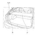
- FIG. 3 is a partial perspective view of a luggage room at the rear of the vehicle corresponding to FIG. 2 and showing a tonneau cover in an open state.
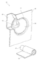
- FIG. 6 is an exploded perspective view corresponding to FIG. 5 and viewed from the back side.
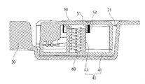
- FIG. 2 is a cross-sectional view taken along line AA in FIG. FIG.
- FIG. 3 is a sectional view taken along line BB in FIG. 1.
- 5 corresponds to FIG. 4 and is a partial perspective view for explaining a locked state of the lock member.
- FIG. FIG. 6 is a cross-sectional view corresponding to FIG. 1 for explaining a locked state of the lock member.
- reference numeral 10 denotes a tonneau cover locking mechanism.
- the tonneau cover 20 that covers the upper portion of the luggage room at the rear of the vehicle so as to be opened and closed is closed (see FIG. 2). It is for locking to.
- the tonneau cover 20 is not shown, the base end side thereof is taken up by the take-up mechanism, and is always shortened by the entraining biasing force as shown in FIG. 3, and is shown in FIG. 2 against the entraining biasing force.
- the terminal-side boss 21 By pulling out the terminal-side boss 21, the upper part of the luggage room is covered and opened.
- the tonneau cover locking mechanism 10 includes the following parts. The following (1) to (5) will be described later.
- (1) Recess 31 (2) Base member 40 (3) Lock member 50 (4) Spring 60 (5) Damper 70
- the parts of the tonneau cover locking mechanism 10 are not limited to the above (1) to (5).
- the recess 31 As shown in FIGS. 1 and 5, the recess 31 is for receiving a lock member 50 described later, and for holding the lock member 50 rotatably.
- the recess 31 is provided in the vehicle interior panel 30 as shown in FIGS.
- the recess 31 is provided directly on the vehicle interior panel 30, but is not limited thereto, and may be provided separately from the vehicle interior panel 30 and fixed to the vehicle interior panel 30.
- the concave portion 31 is recessed in a substantially circular shape from the surface of the vehicle interior panel 30, and has a flat circular bottom portion, a peripheral wall surrounding the bottom portion in a cylindrical shape, and a surface facing the bottom portion being opened in a circular shape.
- a guide groove 32 through which the terminal-side boss 21 of the tonneau cover 20 can pass is provided in a part of the peripheral wall of the recess 31.
- the bottom of the guide groove 32 is formed substantially flush with the bottom of the recess 31 and is opened at a predetermined angle, for example, an angle of about 60 degrees with respect to the center of the flat circular bottom. Further, the guide groove 32 is open in a substantially V-shaped plane toward the outside of the recess 31.
- Base member 40 As shown in FIGS. 1, 5 and 6, the base member 40 is housed in the recess 31 and is used for rotatably supporting a lock member 50 described later.
- the base member 40 is integrally formed of a thermoplastic synthetic resin having appropriate elasticity and rigidity.
- the base member 40 includes the following parts when roughly classified. Each part of the base member 40 is not limited to the following (1) to (5).
- (1) Base body 41 As shown in FIGS. 5 to 8, the base main body 41 is placed on the bottom of the recess 31 and is formed in the same planar circular disk shape as the bottom. The base body 41 is fixed to the bottom of the recess 31 so as not to rotate.
- the shaft portion 42 extends in a cylindrical shape from the center of the base main body 41 and rotatably supports a lock member 50 described later.
- the damper holding portion 43 extends from the base main body 41 in a frame shape and holds a damper 70 described later.
- First restriction section 44 As shown in FIGS. 1 and 5, the first restricting portion 44 abuts on a lock member 50 described later and restricts a receiving position (see FIGS. 1 and 4) described later.
- the first restricting portion 44 is located at one end portion of the damper holding portion 43 and is formed to open in a substantially V shape in a direction away from the side near the shaft portion 42 of the one end portion.
- Second restriction part 45 As shown in FIGS. 5 and 10, the second restricting portion 45 is in contact with a lock member 50 described later and restricts a position (see FIGS. 9 and 10) that will not be reversed, which will be described later.
- the second restricting portion 45 is located at the other end portion of the damper holding portion 43 opposite to the first restricting portion 44, and is substantially V-shaped toward the direction away from the side close to the shaft portion 42 of the other end portion. It is formed to open.
- Lock member 50 As shown in FIGS. 4 to 6, the lock member 50 is formed in a disc shape and is rotatably supported in the recess 31 via the base member 40.
- the lock member 50 is integrally formed of a thermoplastic synthetic resin having appropriate rigidity.
- the lock member 50 is formed in a substantially cup shape with the side facing the base member 40 open, and extends in a cylindrical shape from the periphery of the disc-shaped upper wall toward the base member 40 and faces the base member 40. And a peripheral wall having a circular opening surface. As shown in FIGS. 5 and 6, the lock member 50 includes the following parts when roughly classified. The following (1) to (5) will be described later.
- bearing 51 As shown in FIGS. 1 and 6 to 8, the bearing portion 51 extends in a cylindrical shape from the lower surface of the upper wall of the lock member 50 toward the base member 40, and can rotate on the outer periphery of the shaft portion 42 of the base member 40. It gets stuck.
- Engagement part 52 As shown in FIGS. 1, 4, and 5, the engaging portion 52 is recessed from the periphery of the lock member 50 and can receive the terminal-side boss 21 of the tonneau cover 20.
- the engaging portion 52 has a flat surface recessed in a substantially fan shape or substantially V shape, the bottom surface and the inner surface are closed, and the upper surface and the outer surface on the upper wall side are opened.
- the engaging portion 52 communicates with the opening side surface of the engaging portion 52 and the guide groove 32 at a position corresponding to the guide groove 32 of the recess 31.
- the terminal-side boss 21 inserted through is received, and the position is referred to as an “accepting position”.
- the opening side surface of the engaging portion 52 is blocked by the inner peripheral surface of the peripheral wall of the recess 31. For this reason, if the lock member 50 is rotated in a state where the terminal-side boss 21 is received in the engaging portion 52, the terminal-side boss 21 cannot be removed from the lock member 50.
- the first abutment surface 54 is located in the outer surface of the engaging portion 52, that is, inside the cylindrical peripheral wall, and is inclined in parallel with the first restricting portion 44 that is opened in a substantially V shape. (Second contact surface 55) As shown in FIGS. 6 and 10, the second abutment surface 55 abuts against the second restricting portion 45 of the base member 40 and restricts the “position that does not reverse” (see FIGS. 9 and 10). .
- the second contact surface 55 faces away from the other outer surface of the engaging portion 52, that is, the first contact surface 54, and is positioned inside the cylindrical peripheral wall and is opened in a substantially V shape. Inclined parallel to 45. (Spring 60) The spring 60 urges the first contact surface 54 of the lock member 50 toward the first restricting portion 44 of the base member 40 as shown in FIGS.
- the spring 60 is located in the cylindrical shaft portion 42 of the base member 40, and has one winding end latched on the shaft portion 42 and the other winding end fitted into the outer periphery of the shaft portion 42. Hanging on part 51.
- the first contact surface 54 of the lock member 50 is biased toward the first restricting portion 44 of the base member 40 by the unwinding force of the spring 60.
- the spring 60 is set to have a weak spring force so that the “accepting position” of the lock member 50 does not move due to vehicle vibration or the like.
- the damper 70 brakes the lock member 50 as shown in FIGS.
- As the damper 70 a rotary oil damper using the viscous resistance of silicon oil is used.
- the damper 70 is attached and fixed to the damper holding portion 43 of the base member 40, and meshes the gear 41 with the tooth portion 53 of the lock member 50. (how to use) Next, a method of using the above-described tonneau cover lock mechanism will be described. As shown in FIG. 3, the tonneau cover 20 in the wound state is pulled out as shown in FIG. 2 against the urging force, and the terminal-side boss 21 of the recessed portion 31 is pulled out as shown in FIG. Fit into the guide groove 32.
- the terminal-side boss 21 is fitted inside the opening of the concave engaging portion 52 of the lock member 50 in the “receiving position” (see FIGS. 1 and 4) from the end portion of the guide groove 32. . Thereafter, the terminal-side boss 21 is held and the lock member 50 is rotated toward the “non-inverted position” (see FIGS. 9 and 10).
- the lock member 50 is rotated about 180 degrees, the second abutment surface 55 abuts against the second restricting portion 45 of the base member 40 and is not reversed by the urging urging force of the tonneau cover 20. Stop.
- the tonneau cover 20 is locked in the pulled-out state toward the entraining urging force, and is in a closed state in which the upper part of the luggage room at the rear of the vehicle is covered.
- the terminal-side boss 21 is held and the lock member 50 is rotated toward the “receiving position” (see FIGS. 1 and 4).
- the urging urging force of the tonneau cover 20 acts, and a rotational force that tries to rotate the lock member 50 toward the “accepting position” acts.
Landscapes
- Engineering & Computer Science (AREA)
- Mechanical Engineering (AREA)
- Vehicle Step Arrangements And Article Storage (AREA)
Abstract
トノカバーのロック状態を簡便に且つ迅速に解除することを目的とする。凹部(31)に設けた、円盤状のロック部材(50)に係合部(52)を設け、トノカバーの端末側ボス(21)を受け入れ位置から、トノカバーの巻き込み付勢力により反転しない位置までロック部材(50)の係合部(52)を回転させ、受け入れ位置へは第1の規制部(44)とバネで位置決めされ、反転しない位置へは第2の規制部(45)により位置決めされ、トノカバーの端末側ボス(21)を保持する。係合部(52)は、凹部(31)の内周側に開口を設けたり、凹部は車体内装パネル(30)に設けられたり、ロック部材(50)を制動するダンパー(70)を設けても良い。
Description
この発明は、トノカバーロック機構に関し、ロック解除時に、トノカバーを介して円盤状のロック部材の係合部を回転させることにより、当該ロック状態を簡便に且つ迅速に解除することができるようにしたものである。
従来、トノカバーの端末側に、回転可能なローラを設け、当該ローラをラゲッジルームの上縁に形成したレールに沿って移動可能に構成した車両用トノカバー装置が知られている(特許文献1の段落番号「0014」、並びに図1~3参照)。
上記した従来のレールの途中には、ローラを一時的に停止可能な窪みを設けていた(特許文献1の段落番号「0015」、並びに図3及び図4参照)。
上記した従来のレールの途中には、ローラを一時的に停止可能な窪みを設けていた(特許文献1の段落番号「0015」、並びに図3及び図4参照)。
上記した従来の窪みには、ローラの停止機構を設けていた(特許文献1の段落番号「0016」、並びに図4及び図5参照)。停止機構は、軸に枢支された略L字状の停止部材と、当該停止部材の回動を停止させるフック部材と、当該フック部材によって停止した位置から復帰させるばね部材とから構成されている。
しかし、上記した従来の車両用トノカバー装置では、略L字状の停止部材の回動を停止させるフック部材を必要とし、その構造が複雑であり、又、トノカバーの移動禁止を解除する際に、フック部材を停止部材の爪から外す必要があり(特許文献1の段落番号「0019」、及び図5(B)参照)、フック部材の解除操作が面倒であるという問題点があった。
そこで、本発明は、上記した従来の技術の有する問題点に鑑みてなされたものであり、その目的とするところは、トノカバーのロック状態を簡便に且つ迅速に解除することができるようにしたものである。
本発明は、上記した目的を達成するためになされたものであり、本発明は、次の点を特徴とする。
第1に、トノカバーロック機構は、凹部に設けた、円盤状のロック部材に係合部を設け、トノカバーの端末側ボスを受け入れ位置から、トノカバーの巻き込み付勢力により反転しない位置までロック部材の係合部を回転させるものである。
第2に、受け入れ位置へは第1の規制部とバネで位置決めされる。
第3に、反転しない位置へは第2の規制部により位置決めされ、トノカバーの端末側ボスを保持する。
本発明は、次の点を特徴としてもよい。
第3に、反転しない位置へは第2の規制部により位置決めされ、トノカバーの端末側ボスを保持する。
本発明は、次の点を特徴としてもよい。
すなわち、係合部は、凹部の内周側に開口を設けている。この場合、トノカバーの巻き込み付勢力により反転しない位置において、端末側ボスを強固に保持することができる。
本発明は、次の点を特徴としてもよい。
本発明は、次の点を特徴としてもよい。
すなわち、凹部は、車体内装パネルに設けられている。この場合、部品点数を減少することができる。
本発明は、次の点を特徴としてもよい。
本発明は、次の点を特徴としてもよい。
すなわち、ロック部材を制動するダンパーを設けている。この場合、トノカバーの巻き込み付勢力により反転しない位置からトノカバーの端末側ボスの受け入れ位置に、トノカバーを介して円盤状のロック部材の係合部を回転させる際に特に、ダンパーによる制動力を働かせることができ、その際の質感を向上することができる。
より詳細には、リリース時に手を離してからトノカバーの端末側ボスが円盤状のロック部材から解放されるまでの時間差を設けること、又、反転の負勢がロック・ロック解除操作をアシストすることにより、質感を向上することができる。
より詳細には、リリース時に手を離してからトノカバーの端末側ボスが円盤状のロック部材から解放されるまでの時間差を設けること、又、反転の負勢がロック・ロック解除操作をアシストすることにより、質感を向上することができる。
本発明によれば、トノカバーの巻き込み付勢力により反転しない位置においては第2の規制部により位置決めしているので、当該反転しない位置からトノカバーの端末側ボスの受け入れ位置に、トノカバーを介して円盤状のロック部材の係合部を回転させることにより、トノカバーのロック状態を簡便に且つ迅速に解除することができる。
これに加え、トノカバーの端末側ボスの受け入れ位置においては第1の規制部とバネで位置決めしているので、車両の振動等により、受け入れ位置がずれるのを未然に防止することができる。
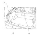
図中、10は、トノカバーロック機構であり、図2及び図3に示すように、車両後部のラゲッジルームの上方を開閉可能に覆うトノカバー20を、当該上方を閉じた閉位置(図2参照)にロックするためのものである。
トノカバー20は、図示しないが、その基端側が巻き取り機構により巻き取られ、常時、巻き込み付勢力により、図3に示すように、短縮し、当該巻き込み付勢力に抗して、図2に示すように、端末側ボス21を引き出すことで、ラゲッジルームの上方を覆い隠すようにして開じる。
トノカバー20は、図示しないが、その基端側が巻き取り機構により巻き取られ、常時、巻き込み付勢力により、図3に示すように、短縮し、当該巻き込み付勢力に抗して、図2に示すように、端末側ボス21を引き出すことで、ラゲッジルームの上方を覆い隠すようにして開じる。
トノカバーロック機構10は、図5及び図6に示すように、大別すると、次のパーツを備える。
なお、次の(1)~(5)については、後述する。
(1)凹部31
(2)ベース部材40
(3)ロック部材50
(4)バネ60
(5)ダンパー70
なお、トノカバーロック機構10のパーツは、上記した(1)~(5)に限定されない。
(凹部31)
凹部31は、図1及び図5に示すように、後述するロック部材50がはまり込むものであり、当該ロック部材50を回転可能に保持するためのものである。
なお、次の(1)~(5)については、後述する。
(1)凹部31
(2)ベース部材40
(3)ロック部材50
(4)バネ60
(5)ダンパー70
なお、トノカバーロック機構10のパーツは、上記した(1)~(5)に限定されない。
(凹部31)
凹部31は、図1及び図5に示すように、後述するロック部材50がはまり込むものであり、当該ロック部材50を回転可能に保持するためのものである。
凹部31は、図1~4に示すように、車体内装パネル30に設けられている。
なお、凹部31を、車体内装パネル30に直接、設けたが、これに限定されず、車体内装パネル30と別体に設け、車体内装パネル30に固定するようにしても良い。
凹部31は、車体内装パネル30の表面から略円形に凹み、平面円形の底部と、当該底部の周囲を円筒形に囲み、底部と対向する面が円形に開放した周壁とを有する。
なお、凹部31を、車体内装パネル30に直接、設けたが、これに限定されず、車体内装パネル30と別体に設け、車体内装パネル30に固定するようにしても良い。
凹部31は、車体内装パネル30の表面から略円形に凹み、平面円形の底部と、当該底部の周囲を円筒形に囲み、底部と対向する面が円形に開放した周壁とを有する。
凹部31の周壁の一部には、トノカバー20の端末側ボス21が通過可能なガイド溝32を設けている。ガイド溝32は、その底を凹部31の底部と略面一に形成し、当該平面円形の底部の中心に対して所定の角度、例えば約60度の角度で開口させている。また、ガイド溝32は、凹部31の外側に向かって平面略V字形に開いている。
(ベース部材40)
ベース部材40は、図1、図5及び図6に示すように、凹部31内に収納され、後述するロック部材50が回転可能に支持するためのものである。ベース部材40は、適度な弾性と剛性とを有する熱可塑性合成樹脂により一体的に形成されている。
(ベース部材40)
ベース部材40は、図1、図5及び図6に示すように、凹部31内に収納され、後述するロック部材50が回転可能に支持するためのものである。ベース部材40は、適度な弾性と剛性とを有する熱可塑性合成樹脂により一体的に形成されている。
ベース部材40は、図5に示すように、大別すると、次の各部を備える。
なお、ベース部材40の各部は、次の(1)~(5)に限定されない。
(1)ベース本体41
ベース本体41は、図5~8に示すように、凹部31の底部に載置されるものであり、当該底部と同一の平面円形の円盤状に形成されている。ベース本体41は、凹部31の底部に回転不能に固定される。
なお、ベース部材40の各部は、次の(1)~(5)に限定されない。
(1)ベース本体41
ベース本体41は、図5~8に示すように、凹部31の底部に載置されるものであり、当該底部と同一の平面円形の円盤状に形成されている。ベース本体41は、凹部31の底部に回転不能に固定される。
(2)軸部42
軸部42は、図5、図7及び図8に示すように、ベース本体41の中心から円筒形に延び、後述するロック部材50を回転可能に支持するためのものである。
(3)ダンパー保持部43
ダンパー保持部43は、図1及び図5に示すように、ベース本体41から枠状に延び、後述するダンパー70を保持するためのものである。
軸部42は、図5、図7及び図8に示すように、ベース本体41の中心から円筒形に延び、後述するロック部材50を回転可能に支持するためのものである。
(3)ダンパー保持部43
ダンパー保持部43は、図1及び図5に示すように、ベース本体41から枠状に延び、後述するダンパー70を保持するためのものである。
(4)第1規制部44
第1規制部44は、図1及び図5に示すように、後述するロック部材50と当接し、同じく後述する受け入れ位置(図1及び図4参照)を規制するものである。
第1規制部44は、ダンパー保持部43の一端部に位置し、当該一端部の軸部42に近い側から離隔する方向に向かって略V字形に開くように形成されている。
第1規制部44は、図1及び図5に示すように、後述するロック部材50と当接し、同じく後述する受け入れ位置(図1及び図4参照)を規制するものである。
第1規制部44は、ダンパー保持部43の一端部に位置し、当該一端部の軸部42に近い側から離隔する方向に向かって略V字形に開くように形成されている。
(5)第2規制部45
第2規制部45は、図5及び図10に示すように、後述するロック部材50と当接し、同じく後述する反転しない位置(図9及び図10参照)を規制するものである。第2規制部45は、第1規制部44と反対側のダンパー保持部43の他端部に位置し、当該他端部の軸部42に近い側から離隔する方向に向かって略V字形に開くように形成されている。
(ロック部材50)
ロック部材50は、図4~6に示すように、円盤状に形成され、ベース部材40を介して、凹部31内に回転可能に支持される。ロック部材50は、適度な剛性を有する熱可塑性合成樹脂により一体的に形成されている。
第2規制部45は、図5及び図10に示すように、後述するロック部材50と当接し、同じく後述する反転しない位置(図9及び図10参照)を規制するものである。第2規制部45は、第1規制部44と反対側のダンパー保持部43の他端部に位置し、当該他端部の軸部42に近い側から離隔する方向に向かって略V字形に開くように形成されている。
(ロック部材50)
ロック部材50は、図4~6に示すように、円盤状に形成され、ベース部材40を介して、凹部31内に回転可能に支持される。ロック部材50は、適度な剛性を有する熱可塑性合成樹脂により一体的に形成されている。
ロック部材50は、ベース部材40と対向する側が開放した略コップ形に形成され、円盤形の上壁と、当該上壁の周囲からベース部材40に向かって円筒形に延び、ベース部材40と対向する面が円形に開放した周壁とを有する。
ロック部材50は、図5及び図6に示すように、大別すると、次の各部を備える。
なお、次の(1)~(5)については後述する。
ロック部材50は、図5及び図6に示すように、大別すると、次の各部を備える。
なお、次の(1)~(5)については後述する。
(1)軸受部51
(2)係合部52
(3)歯部53
(4)第1当接面54
(5)第2当接面55
なお、ロック部材50の各部は、次の(1)~(5)に限定されない。
(軸受部51)
軸受部51は、図1及び図6~8に示すように、ロック部材50の上壁の下面からベース部材40に向かって円筒形に延び、当該ベース部材40の軸部42の外周に回転可能にはまり込むものである。
(係合部52)
係合部52は、図1、図4及び図5に示すように、ロック部材50の周囲から凹み、トノカバー20の端末側ボス21を受け入れ可能なものである。係合部52は、平面が略扇形ないしは略V字形に凹み、底面及び内側面が塞がれ、上壁側の上面及び外側面が開口する。
(2)係合部52
(3)歯部53
(4)第1当接面54
(5)第2当接面55
なお、ロック部材50の各部は、次の(1)~(5)に限定されない。
(軸受部51)
軸受部51は、図1及び図6~8に示すように、ロック部材50の上壁の下面からベース部材40に向かって円筒形に延び、当該ベース部材40の軸部42の外周に回転可能にはまり込むものである。
(係合部52)
係合部52は、図1、図4及び図5に示すように、ロック部材50の周囲から凹み、トノカバー20の端末側ボス21を受け入れ可能なものである。係合部52は、平面が略扇形ないしは略V字形に凹み、底面及び内側面が塞がれ、上壁側の上面及び外側面が開口する。
係合部52は、図1及び図4に示すように、凹部31のガイド溝32と一致させた位置で、係合部52の開口側面とガイド溝32とが相互に連通し、ガイド溝32を通して差し込まれた端末側ボス21を受け入れ、当該位置を「受け入れ位置」という。
「受け入れ位置」から、ロック部材50を回転させると、係合部52の開口側面が、凹部31の周壁の内周面により塞がれる。このため、係合部52に端末側ボス21を受け入れた状態で、ロック部材50を回転させると、端末側ボス21がロック部材50から抜けなくなる。
「受け入れ位置」から、ロック部材50を回転させると、係合部52の開口側面が、凹部31の周壁の内周面により塞がれる。このため、係合部52に端末側ボス21を受け入れた状態で、ロック部材50を回転させると、端末側ボス21がロック部材50から抜けなくなる。
その後、図9及び図10に示すように、ロック部材50を所定の角度、例えば「受け入れ位置」から約180度回転した位置においては、トノカバー20の巻き込み付勢力により反転しなくなり、当該位置を「反転しない位置」という。
(歯部53)
歯部53は、図1、図6及び図8に示すように、歯部53の外周に形成され、後述するダンパー70の歯車71とかみ合うものである。
(第1当接面54)
第1当接面54は、図1及び図6に示すように、ベース部材40の第1規制部44と当接し、「受け入れ位置」(図1及び図4参照)を規制するものである。
(歯部53)
歯部53は、図1、図6及び図8に示すように、歯部53の外周に形成され、後述するダンパー70の歯車71とかみ合うものである。
(第1当接面54)
第1当接面54は、図1及び図6に示すように、ベース部材40の第1規制部44と当接し、「受け入れ位置」(図1及び図4参照)を規制するものである。
第1当接面54は、係合部52の外側面、すなわち円筒形の周壁の内部に位置し、略V字形に開いた第1規制部44と平行に傾斜させている。
(第2当接面55)
第2当接面55は、図6及び図10に示すように、ベース部材40の第2規制部45と当接し、「反転しない位置」(図9及び図10参照)を規制するものである。
(第2当接面55)
第2当接面55は、図6及び図10に示すように、ベース部材40の第2規制部45と当接し、「反転しない位置」(図9及び図10参照)を規制するものである。
第2当接面55は、係合部52の他方の外側面、すなわち第1当接面54と背向し、円筒形の周壁の内部に位置し、略V字形に開いた第2規制部45と平行に傾斜させている。
(バネ60)
バネ60は、図5~8に示すように、ベース部材40の第1規制部44に向かって、ロック部材50の第1当接面54を付勢するものである。
(バネ60)
バネ60は、図5~8に示すように、ベース部材40の第1規制部44に向かって、ロック部材50の第1当接面54を付勢するものである。
バネ60は、ベース部材40の円筒形の軸部42内に位置し、その一方の巻き端を軸部42に掛け止め、他方の巻き端を軸部42の外周にはまり込むロック部材50の軸受部51に掛け止める。バネ60が巻き解く力により、ロック部材50の第1当接面54をベース部材40の第1規制部44に向かって付勢している。バネ60は、バネ力が弱く設定され、車両の振動等により、ロック部材50が「受け入れ位置」が移動しないようにするためのものである。
(ダンパー70)
ダンパー70は、図1、図5及び図6に示すように、ロック部材50を制動するものである。ダンパー70は、シリコンオイルの粘性抵抗を利用した回転式のオイルダンパーが使用されている。
(ダンパー70)
ダンパー70は、図1、図5及び図6に示すように、ロック部材50を制動するものである。ダンパー70は、シリコンオイルの粘性抵抗を利用した回転式のオイルダンパーが使用されている。
ダンパー70は、図1及び図8に示すように、ベース部材40のダンパー保持部43に装着されて固定され、その歯車41をロック部材50の歯部53とかみ合わせている。
(使用方法)
つぎに、上記したトノカバーロック機構の使用方法について説明する。
図3に示すように、巻き取られた状態のトノカバー20を、巻き込み付勢力に抗して、図2に示すように、引き出し、図4に示すように、その端末側ボス21を凹部31のガイド溝32に合わせてはめ込む。
(使用方法)
つぎに、上記したトノカバーロック機構の使用方法について説明する。
図3に示すように、巻き取られた状態のトノカバー20を、巻き込み付勢力に抗して、図2に示すように、引き出し、図4に示すように、その端末側ボス21を凹部31のガイド溝32に合わせてはめ込む。
端末側ボス21は、ガイド溝32の終端部から、図4に示すように、「受け入れ位置」(図1及び図4参照)のロック部材50の凹状の係合部52の開口から内部にはめ込む。
その後、端末側ボス21を持って、ロック部材50を「反転しない位置」(図9及び図10参照)に向かって回転させる。
ロック部材50を約180度回転させると、その第2当接面55がベース部材40の第2規制部45に当接し、トノカバー20の巻き込み付勢力により反転しなくなり、当該「反転しない位置」に停止する。
その後、端末側ボス21を持って、ロック部材50を「反転しない位置」(図9及び図10参照)に向かって回転させる。
ロック部材50を約180度回転させると、その第2当接面55がベース部材40の第2規制部45に当接し、トノカバー20の巻き込み付勢力により反転しなくなり、当該「反転しない位置」に停止する。
トノカバー20は、その巻き込み付勢力に向して、引き出された状態にロックされ、車両後部のラゲッジルームの上方が覆われた閉じた状態なる。
一方、ロック状態を解除するには、端末側ボス21を持って、ロック部材50を「受け入れ位置」(図1及び図4参照)に向かって回転させれば良い。
このとき、トノカバー20の巻き込み付勢力が作用し、ロック部材50を「受け入れ位置」に向かって回転しようとする回転力が働く。
一方、ロック状態を解除するには、端末側ボス21を持って、ロック部材50を「受け入れ位置」(図1及び図4参照)に向かって回転させれば良い。
このとき、トノカバー20の巻き込み付勢力が作用し、ロック部材50を「受け入れ位置」に向かって回転しようとする回転力が働く。
その際に、ロック部材50の歯部53と、ダンパー70の歯車41とのかみ合いにより、歯車41が回転し、ダンパー70の制動力が働く。
このため、ロック部材50は、「受け入れ位置」(図1及び図4参照)に向かってゆっくりと且つ静粛に回転する。
ロック部材50が「受け入れ位置」まで回転すると、その第1当接面54がベース部材40の第1規制部44と当接し、ロック部材50の回転が停止する。
このため、ロック部材50は、「受け入れ位置」(図1及び図4参照)に向かってゆっくりと且つ静粛に回転する。
ロック部材50が「受け入れ位置」まで回転すると、その第1当接面54がベース部材40の第1規制部44と当接し、ロック部材50の回転が停止する。
「受け入れ位置」において、ロック部材50の係合部52の開口が、凹部31のガイド溝32と一致し、開放される。
このため、端末側ボス21を、係合部52からガイド溝32を通して抜き取ることで、ロック状態が解除され、トノカバー20を開放させることができる。
2011年3月22日に出願された日本特許出願第2011-062353号の明細書、特許請求の範囲、図面及び要約書の全内容をここに引用し、本発明の明細書の開示として、取り入れるものである。
このため、端末側ボス21を、係合部52からガイド溝32を通して抜き取ることで、ロック状態が解除され、トノカバー20を開放させることができる。
2011年3月22日に出願された日本特許出願第2011-062353号の明細書、特許請求の範囲、図面及び要約書の全内容をここに引用し、本発明の明細書の開示として、取り入れるものである。
Claims (4)
- 凹部に設けた、円盤状のロック部材に係合部を設け、トノカバーの端末側ボスを受け入れ位置から、前記トノカバーの巻き込み付勢力により反転しない位置まで前記ロック部材の前記係合部を回転させ、
前記受け入れ位置へは第1の規制部とバネで位置決めされ、
前記反転しない位置へは第2の規制部により位置決めされ、
前記トノカバーの前記端末側ボスを保持することを特徴とした、トノカバーロック機構。 - 請求項1に記載のトノカバーロック機構であって、
前記係合部は、
前記凹部の内周側に開口を設けていることを特徴とした、トノカバーロック機構。 - 請求項1又は請求項2に記載のトノカバーロック機構であって、
前記凹部は、
車体内装パネルに設けられていることを特徴とした、トノカバーロック機構。 - 請求項1~3のいずれか1項に記載のトノカバーロック機構であって、
前記ロック部材を制動するダンパーを設けていることを特徴とした、トノカバーロック機構。
Applications Claiming Priority (2)
| Application Number | Priority Date | Filing Date | Title |
|---|---|---|---|
| JP2011062353A JP5694820B2 (ja) | 2011-03-22 | 2011-03-22 | トノカバーロック機構 |
| JP2011-062353 | 2011-03-22 |
Publications (1)
| Publication Number | Publication Date |
|---|---|
| WO2012128157A1 true WO2012128157A1 (ja) | 2012-09-27 |
Family
ID=46879308
Family Applications (1)
| Application Number | Title | Priority Date | Filing Date |
|---|---|---|---|
| PCT/JP2012/056603 Ceased WO2012128157A1 (ja) | 2011-03-22 | 2012-03-14 | トノカバーロック機構 |
Country Status (2)
| Country | Link |
|---|---|
| JP (1) | JP5694820B2 (ja) |
| WO (1) | WO2012128157A1 (ja) |
Cited By (3)
| Publication number | Priority date | Publication date | Assignee | Title |
|---|---|---|---|---|
| EP2875997A1 (fr) * | 2013-11-26 | 2015-05-27 | Centre D'etude Et De Recherche Pour L'automobile (Cera) | Système de recouvrement d'un compartiment à bagages de véhicule automobile |
| EP2875998A1 (fr) * | 2013-11-26 | 2015-05-27 | Centre D'etude Et De Recherche Pour L'automobile (Cera) | Dispositif de recouvrement d'un compartiment à bagages de véhicule automobile |
| FR3017348A1 (fr) * | 2014-02-07 | 2015-08-14 | Ct D Etude Et De Rech Automobile Cera | Dispositif de recouvrement d'un compartiment a bagages de vehicule automobile |
Citations (3)
| Publication number | Priority date | Publication date | Assignee | Title |
|---|---|---|---|---|
| JPS60174343A (ja) * | 1984-02-17 | 1985-09-07 | Nissan Motor Co Ltd | 自動車用トノカバ− |
| JPH09109776A (ja) * | 1995-10-13 | 1997-04-28 | Kasai Kogyo Co Ltd | 車両用トノカバー装置 |
| JP2000318529A (ja) * | 1999-05-13 | 2000-11-21 | Kanto Auto Works Ltd | 自動車のトノカバー |
-
2011
- 2011-03-22 JP JP2011062353A patent/JP5694820B2/ja not_active Expired - Fee Related
-
2012
- 2012-03-14 WO PCT/JP2012/056603 patent/WO2012128157A1/ja not_active Ceased
Patent Citations (3)
| Publication number | Priority date | Publication date | Assignee | Title |
|---|---|---|---|---|
| JPS60174343A (ja) * | 1984-02-17 | 1985-09-07 | Nissan Motor Co Ltd | 自動車用トノカバ− |
| JPH09109776A (ja) * | 1995-10-13 | 1997-04-28 | Kasai Kogyo Co Ltd | 車両用トノカバー装置 |
| JP2000318529A (ja) * | 1999-05-13 | 2000-11-21 | Kanto Auto Works Ltd | 自動車のトノカバー |
Cited By (6)
| Publication number | Priority date | Publication date | Assignee | Title |
|---|---|---|---|---|
| EP2875997A1 (fr) * | 2013-11-26 | 2015-05-27 | Centre D'etude Et De Recherche Pour L'automobile (Cera) | Système de recouvrement d'un compartiment à bagages de véhicule automobile |
| EP2875998A1 (fr) * | 2013-11-26 | 2015-05-27 | Centre D'etude Et De Recherche Pour L'automobile (Cera) | Dispositif de recouvrement d'un compartiment à bagages de véhicule automobile |
| FR3013649A1 (fr) * | 2013-11-26 | 2015-05-29 | Cera | Systeme de recouvrement d’un compartiment a bagages de vehicule automobile |
| FR3013650A1 (fr) * | 2013-11-26 | 2015-05-29 | Cera | Dispositif de recouvrement d'un compartiment a bagages de vehicule automobile |
| CN104670101A (zh) * | 2013-11-26 | 2015-06-03 | 汽车研究中心 | 用于遮盖机动车辆行李厢的系统 |
| FR3017348A1 (fr) * | 2014-02-07 | 2015-08-14 | Ct D Etude Et De Rech Automobile Cera | Dispositif de recouvrement d'un compartiment a bagages de vehicule automobile |
Also Published As
| Publication number | Publication date |
|---|---|
| JP2012197027A (ja) | 2012-10-18 |
| JP5694820B2 (ja) | 2015-04-01 |
Similar Documents
| Publication | Publication Date | Title |
|---|---|---|
| US8186638B2 (en) | Apparatus with a rotating body | |
| JP6321537B2 (ja) | 塗膜転写具 | |
| JPH04219532A (ja) | 両方向係止クラッチ | |
| JP5694820B2 (ja) | トノカバーロック機構 | |
| JP5890185B2 (ja) | 車両用コンソールボックス | |
| JPWO2011016093A1 (ja) | 車載用表示装置 | |
| JP6590965B2 (ja) | ベルトリトラクター用のロック機構 | |
| JP5976129B2 (ja) | ベルトシャフトの巻き取り方向でガタつき防止効果を有する自動ロックベルトリトラクタ | |
| JP2005212899A (ja) | 収納ボックス | |
| JP2004217367A (ja) | シート状物の巻き取り機構 | |
| JP2016222109A (ja) | ウェビング巻取装置 | |
| JP5075164B2 (ja) | 上吊り引戸の閉扉機能付き戸車装置 | |
| JP3890340B2 (ja) | 引き戸閉鎖装置 | |
| JP5311651B2 (ja) | シャッター用ロック装置及びシャッター装置 | |
| JP3625956B2 (ja) | ロールカーテン | |
| JP6523001B2 (ja) | シートベルトリトラクタ | |
| JP4210144B2 (ja) | 車両用収納装置 | |
| JP6941558B2 (ja) | 両軸受リール | |
| JP3934486B2 (ja) | 線引き具 | |
| JP5040840B2 (ja) | 制動装置 | |
| JP3818953B2 (ja) | シート巻取り装置 | |
| JP5010568B2 (ja) | 車両用ゴミ箱 | |
| US1325401A (en) | Curtain-adjuster | |
| JP4138113B2 (ja) | 窓開閉操作装置 | |
| JP2018091106A (ja) | 遮蔽装置 |
Legal Events
| Date | Code | Title | Description |
|---|---|---|---|
| 121 | Ep: the epo has been informed by wipo that ep was designated in this application |
Ref document number: 12760998 Country of ref document: EP Kind code of ref document: A1 |
|
| NENP | Non-entry into the national phase |
Ref country code: DE |
|
| 122 | Ep: pct application non-entry in european phase |
Ref document number: 12760998 Country of ref document: EP Kind code of ref document: A1 |