WO2012127557A1 - 口付け装置及び口付け方法 - Google Patents
口付け装置及び口付け方法 Download PDFInfo
- Publication number
- WO2012127557A1 WO2012127557A1 PCT/JP2011/056540 JP2011056540W WO2012127557A1 WO 2012127557 A1 WO2012127557 A1 WO 2012127557A1 JP 2011056540 W JP2011056540 W JP 2011056540W WO 2012127557 A1 WO2012127557 A1 WO 2012127557A1
- Authority
- WO
- WIPO (PCT)
- Prior art keywords
- metal tube
- axis
- diameter
- parallel
- tip portion
- Prior art date
- Legal status (The legal status is an assumption and is not a legal conclusion. Google has not performed a legal analysis and makes no representation as to the accuracy of the status listed.)
- Ceased
Links
Images



Classifications
-
- B—PERFORMING OPERATIONS; TRANSPORTING
- B21—MECHANICAL METAL-WORKING WITHOUT ESSENTIALLY REMOVING MATERIAL; PUNCHING METAL
- B21C—MANUFACTURE OF METAL SHEETS, WIRE, RODS, TUBES, PROFILES OR LIKE SEMI-MANUFACTURED PRODUCTS OTHERWISE THAN BY ROLLING; AUXILIARY OPERATIONS USED IN CONNECTION WITH METAL-WORKING WITHOUT ESSENTIALLY REMOVING MATERIAL
- B21C5/00—Pointing; Push-pointing
- B21C5/003—Pointing; Push-pointing of hollow material, e.g. tube
-
- B—PERFORMING OPERATIONS; TRANSPORTING
- B21—MECHANICAL METAL-WORKING WITHOUT ESSENTIALLY REMOVING MATERIAL; PUNCHING METAL
- B21C—MANUFACTURE OF METAL SHEETS, WIRE, RODS, TUBES, PROFILES OR LIKE SEMI-MANUFACTURED PRODUCTS OTHERWISE THAN BY ROLLING; AUXILIARY OPERATIONS USED IN CONNECTION WITH METAL-WORKING WITHOUT ESSENTIALLY REMOVING MATERIAL
- B21C5/00—Pointing; Push-pointing
- B21C5/006—Pointing; Push-pointing of solid material, e.g. wire or profiles
Definitions
- the present invention relates to a metal pipe splicing device and a metal pipe splicing method using the splicing device, and more particularly to a cold drawn steel pipe splicing device and a splicing method.
- a die drawing method is generally used as a method of drawing a metal pipe such as a cold drawn steel pipe.
- a metal pipe such as a cold drawn steel pipe.
- This method of forming the mouthpiece is generally referred to as a “mouthing method”.
- one end portion of a cylindrical metal tube such as a cold drawn steel tube is processed to have an outer diameter smaller than the outer diameter of a non-processed portion other than the tip portion.
- a method is known in which the tip portion is processed into a cylindrical shape having an outer diameter smaller than that of the non-processed portion by, for example, swaging.
- a method is also known in which the tip portion is struck by a press or a hammer to form a flat plate, and then bent so as to be thinner than the outer diameter of the non-processed portion (see, for example, Non-Patent Document 1). .
- the tip portion of the metal tube having an outer diameter smaller than the outer diameter of the non-processed portion by such processing is generally referred to as a “mouth portion”.
- a mouth portion By forming the narrow mouth portion in this way, the tip portion of the metal tube can be inserted into the die hole. After inserting the mouthpiece from one side of the die hole, the metal tube is drawn out by pulling out the metal tube from the other side of the die hole at a constant speed.
- the mouthpiece needs to be processed into a shape suitable for insertion into a die hole.
- the mouthpiece needs to have an outer shape parallel to the axial direction of the metal tube, and the outer diameter needs to be smaller than the inner diameter of the die hole.
- the intermediate portion having a tapered truncated cone shape is formed from the raw portion of the metal tube to the mouthed portion. It is formed.
- the plug does not reach directly under the die at the start of drawing.
- the non-processed part becomes long, and there is a problem that the product yield decreases.
- An object of the present invention is to provide a mouth attaching device and a mouth attaching method.
- a splicing device is a device that forms a splicing portion at a tip portion of a metal tube before being stretched, and is annularly arranged around an axis and coaxial with a coaxial line.
- a plurality of split molds that receive the tip portion to be inserted, and a pressurizing mechanism that causes the split molds to approach and separate from the tip portion;
- the parallel pressure surface parallel to the axis line and the edge of the parallel pressure surface on the back side in the insertion direction of the metal tube are continuous.
- an enlarged pressure surface that expands in a direction away from the end edge, and an end edge of the parallel pressure surface on the front side in the insertion direction of the metal tube with respect to each divided mold.
- the pressurizing mechanism includes a pressurizing unit in which each of the divided molds is fitted, and the axial direction between the pressurizing unit and each of the split molds. And a drive unit that approaches and separates from each other along the direction; the shape of the mating surface between the pressurizing unit and each of the divided molds when viewed in a cross-section including the axis is the back side in the insertion direction
- the taper shape increases in diameter toward the surface; the configuration may be adopted.
- the drive unit guides the divided molds in a direction in which the divided molds are moved toward and away from the tip portion, and the divided molds. And a biasing member that biases in a direction away from the tip portion.
- chamfering may be formed on an edge of the parallel pressure surface on the near side in the insertion direction.
- the length dimension of the parallel pressure surface may be longer than the length dimension of the enlarged pressure surface. Good.
- the splicing device further includes a rotation mechanism that rotates the metal tube having the tip portion inserted into each of the divided molds and in a non-pressurized state around the axis. You may prepare.
- an angle formed by the locking surface with respect to the axis is the axis.
- it may be larger than the angle formed by the diameter-enlarged pressure surface.
- the angle formed by the locking surface with respect to the axis may be 90 degrees.
- the splicing method is a method of forming a splicing portion at a tip portion of a metal tube before being stretched, and is an outer peripheral surface at an intermediate position in the axial direction of the tip portion. Pressing a parallel pressure surface parallel to the axis and pressurizing, and pressing and pressing a diameter-enlarged pressure surface that expands toward the tip side from the middle position. A first pressurizing step for simultaneously locking the rear end side of the midway position; and after the first pressurizing step, pressurization is performed on the diameter-enlarged pressurizing surface of the tip portion. A second pressurizing step of pressing the parallel pressurizing surface against the tip side of the portion and pressurizing again.
- the splicing method according to the above (9) includes a rotating step of rotating the metal tube by a predetermined angle around the axis during the first pressurizing step or the second pressurizing step. Further, it may be provided.
- the tip end portion is made parallel to the parallel pressurizing surface and the enlarged surface.
- the diameter can be reduced by applying pressure on the diameter pressing surface.
- the portion pressed by the parallel pressing surface is reduced in diameter so as to have a uniform outer diameter along the axial direction of the metal tube.
- the portion of the tip portion that is pressed by the expanded pressure surface is reduced in diameter to a shape that matches the shape of the expanded pressure surface. While deforming. This reaction force acts to urge the tip portion toward the back side in the insertion direction.
- the metal tube is not displaced along the axial direction. Subsequently, the portion reduced in diameter to the above-mentioned diameter-enlarged shape is pressed again by the parallel pressing surface, so that a mouthpiece having a uniform outer diameter along the axial direction can be formed. According to this device, the mouthpiece can be formed without using conventional hitting. Therefore, the tapered truncated cone connecting the unprocessed part of the metal tube and the mouthed part can be greatly shortened or omitted at all, and it can be applied to multiple metal tubes.
- both the length dimension of the mouthpiece portion and the length dimension of the other portion can always be made constant. Therefore, when forming the mouthpiece in the metal tube, it is possible to improve the yield regarding the mouthpiece and other length dimensions after eliminating the noise problem.
- each outer peripheral surface of each divided mold slides on the mating surface with the pressurizing part by reciprocating each divided mold in the axial direction.
- the inner diameter dimension of the opening formed in each divided mold can be reduced or enlarged, so that the tip portion of the metal tube can be pressurized or released.
- the stroke of this reciprocating movement the lip portion can be machined to an arbitrary outer diameter, so labor and time loss associated with die replacement can be reduced, and costs can be reduced by reducing die types. It becomes.
- each of the divided molds after pressurizing the distal end portion of the metal tube is subjected to the distal end portion by the biasing force of the biasing member while being guided by the guide member. Can be separated automatically and reliably. For this reason, it is possible to perform the kissing process more smoothly.
- the splicing device since the chamfer is formed on the front edge of the parallel pressure surface, the tip of the metal tube when the metal tube is pressurized with the parallel pressure surface. It is possible to suppress the occurrence of excessive swell at the boundary between the part and the other part. As a result, at the start of the drawing process of the metal tube, the raised part is detached from the metal tube and is sandwiched between the dies (division mold) and the metal tube, and the metal tube is drawn on the outer peripheral surface in the subsequent drawing process of the metal tube. Generation of streak-like scratches parallel to the axis can be prevented.
- the mouthpiece portion has a uniform outer diameter dimension over the entire length in the axial direction. It can be pressure molded to have.
- the present mouth attaching device can be applied even when processing a metal tube having a large rise in meat or when the amount of drawing of the outer shape of the metal tube by pressurization is large.
- the diameter-enlarged pressure surface is more than the thrust force that tries to push the tip portion toward the back in the insertion direction.
- the force by which the locking surface prevents the tip portion from moving is stronger. Therefore, it is possible to reliably prevent displacement of the metal tube including the tip portion in the axial direction.
- the tip portion in the first pressurizing step, can be pressed by the parallel pressurizing surface and the diameter-enlarging pressurizing surface to reduce the diameter.
- the portion pressed by the parallel pressing surface of the tip portion is reduced in diameter so as to have a uniform outer diameter along the axial direction of the metal tube.
- the portion of the tip portion that is pressed by the expanded pressure surface is reduced in diameter to a shape that matches the shape of the expanded pressure surface. While deforming. This reaction force acts to urge the tip portion toward the tip side.
- the metal tube since the rear end side of the midway position of the front end portion is locked, the metal tube is not displaced along the axial direction.
- the mouthpiece having a uniform outer diameter dimension along the axial direction can be formed. Therefore, even if the mouthpiece is formed on a plurality of metal tubes, both the length dimension of the mouthpiece and the length dimension of the other parts can always be made constant. In addition, the mouthpiece can be formed without using conventional hitting. Therefore, when forming the mouthpiece in the metal tube, it is possible to improve the yield regarding the mouthpiece and other length dimensions after eliminating the noise problem.
- the gap between the adjacent divided molds is provided during the first pressurization process or the second pressurization process. Even if the metal pipe is bulged, the bulge of the meat can be pressed and crushed by once stopping the pressurization and rotating the metal pipe and then restarting the pressurization. In particular, when the thickness of the metal tube is thin, or when the amount of reduction in the outer diameter of the metal tube due to pressurization is large, the above-mentioned bulge of the meat is sandwiched between the joint surfaces of the adjacent split molds and pressurizes. There is an effect that prevents the process from being continued.
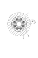
- FIG. 2 is a cross-sectional view of the mouth attaching device when viewed along line AA in FIG. 1.
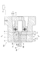
- FIG. 2 is a cross-sectional view of the mouth attaching device when viewed along line BB in FIG. 1.
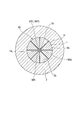
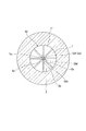
- FIG. 5 is a cross-sectional view of the mouthpiece when viewed along line CC in FIG. 4.
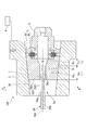
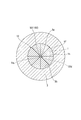
- FIG. 7 is a cross-sectional view of the mouth attaching device when viewed along line DD in FIG. 6. It is a figure showing the next process of the same attachment method, Comprising: It is sectional drawing in the same cross section as FIG. It is sectional drawing at the time of seeing the same mouth attaching apparatus in the EE line of FIG.
- the mouthpiece device 100 of the present embodiment is a device that forms a mouthpiece at the tip of a metal tube 50, and includes a mold 10, a pressurizing mechanism 20, and a rotating mechanism 6. It is schematically configured. Details of each component will be described below. In the following description, when forming the fitting portion, the back side (end edge 50c) side of the distal end portion 50f of the metal tube 50 is one side, and the front side in the insertion direction of the metal tube 50 is the other side. .
- the mold 10 is for pressurizing the outer peripheral surface 50 i of the tip portion 50 f of the metal tube 50. As shown in FIG. 1, the mold 10 is embedded in the pressure unit 2.
- the mold 10 is composed of a plurality of divided molds 1 and is annularly arranged around the axis 50 d of the metal tube 50.
- the mold 10 has a shape in which the truncated cone is divided into a plurality of divided molds 1 by dividing the truncated cone into a plurality of cross sections including its axis (in this embodiment, eight divisions).
- the other side (parallel pressure surface 1a 2 ) of the inner peripheral surfaces of each divided mold 1 abuts on the outer peripheral surface 50i of the metal tube 50 so that the metal tube 50 can be gripped and pressed in cooperation. It has a concave curved surface.
- opening 1g formed by parallel pressing surface 1a 2 of the split mold 1, and is configured to receive the distal end portion 50f of the metal tube 50 coaxially.
- each split mold 1 includes a parallel pressure unit 1 a 1 and a diameter-enlarged pressure unit 1 c 1 provided on the one side of the parallel pressure unit 1 a 1 .
- a parallel pressure surface 1a 2 is formed in the parallel pressure portion 1a 1 .
- the parallel pressing surface 1a 2 is in contact with the outer peripheral surface 50i of the tip portion 50f of the metal tube 50, and is parallel to the axis 50d when viewed in a cross section including the axis 50d. So as to be continuous to the second edge 1e of the other side of the parallel pressure surface 1a 2, locking surface 1k is formed.
- the angle ⁇ formed by the locking surface 1k with respect to the axis 50d is such that, when each of the divided molds 1 is viewed in a cross section including the axis 50d, the diameter of the diameter-enlarged pressure portion 1c 1 is increased with respect to the axis 50d.
- an angle ⁇ formed by a pressing surface 1c 2 (described later), and the angle ⁇ is particularly preferably 90 degrees.
- An enlarged pressure surface 1c 2 is formed on the enlarged pressure member 1c 1 .
- the diameter-enlarged pressure surface 1c 2 is continuous with the first end edge 1b on the one side of the parallel pressure surface 1a 2 and increases in diameter in a direction away from the first end edge 1b.
- the second edge 1e parallel pressing surfaces 1a 2 it is preferable to chamfer is formed. That is, it is preferable that the shape when the second end edge 1e is viewed in a cross section including the axis 50d is an arc having a radius of 2 mm to 5 mm. Also, the parallel pressure surface 1a 2, the length parallel to the axis 50d dimension l 1 is preferably longer than the length parallel dimension l 2 the axis 50d of the enlarged diameter pressure face 1c 2.
- the outer peripheral surface 1 f of the split mold 1 has a tapered shape that increases in diameter toward the one side, and has a curved surface in contact with the mating surface 2 b of the pressurizing unit 2. Then, the outer periphery of the split mold 1 is moved by moving the mold 10 along the axial direction (that is, along the axis 50d) to the other side with respect to the pressing part 2 fixed at a fixed position. The surface 1 f is pressed by the mating surface 2 b of the pressure unit 2. As a result, since an external pressure directed radially inward is applied to each divided mold 1, an opening formed by the inner peripheral surface (parallel pressure surface 1 a 2 , enlarged diameter pressure surface 1 c 2 ) of each divided mold 1.
- each split mold 1 is in a state of receiving an internal pressure toward the radially outer side by an urging force of an elastic body 3b described later, so that the inner diameter dimension of the opening 1g is enlarged.
- the outer peripheral surface 50i of the tip portion 50f of the metal tube 50 is changed to the inner peripheral surface (parallel pressurizing surface 1a 2 , enlarged diameter pressurizing surface) of the split mold 1. 1c 2 ) can be pressurized or released.
- the cross-sectional shape when the outer peripheral surface 1f of the split mold 1 illustrated in FIG. 1 is viewed in a cross section including the axis 50d is a linear shape, the diameter is reduced from the other side toward the one side, In addition, since it only needs to be in sliding contact with the mating surface 2b of the pressurizing unit 2, the shape is not limited to the linear shape but may be a curved shape.
- a first concave portion 1 i and a first convex portion 1 j are provided on the one side of the divided mold 1 with respect to the enlarged diameter pressurizing portion 1 c 1 .
- the first recess 1i is, for example, a hole that penetrates in the radial direction from the outer peripheral surface 1f of the split mold 1 to the opening 1g, and a pin 3a to be described later can be fitted therein.
- the 1st convex part 1j can be engage
- first convex portion 1j is guided in a state of being fitted into the second recess 5a of the retainer 5, the inner peripheral surface of each split mold 1, parallel pressing surface 1a 2 keeping the parallel state with each other It can be approached and separated as it is.
- the split mold 1 is combined with a retainer 5 via an urging mechanism 3 described later. For this reason, the inner diameter dimension of the opening 1g formed by the divided mold 1 can be appropriately changed in accordance with the outer diameter dimension desired by the mouthpiece.
- the pressurizing mechanism 20 includes a pressurizing unit (cone ring) 2 and a drive unit 4 and is schematically configured. Details of each component will be described below.
- the pressurizing part 2 is made of a cylindrical member as shown in FIG. 2, and has a through hole 2a whose diameter increases from the other side toward the one side.
- the inner peripheral surface of the through hole 2a is a mating surface 2b.
- the mating surface 2b has a curved surface with which the outer peripheral surface 1f of the split mold 1 abuts, and can be fitted in a state where the split molds 1 are combined together.
- a lubricant is applied to at least one of the fitting surface 2b and the outer peripheral surface 1f in order to obtain smooth sliding between them.
- a plurality of grooves 2c for storing the lubricant are formed below the mating surface 2b. These grooves 2c are formed in an arc shape along the mating surface 2b with the axis of the through hole 2a as the center, and a plurality of grooves (six in this embodiment) are formed along the axial direction of the through hole 2a. ing.
- the drive unit 4 includes a retainer 5 and an urging mechanism 3.
- the retainer 5 is slidable within the through hole 2a while being coaxial with the axis of the through hole 2a in a state in which the divided molds 1 are assembled around the other end side via the biasing mechanism 3. It has become.
- a hydraulic cylinder or the like can be used as means for sliding the retainer 5.
- a plurality of second recesses 5 a are provided on the radially outer side of the retainer 5.
- These second concave portions 5 a are concave grooves opened from the inner side in the radial direction of the retainer 5 to the outer side, and the first convex portions 1 j of the corresponding split mold 1 are respectively in the radial direction of the retainer 5. It is loosely fitted along.
- Each divided mold 1 is held by the retainer 5 by fitting the first convex part 1j of the divided mold 1 into the corresponding second concave part 5a. Then, by moving the retainer 5 along the direction of the axis 50 d, each split mold 1 reciprocates along the direction of the axis 50 d according to the movement of the retainer 5. By this reciprocation, the split mold 1 can be moved closer to or away from the tip portion 50f.
- the urging mechanism 3 includes a pin 3a and an elastic body 3b.
- the pin 3a is fixed to the outer peripheral surface of the retainer 5 so as to be directed radially outward of the retainer 5 from the outer peripheral surface.
- a spring coil can be suitably used as the elastic body 3b.
- this elastic body 3b is coaxially arrange
- the elastic body 3b is elastically deformed toward the mating surface 2b with the outer peripheral surface of the retainer 5 as a fulcrum, whereby the split mold 1 is urged toward the mating surface 2b.
- the rotation mechanism 6 has a function of rotating the metal tube 50 in which the distal end portion 50f is inserted into the opening 1g and is not pressurized with a predetermined angle around the axis 50d.
- a rotation support device including an electric motor, a hydraulic cylinder, or the like can be used.
- a plurality of divided molds 1 are annularly arranged around the tip portion 50 f around the axis 50 d of the tip portion 50 f of the metal tube 50.
- a plurality of divided molds 1 are annularly arranged around the tip portion 50 f around the axis 50 d of the tip portion 50 f of the metal tube 50.
- the pressurizing mechanism 20 When driven to the pressurizing mechanism 20 in a state of inserting the distal end portion 50f of the metal tube 50 within the opening 1g, as shown in FIG. 4, at the same time the tip portion in a parallel pressing surfaces 1a 2 and enlarged pressing surface 1c 2 The diameter can be reduced by pressurizing 50f.
- the outer peripheral surface of the portion pressed by the parallel pressure surface 1a 2 is disposed in parallel to the axis 50d of the metal tube 50, uniform outer diameter along the axis 50d Reduced to have dimensions.
- the tip portion 50f part pressurized with enlarged pressing surface 1c 2 is reduced in diameter to diameter shape that matches the shape of the enlarged diameter pressing surface 1c 2. At that time, gradually deformed while receiving a pressing force by the enlarged diameter pressure face 1c 2. Since the diameter-enlarged pressure surface 1c 2 forms an inclined surface when viewed in the cross section of FIG. 1, the pressing force includes a vector component in the direction of reducing the diameter of the tip portion 50f toward the inside in the radial direction, and the tip This includes a vector component that pushes the portion 50 f parallel to the axial direction and pushes it toward the one side. As a result, the tip portion 50f is biased toward the back side in the insertion direction.
- the metal pipe 50 that There is no position shift along the direction of the axis 50d. That is, in the metal tube 50, a step based on the difference in outer diameter dimension is formed between the reduced diameter portion pressed by the parallel pressure surface 1a 2 and the non-pressurized portion not causing the reduced diameter, This step is locked to the locking surface 1k. And since this latching can receive the force by which the front-end
- the mouthpieces are formed on the plurality of metal tubes 50, it is possible to ensure reproducibility that always keeps the length dimension of the mouthpiece part and the length dimension of the part other than the mouthpiece part constant.
- the mouthpiece can be formed without using conventional hitting. Therefore, when the mouthpiece is formed in the metal tube 50, the noise problem can be solved, and the length of each of the mouthpiece and the portion other than the mouthpiece can be kept constant to increase the product yield.
- each divided mold 1 the by reciprocating in the axial 50d direction it can be reduced and a larger inner diameter of the opening 1g formed in the parallel pressure face 1a 2. Therefore, it is possible to pressurize or release the tip portion 50f of the metal tube 50 by accurately adjusting the inner diameter dimension of the opening 1g. Further, by adjusting the reciprocating stroke, the inner diameter of the opening 1g can be arbitrarily adjusted. For this reason, the outer diameter of the mouthed portion can be changed without replacing the divided molds 1 having different sizes. Therefore, it is possible to reduce labor and time loss associated with mold replacement and cost reduction by reducing mold types.
- the drive unit 4 guides the divided molds 1 to approach and separate from the tip portion 50f, and the direction in which the divided molds 1 are separated from the tip portion 50f. And an urging elastic body 3b.
- each divided mold 1 after pressurizing the tip portion 50f of the metal tube 50 is automatically moved from the tip portion 50f of the metal tube 50 by the urging force of the elastic body 3b while being guided by the pin 3a.
- the chamfered is formed on a second end edge 1e parallel pressing surfaces 1a 2, when pressurized by parallel pressing surface 1a 2 a metal tube 50, the tip portion 50f and the non-working portion 50e It is possible to suppress an excessive rise of meat at the boundary 50 g. Further, since the cross-sectional shape of the chamfer is an arc having a radius of 2 mm to 5 mm, it is possible to more effectively suppress an excessive rise of meat at the boundary 50g. As a result, at the start of the drawing process of the metal tube 50, the raised portion of the metal tube 50 is detached from the metal tube 50 and is sandwiched between the gaps between the divided molds 1 and the metal tube 50. In the process, it is possible to prevent the outer peripheral surface 50i of the metal tube 50 from causing streak-like scratches parallel to the axis 50d.
- the pressurized portions by enlarged pressing surface 1c 2 can re-pressurizing with parallel pressing surfaces 1a 2 over its entire length. That is, since the length dimension l 1 of the parallel pressure surface 1a 2 is longer than the length dimension l 2 of the diameter-enlarged pressure surface 1c 2 , at least two times of pressure forming, the mouthpiece portion is made full length in the direction of the axis 50d. Can be formed under pressure so as to have a uniform outer diameter.
- the rotation mechanism 6 that rotates the metal tube 50 around the axis 50d at the time of non-pressurization is provided, when the front end portion 50f of the metal tube 50 is pressurized, the joint surfaces of the adjacent divided molds 1 are pressed. Even if the metal tube 50 swells at a position corresponding to 1 h, the rotation mechanism 6 can pressurize the metal tube 50 after rotating the metal tube 50 about the axis 50d by a predetermined angle. Thereby, the rise of the metal tube 50 can be pressed and crushed. Therefore, insufficient pressurization of the metal tube 50 due to the swell of the metal tube 50 sandwiched between the joint surfaces 1h of the adjacent divided molds 1 can be prevented. Therefore, the present mouth attaching device can also be applied when processing the metal tube 50 having a large rise in meat or when the amount of drawing of the outer shape of the metal tube 50 due to pressurization is large.
- the angle ⁇ formed by the locking surface 1k with respect to the axis 50d is an enlarged pressure surface with respect to the axis 50d.
- a configuration larger than the angle ⁇ formed by 1c 2 is adopted.
- the first pressurization step is the parallel pressure portion 1a 1, the tip portion corresponding to the middle position in the axial 50d direction 50f tip portion step and for gripping the first region 50f 1; the tip portion first region 50f 1 the outer peripheral surface 50i, and pressurizing pressing a parallel parallel pressurizing surface 1a 2 with respect to the axis 50d, the distal end portion first region 50f frontward of the 1 against (the one side), in the one side A process of simultaneously pressing the expanded pressure surface 1c 2 that expands toward the surface and pressing the rear end side (the other side) of the first end portion first region 50f 1 to the split mold 1. And including.
- each split mold 1 is pulled by the retainer 5 and moves in the right direction in FIG.
- each elastic body 3b is elastically deformed so as to extend in the axial direction using the pin 3a as a guide, so that each divided mold 1 is urged toward the mating surface 2b.
- the inner diameter of the opening 1g can be increased.
- the tip portion 50f of the metal tube 50 is inserted into the opening 1g.
- the edge 50c of the tip portion 50f is out of the opening 1g, to lie within the region surrounded by the enlarged pressing surface 1c 2, or, as located further in the insertion direction rear side of the metal tube 50
- the edge 50c is positioned in the direction of the axis 50d.
- the abutting portion and the tip portion first region 50f 1 parallel pressing surface 1a 2 parallel pressing 1a 1, enlarged pressing 1c 1 of the enlarged diameter pressing surface 1c 2 the distal portion second region 50f 2 portions up to the further end surface 50c and the portion that is surrounded by.
- the tip portion first region 50f 1 is a middle position in the axial 50d direction of the distal end portion 50f.
- these tip portion first region 50f 1 and the distal end portion the second region 50f 2 is a region to be a kiss portion.
- each split mold 1 is pushed by the retainer 5 and moves to the left in FIG.
- each divided mold 1 also moves toward the other side while each outer peripheral surface 1f is in sliding contact with the mating surface 2b that tapers toward the other side.
- it approaches the axis 50d against the urging force of the elastic body 3b.
- the inner diameter of the opening 1g can be reduced.
- the non-working portion of the outer peripheral surface 50i a portion in contact with the second end edge 1e parallel pressing surfaces 1a 2 is, which is a portion (distal end portion 50f) and the other portion serving as a kiss of the metal tube 50 It becomes 50g boundary with 50e.
- the length of the metal tube 50 from the end edge 50c to the position in contact with the second end edge 1e (the insertion amount of the metal tube 50). ) Is constant, it is possible to always form a mouthpiece having a fixed length.
- the retainer 5 is further moved coaxially toward the left side in FIG. 1 with respect to the pressurizing unit 2 fixed at a fixed position. Then, each split mold 1 is pushed by the retainer 5 and moves to the left in FIG. At this time, each divided mold 1 also moves toward the other side, so that each of the divided molds 1 further approaches the axis 50d against the urging force of the elastic body 3b. As a result, the inner diameter of the opening 1g can be further narrowed. By this way further reduced diameter opening 1g, the tip portion first region 50f 1 is pressurized by the parallel pressure surface 1a 2, to have a uniform outer diameter along the axial line 50d direction of the metal tube 50 The diameter is reduced. The end portion the second region 50f 2 of the metal tube 50 is pressurized to a diameter shape that matches the shape of the enlarged diameter pressing surface 1c 2.
- the retainer 5 toward the right side of the page in FIG. 4 Is moved coaxially.
- the split molds 1 are also moved in the right direction in FIG. 6 by being pulled by the retainer 5.
- each elastic body 3b is elastically deformed so as to extend in the axial direction using the pin 3a as a guide, so that each divided mold 1 is urged toward the mating surface 2b.
- the inner diameter dimension of the opening 1g is widened, and the state shown in FIG.
- the metal tube 50 is moved so that the end edge 50 c moves to the other side from the initial position.
- Position of the edge 50c is, when the divided mold 1 the tip portion the second region 50f 2 to a position to be compressible by the parallel pressure surface 1a 2 Slide to the other side, the tip portion of the second region 50f 2 entire outer peripheral surface 50i is positioned such that pressurized gripped and pressed by the parallel pressure surface 1a 2.
- the retainer 5 is moved coaxially toward the left side in FIG. 6 with respect to the pressurizing unit 2 fixed at a fixed position. Then, each split mold 1 is pushed by the retainer 5 and moves in the left direction in FIG. 6, so that the inner diameter of the opening 1g can be reduced. By this way further reduced diameter opening 1g, of the tip portion 50f, it can be pressed again pressurized by pressing a parallel pressure portion 1a 1 to the distal end portion the second region 50f 2. As a result, as shown in FIG.
- the distal end portion the second region 50f 2 is a parallel pressing surface 1a 2, is reduced in diameter to have a uniform outer diameter along the axial line 50d direction of the metal tube 50. Then, by the pressure of at least the two, outer diameter of the tip portion 50f (the tip portion first region 50f 1 and the distal end portion the second region 50f 2), can be reduced in diameter for example, up to 25 mm.
- a raised portion 50h of the tip portion 50f may occur at a position corresponding to between the joint surfaces 1h of the split mold 1.
- 5 shows a state where the tip portion first region 50f 1 is reduced in diameter by the parallel pressure face 1a 2.
- the tip portion In the middle of the pressing process of the tip portion first region 50 f 1 by the parallel pressing surface 1 a 2 , the tip portion There is a case in which a 50h meat bulge 50h occurs. If this bulge 50h is sandwiched between the joining surfaces 1h of the adjacent divided molds 1, it becomes more difficult to continue the processing step. Such a bulge 50h can be eliminated through the following steps.
- the retainer 5 is moved coaxially toward the right direction in FIG. Release from pressure hold.
- a rotation process is performed in which the metal tube 50 is rotated by a predetermined angle about the axis 50 d using the rotation mechanism 6.
- the rotation angle of the metal tube 50 is appropriately adjusted so that the parallel pressure surface 1a 2 is positioned on the radially outer side of the bulge 50h.
- the predetermined angle is 22.5 °, for example.
- a kiss portion is formed at the tip portion 50f.
- the length dimension of the lip portion in the direction of the axis 50d can be set to 110 mm, for example.
- the outer diameter is uniform along the axis 50d direction through the first pressurizing step, the rotating step, and the second pressurizing step. It is possible to form a mouthpiece having In addition, it is possible to ensure reproducibility regarding the length dimension of the lip portion and the length dimension of both the non-processed portions 50e. In addition, the mouthpiece can be formed without using conventional hitting. Therefore, when forming the mouthpiece in the metal tube 50, it is possible to improve the yield related to the length dimension of the mouthpiece and the non-machined portion 50e while solving the noise problem.
- the metal tube 50 is not displaced along the axis 50d direction when forming the mouthpiece, even if the metal tube 50 is previously lubricated, the metal tube 50 is not formed when the mouthpiece is formed. It doesn't slide and move. Therefore, since the metal tube 50 can be lubricated before pressurizing the tip portion 50f, bubbles are not collected in the lubricant around the mouthpiece during the lubrication treatment, and the lubricant is not contained in the metal tube 50. Can spread throughout the interior. Therefore, in the lubricating film forming step, the entire inside of the metal tube 50 can be uniformly processed. For this reason, a defect due to insufficient lubrication does not occur when the metal pipe 50 is drawn, and the quality of the product is improved.
- the metal pipe 50 is pulled up from the lubricant.
- the lubricant does not escape from the metal tube 50 and stay in the metal tube 50.
- the lubricant tends to stay inside the mouthpiece even if the metal tube 50 is pulled up from the lubricant.
- the time until the lubricant is removed from the metal tube 50 during the lubrication process is shortened compared to the case where the lubrication process is performed after the mouthpiece portion is formed. it can. As a result, the efficiency of the lubrication process is improved.
- the bulge 50h of the tip portion 50f occurs at a position corresponding to between the joint surfaces 1h of the adjacent divided molds 1 during the first pressurizing step or the second pressurizing step.
- the present invention is not limited to the contents of the above embodiment, includes appropriate modifications that do not impair the object and advantages thereof, and is further limited by the numerical values shown in the above embodiment.
Landscapes
- Engineering & Computer Science (AREA)
- Mechanical Engineering (AREA)
- Metal Extraction Processes (AREA)
- Forging (AREA)
Abstract
本発明の口付け装置は、延伸加工される前の金属管の先端部分に口付け部を形成する装置であって、軸線を中心として環状配置されるとともに同軸線と同軸に挿入される前記先端部分を受け入れる複数の分割金型と、これら分割金型を前記先端部分に対して接近及び離間させる加圧機構とを備える。前記各分割金型のそれぞれは、前記先端部分の外周面に当接するとともに前記軸線を含む断面で見た場合に、この軸線に平行をなす平行加圧面と、この平行加圧面の、前記金属管の挿入方向奥側にある端縁に連続してかつ同端縁より離れる方向に向かって拡径する拡径加圧面と、前記平行加圧面の、前記各分割金型に対する前記金属管の挿入方向手前側にある端縁に連続して形成された係止面と、を有する。
Description
本発明は、金属管の口付け装置、および、この口付け装置を用いた金属管の口付け方法に関し、特に、冷間引抜鋼管の口付け装置および口付け方法に関する。
従来、冷間引抜鋼管などの金属管を延伸加工する方法として、ダイス引抜き法が一般的に用いられている。通常、金属管をダイス引抜き法により加工する際には、金属管をダイス穴に挿入した後、ダイス穴の引抜き側に設けられた引張り治具により金属管の先端部分を把持することが事前に行われる(例えば特許文献1参照)。
よって、金属管をダイス穴に挿入するために、金属管の先端を予め加工して“口付け部”を形成しておく必要がある。この口付け部を形成する方法は、一般的に“口付け法”と称されている。
よって、金属管をダイス穴に挿入するために、金属管の先端を予め加工して“口付け部”を形成しておく必要がある。この口付け部を形成する方法は、一般的に“口付け法”と称されている。
この種の口付け法では、例えば冷間引抜鋼管などの円筒形状の金属管の一方の先端部分を、この先端部分以外の部分である非加工部分の外径よりも小さい外径になるように加工する。具体的には、前記先端部分を、例えばスウェージング(Swaging)加工により、前記非加工部分よりも外径の小さい円筒状に加工する方法が知られている。その他には、前記先端部分をプレス又はハンマーにより打撃を与えて平板状にした後に、前記非加工部分の外径よりも細くなるように折り曲げる方法も知られている(例えば非特許文献1参照)。
このような加工により、金属管のうち、前記非加工部分の外径よりも小さい外径となった前記先端部分は、一般的に“口付け部”と称されている。このようにして細い口付け部を形成することにより、金属管の先端部分をダイス穴に挿入することが可能となる。
口付け部をダイス穴の一方側より挿入した後は、一定の速度で金属管をダイス穴の他方側から引き抜くことにより、金属管が抽延される。
口付け部をダイス穴の一方側より挿入した後は、一定の速度で金属管をダイス穴の他方側から引き抜くことにより、金属管が抽延される。
第3版鉄鋼便欄III(2)条鋼・鋼管・圧延共通設備1163ページ
しかし、従来の口付け方法においては、金属管に打撃を与えて加工する必要があるため、騒音発生が問題となっていた。
また、口付け部は、ダイス穴に挿入するのに適した形状に加工する必要がある。このため、口付け部は、金属管の軸線方向に平行な外形状をなし、かつ、外径がダイス穴の内径よりも小さい必要がある。しかし、金属管の先端部分からその後方側に向かって順次打撃を与えて口付け部を形成する場合、金属管の未加工部分から口付部に至るまでは先細りの円錐台形状をした中間部が形成される。その結果、金属管の内側にプラグを挿入して金属管の外側に置いたダイスとの間隙により金属管の肉厚を薄く引き延ばす芯引き法においては、引抜き開始時にプラグがダイスの直下に届かず、その手前で留まるため非加工部分が長くなり、製品歩留りが下がるという問題があった。
一方、口付け部を形成する際の打撃により、金属管がその軸線方向にずれやすいため、複数本の金属管を加工した場合、口付け部の長さを一定にできないという問題もあった。
また、予め潤滑処理が施された金属管に順次打撃を与えると、打撃により金属管が滑って動きやすいため、所望形状を有する口付け部の形成が困難となる。このため、従来の方法では金属管に潤滑処理を施す前に口付け部を形成しているが、その場合は、潤滑処理の際に口付け部の周辺の潤滑剤に気泡が溜まりやすい。従って、金属管の内部に潤滑剤が行き渡らない箇所が生じることがある。この結果、潤滑被膜形成工程において、金属管内部の気泡が残留した箇所への処理が行われず、製品不良が発生しやすくなるという問題もあった。
本発明は、上記事情に鑑みてなされたものであって、金属管に口付け部を形成するに際し、騒音問題を解消した上で、口付け部及びそれ以外の長さ寸法に関する歩留まりを高めることができる口付け装置および口付け方法の提供を目的とする。
本発明は、上記課題を解決して係る目的を達成するために以下の手段を採用した。
(1)本発明の一態様に係る口付け装置は、延伸加工される前の金属管の先端部分に口付け部を形成する装置であって、軸線を中心として環状配置されるとともに同軸線と同軸に挿入される前記先端部分を受け入れる複数の分割金型と、これら分割金型を前記先端部分に対して接近及び離間させる加圧機構とを備え;前記各分割金型のそれぞれが、前記先端部分の外周面に当接するとともに前記軸線を含む断面で見た場合に、この軸線に平行をなす平行加圧面と、この平行加圧面の、前記金属管の挿入方向奥側にある端縁に連続してかつ同端縁より離れる方向に向かって拡径する拡径加圧面と、前記平行加圧面の、前記各分割金型に対する前記金属管の挿入方向手前側にある端縁に連続して形成された係止面と、を有する。
(1)本発明の一態様に係る口付け装置は、延伸加工される前の金属管の先端部分に口付け部を形成する装置であって、軸線を中心として環状配置されるとともに同軸線と同軸に挿入される前記先端部分を受け入れる複数の分割金型と、これら分割金型を前記先端部分に対して接近及び離間させる加圧機構とを備え;前記各分割金型のそれぞれが、前記先端部分の外周面に当接するとともに前記軸線を含む断面で見た場合に、この軸線に平行をなす平行加圧面と、この平行加圧面の、前記金属管の挿入方向奥側にある端縁に連続してかつ同端縁より離れる方向に向かって拡径する拡径加圧面と、前記平行加圧面の、前記各分割金型に対する前記金属管の挿入方向手前側にある端縁に連続して形成された係止面と、を有する。
(2)上記(1)に記載の口付け装置では、前記加圧機構が、前記各分割金型が内填めされる加圧部と、この加圧部及び前記各分割金型間を前記軸線方向に沿って互いに接近及び離間させる駆動部と、を備え;前記加圧部及び前記各分割金型間の填め合い面を、前記軸線を含む断面で見た場合の形状が、前記挿入方向奥側に向かって拡径するテーパ形状である;構成を採用してもよい。
(3)上記(2)に記載の口付け装置の場合、前記駆動部が、前記各分割金型を前記先端部分に対して接近及び離間させる方向に案内するガイド部材と、前記各分割金型を前記先端部分から離間させる方向に付勢する付勢部材と、を備えてもよい。
(4)上記(1)に記載の口付け装置では、前記平行加圧面の、前記挿入方向手前側にある端縁に、面取りが形成されていてもよい。
(5)上記(1)に記載の口付け装置では、記軸線に沿った長さ寸法を比較した場合に、前記平行加圧面の長さ寸法が前記拡径加圧面の長さ寸法より長くてもよい。
(6)上記(1)に記載の口付け装置は、前記各分割金型内に前記先端部分が挿入されてかつ非加圧時にある前記金属管を、前記軸線を中心として回転させる回転機構をさらに備えてもよい。
(7)上記(1)に記載の口付け装置では、前記各分割金型のそれぞれを、前記軸線を含む断面で見た場合、前記軸線に対して前記係止面がなす角度が、前記軸線に対して前記拡径加圧面がなす角度よりも大きくてもよい。
(8)上記(7)に記載の口付け装置の場合、前記軸線に対して前記係止面がなす角度が90度であってもよい。
(9)本発明の一態様に係る口付け方法は、延伸加工される前の金属管の先端部分に口付け部を形成する方法であって、前記先端部分の軸線方向の途中位置の外周面に対して前記軸線に平行な平行加圧面を押し当てて加圧することと、前記途中位置よりも先端側に対して、前記先端側に向かって拡径する拡径加圧面を押し当てて加圧することと、前記途中位置の後端側を係止することとを同時に行う第1の加圧工程と;この第1の加圧工程の後、前記先端部分の、前記拡径加圧面で加圧された部分よりも先端側に対して前記平行加圧面を押し当てて再度加圧する第2の加圧工程と;を有する。
(10)上記(9)に記載の口付け方法は、前記第1の加圧工程途中または前記第2の加圧工程途中に、前記金属管を、前記軸線を中心に所定角度回転させる回転工程をさらに備えてもよい。
上記(1)に係る口付け装置によれば、各分割金型により形成される開口内に金属管の先端部分を挿入した状態で加圧機構を駆動させると、前記先端部分を平行加圧面及び拡径加圧面で加圧して縮径することができる。このようにして縮径される先端部分のうち、平行加圧面で加圧される部分は、金属管の軸線方向に沿って均一な外径寸法を持つように縮径される。一方、先端部分のうち、拡径加圧面で加圧される部分は、拡径加圧面の形状に合致する拡径形状に縮径されるが、その際、拡径加圧面による反力を受けながら変形していく。この反力は、先端部分を挿入方向奥側に向かって付勢するように作用する。しかしながら、先端部分の、平行加圧面で加圧される部分よりも挿入方向手前側が係止面に係止しているため、金属管はその軸線方向に沿って位置ずれすることがない。続いて、前記拡径形状に縮径された部分を平行加圧面により再度加圧することで、軸線方向に沿って均一な外径寸法を有する口付け部を形成することができる。
本装置によれば、従来のような打撃を用いることなく、口付け部を形成することができる。よって、金属管の未加工部と口付部とをつなぐ先細りの円錐台形状をした中間部を大幅に短縮するか、あるいは、まったく省くことが出来、また、複数本の金属管に対して口付け部を形成しても、口付け部の長さ寸法及びそれ以外の部分の長さ寸法の双方を常に一定にすることができる。
したがって、金属管に口付け部を形成するに際し、騒音問題を解消した上で、口付け部及びそれ以外の長さ寸法に関する歩留まりを高めることができる。
本装置によれば、従来のような打撃を用いることなく、口付け部を形成することができる。よって、金属管の未加工部と口付部とをつなぐ先細りの円錐台形状をした中間部を大幅に短縮するか、あるいは、まったく省くことが出来、また、複数本の金属管に対して口付け部を形成しても、口付け部の長さ寸法及びそれ以外の部分の長さ寸法の双方を常に一定にすることができる。
したがって、金属管に口付け部を形成するに際し、騒音問題を解消した上で、口付け部及びそれ以外の長さ寸法に関する歩留まりを高めることができる。
また、上記(2)に係る口付け装置によれば、各分割金型を軸線方向に往復動させることで、各分割金型の各外周面が、加圧部との填め合い面においてスライドする。このスライドにより、各分割金型内に形成される開口の内径寸法を縮小または拡大させることができるので、金属管の先端部分を加圧したり解放したりすることができる。また、この往復動のストロークを調整することにより口付部を任意の外径に加工することが出来るため、金型交換に伴う労力や時間ロスの削減および金型種類の減少によるコスト削減が可能となる。
また、上記(3)に係る口付け装置によれば、金属管の先端部分を加圧した後の各分割金型を、ガイド部材の案内を受けながら、付勢部材の付勢力により、前記先端部分から自動的かつ確実に離間させることができる。そのため、口付け加工をよりスムーズに行うことが可能となる。
また、上記(4)に係る口付け装置によれば、平行加圧面の手前側の端縁に面取りが形成されていることにより、金属管を平行加圧面で加圧する際の、金属管の前記先端部分とそれ以外の部分との境目に過度の盛り上がりが生じるのを抑制できる。その結果、金属管の引抜き加工開始時に、この盛り上がり部が金属管より離脱してダイス(分割金型)と金属管の隙間に挟まり、その後の金属管の引抜き過程において金属管の外周面にその軸線に平行した筋状の傷を発生させることを防止することができる。
また、上記(5)に係る口付け装置によれば、金属管の先端部分のうち、拡径加圧面により加圧した部分の全てを、平行加圧面により再度加圧することができる。すなわち、平行加圧面の長さ寸法が拡径加圧面の長さ寸法よりも長いので、少なくとも2回の加圧成形で、口付け部を、その軸線方向の全長に渡って均等な外径寸法を有するように加圧成形することができる。
また、上記(6)に係る口付け装置によれば、金属管の先端部分を加圧した際に、互いに隣接する各分割金型間の接合面に対応した位置に金属管の肉の盛り上がりが生じたとしても、回転機構により、軸線を中心として金属管を所定角度回転させた後に再度加圧することができる。これにより、金属管の肉の盛り上がりを再度の加圧で潰すことができる。よって、肉の盛り上がりの大きい金属管を加工する場合や、加圧による金属管の外形の絞り量が大きい場合にも本口付け装置を適用できる。
また、上記(7)に係る口付け装置によれば、金属管の先端部分を加圧する際に、拡径加圧面が前記先端部分を挿入方向奥側に向かって押し出そうとするスラスト力よりも、係止面が前記先端部分の移動を阻止する力の方が強くなる。そのため、前記先端部分を含めた金属管の軸線方向の位置ずれを確実に防ぐことが出来る。
上記(8)に係る口付け方法によれば、より確実に、前記先端部分を含めた金属管の軸線方向の位置ずれを防ぐことが出来る。
上記(9)に係る口付け方法によれば、第1の加圧工程により、前記先端部分を平行加圧面及び拡径加圧面で加圧して縮径することができる。その際、先端部分の平行加圧面で加圧される部分は、金属管の軸線方向に沿って均一な外径寸法を持つように縮径される。一方、先端部分のうち、拡径加圧面で加圧される部分は、拡径加圧面の形状に合致する拡径形状に縮径されるが、その際、拡径加圧面による反力を受けながら変形していく。この反力は、先端部分を前記先端側に向かって付勢するように作用する。しかしながら、先端部分の、前記途中位置の後端側が係止されているので、金属管はその軸線方向に沿って位置ずれすることがない。そして、続く第2の加圧工程により、軸線方向に沿って均一な外径寸法を有する口付け部を形成することができる。
よって、複数本の金属管に対して口付け部を形成しても、口付け部の長さ寸法及びそれ以外の部分の長さ寸法の双方を常に一定にすることができる。しかも、従来のような打撃を用いることなく、口付け部を形成することができる。
したがって、金属管に口付け部を形成するに際し、騒音問題を解消した上で、口付け部及びそれ以外の長さ寸法に関する歩留まりを高めることができる。
よって、複数本の金属管に対して口付け部を形成しても、口付け部の長さ寸法及びそれ以外の部分の長さ寸法の双方を常に一定にすることができる。しかも、従来のような打撃を用いることなく、口付け部を形成することができる。
したがって、金属管に口付け部を形成するに際し、騒音問題を解消した上で、口付け部及びそれ以外の長さ寸法に関する歩留まりを高めることができる。
また、上記(10)に係る口付け方法によれば、回転工程をさらに備えた場合、第1の加圧工程中または第2の加圧工程中に、互いに隣接する各分割金型間の隙間に金属管の肉の盛り上がりが生じていたとしても、一旦加圧を中断して金属管を回転してから再度加圧を再開することにより、肉の盛り上がりを加圧して潰すことができる。特に金属管の肉厚が薄い場合や、加圧による金属管の外径の縮小量が大きい場合に、隣接する分割金型の接合面同士の間に前記の肉の盛り上がりが挟み込まれて加圧工程を継続することが出来なくなることを防止する効果がある。
以下、本発明の口付け装置と、この口付け装置を用いた口付け方法との一実施形態について、図面を参照して説明する。
図1に示すように、本実施形態の口付け装置100は、金属管50の先端に口付け部を形成する装置であり、金型10と、加圧機構20と、回転機構6と、を備えて概略構成されている。
以下、各構成要素について詳細を説明する。なお、以下の説明では、前記口付け部を形成する際の、金属管50の先端部分50fの挿入方向奥(端縁50c)側を一方側、金属管50の挿入方向手前側を他方側とする。
以下、各構成要素について詳細を説明する。なお、以下の説明では、前記口付け部を形成する際の、金属管50の先端部分50fの挿入方向奥(端縁50c)側を一方側、金属管50の挿入方向手前側を他方側とする。
金型10は、金属管50の先端部分50fの外周面50iを加圧するためのものである。図1に示すように、金型10は、加圧部2内に内填めされている。金型10は、複数の分割金型1から構成され、金属管50の軸線50dを中心として環状配置されている。
図2に示すように、金型10は、円錐台をその軸線を含む複数の断面で分割して複数の分割金型1に分割(本実施形態では8分割)した形状を有している。各分割金型1の内周面のうちの前記他方側(平行加圧面1a2)は、協働して金属管50を把持及び加圧できるように、金属管50の外周面50iに当接する凹曲面を有している。そして、各分割金型1の平行加圧面1a2により形成される開口1gにより、金属管50の先端部分50fを同軸に受け入れるように構成されている。
そして、各分割金型1の外周面1fに対してその径方向内側に向かう外圧を付与することで、互いに隣接する分割金型1の接合面1h同士が近づいて接合する。これにより、金属管50の外周面50iをその周囲より囲む開口1gの内径寸法が縮小する。
そして、各分割金型1の外周面1fに対してその径方向内側に向かう外圧を付与することで、互いに隣接する分割金型1の接合面1h同士が近づいて接合する。これにより、金属管50の外周面50iをその周囲より囲む開口1gの内径寸法が縮小する。
図1に示すように、各分割金型1は、平行加圧部1a1と、平行加圧部1a1の前記一方側に設けられた拡径加圧部1c1とを備えている。
平行加圧部1a1には平行加圧面1a2が形成されている。この平行加圧面1a2は、金属管50の先端部分50fの外周面50iに当接するとともに、その軸線50dを含む断面で見た場合に軸線50dに平行をなしている。
平行加圧面1a2の前記他方側の第二の端縁1eに連続するように、係止面1kが形成されている。係止面1kが軸線50dに対してなす角度αは、各分割金型1のそれぞれを、軸線50dを含む断面で見た場合、軸線50dに対して、拡径加圧部1c1の拡径加圧面1c2(後述)がなす角度βよりも大きいことが好ましく、前記角度αとしては90度であることが特に好ましい。
拡径加圧部1c1には、拡径加圧面1c2が形成されている。この拡径加圧面1c2は、平行加圧面1a2の前記一方側にある第一の端縁1bに連続してかつこの第一の端縁1bより離れる方向に向かって拡径している。
平行加圧面1a2の前記他方側の第二の端縁1eに連続するように、係止面1kが形成されている。係止面1kが軸線50dに対してなす角度αは、各分割金型1のそれぞれを、軸線50dを含む断面で見た場合、軸線50dに対して、拡径加圧部1c1の拡径加圧面1c2(後述)がなす角度βよりも大きいことが好ましく、前記角度αとしては90度であることが特に好ましい。
拡径加圧部1c1には、拡径加圧面1c2が形成されている。この拡径加圧面1c2は、平行加圧面1a2の前記一方側にある第一の端縁1bに連続してかつこの第一の端縁1bより離れる方向に向かって拡径している。
平行加圧面1a2の第二の端縁1eには、面取りが形成されていることが好ましい。すなわち、第二の端縁1eを、軸線50dを含む断面で見た場合の形状が、半径2mm~5mmの円弧をなしていることが好ましい。
また、平行加圧面1a2の、軸線50dに平行な長さ寸法l1は、拡径加圧面1c2の軸線50dに平行な長さ寸法l2よりも長いことが好ましい。
また、平行加圧面1a2の、軸線50dに平行な長さ寸法l1は、拡径加圧面1c2の軸線50dに平行な長さ寸法l2よりも長いことが好ましい。
分割金型1の外周面1fは、図1に示すように、前記一方側に向かって拡径するテーパ形状を有し、加圧部2の填め合い面2bに接する曲面を有している。そして、定位置に固定された加圧部2に対して金型10をその軸線方向に沿って(すなわち、前記軸線50dに沿って)前記他方側に移動させることにより、分割金型1の外周面1fが加圧部2の填め合い面2bにより押圧される。その結果、各分割金型1に対してその径方向内側に向かう外圧が付与されるので、各分割金型1の内周面(平行加圧面1a2、拡径加圧面1c2)からなる開口1gの内径寸法が縮小する。
逆に、定位置に固定された加圧部2に対して金型10をその軸線方向に沿って(すなわち、前記軸線50dに沿って)前記一方側に移動させることにより、分割金型1の外周面1fに対して填め合い面2bが付与している押圧力が解放される。その結果、後述の弾性体3bの付勢力によって各分割金型1がその径方向外側に向かう内圧を受けた状態にあるため、開口1gの内径寸法が拡大する。
逆に、定位置に固定された加圧部2に対して金型10をその軸線方向に沿って(すなわち、前記軸線50dに沿って)前記一方側に移動させることにより、分割金型1の外周面1fに対して填め合い面2bが付与している押圧力が解放される。その結果、後述の弾性体3bの付勢力によって各分割金型1がその径方向外側に向かう内圧を受けた状態にあるため、開口1gの内径寸法が拡大する。
このようにして、開口1gの内径寸法を縮小または拡大させることにより、金属管50の先端部分50fの外周面50iを、分割金型1の内周面(平行加圧面1a2、拡径加圧面1c2)により加圧したり、解放したりすることができる。
なお、図1に例示する分割金型1の外周面1fを、軸線50dを含む断面で見た場合の断面形状は直線形状であるが、前記他方側から前記一方側に向かって縮径し、なおかつ加圧部2の填め合い面2bに摺接するものであればよいので、前記直線形状のみに限らず、曲線形状であっても構わない。
なお、図1に例示する分割金型1の外周面1fを、軸線50dを含む断面で見た場合の断面形状は直線形状であるが、前記他方側から前記一方側に向かって縮径し、なおかつ加圧部2の填め合い面2bに摺接するものであればよいので、前記直線形状のみに限らず、曲線形状であっても構わない。
分割金型1の、拡径加圧部1c1よりも前記一方側には、第一の凹部1iと第一の凸部1jとが設けられている。
第一の凹部1iは、例えば、分割金型1の外周面1fから開口1gへ向かって、径方向に貫通する孔であり、後述するピン3aが嵌め込み可能である。
第一の凸部1jは、後述するリテーナ5の第二の凹部5aに嵌め込み可能である。第一の凸部1jがリテーナ5の第二の凹部5aに嵌め込まれた状態で案内されることにより、各分割金型1の内周面が、平行加圧面1a2が互いに平行状態を保ったまま接近離間できるようになっている。
分割金型1は、後述する付勢機構3を介してリテーナ5と組み合わせられている。このため、分割金型1によって形成される開口1gの内径寸法を、口付け部の所望する外径寸法に合わせて適宜変更できる。
第一の凹部1iは、例えば、分割金型1の外周面1fから開口1gへ向かって、径方向に貫通する孔であり、後述するピン3aが嵌め込み可能である。
第一の凸部1jは、後述するリテーナ5の第二の凹部5aに嵌め込み可能である。第一の凸部1jがリテーナ5の第二の凹部5aに嵌め込まれた状態で案内されることにより、各分割金型1の内周面が、平行加圧面1a2が互いに平行状態を保ったまま接近離間できるようになっている。
分割金型1は、後述する付勢機構3を介してリテーナ5と組み合わせられている。このため、分割金型1によって形成される開口1gの内径寸法を、口付け部の所望する外径寸法に合わせて適宜変更できる。
次いで、加圧機構20について説明する。図1に示すように、加圧機構20は、加圧部(コーンリング)2と駆動部4とを備えて概略構成されている。以下、各構成要素について詳細を説明する。
加圧部2は、図2に示すように円筒形状の部材からなり、前記他方側から前記一方側に向かって拡径する貫通孔2aがその内部に形成されている。貫通孔2aの内周面が填め合い面2bとされている。填め合い面2bは、分割金型1の外周面1fが当接する曲面を有しており、各分割金型1を一纏めに組み合わせた状態で内填め可能となっている。填め合い面2b及び外周面1fの少なくとも一方には、これらの間での滑らかな摺動をえるために、潤滑剤が塗布されている。
図1に示すように、填め合い面2bの下部には、前記潤滑剤を溜めておくための溝2cが複数本形成されている。これら溝2cは、貫通孔2aの軸線を中心として填め合い面2bに沿って円弧状に形成されており、貫通孔2aの軸線方向に沿って複数本(本実施形態では6本)が形成されている。
図1,3に示すように、駆動部4は、リテーナ5と付勢機構3とを備えている。
リテーナ5は、その前記他端側の周囲に各分割金型1が付勢機構3を介して組み付けられた状態で、貫通孔2aの軸線と同軸のまま、貫通孔2a内でスライド移動できるようになっている。リテーナ5をスライド移動させる手段としては、例えば油圧シリンダなどを用いることができる。
図1に示すように、リテーナ5の径方向外側には、第二の凹部5aが複数設けられている。これら第二の凹部5aは、リテーナ5の径方向内側から外側に向かって開口された凹溝であり、それぞれに、対応する分割金型1の第一の凸部1jがリテーナ5の径方向に沿って遊嵌されている。
リテーナ5は、その前記他端側の周囲に各分割金型1が付勢機構3を介して組み付けられた状態で、貫通孔2aの軸線と同軸のまま、貫通孔2a内でスライド移動できるようになっている。リテーナ5をスライド移動させる手段としては、例えば油圧シリンダなどを用いることができる。
図1に示すように、リテーナ5の径方向外側には、第二の凹部5aが複数設けられている。これら第二の凹部5aは、リテーナ5の径方向内側から外側に向かって開口された凹溝であり、それぞれに、対応する分割金型1の第一の凸部1jがリテーナ5の径方向に沿って遊嵌されている。
分割金型1の第一の凸部1jが対応する第二の凹部5aに嵌め込まれていることにより、各分割金型1はリテーナ5により保持されている。そして、リテーナ5を軸線50d方向に沿って動かすことにより、各分割金型1は、リテーナ5の動きに従って軸線50d方向に沿って往復動する。この往復動により、分割金型1を、先端部分50fに対して接近させたり離間させたりすることができる。
図1,3に示すように、付勢機構3は、ピン3aと弾性体3bとを備えている。
ピン3aは、リテーナ5の外周面に、この外周面よりリテーナ5の径方向外側に向かうように固定されている。弾性体3bとしては、例えばスプリングコイルを好適に用いることができる。そして、この弾性体3bは、ピン3aと同軸配置されているため、ピン3aをガイドとして、その軸線方向に弾性変形する。弾性体3bがリテーナ5の外周面を支点として前記填め合い面2bへ向けて弾性変形することにより、分割金型1は、前記填め合い面2bへ向けて付勢される。
ピン3aは、リテーナ5の外周面に、この外周面よりリテーナ5の径方向外側に向かうように固定されている。弾性体3bとしては、例えばスプリングコイルを好適に用いることができる。そして、この弾性体3bは、ピン3aと同軸配置されているため、ピン3aをガイドとして、その軸線方向に弾性変形する。弾性体3bがリテーナ5の外周面を支点として前記填め合い面2bへ向けて弾性変形することにより、分割金型1は、前記填め合い面2bへ向けて付勢される。
回転機構6は、開口1g内に先端部分50fが挿入されてかつ非加圧時にある金属管50を、その軸線50dを中心として所定角度、回転させる機能を有する。回転機構6としては、金属管50を把持して所定角度回転させることができればよく、電動モータや油圧シリンダ等を備えた回転支持装置を用いることができる。
本実施形態の口付け装置100によれば、図1及び図2に示すように、金属管50の先端部分50fの軸線50dを中心として、先端部分50fの周囲に複数の分割金型1が環状配置されている。
そして、開口1g内に金属管50の先端部分50fを挿入した状態で加圧機構20を駆動させると、図4に示すように、平行加圧面1a2及び拡径加圧面1c2で同時に先端部分50fを加圧して縮径することができる。このようにして縮径される先端部分50fのうち、平行加圧面1a2で加圧される部分の外周面は、金属管50の軸線50dに平行をなし、軸線50dに沿って均一な外径寸法を持つように縮径される。
そして、開口1g内に金属管50の先端部分50fを挿入した状態で加圧機構20を駆動させると、図4に示すように、平行加圧面1a2及び拡径加圧面1c2で同時に先端部分50fを加圧して縮径することができる。このようにして縮径される先端部分50fのうち、平行加圧面1a2で加圧される部分の外周面は、金属管50の軸線50dに平行をなし、軸線50dに沿って均一な外径寸法を持つように縮径される。
また、先端部分50fのうち、拡径加圧面1c2で加圧される部分は、拡径加圧面1c2の形状に合致する拡径形状に縮径される。その際、拡径加圧面1c2による押圧力を受けながら変形していく。拡径加圧面1c2が図1の断面で見た場合に傾斜面をなしているため、前記押圧力は、先端部分50fをその径方向内側に向かって縮径させる方向のベクトル成分と、先端部分50fをその軸線方向に平行かつ前記一方側に向かって押しのけるベクトル成分とを含むことになる。その結果、先端部分50fがその挿入方向奥側に向かって付勢されることになる。
しかしながら、この時、先端部分50fの、平行加圧面1a2で加圧される部分よりも前記他方側にある非加圧部分が係止面1kに係止しているため、金属管50がその軸線50d方向に沿って位置ずれすることがない。すなわち、金属管50では、平行加圧面1a2で加圧される縮径部分と、縮径を起こしていない前記非加圧部分との間に、外径寸法の差に基づく段差が形成され、この段差が前記係止面1kに係止する。そして、この係止により、先端部分50fが挿入方向奥側に向かって付勢される力を受け止めることができるので、金属管50が位置ずれを起こさない。
上記の、平行加圧面1a2及び拡径加圧面1c2による同時加圧の後、リテーナ5を前記一方側に移動させる。その際、各分割金型1のそれぞれが、対応する弾性体3bによって付勢されているため、リテーナ5の移動に伴って前記開口1gが拡径する。その結果として先端部分50fが解放された後の金属管50を、その軸線50dに沿って所定移動量、挿入方向手前側に移動させると図6に示す状態となる。
続いて、先端部分5fのうち、前記拡径形状に縮径された部分およびさらに先端部の未加工部分を今度は平行加圧面1a2により再度加圧する。その状態を図8に示す。この再度の加圧により、前記拡径形状に縮径された部分が、先の加圧工程で平行加圧面1a2により加圧された部分と同じ外径寸法に加圧される。
以上により、軸線50d方向に沿って均一な外径寸法を有する口付け部を形成することができる。
以上により、軸線50d方向に沿って均一な外径寸法を有する口付け部を形成することができる。
よって、複数本の金属管50に対して口付け部を形成しても、口付け部の長さ寸法及びこれを除く部分の長さ寸法の双方を常に一定にする再現性を確保することができる。しかも、従来のような打撃を用いずに口付け部を形成することができる。したがって、金属管50に口付け部を形成する際に、騒音問題を解消した上で、口付け部及びこれを除く部分それぞれの長さ寸法を常に一定にして製品歩留まりを高めることができる。
また、加圧部2及び金型10間の填め合い面2bを、軸線50dを含む断面で見た場合の形状が、一方側に向かって拡径するテーパ形状であるので、各分割金型1を軸線50d方向に往復動させることで、その平行加圧面1a2で形成される開口1gの内径寸法を縮小及び拡大させることができる。よって、開口1gの内径寸法を精度良く調整して、金属管50の先端部分50fを加圧したり解放したりすることができる。また、前記往復動のストロークを調整することで、開口1gの内径寸法を任意に調整できる。このため、サイズの異なる分割金型1に交換することなく口付部の外径を変更することが出来る。よって、金型交換に伴う労力や時間ロスの削減および金型種類の減少によるコスト削減が可能となる。
また、本実施形態では、駆動部4が、各分割金型1を先端部分50fに対して接近及び離間させるように案内するピン3aと、各分割金型1を先端部分50fから離間させる方向に付勢する弾性体3bと、を備えている。この構成によれば、金属管50の先端部分50fを加圧した後の各分割金型1を、ピン3aの案内を受けながら弾性体3bの付勢力により、金属管50の先端部分50fから自動的かつ確実に離間させることができる。そのため、口付け加工をスムーズに行うことが可能となる。
また、平行加圧面1a2の第二の端縁1eに前記面取りが形成されていることにより、金属管50を平行加圧面1a2により加圧する際に、先端部分50fと非加工部分50eとの境目50gに過度の肉の盛り上がりが生じることを抑制できる。
また、前記面取りの断面形状が、半径2mm~5mmの円弧をなしていることにより、前記境目50gにおける過度の肉の盛り上がりを更に効果的に抑制できる。その結果、金属管50の引抜き加工開始時に、金属管50肉の盛り上がり部が金属管50より離脱して各分割金型1と金属管50の隙間に挟まることにより、その後の金属管50の引抜き過程において金属管50の外周面50iに、その軸線50dに平行の筋状の傷を発生させることを防止できる。
また、前記面取りの断面形状が、半径2mm~5mmの円弧をなしていることにより、前記境目50gにおける過度の肉の盛り上がりを更に効果的に抑制できる。その結果、金属管50の引抜き加工開始時に、金属管50肉の盛り上がり部が金属管50より離脱して各分割金型1と金属管50の隙間に挟まることにより、その後の金属管50の引抜き過程において金属管50の外周面50iに、その軸線50dに平行の筋状の傷を発生させることを防止できる。
また、各分割金型1の加圧面を軸線50dに沿った長さ寸法で比較した場合、平行加圧面1a2の長さ寸法l1を拡径加圧面1c2の長さ寸法l2よりも長くしたことにより、先端部分50fのうち、拡径加圧面1c2により加圧された部分をその全長に渡って平行加圧面1a2で再加圧することができる。すなわち、平行加圧面1a2の長さ寸法l1が拡径加圧面1c2の長さ寸法l2よりも長いので、少なくとも2回の加圧成形で、口付け部を、その軸線50d方向の全長に渡って均等な外径寸法を有するように加圧成形できる。
また、非加圧時にある金属管50を軸線50d回りに回転させる回転機構6を備えていることにより、金属管50の先端部分50fを加圧する際に、互いに隣接する分割金型1の接合面1hに対応した位置において金属管50の盛り上がりが生じたとしても、回転機構6により、軸線50dを中心として金属管50を所定角度回転させた後に再度加圧することができる。これにより、金属管50の肉の盛り上がりを加圧して潰すことができる。
よって、隣接する分割金型1の接合面1hに、金属管50の盛り上がりを挟み込むことによる、金属管50の加圧不足も防ぐことができる。よって、肉の盛り上がりの大きい金属管50を加工する場合や、加圧による金属管50の外形の絞り量が大きい場合にも、本口付け装置を適用できる。
よって、隣接する分割金型1の接合面1hに、金属管50の盛り上がりを挟み込むことによる、金属管50の加圧不足も防ぐことができる。よって、肉の盛り上がりの大きい金属管50を加工する場合や、加圧による金属管50の外形の絞り量が大きい場合にも、本口付け装置を適用できる。
また、本実施形態では、各分割金型1のそれぞれを、軸線50dを含む断面で見た場合、軸線50dに対して係止面1kがなす角度αが、軸線50dに対して拡径加圧面1c2がなす角度βよりも大きい構成を採用している。この構成によれば、金属管50の先端部分50fを加圧する際に、拡径加圧面1c2が前記先端部分50fを挿入方向奥側に向かって押し出そうとするスラスト力を、係止面1kにより受け止めることができる。そのため、前記先端部分50fを含めた金属管50の軸線50d方向の位置ずれを確実に防ぐことが出来る。
また、前記角度βを90度とすることにより、より確実に、先端部分50fを含めた金属管50の軸線50d方向の位置ずれを防ぐことが出来る。
また、前記角度βを90度とすることにより、より確実に、先端部分50fを含めた金属管50の軸線50d方向の位置ずれを防ぐことが出来る。
次いで、前記口付け装置100を用いた金属管50の口付け方法について図面を用いて説明する。
本実施形態の口付け方法は、金型10の平行加圧部1a1及び拡径加圧部1c1の双方により金属管50の先端部分50fを加圧する第1の加圧工程と、先端部分50fのうち、拡径加圧部1c1で加圧された部分を平行加圧部1a1でさらに加圧する第2の加圧工程とを備える。以下、各工程について詳細を説明する。
なお、以下の説明では、例えば外径42.7mmの冷間引抜鋼管である金属管50の先端部分に対して、外径が例えば25mmの口付け部を形成する例について説明する。
本実施形態の口付け方法は、金型10の平行加圧部1a1及び拡径加圧部1c1の双方により金属管50の先端部分50fを加圧する第1の加圧工程と、先端部分50fのうち、拡径加圧部1c1で加圧された部分を平行加圧部1a1でさらに加圧する第2の加圧工程とを備える。以下、各工程について詳細を説明する。
なお、以下の説明では、例えば外径42.7mmの冷間引抜鋼管である金属管50の先端部分に対して、外径が例えば25mmの口付け部を形成する例について説明する。
前記第1の加圧工程は、平行加圧部1a1により、先端部分50fの軸線50d方向の途中位置にあたる先端部分第一領域50f1を把持する工程と;この先端部分第一領域50f1の外周面50iに、軸線50dに対して平行な平行加圧面1a2を押し当てて加圧することと、先端部分第一領域50f1よりも先端側(前記一方側)に対して、前記一方側に向かって拡径する拡径加圧面1c2を押し当てて加圧することと、先端部分第一領域50f1の後端側(他方側)を分割金型1に係止することとを同時に行う工程と;を含む。
すなわち、平行加圧部1a1により先端部分第一領域50f1を把持することから始めるが、まず、図1に示すように、開口1gの内径寸法が金属管50の外径よりも大きくなるように調節する。すなわち、定位置に固定された加圧部2に対して、図1の紙面右方向に向かってリテーナ5を同軸に移動させる。すると、リテーナ5に牽引されて各分割金型1も図1の紙面右方向に移動する。その際、各弾性体3bがピン3aをガイドとして、その軸線方向に延びるように弾性変形するため、各分割金型1が前記填め合い面2bへ向けて付勢される。その結果、開口1gの内径寸法を広げることができる。
次いで、図1に示すように、金属管50の先端部分50fを開口1g内に挿入する。この際、先端部分50fの端縁50cが、開口1g内のうち、拡径加圧面1c2により囲まれる領域内に位置するように、または、さらに金属管50の挿入方向奥側に位置するように端縁50cの軸線50d方向の位置決めを行う。
先端部分50fの外周面50iのうち、平行加圧部1a1の平行加圧面1a2に当接する部分を先端部分第一領域50f1とし、拡径加圧部1c1の拡径加圧面1c2に周囲を囲まれる部分とさらに端面50cに至るまでの部分を先端部分第二領域50f2とする。先端部分第一領域50f1は、先端部分50fの軸線50d方向の途中位置となる。
これら先端部分第一領域50f1と先端部分第二領域50f2とが、口付け部となる領域である。
先端部分50fの外周面50iのうち、平行加圧部1a1の平行加圧面1a2に当接する部分を先端部分第一領域50f1とし、拡径加圧部1c1の拡径加圧面1c2に周囲を囲まれる部分とさらに端面50cに至るまでの部分を先端部分第二領域50f2とする。先端部分第一領域50f1は、先端部分50fの軸線50d方向の途中位置となる。
これら先端部分第一領域50f1と先端部分第二領域50f2とが、口付け部となる領域である。
次いで、定位置に固定された加圧部2に対して、図1の紙面左方向に向かってリテーナ5を同軸に移動させる。すると、リテーナ5に押されて各分割金型1も図1の紙面左方向に移動する。その際、前記他方側に向かって先細りとなる填め合い面2bに各外周面1fが摺接しながら、各分割金型1も前記他方側に向かって移動するため、これら分割金型1のそれぞれが、弾性体3bの付勢力に抗して前記軸線50dに近づく。その結果、開口1gの内径寸法を狭めることができる。
このようにして開口1gが縮径することにより、先端部分50fの先端部分第一領域50f1が平行加圧面1a2により把持される。
このようにして開口1gが縮径することにより、先端部分50fの先端部分第一領域50f1が平行加圧面1a2により把持される。
この際、金属管50の外周面50iのうち、平行加圧面1a2の第二の端縁1eと接する部分が、口付け部となる部分(先端部分50f)とそれ以外の部分である非加工部分50eとの境目50gになる。このため、複数本の金属管50のそれぞれに口付け部を形成する場合は、金属管50の、前記端縁50cから第二の端縁1eと接する位置までの長さ(金属管50の挿入量)を一定にすることで、常に一定長さ寸法を有する口付け部を形成することができる。
次いで、先端部分第一領域50f1の外周面50iに平行加圧面1a2をさらに押し当てて加圧することと、先端部分第一領域50f1よりも先端側(一方側)に対して拡径加圧面1c2を押し当てて加圧することと、先端部分第一領域50f1の後端側(他方側)を係止面1kで係止することとを同時に行う。以下、これらを含む工程の詳細を、図4を用いて説明する。
まず、定位置に固定された加圧部2に対して、図1の紙面左方向に向かってリテーナ5を同軸にさらに移動させる。すると、リテーナ5に押されて各分割金型1も図1の紙面左方向に移動する。その際、各分割金型1も前記他方側に向かって移動するため、これら分割金型1のそれぞれが、弾性体3bの付勢力に抗してさらに前記軸線50dに近づく。その結果、開口1gの内径寸法をさらに狭めることができる。
このようにして開口1gをさらに縮径させることにより、先端部分第一領域50f1が平行加圧面1a2により加圧され、金属管50の軸線50d方向に沿って均一な外径寸法を持つように縮径される。また、金属管50の先端部分第二領域50f2は、拡径加圧面1c2の形状に合致する拡径形状となるまで加圧される。
このようにして開口1gをさらに縮径させることにより、先端部分第一領域50f1が平行加圧面1a2により加圧され、金属管50の軸線50d方向に沿って均一な外径寸法を持つように縮径される。また、金属管50の先端部分第二領域50f2は、拡径加圧面1c2の形状に合致する拡径形状となるまで加圧される。
この時、拡径加圧面1c2が軸線50dに対して傾斜しているため、先端部分50fに対し、これを先端側(一方側)に向かって押しのけるような力を付与する。一方、先端部分50fの平行加圧面1a2の後端側(他方側)に形成された段差が、係止面1kに係止するので、金属管50はその軸線50d方向に沿った位置ずれを起こさない。
以上の第1加圧工程により先端部分第一領域50f1が所定の外形まで縮径した後、定位置に固定された加圧部2に対して、図4の紙面右方向に向かってリテーナ5を同軸に移動させる。すると、リテーナ5に牽引されて各分割金型1も図6の紙面右方向に移動する。その際、各弾性体3bがピン3aをガイドとして、その軸線方向に延びるように弾性変形するため、各分割金型1が前記填め合い面2bへ向けて付勢される。その結果、開口1gの内径寸法を広げて図6に示す状態となり、先端部分50fが各分割金型1による加圧保持から解放される。
次いで、図6に示すように、金属管50を、その端縁50cが初期の位置よりも前記他方側に移るように移動させる。端縁50cの位置は、先端部分第二領域50f2を平行加圧面1a2により圧縮可能になる位置まで各分割金型1を他方側へスライドさせた場合に、先端部分第二領域50f2の外周面50iの全体が平行加圧面1a2により把持・加圧されるように位置決めする。
第1加圧工程に続く前記第2の加圧工程では、まず、定位置に固定された加圧部2に対して、図6の紙面左方向に向かってリテーナ5を同軸に移動させる。すると、リテーナ5に押されて各分割金型1も図6の紙面左方向に移動するので、開口1gの内径寸法を狭めることができる。
このようにして開口1gをさらに縮径させることにより、先端部分50fのうち、先端部分第二領域50f2に対して平行加圧部1a1を押し当てて再度加圧することができる。その結果、図8に示すように、先端部分第二領域50f2は、平行加圧面1a2により、金属管50の軸線50d方向に沿って均一な外径寸法を持つように縮径される。
そして、少なくとも上記2回の加圧により、先端部分50f(先端部分第一領域50f1と先端部分第二領域50f2)の外径寸法を、例えば25mmまで縮径することができる。
このようにして開口1gをさらに縮径させることにより、先端部分50fのうち、先端部分第二領域50f2に対して平行加圧部1a1を押し当てて再度加圧することができる。その結果、図8に示すように、先端部分第二領域50f2は、平行加圧面1a2により、金属管50の軸線50d方向に沿って均一な外径寸法を持つように縮径される。
そして、少なくとも上記2回の加圧により、先端部分50f(先端部分第一領域50f1と先端部分第二領域50f2)の外径寸法を、例えば25mmまで縮径することができる。
この際、金属管50の肉厚が薄い場合や加圧による金属管の外径の縮小量が大きい場合には、第1の加圧工程中または第2の加圧工程中に、互いに隣接する分割金型1の接合面1h同士の間に対応した位置に、先端部分50fの盛り上がり50hが生じることがある。図5に、先端部分第一領域50f1が平行加圧面1a2により縮径された状態を示す。図5に示すように、平行加圧面1a2による先端部分第一領域50f1の加圧工程途中に、互いに隣接する各分割金型1の接合面1h同士の間に対応した位置に、先端部分50fの肉の盛り上がり50hが生じる場合がある。この盛り上がり50hが、互いに隣接する各分割金型1の接合面1h同士の間に挟まると、それ以上、加工工程を継続することが困難となる。このような盛り上がり50hは、以下に続く工程を経て無くすことが出来る。
即ち、第1の加圧工程又は第2の加圧工程の途中で、前記のように図4の紙面右方向に向かってリテーナ5を同軸に移動させ、先端部分50fを各分割金型1による加圧保持から一旦解放させる。次に、図7に示すように、金属管50を、回転機構6を用いて、軸線50dを中心に所定角度回転させる回転工程を行う。この際、盛り上がり50hの径方向外側に平行加圧面1a2が位置するように、金属管50の回転角度を適宜調整する。なお、本実施形態の場合は、前記所定角度を例えば22.5°としている。
その後、図4の紙面左方向に向かってリテーナ5を同軸に移動させることにより、第1の加圧工程又は第2の加圧工程を再開する。この時、図9に示すように、前記回転工程により、前記盛り上がり50hの径方向外側に平行加圧面1a2を位置決めしておくことにより、全ての盛り上がり50hが平行加圧面1a2により加圧される。この加圧により、全ての盛り上がり50hが潰されて平坦化される。
以上説明の各工程により、先端部分50fに口づけ部が形成される。口づけ部の軸線50d方向長さ寸法は、例えば110mmとすることができる。なお、口づけ部を形成するためには図5~図8に示した工程を最低でも1回ずつ行う必要があるが、口づけ部の凹凸発生を抑止する観点からは、図4~図9に示した各工程を2回以上繰り返すことが好ましい。
以上説明のように、本実施形態の口付け方法によれば、上の記第1の加圧工程、回転工程、そして第2の加圧工程を経て、軸線50d方向に沿って均一な外径寸法を有する口付け部を形成することができる。しかも、口付け部の長さ寸法及び非加工部分50e双方の長さ寸法に関する再現性を確保することができる。しかも、従来のような打撃を用いることなく、口付け部を形成することができる。
したがって、金属管50に口付け部を形成するに際し、騒音問題を解消した上で、口付け部及び非加工部分50eの長さ寸法に関する歩留まりを高めることができる。
したがって、金属管50に口付け部を形成するに際し、騒音問題を解消した上で、口付け部及び非加工部分50eの長さ寸法に関する歩留まりを高めることができる。
また、口付け部を形成する際に、金属管50がその軸線50d方向に沿って位置ずれしないため、予め金属管50に潤滑処理を施していても、口付け部を形成する際に金属管50が滑って動くことがない。よって、先端部分50fを加圧する前に金属管50に潤滑処理を施すことができるため、潤滑処理の際に口付け部の周辺の潤滑剤に気泡が溜まることがなく、潤滑剤を金属管50の内部全体に行き渡らせることができる。従って、潤滑被膜形成工程において、金属管50内部全体に均一に処理を行うことができる。このため、金属管50の引抜き加工時に潤滑不足による不良発生が生じず、製品の品質が向上する。
また、先端部分50fを加圧する前に潤滑処理を行うことが可能となるため、潤滑処理の際に潤滑剤を金属管50の内部に行き渡らせても、金属管50を潤滑剤から引き上げることで潤滑剤は金属管50から抜け、金属管50内に留まることがない。一方、口付け部を形成した後に潤滑処理を行うと、金属管50を潤滑剤から引き上げても、潤滑剤が口付け部の内側に留まりやすい。このため、先端部分50fを加圧する前に潤滑処理を行うことで、口付け部を形成した後に潤滑処理を行う場合と比べ、潤滑処理の際に潤滑剤が金属管50から抜けるまでの時間を短縮できる。その結果、潤滑処理工程の能率が向上する。
また、先端部分50fを加圧する前に潤滑処理を行うことが可能となるため、潤滑処理の際に潤滑剤を金属管50の内部に行き渡らせても、金属管50を潤滑剤から引き上げることで潤滑剤は金属管50から抜け、金属管50内に留まることがない。一方、口付け部を形成した後に潤滑処理を行うと、金属管50を潤滑剤から引き上げても、潤滑剤が口付け部の内側に留まりやすい。このため、先端部分50fを加圧する前に潤滑処理を行うことで、口付け部を形成した後に潤滑処理を行う場合と比べ、潤滑処理の際に潤滑剤が金属管50から抜けるまでの時間を短縮できる。その結果、潤滑処理工程の能率が向上する。
また、第1の加圧工程中または第2の加圧工程中に、互いに隣接する分割金型1の接合面1h同士の間に対応した位置に、先端部分50fの盛り上がり50hが生じたとしても、一旦加圧を中断し、金属管50を、軸線50dを中心に所定角度回転させた後に再加圧する事により、盛り上がり50hを加圧して潰すことができる。よって、肉厚の薄い金属管50や口付部外径の縮小量が多い場合にも、隣接する分割金型1の接合面1h同士の間に、金属管50の盛り上がり50hを挟み込むことによる、金属管50の加圧不足を防ぐことができる。
また、本発明は上記実施形態の内容のみに限定されず、その目的と利点を損なうことのない適宜の変形を含み、更に上記の実施形態に示した数値による限定は一例である。
1 分割金型
1a1 平行加圧部
1a2 平行加圧面
1b 第一の端縁
1c1 拡径加圧部
1c2 拡径加圧面
1e 第二の端縁
1f 外周面
1g 開口
1h 接合面
1i 第一の凹部
1j 第一の凸部
1k 係止面
2 加圧部
2a 貫通孔
2b 填め合い面
3 付勢機構
3a ピン(付勢部材)
3b 弾性体(ガイド部材)
4 駆動部
5 リテーナ
5a 第二の凹部
6 回転機構
10 金型
20 加圧機構
50 金属管
50c 端縁
50d 軸線
50e 非加工部分
50f 先端部分
50f1 先端部分第一領域
50f2 先端部分第二領域
50g 境目
50h 盛り上がり
50i 外周面
100 口付け装置
1a1 平行加圧部
1a2 平行加圧面
1b 第一の端縁
1c1 拡径加圧部
1c2 拡径加圧面
1e 第二の端縁
1f 外周面
1g 開口
1h 接合面
1i 第一の凹部
1j 第一の凸部
1k 係止面
2 加圧部
2a 貫通孔
2b 填め合い面
3 付勢機構
3a ピン(付勢部材)
3b 弾性体(ガイド部材)
4 駆動部
5 リテーナ
5a 第二の凹部
6 回転機構
10 金型
20 加圧機構
50 金属管
50c 端縁
50d 軸線
50e 非加工部分
50f 先端部分
50f1 先端部分第一領域
50f2 先端部分第二領域
50g 境目
50h 盛り上がり
50i 外周面
100 口付け装置
Claims (10)
- 延伸加工される前の金属管の先端部分に口付け部を形成する装置であって、
軸線を中心として環状配置されるとともに同軸線と同軸に挿入される前記先端部分を受け入れる複数の分割金型と、これら分割金型を前記先端部分に対して接近及び離間させる加圧機構とを備え;
前記各分割金型のそれぞれが、
前記先端部分の外周面に当接するとともに前記軸線を含む断面で見た場合に、この軸線に平行をなす平行加圧面と、
この平行加圧面の、前記金属管の挿入方向奥側にある端縁に連続してかつ同端縁より離れる方向に向かって拡径する拡径加圧面と、
前記平行加圧面の、前記各分割金型に対する前記金属管の挿入方向手前側にある端縁に連続して形成された係止面と、
を有する;
ことを特徴とする口付け装置。 - 前記加圧機構が、前記各分割金型が内填めされる加圧部と、この加圧部及び前記各分割金型間を前記軸線方向に沿って互いに接近及び離間させる駆動部と、を備え;
前記加圧部及び前記各分割金型間の填め合い面を、前記軸線を含む断面で見た場合の形状が、前記挿入方向奥側に向かって拡径するテーパ形状である;
ことを特徴とする請求項1に記載の口付け装置。 - 前記駆動部が、
前記各分割金型を前記先端部分に対して接近及び離間させる方向に案内するガイド部材と、
前記各分割金型を前記先端部分から離間させる方向に付勢する付勢部材と、
を備えることを特徴とする請求項2に記載の口付け装置。 - 前記平行加圧面の、前記挿入方向手前側にある端縁に、面取りが形成されていることを特徴とする請求項1に記載の口付け装置。
- 記軸線に沿った長さ寸法を比較した場合に、前記平行加圧面の長さ寸法が前記拡径加圧面の長さ寸法より長いことを特徴とする請求項1に記載の口付け装置。
- 前記各分割金型内に前記先端部分が挿入されてかつ非加圧時にある前記金属管を、前記軸線を中心として回転させる回転機構をさらに備えたことを特徴とする請求項1に記載の口付け装置。
- 前記各分割金型のそれぞれを、前記軸線を含む断面で見た場合、前記軸線に対して前記係止面がなす角度が、前記軸線に対して前記拡径加圧面がなす角度よりも大きいことを特徴とする請求項1に記載の口付け装置。
- 前記軸線に対して前記係止面がなす角度が90度であることを特徴とする請求項7に記載の口付け装置。
- 延伸加工される前の金属管の先端部分に口付け部を形成する方法であって、
前記先端部分の軸線方向の途中位置の外周面に対して前記軸線に平行な平行加圧面を押し当てて加圧することと、前記途中位置よりも先端側に対して、前記先端側に向かって拡径する拡径加圧面を押し当てて加圧することと、前記途中位置の後端側を係止することとを同時に行う第1の加圧工程と;
この第1の加圧工程の後、前記先端部分の、前記拡径加圧面で加圧された部分よりも先端側に対して前記平行加圧面を押し当てて再度加圧する第2の加圧工程と;
を有することを特徴とする口付け方法。 - 前記第1の加圧工程中または前記第2の加圧工程中に、前記金属管を、前記軸線を中心に所定角度回転させる回転工程をさらに備えることを特徴とする請求項9に記載の口付け方法。
Priority Applications (2)
| Application Number | Priority Date | Filing Date | Title |
|---|---|---|---|
| PCT/JP2011/056540 WO2012127557A1 (ja) | 2011-03-18 | 2011-03-18 | 口付け装置及び口付け方法 |
| JP2011533025A JP5767970B2 (ja) | 2011-03-18 | 2011-03-18 | 口付け装置及び口付け方法 |
Applications Claiming Priority (1)
| Application Number | Priority Date | Filing Date | Title |
|---|---|---|---|
| PCT/JP2011/056540 WO2012127557A1 (ja) | 2011-03-18 | 2011-03-18 | 口付け装置及び口付け方法 |
Publications (1)
| Publication Number | Publication Date |
|---|---|
| WO2012127557A1 true WO2012127557A1 (ja) | 2012-09-27 |
Family
ID=46878758
Family Applications (1)
| Application Number | Title | Priority Date | Filing Date |
|---|---|---|---|
| PCT/JP2011/056540 Ceased WO2012127557A1 (ja) | 2011-03-18 | 2011-03-18 | 口付け装置及び口付け方法 |
Country Status (2)
| Country | Link |
|---|---|
| JP (1) | JP5767970B2 (ja) |
| WO (1) | WO2012127557A1 (ja) |
Cited By (1)
| Publication number | Priority date | Publication date | Assignee | Title |
|---|---|---|---|---|
| JP2019118942A (ja) * | 2018-01-10 | 2019-07-22 | 日本製鉄株式会社 | 口絞り加工工具、口絞り金属管の製造方法及び口絞り金属管 |
Citations (5)
| Publication number | Priority date | Publication date | Assignee | Title |
|---|---|---|---|---|
| JPS5378972A (en) * | 1976-12-23 | 1978-07-12 | Kubota Ltd | Reduce process for diameter of pipe material by plastic working |
| JPH0857530A (ja) * | 1994-08-25 | 1996-03-05 | Akira Ozawa | 口付部形成装置 |
| JPH09109900A (ja) * | 1995-10-13 | 1997-04-28 | Mizushima Press Kogyo Kk | アッパーステアリングシャフト及びその製造法 |
| JPH11226628A (ja) * | 1998-02-13 | 1999-08-24 | Nippon Steel Corp | 金属素管口付用ダイス及びそのダイスを用いた口付方法及び装置 |
| JP2005046870A (ja) * | 2003-07-28 | 2005-02-24 | Toto Ltd | 金属管の加工装置及び加工方法 |
Family Cites Families (6)
| Publication number | Priority date | Publication date | Assignee | Title |
|---|---|---|---|---|
| DE954774C (de) * | 1955-08-21 | 1956-12-20 | Sundwiger Eisen Maschinen | Einstossvorrichtung fuer Ziehbaenke |
| US3073374A (en) * | 1960-02-03 | 1963-01-15 | Manco Mfg Company | Apparatus for pointing workpieces |
| US3370451A (en) * | 1965-06-28 | 1968-02-27 | Blaw Knox Co | Apparatus and method for pointing tubes |
| DE1812001A1 (de) * | 1967-12-08 | 1969-07-10 | Vyzk Ustav Tvarecich Stroju | Vorrichtung zum Eindruecken des Anfanges von zu reduzierendem Material in einen Reduktionsziehstein |
| US3820230A (en) * | 1970-07-09 | 1974-06-28 | United States Steel Corp | Method of starting tubes through drawing die |
| JP3662765B2 (ja) * | 1999-03-26 | 2005-06-22 | 本田技研工業株式会社 | アルミニウム基複合材の管の製造方法 |
-
2011
- 2011-03-18 WO PCT/JP2011/056540 patent/WO2012127557A1/ja not_active Ceased
- 2011-03-18 JP JP2011533025A patent/JP5767970B2/ja not_active Expired - Fee Related
Patent Citations (5)
| Publication number | Priority date | Publication date | Assignee | Title |
|---|---|---|---|---|
| JPS5378972A (en) * | 1976-12-23 | 1978-07-12 | Kubota Ltd | Reduce process for diameter of pipe material by plastic working |
| JPH0857530A (ja) * | 1994-08-25 | 1996-03-05 | Akira Ozawa | 口付部形成装置 |
| JPH09109900A (ja) * | 1995-10-13 | 1997-04-28 | Mizushima Press Kogyo Kk | アッパーステアリングシャフト及びその製造法 |
| JPH11226628A (ja) * | 1998-02-13 | 1999-08-24 | Nippon Steel Corp | 金属素管口付用ダイス及びそのダイスを用いた口付方法及び装置 |
| JP2005046870A (ja) * | 2003-07-28 | 2005-02-24 | Toto Ltd | 金属管の加工装置及び加工方法 |
Cited By (1)
| Publication number | Priority date | Publication date | Assignee | Title |
|---|---|---|---|---|
| JP2019118942A (ja) * | 2018-01-10 | 2019-07-22 | 日本製鉄株式会社 | 口絞り加工工具、口絞り金属管の製造方法及び口絞り金属管 |
Also Published As
| Publication number | Publication date |
|---|---|
| JPWO2012127557A1 (ja) | 2014-07-24 |
| JP5767970B2 (ja) | 2015-08-26 |
Similar Documents
| Publication | Publication Date | Title |
|---|---|---|
| CA3012168C (en) | Burring method and burring device | |
| US11583907B2 (en) | Forming method and forming apparatus | |
| KR20090122889A (ko) | 공작물 제조 방법 | |
| US20110232352A1 (en) | Method of producing ultrathin-wall seamless metal tube using floating plug | |
| KR102084465B1 (ko) | 중공 관재의 제조 방법 | |
| JP3893297B2 (ja) | 引き抜きリングによるチューブ延伸方法及び延伸装置 | |
| CN114340812A (zh) | 不等厚管的挤压成型方法以及不等厚管的挤压成型装置 | |
| US7334447B1 (en) | Nacelle nose cap forming method and apparatus | |
| JP5767970B2 (ja) | 口付け装置及び口付け方法 | |
| KR101311691B1 (ko) | 일체형 중공 드라이브 샤프트의 성형장치 및 성형방법 | |
| US8387494B2 (en) | Punching method using punch and punch for punching | |
| JPH11722A (ja) | プレス成形部品及びその成形方法並びに成形装置 | |
| CN217451844U (zh) | 一种管件缩口成型设备 | |
| CN107848015A (zh) | 等速万向联轴器的轴构件的锻造方法 | |
| JP7558394B2 (ja) | テーパ部を有する円筒体の成形方法 | |
| JP4678600B2 (ja) | 管の引抜加工用プラグ及びこれを用いた管の製造方法 | |
| JP2005193280A (ja) | 管の引き抜き方法 | |
| JP4607690B2 (ja) | 絞り/しごき成形装置および成形方法 | |
| JP2007136502A (ja) | 据え込み加工方法及び据え込み加工装置 | |
| RU2169629C2 (ru) | Устройство для пробивки дна заготовки типа "стакан" с гладкой круглой внутренней цилиндрической поверхностью | |
| JP5713982B2 (ja) | 軸部における中空部の形成方法 | |
| JP4954546B2 (ja) | 金属管の製造装置 | |
| TWI511812B (zh) | 用以製造設有導通孔之成形部件的方法 | |
| JP2006061932A (ja) | 高寸法精度管の高能率製造方法 | |
| JP2002045927A (ja) | ハイドロフォーム加工法 |
Legal Events
| Date | Code | Title | Description |
|---|---|---|---|
| ENP | Entry into the national phase |
Ref document number: 2011533025 Country of ref document: JP Kind code of ref document: A |
|
| 121 | Ep: the epo has been informed by wipo that ep was designated in this application |
Ref document number: 11861744 Country of ref document: EP Kind code of ref document: A1 |
|
| NENP | Non-entry into the national phase |
Ref country code: DE |
|
| 122 | Ep: pct application non-entry in european phase |
Ref document number: 11861744 Country of ref document: EP Kind code of ref document: A1 |