WO2012124358A1 - 慣性センサ - Google Patents
慣性センサ Download PDFInfo
- Publication number
- WO2012124358A1 WO2012124358A1 PCT/JP2012/050390 JP2012050390W WO2012124358A1 WO 2012124358 A1 WO2012124358 A1 WO 2012124358A1 JP 2012050390 W JP2012050390 W JP 2012050390W WO 2012124358 A1 WO2012124358 A1 WO 2012124358A1
- Authority
- WO
- WIPO (PCT)
- Prior art keywords
- acceleration
- vehicle
- control amount
- band
- vehicle control
- Prior art date
- Legal status (The legal status is an assumption and is not a legal conclusion. Google has not performed a legal analysis and makes no representation as to the accuracy of the status listed.)
- Ceased
Links
Images


Classifications
-
- G—PHYSICS
- G01—MEASURING; TESTING
- G01P—MEASURING LINEAR OR ANGULAR SPEED, ACCELERATION, DECELERATION, OR SHOCK; INDICATING PRESENCE, ABSENCE, OR DIRECTION, OF MOVEMENT
- G01P15/00—Measuring acceleration; Measuring deceleration; Measuring shock, i.e. sudden change of acceleration
-
- G—PHYSICS
- G01—MEASURING; TESTING
- G01C—MEASURING DISTANCES, LEVELS OR BEARINGS; SURVEYING; NAVIGATION; GYROSCOPIC INSTRUMENTS; PHOTOGRAMMETRY OR VIDEOGRAMMETRY
- G01C19/00—Gyroscopes; Turn-sensitive devices using vibrating masses; Turn-sensitive devices without moving masses; Measuring angular rate using gyroscopic effects
- G01C19/56—Turn-sensitive devices using vibrating masses, e.g. vibratory angular rate sensors based on Coriolis forces
- G01C19/5776—Signal processing not specific to any of the devices covered by groups G01C19/5607 - G01C19/5719
-
- B—PERFORMING OPERATIONS; TRANSPORTING
- B60—VEHICLES IN GENERAL
- B60W—CONJOINT CONTROL OF VEHICLE SUB-UNITS OF DIFFERENT TYPE OR DIFFERENT FUNCTION; CONTROL SYSTEMS SPECIALLY ADAPTED FOR HYBRID VEHICLES; ROAD VEHICLE DRIVE CONTROL SYSTEMS FOR PURPOSES NOT RELATED TO THE CONTROL OF A PARTICULAR SUB-UNIT
- B60W50/00—Details of control systems for road vehicle drive control not related to the control of a particular sub-unit, e.g. process diagnostic or vehicle driver interfaces
- B60W2050/0001—Details of the control system
- B60W2050/0043—Signal treatments, identification of variables or parameters, parameter estimation or state estimation
- B60W2050/0052—Filtering, filters
- B60W2050/0054—Cut-off filters, retarders, delaying means, dead zones, threshold values or cut-off frequency
- B60W2050/0055—High-pass filters
-
- B—PERFORMING OPERATIONS; TRANSPORTING
- B60—VEHICLES IN GENERAL
- B60W—CONJOINT CONTROL OF VEHICLE SUB-UNITS OF DIFFERENT TYPE OR DIFFERENT FUNCTION; CONTROL SYSTEMS SPECIALLY ADAPTED FOR HYBRID VEHICLES; ROAD VEHICLE DRIVE CONTROL SYSTEMS FOR PURPOSES NOT RELATED TO THE CONTROL OF A PARTICULAR SUB-UNIT
- B60W50/00—Details of control systems for road vehicle drive control not related to the control of a particular sub-unit, e.g. process diagnostic or vehicle driver interfaces
- B60W2050/0001—Details of the control system
- B60W2050/0043—Signal treatments, identification of variables or parameters, parameter estimation or state estimation
- B60W2050/0052—Filtering, filters
- B60W2050/0054—Cut-off filters, retarders, delaying means, dead zones, threshold values or cut-off frequency
- B60W2050/0056—Low-pass filters
Definitions
- the present invention relates to an inertial sensor for detecting a physical quantity, for example, a sensor for use in vehicle travel control.
- Non-Patent Document 1 By controlling the acceleration in the traveling direction of the vehicle according to the steering wheel operation of the automobile, it is possible to suppress a sudden change in the inertial force applied to the vehicle and the occupant and to obtain a strong cornering force due to the load movement of the vehicle.
- Non-Patent Document 1 Japanese Patent Document 1
- equation (1) indicating the target value of the traveling direction acceleration according to the lateral acceleration and jerk (differential value of acceleration).
- G xc is a target acceleration in the traveling direction of the vehicle (vehicle traveling direction acceleration) and represents a vehicle control amount.
- G y is vehicle lateral acceleration
- G ′ y is vehicle lateral acceleration (acceleration differential)
- sgn is a function that returns a positive or negative sign
- C xv is a gain constant
- T is a time constant
- G x_DC is a bias constant. is there.
- Each constant varies depending on the vehicle type, such as mass, center of gravity, or vehicle length, and also varies depending on the control adjustment amount (so-called tuning).
- the traveling direction applied to the vehicle is shown in a diagram in which the horizontal axis represents the lateral acceleration G y of the vehicle and the vertical axis represents the traveling direction acceleration G x.
- the time transition is curved. This curvilinear transition indicates that there is little sudden change in the inertial force, and thus there is no poor ride comfort and unnecessary acceleration / deceleration.
- this control is called “G-Vectoring control” in order to appropriately control the resultant acceleration.
- the G-Vectoring control is mainly vehicle control in a steady state of the vehicle, that is, in a state where the side steering is not occurring and the steering operation of the vehicle is effective, and intervenes in almost all situations when the vehicle is driven. Is. For this reason, a slight time delay or control amount error that occurs in the control gives the driver or the passenger an uncomfortable acceleration, which deteriorates the ride comfort.
- Patent Document 1 discloses a technique for estimating jerk from the state of a vehicle in order to detect jerk with little error while suppressing delay.
- VDC Vehicle Dynamics Control
- ESC Electronic Stability Control
- the acceleration in the traveling direction and the lateral direction of the vehicle and the angular velocity (yaw rate) with respect to the vehicle traveling plane are constantly measured, and the lateral acceleration obtained from the vehicle speed v and the angular velocity r and the acceleration obtained from the sensor are calculated.
- a skid state is detected, and a deceleration force is applied in a direction to reduce the error, thereby stabilizing the vehicle.
- G-Vectoring control is mainly steady-state control
- VDC control is mainly non-steady-state control. Both controls can coexist on-vehicle.
- the control amount calculation and the sensor are configured as different modules as in the technique described in Patent Document 1, which has the following problems.
- a sensor since a sensor generally has a low-pass filter that suppresses a desired out-of-band, a delay occurs in the phase even for a desired in-band signal.
- a communication delay due to communication arbitration generally occurs, so that the transmission of sensor information is delayed.
- the present invention has been made for the purpose of solving such problems, and aims to provide a highly accurate inertial sensor with less delay.
- the present application includes a plurality of means for solving the above-mentioned problems.
- an acceleration detection element for detecting at least one axis or more of the vehicle and an acceleration detection signal are limited to the first band.
- a sensor signal output unit that outputs an acceleration detection signal limited to the first band and a vehicle control amount.
- the inertial sensor of the present invention can provide a highly accurate inertial sensor with less delay. Problems, configurations, and effects other than those described above will be clarified by the following description of the embodiments.
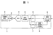
- FIG. 2 is a diagram illustrating a configuration of an inertial sensor according to the first embodiment.
- FIG. 3 is a diagram for explaining the structure of a communication frame in the first embodiment.
- 1 is an overall configuration diagram of a vehicle control system in Embodiment 1.
- FIG. FIG. 5 is a diagram showing a configuration of an inertial sensor in Embodiment 2.
- FIG. 6 is a diagram showing a configuration of a communication frame in the second embodiment.
- FIG. 3 is an overall configuration diagram of a vehicle control system in Embodiment 2.
- FIG. 5 is an overall configuration diagram of a vehicle control system in Embodiment 3.
- the present embodiment realizes brake and throttle control called G-Vectoring control described above for the purpose of suppressing a sudden change in vehicle inertia force in a steady state where no side slip occurs in the vehicle. It is related with the inertial sensor for.
- a brake control called VDC control for controlling an unsteady state in which the vehicle is skidding is known.
- G-Vectoring control and VDC control coexist.
- FIG. 1 is a diagram illustrating a configuration of the inertial sensor according to the first embodiment.
- the inertial sensor 1 includes an acceleration detection element 2, an amplifier unit 3, an ADC (Analogue to Digital Converter) 4, a signal processing unit 5, a first low-pass filter (first filter) 6,
- the sensor module includes a second low-pass filter (second filter) 7, a vehicle control amount calculator 8, and a communication frame generator 9.
- the acceleration detection element 2 that detects acceleration from the outside is an element called a capacitance type so-called MEMS (Micro Electro Mechanical Systems) that captures displacement of the mass generated by application of acceleration, for example, by capacitance change.
- MEMS Micro Electro Mechanical Systems
- capacitance change is converted to voltage signal by C / V (Capacitance to Voltage) conversion.
- the acceleration detection element 2 has a first axis set to extend in the front-rear direction of the vehicle, a second axis set to extend in the vehicle width direction of the vehicle, and extends in the vertical direction of the vehicle.
- the third axis is set as described above, the vehicle traveling direction acceleration that is the acceleration in the axial direction of the first axis, the vehicle lateral acceleration that is the acceleration in the axial direction of the second axis, and the axis of the third axis A vertical acceleration that is a direction acceleration is detected.
- the acceleration detecting element 2 is individually provided corresponding to each axis, and a total of three acceleration detecting elements 2 are provided.
- one acceleration detecting element 2 is provided in all axial directions from the first axis to the third axis. An element that detects acceleration may be used. Moreover, it is not necessary to have all the detection capabilities in the axial direction.
- the amplifier unit 3 has a configuration for converting the electrical signal output from the acceleration detection element 2 to an appropriate level. However, if the range of acceleration required for coexisting G-Vectoring control and VDC control is different, the range of the amplifier 3 may be variable so that the range can be changed according to the application to be applied. There are the following advantages.
- Vectoring control can detect small fluctuations in acceleration finely, VDC control can appropriately detect large fluctuations in acceleration, and a single sensor can satisfy a plurality of different specifications.
- the level constantly varies by time division For example, when processing is performed 100 times per second, 50 times is set as a gain that allows a narrow range to be input, and the remaining 50 times are switched to a gain that allows a wide range to be input without determining the state of the vehicle. Can detect both wide range and narrow range.
- a configuration may be adopted in which two or more amplifier units 3 having different gains are provided in parallel.
- the signal from the acceleration detection element 2 is divided into two and the subsequent circuits are provided in parallel by G-Vectoring control and VDC control, so that optimum detection according to each control can be performed. .
- the voltage level of the voltage signal output from the amplifier unit 3 is converted into a digital value by the ADC 4.
- the signal processing unit 5 in the subsequent stage can be digitized, and low-cost and high-accuracy signal processing can be realized.
- the ADC 4 may have any configuration, and so-called flash type, pipeline type, successive approximation type, and delta sigma type are not limited. Further, it is not always necessary to provide the digital signal by the ADC, and the subsequent processing can be performed by an analog circuit.
- the digital signal that has passed through the ADC 4 is sent to the signal processing unit 5 and processed into an appropriate form as a sensor output value.
- demodulation is performed here.
- the signal processing unit 5 performs synchronous detection of the carrier signal and demodulates it to a baseband signal.
- output signal shaping such as compensation for temperature change, zero point correction, and sensitivity correction is performed.
- the signal processing described above may be constituted by a dedicated LSI, or may be constituted by a DSP and rewritable software corresponding to the DSP.
- a first low-pass filter 6 indicated by LPF (Low Pass Filter) 1 in FIG. 1 performs a filtering process for limiting the signal processed by the signal processing unit 5 to a band for VDC control (first band). And cut unnecessary noise components.
- the second low-pass filter 7 indicated by LPF 2 in FIG. 2 constitutes a filter having a frequency characteristic different from the band for VDC control indicated by the low-pass filter 6, that is, a different cutoff characteristic. Then, a filtering process for limiting the signal processed by the signal processing unit 5 to a band (second band) for G-Vectoring control is performed.
- the signal from the acceleration detection element 2 can be used in a free band regardless of the output frequency characteristic as a sensor defined by the low-pass filter 6.
- the second low-pass filter 7 may have a cut-off characteristic lower than that of the first low-pass filter 6, and vice versa to ensure responsiveness. It is good.
- the second low-pass filter 7 has an infinitely high cut-off characteristic, that is, a structure that does not have any low-pass characteristic, and the acceleration signal before the control amount calculation by the vehicle control amount calculation unit 8 is performed. It is also possible to prevent the occurrence of the phase delay as much as possible. For example, even if the baseband signal is directly transmitted to the vehicle control amount calculation unit 8 to be described later in the next stage, noise removal should be performed separately or indirectly realized by the responsiveness of the actuator. This is because it is possible.
- the band of the second low-pass filter 7 is set to a band wider than the band of the first low-pass filter 6.
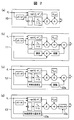
- FIG. 2 is a diagram illustrating an example of a circuit configuration of the vehicle control amount calculation unit.
- the vehicle control amount calculation unit 8 calculates the equation (1) shown in the background art, that is, the lateral acceleration and the lateral jerk (transverse acceleration) by, for example, the configuration of the circuit 10 shown in FIG. A control amount of the traveling direction acceleration according to the differential value) is obtained.
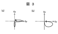
- FIG. 3 is an image of a diagram showing an example of the resultant acceleration applied to the vehicle during cornering.
- FIG. 3A shows the synthesized acceleration of a general driver when there is no G-Vectoring control
- FIG. b) shows the resultant acceleration when G-Vectoring control is applied.
- the horizontal axis of the diagram represents the lateral acceleration G y of the vehicle
- the vertical axis represents the traveling direction acceleration G x .
- the curve time transition of the resultant acceleration when G-Vectoring control shown in Fig. 3 (b) is applied indicates that there is little sudden change in inertial force, and there is no poor ride comfort and unnecessary acceleration / deceleration. Show that.
- the circuit 10 in FIG. 2A is constituted by a digital circuit or DSP software.
- the expression (1) is not necessarily limited to the form, and is not necessarily limited to the configuration of the circuit 10, but it is necessary to be an expression indicating acceleration control in the traveling direction in conjunction with the lateral inertia amount. .
- the acceleration signal derived from the signal of the acceleration detection element 2 mounted on the inertial sensor 1 there may be another input.
- the error can be corrected by inputting the steering angle signal in addition to the acceleration signal, improving the accuracy of the sensor value and increasing the reliability. Can increase the sex.
- the constants of the vehicle control amount calculation unit 8 are held in a state written at the time of shipment by PROM (Programmable Read Only Memory) or Flash ROM (Read Only Memory). However, as will be described later, the constants may be held in RAM (Random Access Memory) in order to dynamically change them.
- the acceleration detection element 2 and the vehicle control amount calculation unit 8 are closed, that is, the acceleration detection element 2 and the vehicle control amount calculation unit 8 are integrally formed as a module, and a signal is generated in the module.
- the acceleration Ac given as a target is calculated with respect to the actual acceleration Aa in the vehicle direction, and the acceleration Aa after passing through the control delay and the vehicle dynamics delay.
- 'Is equal to the difference between the actual acceleration Aa and the target acceleration Ac (Aa-Ac), and adjustment is made to dynamically change the gain and bias of the vehicle control amount so that this is correct be able to.
- the weight and the balance differed when the vehicle type was different, the number of passengers in the car changed, the road surface and the state of the vehicle (whether it was a slope, whether it was raining, etc.) Therefore, the appropriate operation amount of the brake and the throttle opening with respect to the desired acceleration change amount changes.
- the inertial sensor 1 can be mounted on any vehicle without special prior adjustment regardless of the vehicle type, and Even in situations where the number of occupants changes drastically from 1 to 8 people, it is possible to give an appropriate acceleration in the vehicle traveling direction (vehicle control amount) without making adjustments, reducing adjustment costs Is effective.
- the fact that the acceleration detection element 2 and the vehicle control amount calculation unit 8 are closed in the inertial sensor 1 is utilized separately, and the current vehicle inclination state is added to the acceleration sensor bias component without additional hardware.
- the brake operation amount and the throttle opening gain are adjusted in advance.
- the acceleration detection element 2 in the vehicle traveling direction has g ⁇ sin ( ⁇ ) Appears, and the gravitational acceleration applied to the acceleration detection element 2 in the vertical direction of the vehicle decreases to g ⁇ cos ( ⁇ ). That is, it is possible to determine the slope by analyzing the signal component of at least the uniaxial acceleration detection element 2.
- the brake control amount is increased and the throttle opening control amount is decreased on the downhill, and vice versa on the uphill.
- Inertia change caused by additional vehicle control applied to correct the error after vehicle control by adjusting in advance to reduce the brake control amount and increase the throttle opening control amount Can be reduced and deterioration of ride comfort can be prevented.
- the detection of the acceleration, the processing, the estimation of the vehicle state in the inertial sensor 1, and the adjustment amount corresponding to the situation are all closed so that the vehicle control amount changes like a slope. Even in a difficult situation, an appropriate vehicle control amount can be given, which is effective for improving the ride comfort.
- the change amount of the acceleration detection element caused by the control can be constantly calculated without adding any other hardware.
- the control amount may fall within a certain range.
- the circuit 13 shown in FIG. 2D has a configuration in which the acceleration change amount measuring unit 13a measures the acceleration change amount and the limiter 13b limits the vehicle control amount G xc based on the acceleration change amount.
- the user can set the desired maximum control amount by himself / herself, or set the maximum control amount according to the vehicle type when the vehicle is shipped so that the driver and passengers do not experience such control as to feel danger or fear.
- the maximum value of the appropriate control amount can be provided at a low cost.
- the feedback configuration shown in the circuit 11, the slope detection configuration shown in the circuit 12, and the configuration with limiter shown in the circuit 13 can all coexist, and a circuit combining all the configurations of the circuits 11 to 13 is made.
- a circuit in which two configurations are selected from each configuration and combined can be provided.
- FIG. 4 is a diagram for explaining an example of the structure of a communication frame in the present embodiment.
- the communication frame generation unit 9 has a configuration (sensor signal output unit) that generates a communication frame having acceleration and a vehicle control amount and outputs it as a sensor signal.
- the vehicle traveling direction acceleration 1 and the vehicle lateral direction acceleration 2 filtered by the first low-pass filter 6 and limited to the band (first band) for VDC control, and the vehicle control.
- the amount is transmitted in the same frame.
- Fig. 4 as an example, frames are assigned to different information every 2 bytes.
- the communication frame generation unit 9 outputs an acceleration of at least one axis and a vehicle control amount.
- the frames are not necessarily the same, but frame division is not appropriate from the viewpoint of reducing delay time.
- CRC Cyclic Redundancy Check
- CRC Cyclic Redundancy Check
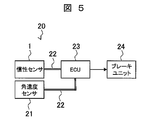
- FIG. 5 is an overall configuration diagram of a vehicle control system using the inertial sensor shown in FIG.
- the vehicle control system 20 includes an inertial sensor 1, an angular velocity sensor 21, an ECU (Electric Control Unit) 23, and a brake unit 24.
- the angular velocity sensor 21 has a configuration equivalent to the configuration of reference numerals 2 to 6 of the inertial sensor 1 shown in FIG. 1, and includes an angular velocity detection element 38, an amplifier unit, an ADC, a signal processing unit, and a low-pass filter. It consists of modules (not shown).
- the inertial sensor 1 and the angular velocity sensor 21 are connected to the ECU 23 via communication lines 22, respectively.
- the communication line 22 is a communication unit that realizes communication between the inertial sensor 1 and the angular velocity sensor 21 and the ECU 23, and uses, for example, a digital communication method called SPI (Serial Peripheral Interface) communication.
- SPI Serial Peripheral Interface
- the ECU 23 receives the acceleration, the angular velocity, and the vehicle control amount from the inertial sensor 1 and the angular velocity sensor 21, and in order to actually perform VDC control and G-Vectoring control of the vehicle accordingly, the brake unit 24 and the throttle opening degree Activate (not shown).
- VDC control since control is performed using steering angle and vehicle speed information together, such information is input to the ECU 23, but is not shown here.
- the vehicle control amount output from the inertial sensor 1 does not include a delay generating element, and therefore suppresses a delay until the braking force or the acceleration force is generated by the control, and further the dynamic condition An appropriate control amount corresponding to the change can be output without delay. For this reason, the vehicle control which suppresses the unnatural inertia force given to a driver and a passenger, and maintains favorable riding comfort irrespective of conditions is realized. Furthermore, since additional hardware is not required for coexistence with VDC control, it is advantageous in terms of cost in that it does not require hardware addition from a vehicle equipped with VDC control.
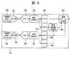
- FIG. 6 is a diagram illustrating a configuration of the inertial sensor according to the second embodiment.
- the inertial sensor 31 includes an acceleration detection element 32, an amplifier unit 33, an ADC 34, a signal processing unit 35, a first low-pass filter (first filter) 36, and a second low-pass filter. (Second filter) 37, angular velocity detection element 38, amplifier unit 39, ADC 40, signal processing unit 41, third low-pass filter (third filter) 42, fourth low-pass filter (fourth filter)
- the sensor module includes a filter 43, a vehicle control amount calculation unit 44, and a communication frame generation unit 45.
- At least one axis or more angular velocity detection element 38 and its associated circuit are provided in the inertial sensor 31 to form a sensor module.
- the configurations of reference numerals 32 to 37 are the same as the configurations of reference numerals 2 to 7 of the first embodiment, detailed description thereof will be omitted.
- the mounting form of the angular velocity detection element 38 and the acceleration detection element 32 may be a single chip or may be divided into multiple chips. However, with respect to the circuit mounting form at the subsequent stage, the communication frame generation unit 45 is made a consistent single chip configuration rather than a multi-chip configuration, thereby reducing communication delay.
- the angular velocity detection element 38 is a capacitance type detection element that captures, for example, displacement of a mass mass caused by Coriolis force generated by application of angular velocity by a capacitance change, and converts the capacitance change into a voltage signal by C / V conversion.
- the angular velocity detection element 38 calculates the angular velocity in the roll direction that is the angular velocity around the axis of the first axis, the angular velocity in the pitching direction that is around the axis of the second axis, and the angular velocity in the yaw direction that is around the axis of the third axis. To detect.
- the angular velocity detecting element 38 is provided for each axis, and a total of three angular velocity detecting elements 38 are provided.
- one angular velocity detecting element 38 is capable of measuring angular velocities around all axes from the first axis to the third axis. What is to be detected may be used.
- the configurations of the amplifier unit 39, the ADC 40, and the signal processing unit 41 are the same as those of the amplifier unit 3, the ADC 4, and the signal processing unit 5 of the first embodiment, and thus description thereof is omitted.
- the angular velocity detection signal processed by the signal processing unit 41 is limited to the band for VDC control (third band). Filtering process to cut unnecessary noise components. At this time, the frequency characteristics may be the same as or different from those of the first low-pass filter 36 indicated by LPF1.
- the fourth low-pass filter 43 (fourth filter) indicated by LPF4 has a frequency characteristic different from the band for VDC control indicated by the third low-pass filter 42, that is, a different cutoff characteristic.
- a filter is configured to perform a filtering process for limiting the angular velocity detection signal processed by the signal processing unit 41 to a band (fourth band) for G-Vectoring control. This means that the signal from the angular velocity detecting element 38 can be used in a free band regardless of the output frequency characteristic as a sensor defined by the low-pass filter 42.
- the fourth low-pass filter 43 may have a cut-off characteristic lower than that of the third low-pass filter 42, and in order to ensure responsiveness, The reverse is also possible.
- the fourth low-pass filter 43 may have an infinitely high cut-off characteristic, that is, a structure that does not have any low-pass characteristic.
- This configuration is a configuration in which the baseband signal is transmitted directly to the vehicle control amount calculation unit 44 in the next stage in order not to cause a phase delay of the angular velocity signal until the control amount calculation, and noise removal is performed separately. It can be realized indirectly by the responsiveness of the actuator.
- the band of the fourth low-pass filter 43 is set to a wider band than the band of the third low-pass filter 42.
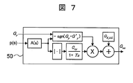
- FIG. 7 is a diagram illustrating an example of a circuit configuration of the vehicle control amount calculation unit.
- the vehicle control amount calculation unit 44 calculates the control amount of the traveling direction acceleration according to the calculation of the above-described equation (1), that is, the lateral acceleration and the lateral jerk of the vehicle, for example, by the configuration of the circuit 50 shown in FIG. obtain.
- the angular velocity around the first axis that is the angular velocity around the axis of the first axis of the vehicle, that is, the angular velocity in the roll direction of the vehicle is used.
- a circuit configuration for estimating jerk is provided.
- the lateral jerk is the transfer function expressed by the following equation (2). Can be estimated.
- a (s) is the transfer function that converts the angular velocity in the roll direction into lateral jerk
- T1 and T2 are appropriate time constants
- Kx is the roll stiffness
- ms is the sprung mass
- g is the gravitational acceleration
- h is the roll
- the height from the center to the center of gravity, p (s), is the angular velocity in the roll direction.
- the lateral jerk can be integrated to obtain the lateral acceleration, so that the consistency with the signal is judged from the acceleration detecting element 32, or the G-Vectoring control is performed without using the signal of the acceleration detecting element 32. It can also be realized.
- acceleration and angular velocity are necessary sensor information for VDC control, so both controls can be realized with one sensor, dedicated for G-Vectoring control and VDC control respectively. It is not necessary to provide this sensor, and the installation cost can be further reduced.
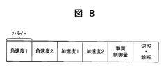
- FIG. 8 is a diagram for explaining an example of the structure of a communication frame in the present embodiment.
- the communication frame generation unit 45 has a configuration (sensor signal output unit) that generates a communication frame having acceleration, angular velocity, and vehicle control amount and outputs it as a sensor signal.
- the vehicle traveling direction acceleration 1 and the vehicle lateral acceleration 2 filtered by the first low-pass filter 36 and limited to the band for VDC control (first band), and the third low-pass filter 36 are used.
- the roll direction angular velocity 1 and the pitching direction angular velocity 2 filtered by the pass filter 42 and limited to the band for VDC control (third band) and the vehicle control amount G xc are transmitted in the same frame.
- frames are assigned to different information every 2 bytes.
- the communication frame generation unit 45 outputs an angular velocity of at least one axis, an acceleration of one axis or more, and a vehicle control amount.
- the frames are not necessarily the same, but frame division is not appropriate from the viewpoint of reducing delay time.
- CRC Cyclic Redundancy Check
- CRC Cyclic Redundancy Check
- FIG. 9 is an overall configuration diagram of a vehicle control system using the inertial sensor shown in FIG.
- the vehicle control system 60 includes an inertial sensor 31, an ECU 62, and a brake unit 63.
- the inertial sensor 31 is connected to the ECU 62 via the communication line 61.
- the communication line 61 is a communication unit that realizes communication between the inertial sensor 31 and the ECU 62, and uses, for example, a digital communication method called SPI communication.
- the ECU 62 receives the acceleration, angular velocity, and vehicle control amount from the inertial sensor 31, and in order to actually give VDC control and G-Vectoring control to the vehicle accordingly, the brake operation amount and throttle valve (see FIG. (Not shown) to control the throttle opening.
- VDC control since control is performed using steering angle and vehicle speed information together, such information is input to the ECU 62, but it is not shown here.
- the vehicle control amount output from the inertial sensor 31 omits the delay generating element as described above, and therefore suppresses the delay until the generation of the braking force or the acceleration force due to the control. It is possible to output an appropriate control amount corresponding to a general change in conditions without delay. For this reason, the vehicle control which suppresses the unnatural inertia force given to a driver and a passenger, and maintains favorable riding comfort irrespective of conditions is realized. Furthermore, since additional hardware is not required for coexistence with VDC control, it is advantageous in terms of cost in that it does not require hardware addition from a vehicle equipped with VDC control.
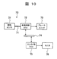
- FIG. 10 is an overall configuration diagram of the vehicle control system according to the third embodiment. What is characteristic in the present embodiment is that the driver is notified that G-Vectoring control is being executed.
- the vehicle control system 70 includes an inertial sensor 31, a vehicle control ECU 72, a brake unit 73, a communication bus 74, an entertainment system ECU 75, and a monitor 76.
- the inertial sensor 31 is connected to the vehicle control ECU 72 via the communication line 71.
- the communication line 71 is a communication unit that realizes communication between the inertial sensor 31 and the vehicle control ECU 72, and uses, for example, SPI communication.
- the vehicle control ECU 72 controls the brake operation amount of the brake unit 73 and the throttle opening of a throttle valve (not shown).
- the communication bus 74 is a communication bus to which a large number of terminals can be connected, such as a CAN (Controller-Area-Network) bus.
- the vehicle control ECU 72 notifies the entertainment system ECU 75 of the acceleration and the vehicle control amount via the communication bus 74.
- the monitor 76 is set at a position where the driver can visually recognize the vehicle interior, and displays the acceleration on the horizontal plane applied to the vehicle.
- the monitor 76 shows a diagram image in which the horizontal axis represents the lateral acceleration of the vehicle and the vertical axis represents the traveling direction acceleration, and further, the vehicle control amount is also illustrated.
Landscapes
- Physics & Mathematics (AREA)
- General Physics & Mathematics (AREA)
- Engineering & Computer Science (AREA)
- Signal Processing (AREA)
- Radar, Positioning & Navigation (AREA)
- Remote Sensing (AREA)
- Control Of Driving Devices And Active Controlling Of Vehicle (AREA)
- Vehicle Body Suspensions (AREA)
Priority Applications (2)
| Application Number | Priority Date | Filing Date | Title |
|---|---|---|---|
| US14/001,634 US9086427B2 (en) | 2011-03-11 | 2012-01-11 | Inertial sensor |
| DE112012001187.2T DE112012001187B4 (de) | 2011-03-11 | 2012-01-11 | Trägheitssensor |
Applications Claiming Priority (2)
| Application Number | Priority Date | Filing Date | Title |
|---|---|---|---|
| JP2011-054584 | 2011-03-11 | ||
| JP2011054584A JP5690176B2 (ja) | 2011-03-11 | 2011-03-11 | 慣性センサ |
Publications (1)
| Publication Number | Publication Date |
|---|---|
| WO2012124358A1 true WO2012124358A1 (ja) | 2012-09-20 |
Family
ID=46830439
Family Applications (1)
| Application Number | Title | Priority Date | Filing Date |
|---|---|---|---|
| PCT/JP2012/050390 Ceased WO2012124358A1 (ja) | 2011-03-11 | 2012-01-11 | 慣性センサ |
Country Status (4)
| Country | Link |
|---|---|
| US (1) | US9086427B2 (https=) |
| JP (1) | JP5690176B2 (https=) |
| DE (1) | DE112012001187B4 (https=) |
| WO (1) | WO2012124358A1 (https=) |
Cited By (2)
| Publication number | Priority date | Publication date | Assignee | Title |
|---|---|---|---|---|
| JP2016519282A (ja) * | 2013-03-11 | 2016-06-30 | クアルコム,インコーポレイテッド | 慣性センサの帯域幅および時間遅延整合 |
| CN108099918A (zh) * | 2016-11-23 | 2018-06-01 | 百度(美国)有限责任公司 | 用于确定自主车辆的命令延迟的方法 |
Families Citing this family (11)
| Publication number | Priority date | Publication date | Assignee | Title |
|---|---|---|---|---|
| DE102014113162B4 (de) * | 2014-09-12 | 2016-05-12 | Analog Devices Global | Verfahren für einen verbesserten Datendurchsatz in einem Kommunikationssystem und Kommunikationssystem |
| ITUB20151063A1 (it) * | 2015-05-28 | 2016-11-28 | Area Prefabbricati S P A | Sensore accelerometrico per il monitoraggio sismico di strutture |
| JP6198181B2 (ja) | 2015-11-06 | 2017-09-20 | マツダ株式会社 | 車両用挙動制御装置 |
| JP6252992B2 (ja) | 2015-11-06 | 2017-12-27 | マツダ株式会社 | 車両用挙動制御装置 |
| JP6194940B2 (ja) | 2015-11-06 | 2017-09-13 | マツダ株式会社 | 車両用挙動制御装置 |
| JP6252993B2 (ja) | 2015-11-06 | 2017-12-27 | マツダ株式会社 | 車両用挙動制御装置 |
| JP6252994B2 (ja) | 2015-12-22 | 2017-12-27 | マツダ株式会社 | 車両用挙動制御装置 |
| JP6213904B1 (ja) | 2016-06-30 | 2017-10-18 | マツダ株式会社 | 車両用挙動制御装置 |
| US10401249B2 (en) | 2016-10-11 | 2019-09-03 | Caterpillar Inc. | Methods and systems for detecting unbalanced payload condition in machines |
| US12162628B2 (en) * | 2019-12-27 | 2024-12-10 | Simmonds Precision Products, Inc. | Configurable sensing systems and methods for configuration |
| DE102021204681A1 (de) * | 2021-05-10 | 2022-11-10 | Robert Bosch Gesellschaft mit beschränkter Haftung | Mikromechanischer Inertialsensor |
Citations (4)
| Publication number | Priority date | Publication date | Assignee | Title |
|---|---|---|---|---|
| JP2005104339A (ja) * | 2003-09-30 | 2005-04-21 | Mitsubishi Fuso Truck & Bus Corp | 車両のロールオーバ抑制制御装置 |
| JP2006290133A (ja) * | 2005-04-08 | 2006-10-26 | Nissan Motor Co Ltd | 車両制御システム |
| JP2009107447A (ja) * | 2007-10-29 | 2009-05-21 | Hitachi Ltd | 車両制御装置 |
| JP2010162911A (ja) * | 2009-01-13 | 2010-07-29 | Hitachi Automotive Systems Ltd | 車両の運動制御装置 |
Family Cites Families (8)
| Publication number | Priority date | Publication date | Assignee | Title |
|---|---|---|---|---|
| US3661347A (en) | 1969-07-16 | 1972-05-09 | Us Navy | Gain changer |
| JPH0943269A (ja) * | 1995-07-28 | 1997-02-14 | Omron Corp | 加速度トランスデューサ |
| JPH10282136A (ja) * | 1997-04-08 | 1998-10-23 | Denso Corp | 加速度センサ |
| DE10164108A1 (de) * | 2001-12-24 | 2003-07-03 | Wabco Gmbh & Co Ohg | Verfahren für die Funktionsprüfung eines Querbeschleunigungssensors |
| JP2005075041A (ja) * | 2003-08-28 | 2005-03-24 | Mitsubishi Electric Corp | ロールオーバ判定装置 |
| JP5144023B2 (ja) | 2006-04-07 | 2013-02-13 | Jsr株式会社 | 膜−電極接合体 |
| US8406959B2 (en) | 2009-02-20 | 2013-03-26 | Trw Automotive U.S. Llc | Method and apparatus for controlling an actuatable restraint device using a side pressure sensor |
| JP5185873B2 (ja) * | 2009-03-30 | 2013-04-17 | 本田技研工業株式会社 | 車両横滑り運動状態量推定装置 |
-
2011
- 2011-03-11 JP JP2011054584A patent/JP5690176B2/ja not_active Expired - Fee Related
-
2012
- 2012-01-11 US US14/001,634 patent/US9086427B2/en not_active Expired - Fee Related
- 2012-01-11 DE DE112012001187.2T patent/DE112012001187B4/de not_active Expired - Fee Related
- 2012-01-11 WO PCT/JP2012/050390 patent/WO2012124358A1/ja not_active Ceased
Patent Citations (4)
| Publication number | Priority date | Publication date | Assignee | Title |
|---|---|---|---|---|
| JP2005104339A (ja) * | 2003-09-30 | 2005-04-21 | Mitsubishi Fuso Truck & Bus Corp | 車両のロールオーバ抑制制御装置 |
| JP2006290133A (ja) * | 2005-04-08 | 2006-10-26 | Nissan Motor Co Ltd | 車両制御システム |
| JP2009107447A (ja) * | 2007-10-29 | 2009-05-21 | Hitachi Ltd | 車両制御装置 |
| JP2010162911A (ja) * | 2009-01-13 | 2010-07-29 | Hitachi Automotive Systems Ltd | 車両の運動制御装置 |
Cited By (2)
| Publication number | Priority date | Publication date | Assignee | Title |
|---|---|---|---|---|
| JP2016519282A (ja) * | 2013-03-11 | 2016-06-30 | クアルコム,インコーポレイテッド | 慣性センサの帯域幅および時間遅延整合 |
| CN108099918A (zh) * | 2016-11-23 | 2018-06-01 | 百度(美国)有限责任公司 | 用于确定自主车辆的命令延迟的方法 |
Also Published As
| Publication number | Publication date |
|---|---|
| JP5690176B2 (ja) | 2015-03-25 |
| US9086427B2 (en) | 2015-07-21 |
| DE112012001187T5 (de) | 2013-12-05 |
| DE112012001187B4 (de) | 2022-04-14 |
| JP2012189508A (ja) | 2012-10-04 |
| US20130345901A1 (en) | 2013-12-26 |
Similar Documents
| Publication | Publication Date | Title |
|---|---|---|
| JP5690176B2 (ja) | 慣性センサ | |
| CN103661395B (zh) | 动态道路坡度估计 | |
| CN103661352B (zh) | 静态道路坡度估计 | |
| JP6393827B2 (ja) | 車両の走行制御装置 | |
| US8165742B2 (en) | System and method for compensating sensor signals | |
| JP6178044B2 (ja) | 自動車の重心の連続計算 | |
| US20090085309A1 (en) | Suspension control apparatus | |
| US20130332030A1 (en) | Intelligent vehicle sensor device | |
| CN101497321A (zh) | 自适应座椅系统及座椅调节方法 | |
| CN101389506B (zh) | 车辆的高度控制装置 | |
| JP2012218736A (ja) | 積荷情報に基づいて重心補償を行う自動車動的制御システム | |
| CN104955690A (zh) | 车辆行驶控制装置 | |
| JP5398581B2 (ja) | サスペンション制御装置 | |
| US10661785B2 (en) | Systems and methods for integrated chassis control in ground vehicles | |
| WO2024048323A1 (ja) | 車両制御装置、車両制御方法および車両制御システム | |
| CN114368385B (zh) | 巡航控制方法和装置、电子设备和存储介质 | |
| KR102766848B1 (ko) | 차량 제어 장치 및 서스펜션 시스템 | |
| US8818642B2 (en) | Control of active vehicle devices during cornering | |
| JP7059341B1 (ja) | サスペンション制御装置、車両およびサスペンション制御方法 | |
| CN103068656A (zh) | 用于车辆系统的控制模块、车辆系统以及具有这种车辆系统的车辆 | |
| CN102458950B (zh) | 用于产生作用于机动车的车轮的力矩差的方法 | |
| CN118810792A (zh) | 识别路面类型的方法、装置、车辆及存储介质 | |
| KR101645708B1 (ko) | 차량의 가속도 센서 보정장치 및 그 보정방법 | |
| KR101459683B1 (ko) | 자동차 및 그 제어방법 | |
| CN117644856A (zh) | 车辆控制方法、装置、控制器及存储介质 |
Legal Events
| Date | Code | Title | Description |
|---|---|---|---|
| 121 | Ep: the epo has been informed by wipo that ep was designated in this application |
Ref document number: 12757517 Country of ref document: EP Kind code of ref document: A1 |
|
| WWE | Wipo information: entry into national phase |
Ref document number: 14001634 Country of ref document: US |
|
| WWE | Wipo information: entry into national phase |
Ref document number: 1120120011872 Country of ref document: DE Ref document number: 112012001187 Country of ref document: DE |
|
| 122 | Ep: pct application non-entry in european phase |
Ref document number: 12757517 Country of ref document: EP Kind code of ref document: A1 |