WO2012124312A1 - 光音響画像化装置および光音響画像化方法並びに光音響画像化装置用プローブ - Google Patents
光音響画像化装置および光音響画像化方法並びに光音響画像化装置用プローブ Download PDFInfo
- Publication number
- WO2012124312A1 WO2012124312A1 PCT/JP2012/001710 JP2012001710W WO2012124312A1 WO 2012124312 A1 WO2012124312 A1 WO 2012124312A1 JP 2012001710 W JP2012001710 W JP 2012001710W WO 2012124312 A1 WO2012124312 A1 WO 2012124312A1
- Authority
- WO
- WIPO (PCT)
- Prior art keywords
- piezoelectric body
- probe
- imaging apparatus
- ultrasonic
- photoacoustic imaging
- Prior art date
- Legal status (The legal status is an assumption and is not a legal conclusion. Google has not performed a legal analysis and makes no representation as to the accuracy of the status listed.)
- Ceased
Links
Images

Classifications
-
- A—HUMAN NECESSITIES
- A61—MEDICAL OR VETERINARY SCIENCE; HYGIENE
- A61B—DIAGNOSIS; SURGERY; IDENTIFICATION
- A61B5/00—Measuring for diagnostic purposes; Identification of persons
- A61B5/0093—Detecting, measuring or recording by applying one single type of energy and measuring its conversion into another type of energy
- A61B5/0095—Detecting, measuring or recording by applying one single type of energy and measuring its conversion into another type of energy by applying light and detecting acoustic waves, i.e. photoacoustic measurements
-
- A—HUMAN NECESSITIES
- A61—MEDICAL OR VETERINARY SCIENCE; HYGIENE
- A61B—DIAGNOSIS; SURGERY; IDENTIFICATION
- A61B8/00—Diagnosis using ultrasonic, sonic or infrasonic waves
- A61B8/44—Constructional features of the ultrasonic, sonic or infrasonic diagnostic device
- A61B8/4411—Device being modular
-
- A—HUMAN NECESSITIES
- A61—MEDICAL OR VETERINARY SCIENCE; HYGIENE
- A61B—DIAGNOSIS; SURGERY; IDENTIFICATION
- A61B8/00—Diagnosis using ultrasonic, sonic or infrasonic waves
- A61B8/44—Constructional features of the ultrasonic, sonic or infrasonic diagnostic device
- A61B8/4427—Device being portable or laptop-like
-
- A—HUMAN NECESSITIES
- A61—MEDICAL OR VETERINARY SCIENCE; HYGIENE
- A61B—DIAGNOSIS; SURGERY; IDENTIFICATION
- A61B8/00—Diagnosis using ultrasonic, sonic or infrasonic waves
- A61B8/44—Constructional features of the ultrasonic, sonic or infrasonic diagnostic device
- A61B8/4444—Constructional features of the ultrasonic, sonic or infrasonic diagnostic device related to the probe
- A61B8/4455—Features of the external shape of the probe, e.g. ergonomic aspects
-
- A—HUMAN NECESSITIES
- A61—MEDICAL OR VETERINARY SCIENCE; HYGIENE
- A61B—DIAGNOSIS; SURGERY; IDENTIFICATION
- A61B8/00—Diagnosis using ultrasonic, sonic or infrasonic waves
- A61B8/44—Constructional features of the ultrasonic, sonic or infrasonic diagnostic device
- A61B8/4483—Constructional features of the ultrasonic, sonic or infrasonic diagnostic device characterised by features of the ultrasound transducer
-
- A—HUMAN NECESSITIES
- A61—MEDICAL OR VETERINARY SCIENCE; HYGIENE
- A61B—DIAGNOSIS; SURGERY; IDENTIFICATION
- A61B8/00—Diagnosis using ultrasonic, sonic or infrasonic waves
- A61B8/52—Devices using data or image processing specially adapted for diagnosis using ultrasonic, sonic or infrasonic waves
- A61B8/5215—Devices using data or image processing specially adapted for diagnosis using ultrasonic, sonic or infrasonic waves involving processing of medical diagnostic data
- A61B8/5238—Devices using data or image processing specially adapted for diagnosis using ultrasonic, sonic or infrasonic waves involving processing of medical diagnostic data for combining image data of patient, e.g. merging several images from different acquisition modes into one image
- A61B8/5261—Devices using data or image processing specially adapted for diagnosis using ultrasonic, sonic or infrasonic waves involving processing of medical diagnostic data for combining image data of patient, e.g. merging several images from different acquisition modes into one image combining images from different diagnostic modalities, e.g. ultrasound and X-ray
-
- B—PERFORMING OPERATIONS; TRANSPORTING
- B06—GENERATING OR TRANSMITTING MECHANICAL VIBRATIONS IN GENERAL
- B06B—METHODS OR APPARATUS FOR GENERATING OR TRANSMITTING MECHANICAL VIBRATIONS OF INFRASONIC, SONIC, OR ULTRASONIC FREQUENCY, e.g. FOR PERFORMING MECHANICAL WORK IN GENERAL
- B06B1/00—Methods or apparatus for generating mechanical vibrations of infrasonic, sonic, or ultrasonic frequency
- B06B1/02—Methods or apparatus for generating mechanical vibrations of infrasonic, sonic, or ultrasonic frequency making use of electrical energy
- B06B1/06—Methods or apparatus for generating mechanical vibrations of infrasonic, sonic, or ultrasonic frequency making use of electrical energy operating with piezoelectric effect or with electrostriction
- B06B1/0607—Methods or apparatus for generating mechanical vibrations of infrasonic, sonic, or ultrasonic frequency making use of electrical energy operating with piezoelectric effect or with electrostriction using multiple elements
Definitions
- the present invention relates to a photoacoustic imaging apparatus, that is, an apparatus for irradiating a subject such as a living tissue with light and imaging the subject based on an acoustic wave generated by the light irradiation.
- the present invention relates to a photoacoustic imaging apparatus having a function of acquiring an image.
- the present invention also relates to a method for performing the above-described photoacoustic imaging.
- the present invention relates to a probe used in such a photoacoustic imaging apparatus.
- Patent Document 1 and Non-Patent Document 1 a photoacoustic imaging apparatus that images the inside of a living body using a photoacoustic effect is known.
- pulsed light such as pulsed laser light is irradiated into the living body.
- the living tissue that has absorbed the energy of the pulsed light undergoes volume expansion due to heat and generates an acoustic wave (acoustic signal). Therefore, it is possible to detect this acoustic wave with an ultrasonic probe or the like and visualize the inside of the living body based on the detection signal.
- an ultrasonic imaging apparatus using an ultrasonic probe is also conventionally known.
- This type of ultrasonic probe is provided with an ultrasonic transducer (hereinafter abbreviated as UT) at the tip, and in many cases, a backing material, a piezoelectric body and electrodes sandwiching this, an acoustic matching layer, an acoustic lens, etc. It is composed of
- UT ultrasonic transducer
- the ultrasonic imaging apparatus ultrasonic waves are irradiated from the UT to the subject (human body), and reflected ultrasonic waves from the subject are received by the UT.
- An ultrasonic image is obtained by electrically processing the reflected ultrasonic detection signal.
- an ultrasonic tomographic image by irradiating while scanning with ultrasonic waves.
- a method for obtaining an ultrasonic tomographic image a mechanical scan scanning method in which a UT is mechanically rotated, rocked, or slid, or a plurality of UTs arranged in an array (hereinafter referred to as a UT array) and driven UTs are arranged.
- An electronic scan scanning method that is selectively switched by an electronic switch or the like is known.
- the ultrasonic probe as described above can detect an acoustic wave as well as an ultrasonic wave
- an apparatus capable of acquiring both a photoacoustic image and an ultrasonic image has been proposed. That is, in such an apparatus, a light irradiation unit that irradiates light toward the subject is added to the ultrasonic probe, and an acoustic wave emitted from the subject that receives light from the light irradiation unit is transmitted to the UT of the ultrasonic probe. Is to be detected.
- JP 2005-21380 A Japanese Patent Laid-Open No. 06-148154
- the present invention efficiently detects both an ultrasonic wave and an acoustic wave, and generates a high-quality ultrasonic image and a photoacoustic image.
- the purpose is to enable acquisition.
- the probe for a photoacoustic imager is: A light irradiation unit that emits light to be irradiated on the subject to generate an acoustic wave; An ultrasonic wave generating means for generating an ultrasonic wave applied to the subject; A first piezoelectric body for detecting the ultrasonic wave reflected by the subject; In a probe for a photoacoustic imaging apparatus comprising: a second piezoelectric body that detects an acoustic wave emitted from a subject by the light irradiation.
- the first piezoelectric body is a piezoelectric body made of an inorganic material
- the second piezoelectric body is a piezoelectric body made of an organic material.
- an acoustic matching layer that also serves as an electrode common to the first and second piezoelectric bodies is formed between the first and second piezoelectric bodies.
- the second piezoelectric body is disposed closer to the subject than the first piezoelectric body.
- the acoustic matching layer contains a metal such as silver.
- the acoustic matching layer containing a metal is composed of a composite containing a metal in an organic material. Such an organic material desirably has adhesiveness.
- the above-mentioned metal is preferably made of metal nanoparticles.
- the acoustic matching layer may be composed of a material having a relatively low conductivity, or a surface of a non-conductive material covered with a conductive material.
- the photoacoustic imaging apparatus includes the probe according to the present invention as described above.
- the photoacoustic imaging method uses the probe according to the present invention as described above to acquire an ultrasonic image based on a signal output from the first piezoelectric body, and to obtain a signal output from the second piezoelectric body.
- a photoacoustic image is acquired based on the above.
- the ultrasonic wave irradiated to a subject such as a living tissue for acquiring an ultrasonic image is generally limited to a frequency range of 1 to 40 MHz (eg, 6 dB such as 2 to 5 MHz, 4 to 10 MHz, and 5 to 12 MHz). A region having a specific bandwidth of about 80% is used.
- the frequency of an acoustic wave emitted from a subject such as a living tissue by light irradiation is about 1 to 40 MHz, but the acoustic wave covers the entire frequency range of about 1 to 40 MHz.
- a piezoelectric body made of an inorganic material shows a very high detection sensitivity in a relatively narrow band (about 80% in a 6 dB ratio band), but a piezoelectric body made of an organic material has a clear resonance point in the probe configuration. Since it is not shown, it has a relatively high detection sensitivity over a very wide frequency band.
- the first piezoelectric body made of an inorganic material having the above characteristics is used to detect a relatively low frequency ultrasonic wave with a low biological attenuation with a very high sensitivity. Since the acoustic wave is detected over a very wide frequency range from a low frequency to a high frequency by the second piezoelectric body made of the organic material having the above characteristics, the reflected ultrasonic wave is efficiently obtained according to this probe, and Acoustic waves can be detected widely.
- the photoacoustic imaging apparatus of the present invention using the probe according to the present invention can efficiently detect reflected ultrasonic waves and acoustic waves, and can acquire high-quality ultrasonic images and photoacoustic images.
- the perspective view which shows the whole shape of the photoacoustic imaging device by one Embodiment of this invention The partially broken perspective view which shows the probe for photoacoustic imaging devices by one Embodiment of this invention
- FIG. 1 shows an overall shape of a photoacoustic imaging apparatus according to an embodiment of the present invention
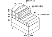
- FIG. 2 shows a probe used therein
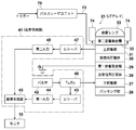
- FIG. 3 shows the electrical configuration of the apparatus of this embodiment.
- the apparatus of this embodiment is configured as an ultrasonic diagnostic apparatus 2, and as shown in FIG. 1, this ultrasonic diagnostic apparatus 2 basically includes a portable ultrasonic observation device 10 and an external ultrasonic probe. (Probe for photoacoustic imaging device) 11 and a pulse laser unit 70.
- this ultrasonic diagnostic apparatus 2 basically includes a portable ultrasonic observation device 10 and an external ultrasonic probe. (Probe for photoacoustic imaging device) 11 and a pulse laser unit 70.
- the portable ultrasonic observation device 10 includes an apparatus main body 12 and a cover 13. On the upper surface of the apparatus body 12, an operation unit 14 provided with a plurality of buttons and a trackball for inputting various operation instructions to the portable ultrasonic observation device 10 is arranged. A monitor 15 for displaying various operation screens including an ultrasonic image is provided on the inner surface of the cover 13.
- the cover 13 is attached to the apparatus main body 12 via a hinge 16, and the opening position shown in the figure that exposes the operation unit 14 and the monitor 15, the upper surface of the apparatus main body 12, and the inner surface of the cover 13 face each other. It is rotatable between a closed position (not shown) that covers and protects the unit 14 and the monitor 15.
- a grip (not shown) is attached to the side surface of the apparatus main body 12, and the portable ultrasonic observer 10 can be carried with the apparatus main body 12 and the cover 13 closed.
- a probe connection portion 17 and a laser unit connection portion 72 to which the ultrasonic probe 11 is detachably connected are provided on the other side surface of the apparatus main body 12.
- the ultrasonic probe 11 includes a scanning head 18 held by an operator and applied to a subject, a connector 19 connected to the probe connecting portion 17, and a cable 20 connecting them.
- An ultrasonic transducer array (hereinafter abbreviated as UT array) 21 is built in the tip of the scanning head 18.
- the UT array 21 includes a backing material 26, a lower electrode 27, an ultrasonic transmission / reception piezoelectric body 28, a first acoustic matching layer 29, an acoustic wave on a flat base 25 made of glass-epoxy resin or the like.
- the wave receiving piezoelectric member 30, the upper electrode 31, the second acoustic matching layer 32, and the acoustic lens 33 are sequentially laminated.
- the backing material 26 regulates the free vibration of the ultrasonic transmitting / receiving piezoelectric member 28 when radiating ultrasonic waves, and improves the resolution in the traveling direction of the ultrasonic waves.
- Various materials that can absorb vibration can be used for the backing material 26, and any of inorganic materials and organic materials can be applied.
- a resin material such as an epoxy resin, or a rubber material such as chlorinated polyethylene rubber, natural rubber, or SBR is preferable because it has a small acoustic impedance and can absorb vibration without reducing sensitivity.
- the ultrasonic transmission / reception piezoelectric body 28 is the first piezoelectric body in the present invention, has a long strip shape in the EL direction, and is equally spaced in the azimuth direction (hereinafter abbreviated as AZ direction) perpendicular to the EL direction. It is arranged. Fillers 34 are filled in and around the gaps between the ultrasonic transmission / reception piezoelectric bodies 28.
- the ultrasonic transmission / reception piezoelectric body 28 has a thickness of about 0.1 mm to 0.5 mm, and is sandwiched from above and below by the first acoustic matching layer 29 and the lower electrode 27.
- the first acoustic matching layer 29 has conductivity and also serves as an upper electrode of the ultrasonic transmitting / receiving piezoelectric member 28.
- the lower electrode 27 is made of, for example, a gold thin film. Lead wires (not shown) are connected to the first acoustic matching layer 29 and the lower electrode 27, respectively.
- the lower electrode 27, the ultrasonic transmission / reception piezoelectric body 28, and the first acoustic matching layer 29 constitute an ultrasonic transducer for transmission / reception in one set.
- the lead wire connected to the first acoustic matching layer 29 is grounded (see FIG. 3).
- the lead wire connected to the lower electrode 27 is connected to the portable ultrasonic observation device 10.
- the portable ultrasonic observation device 10 includes a transmission / reception circuit (see FIG. 3) 41.
- a pulse voltage is applied from the transmission / reception circuit 41 to the ultrasonic transmission / reception piezoelectric body 28, the ultrasonic transmission / reception piezoelectric body. 28 oscillates to generate an ultrasonic wave, which irradiates the observation site of the subject with the ultrasonic wave. Further, when a reflected wave from the site to be observed is received, the ultrasonic transmitting / receiving piezoelectric body 28 vibrates to generate a voltage, and this voltage is output as a received signal.
- the ultrasonic transmission / reception piezoelectric body 28 various inorganic materials exhibiting piezoelectricity are used.
- a Pb-based piezoelectric material mainly composed of PZT is very preferable.
- relaxor-type piezoelectric single crystals such as PMN-PT and PZN-PT, which have recently been widely used as materials exhibiting a large piezoelectric constant, are preferable. These have a large electromechanical coupling constant k, and a ratio of ultrasonic output to an applied voltage (conversion efficiency) is relatively high.
- the acoustic wave receiving piezoelectric body 30 is the first piezoelectric body in the present invention, and is provided exclusively for receiving acoustic waves, which will be described later.
- the acoustic wave receiving piezoelectric member 30 also serves as an acoustic matching layer, and, together with the first and second acoustic matching layers 29 and 32, gradually reduces the difference in acoustic impedance between the ultrasonic transmitting / receiving piezoelectric member 28 and the human body. And improve the transmission and reception sensitivity of ultrasonic waves.
- the second acoustic matching layer 32 gradually reduces the difference in acoustic impedance between the human body and the acoustic wave receiving piezoelectric body 30 and improves the reception sensitivity of the ultrasonic waves.
- the first acoustic matching layer 29 various conductive materials having an acoustic impedance smaller than that of the ultrasonic transmitting / receiving piezoelectric member 28 and larger than that of the acoustic wave receiving piezoelectric member 30 can be used.
- the first acoustic matching layer 29 is obtained by firing a mixture of metal nanoparticles (metal particles having a diameter of about 1 nm to 100 nm) and an adhesive resin.
- the metal nanoparticles include silver nanoparticles, and more preferably all of the metal nanoparticles are silver nanoparticles. Silver nanoparticles are suitable because they have relatively high dispersibility in resins among metal nanoparticles.
- the first acoustic matching layer 29 may have a form in which the surface of a material having relatively low conductivity or non-conductivity is covered with a conductive material.
- the acoustic wave receiving piezoelectric bodies 30 are arranged in a plurality like the ultrasonic transmitting / receiving piezoelectric bodies 28, or are electrically divided by electrodes patterned in a strip shape while being in a sheet form. Fillers 35 are filled in and around the gaps between the acoustic wave receiving piezoelectric bodies 30.
- the acoustic wave receiving piezoelectric member 30 has a thickness of about 0.05 mm to 0.3 mm, and is sandwiched from above and below by the upper electrode 31 and the first acoustic matching layer 29.
- the first acoustic matching layer 29 has conductivity and also serves as the upper electrode of the ultrasonic transmission / reception piezoelectric member 28.
- the first acoustic matching layer 29 further includes the acoustic wave receiving piezoelectric member 30. Also serves as the lower electrode. That is, the first acoustic matching layer 29 also serves as an electrode common to the ultrasonic transmitting / receiving piezoelectric body 28 and the acoustic wave receiving piezoelectric body 30.
- the upper electrode 31 is made of, for example, a gold thin film, and is connected to a lead wire (not shown).
- the lead wire connected to the upper electrode 31 is connected to the portable ultrasonic observation device 10.
- a reception signal is input to the transmission / reception circuit 41 (see FIG. 3) built in the portable ultrasonic observation device 10.
- the first acoustic matching layer 29, the acoustic wave receiving piezoelectric member 30, and the upper electrode 31 constitute a receiving ultrasonic transducer in a set.
- the acoustic wave receiving piezoelectric body 30 is made of various organic materials having an acoustic impedance smaller than that of the first acoustic matching layer 29 and larger than that of the second acoustic matching layer 32 and exhibiting piezoelectricity. Fluorinated materials such as PVDF and P (VDF-TrFE) are preferred. These have a large reception constant g and relatively high ultrasonic reception sensitivity.
- the second acoustic matching layer 32 various materials having an acoustic impedance smaller than that of the acoustic wave receiving piezoelectric body 30 and larger than that of the human body can be used. Specific examples include epoxy resins.
- the acoustic lens 33 focuses the ultrasonic wave emitted from the ultrasonic transmitting / receiving piezoelectric body 28 on the site to be observed.
- the acoustic lens 33 is made of, for example, silicone rubber and has a maximum thickness of about 1 mm.
- an epoxy resin is preferable because it is excellent in sound permeability and bonding strength and is inexpensive in terms of cost.
- the pulse laser unit 70 includes, for example, a Q-switch solid-state laser, and is connected to the laser unit connection portion 72 of the portable ultrasonic observation device 10 via the power cable 71.
- the pulse laser unit 70 receives a predetermined trigger and emits a pulse laser beam.
- the pulsed laser light is propagated through the bundle fiber 73 and irradiated from the light irradiation unit 74 provided at the tip of the ultrasonic probe 11 toward the subject.
- the light irradiation unit 74 is composed of a plurality of optical fiber tip portions constituting the bundle fiber 73. That is, the tip portions of these optical fibers are arranged side by side on both sides (upper and lower in FIG. 1) of the UT array 21 and are configured to irradiate the subject in a line with pulsed laser light emitted from them. Has been.
- the transmission / reception circuit 41 includes a pulser 42, a receiver 43, a first A / D 44, an image generation unit 45, a Tx / Rx 46, a receiver 47, a second A / D 48, and the like.
- the pulser 42 is connected to the lower electrode 27 via Tx / Rx 46.
- the pulsar 42 transmits an excitation pulse (pulse voltage) for generating an ultrasonic wave to the ultrasonic transmission / reception piezoelectric member 28 to the lower electrode 27.
- the receiver 43 is connected to the lower electrode 27 via Tx / Rx46.
- the receiver 43 receives a reception signal from the ultrasonic transmission / reception piezoelectric body 28 based on the ultrasonic wave reflected from the observation site and amplifies it.
- a / D44 performs A / D conversion with respect to the received signal from the receiver 43, and digitizes a received signal.
- the reception signal digitized by the first A / D 44 is input to the image generation unit 45.
- a pulser 42 and a receiver 43 are connected to Tx / Rx 46, and these inputs and outputs are selectively switched.
- the receiver 47 is connected to the upper electrode 31.
- the receiver 47 amplifies the reception signal from the acoustic wave receiving piezoelectric body 30 when the photoacoustic image is acquired. That is, when the photoacoustic image is acquired, the pulse laser beam is irradiated from the pulse laser unit 70 toward the subject such as a living tissue as described above. An acoustic wave is emitted from the irradiated portion of the subject, and this acoustic wave is detected by the acoustic wave receiving piezoelectric body 30.
- the second A / D 48 performs A / D conversion on the reception signal from the receiver 47 and digitizes the reception signal. The reception signal digitized by the second A / D 48 is input to the image generation unit 45.
- the image generation unit 45 generates an ultrasonic image based on the reception signal input from the first A / D 44 when the ultrasonic image is acquired, and outputs the ultrasonic image to the monitor 15. In addition, the image generation unit 45 generates a photoacoustic image based on the reception signal input from the second A / D 48 when acquiring the photoacoustic image, and outputs the photoacoustic image to the monitor 15.
- Each unit other than the image generation unit 45 constituting the transmission / reception circuit 41 is provided for each pair of ultrasonic transmission / reception piezoelectric bodies 28 and acoustic wave reception piezoelectric bodies 30.
- the ultrasonic wave transmitting / receiving piezoelectric body 28 made of an inorganic material has a relatively narrow band and extremely high sensitivity, whereas the acoustic wave receiving piezoelectric body 30 made of an organic material is very wide.
- the detection sensitivity is relatively high over the frequency band. Therefore, the reflected ultrasonic waves limited to a relatively low frequency range can be detected with very high sensitivity by the ultrasonic transmission / reception piezoelectric body 28, and the acoustic wave receiving piezoelectric body 30 can detect very low to high frequencies.
- a wide range of acoustic waves over a wide frequency range can be detected. Therefore, in the ultrasonic diagnostic apparatus 2 of the present embodiment, high-quality ultrasonic images and photoacoustic images can be generated.
- the first acoustic matching layer 29 having conductivity as an electrode common to the piezoelectric body for ultrasonic transmission / reception 28 and the piezoelectric body 30 for acoustic wave reception, compared to the case where separate electrodes are used, A UT array having a simple configuration and no manufacturing cost can be easily manufactured. Further, since the first acoustic matching layer 29 is made of a resin containing metal nanoparticles, the first acoustic matching layer 29 exhibits high conductivity and sufficiently functions as a common electrode.
- the resin used for the first acoustic matching layer 29 is thermosetting and functions as an adhesive for the acoustic wave receiving piezoelectric body 30, an adhesive is applied after the first acoustic matching layer is formed.
- an increase in the number of processes can be suppressed and a UT array can be easily manufactured.
- an increase in the number of relatively thin layers of electrodes can be suppressed, thereby preventing yield deterioration.
- the ultrasonic transmission / reception piezoelectric body 28 that also receives ultrasonic waves is provided as an example as an ultrasonic transducer that transmits ultrasonic waves
- An ultrasonic transducer for transmission that performs only transmission may be provided.
- a piezoelectric body dedicated to receiving ultrasonic waves is provided, but in the probe of the present invention, the piezoelectric body is also made of an inorganic material.
- the transmission line connecting the upper electrode 31 and the receiver (amplifier) 47 becomes longer, the voltage drop amount of the received signal between the upper electrode 31 and the receiver 47 increases due to the capacitive resistance of the transmission line.
- the voltage drop amount of the received signal increases, the image quality of the ultrasonic image based on the ultrasonic wave received by the acoustic wave receiving piezoelectric body 30 deteriorates, and the effect of using the acoustic wave receiving piezoelectric body 30 having high reception sensitivity is obtained. Is halved.
- the transmission line connecting the upper electrode 31 and the receiver 47 is preferably as short as possible, and it is preferable that the upper electrode 31 and the receiver 47 are arranged closest to each other.
- the receiver 47 is built in the scanning head 18 instead of the portable ultrasonic observer 10 as in the above embodiment.
- Example 1 in which the layers of the UT array 21 are stacked will be described.
- the backing material 26 chlorinated polyethylene rubber cut out to a thickness of 1 cm was used.
- An FPC flexible printed circuit
- C92H manufactured by Fuji Ceramics Co., Ltd.
- Fuji Ceramics Co., Ltd. which is a PZT piezoelectric ceramic
- Both surfaces of the ultrasonic transmission / reception piezoelectric body 28 were polished to a thickness of 260 ⁇ m.
- a metal film was formed by sequentially sputtering Ti, Pt, and Au on one surface of the piezoelectric body 28 for ultrasonic transmission / reception.
- the metal film side of the piezoelectric body 28 for ultrasonic transmission / reception was bonded to the FPC on the backing material 26.
- As the adhesive a resin containing silver nanoparticles was used and thermally cured.
- the acoustic impedance of the piezoelectric body 28 for ultrasonic transmission / reception was about 31 Mrayl.
- the FPC bonded on the backing material 26 and the Ti, Pt, and Au metal films formed on the ultrasonic wave transmitting / receiving piezoelectric material 28 constitute a lower electrode 27.
- a resin containing silver nanoparticles (manufactured by Sumitomo Electric Industries, Ltd.) having a thickness of ⁇ / 4 ( ⁇ : wavelength of ultrasonic waves) is formed on the piezoelectric body 28 for ultrasonic transmission / reception as the first acoustic matching layer 29. It was applied as follows. After the application of the first acoustic matching layer 29, it was cured by heating for 1 hour in an atmosphere of about 180 ° C. After heating, the acoustic impedance of the first acoustic matching layer 29 was about 12 Mrayl.
- the acoustic wave receiving piezoelectric body 30 As the acoustic wave receiving piezoelectric body 30, PVDF having an acoustic impedance of 4.5 Mrayl was used. The acoustic wave receiving piezoelectric body 30 was molded to a thickness of ⁇ / 4, and a solid electrode (metal film) was formed on one surface thereof. The acoustic wave receiving piezoelectric member 30 was bonded to the first acoustic matching layer 29 on the opposite side of the solid electrode. As the adhesive, a resin containing silver nanoparticles was used. The solid electrode formed on the acoustic wave receiving piezoelectric body 30 constitutes the upper electrode 31.
- thermosetting epoxy adhesive is applied on the upper electrode 31 as the second acoustic matching layer 32. And adhered. Similarly, the acoustic lens 33 was bonded onto the second acoustic matching layer 32.
- Example 2 For the ultrasonic wave transmitting / receiving piezoelectric member 28, a relaxor-based piezoelectric single crystal PMN-PT (Pb (Mg, Nb) O 3 —PbTiO 3 material, manufactured by JFE Mineral Co., Ltd.) was used. The thickness of the piezoelectric body 28 for ultrasonic transmission / reception was set to 240 ⁇ m by double-side polishing. The acoustic impedance of the piezoelectric body 28 for ultrasonic transmission / reception was about 22 Mrayl.
- Pb (Mg, Nb) O 3 —PbTiO 3 material manufactured by JFE Mineral Co., Ltd.
- the first acoustic matching layer 29 was laminated, and then cured by heating for 1 hour in an atmosphere of about 160 ° C. After heating, the acoustic impedance of the first acoustic matching layer 29 was about 11 Mrayl.
- the first acoustic matching layer 29 was not laminated, and instead, a metal film formed on the upper surface of the ultrasonic wave transmitting / receiving piezoelectric member 28 was used as the upper electrode.
- the acoustic wave receiving piezoelectric body 30 is not laminated, and instead, an acoustic impedance of 8 Mrayl of zirconia particle-dispersed epoxy resin is polished so that its thickness becomes ⁇ / 4, and then the acoustic matching layer is used. It was laminated on the piezoelectric body 28 for ultrasonic transmission / reception.
- As the adhesive a thermosetting epoxy type was used and cured by heating.
- an epoxy resin having an acoustic impedance of 3 Mrayl was polished so as to have a thickness of ⁇ / 4, and then bonded as a second acoustic matching layer 32 using a thermosetting epoxy adhesive.
- the ultrasonic transmission / reception piezoelectric body 28 is made of a relaxor piezoelectric single crystal having an acoustic impedance of 22 Mrayl only in Example 2, but in other examples, a PZT piezoelectric ceramic having an acoustic impedance of 31 Mrayl is used as the material.
- the first acoustic matching layer 29 is made of a resin containing silver nanoparticles.
- the acoustic impedance is 12 Mrayl in the first embodiment and 11 Mrayl in the second embodiment.
- Comparative Example 1 the first acoustic matching layer 29 is not provided.
- the acoustic wave receiving piezoelectric body 30 is made of 4.5 Mrayl PVDF.
- a zirconia particle-dispersed epoxy resin having an acoustic impedance of 8Mrayl is provided instead of the acoustic wave receiving piezoelectric body 30, a zirconia particle-dispersed epoxy resin having an acoustic impedance of 8Mrayl is provided.
- the second acoustic matching layer 32 is made of an epoxy resin in all examples.
- the acoustic impedance is 3 Mrayl only in Comparative Example 1, but 2 Mrayl in other examples.
- the test which investigates the receiving sensitivity of the UT array 21 produced in each Example and the comparative example 1 was done.
- the ultrasonic wave becomes a distorted waveform while propagating, and includes a harmonic component that is an integral multiple of the frequency of the fundamental wave.
- the second harmonic a sound wave having a frequency twice the frequency of the fundamental wave
- a so-called convex electronic scanning type extracorporeal ultrasonic probe has been exemplified.
- An acoustic probe may be used.
- the present invention can also be applied to an in-vivo ultrasonic probe inserted into a forceps channel of an electronic endoscope or an ultrasonic endoscope integrated with an electronic endoscope.
- an AlGaAs semiconductor laser with an oscillation wavelength of about 800 nm at the maximum an InGaAs semiconductor laser with an oscillation wavelength of about 900 nm at the maximum, etc. Is also applicable.
- a combination of an optical amplification type laser light source that uses a semiconductor laser as a seed light source and an optical wavelength conversion element more specifically, a semiconductor laser that emits laser light having a wavelength of about 1560 nm, and the laser light is amplified.
- a fiber amplifier composed of a polarization-maintaining Er (erbium) -doped optical fiber, and an SHG (second harmonic generation) element that converts the laser light amplified there into a second harmonic having a wavelength of about 780 nm Etc. are also applicable.
Landscapes
- Health & Medical Sciences (AREA)
- Life Sciences & Earth Sciences (AREA)
- Engineering & Computer Science (AREA)
- Physics & Mathematics (AREA)
- Biophysics (AREA)
- Pathology (AREA)
- Veterinary Medicine (AREA)
- Public Health (AREA)
- Biomedical Technology (AREA)
- Heart & Thoracic Surgery (AREA)
- Medical Informatics (AREA)
- Molecular Biology (AREA)
- Surgery (AREA)
- Animal Behavior & Ethology (AREA)
- General Health & Medical Sciences (AREA)
- Radiology & Medical Imaging (AREA)
- Nuclear Medicine, Radiotherapy & Molecular Imaging (AREA)
- Acoustics & Sound (AREA)
- Gynecology & Obstetrics (AREA)
- Computer Vision & Pattern Recognition (AREA)
- Mechanical Engineering (AREA)
- Ultra Sonic Daignosis Equipment (AREA)
- Investigating Or Analyzing Materials By The Use Of Ultrasonic Waves (AREA)
- Transducers For Ultrasonic Waves (AREA)
Abstract
【課題】超音波画像も取得するように構成された光音響画像化装置において、超音波もまた音響波も効率良く検出して、高画質の超音波画像および光音響画像を取得可能とする。 【解決手段】音響波を発生させるために被検体に照射される光を発する光照射部(74)と、被検体に照射される超音波を発する超音波発生手段(28)と、被検体で反射した超音波を検出する第一圧電体(28)と、光照射により被検体から発せられた音響波を検出する第二圧電体(30)とを備えてなる光音響画像化装置用プローブにおいて、前記第一圧電体(28)として無機材料からなる圧電体を用い、前記第二圧電体(30)として有機材料からなる圧電体を用いる。
Description
本発明は光音響画像化装置すなわち、生体組織等の被検体に光を照射し、光照射に伴って発生する音響波に基づいて被検体を画像化する装置に関し、特に詳細には、超音波画像を取得する機能も備えた光音響画像化装置に関するものである。また本発明は、上述の光音響画像化を行う方法に関するものである。
さらに本発明は、その種の光音響画像化装置において用いられるプローブに関するものである。
従来、例えば特許文献1や非特許文献1に示されているように、光音響効果を利用して生体の内部を画像化する光音響画像化装置が知られている。この光音響画像化装置においては、例えばパルスレーザ光等のパルス光が生体内に照射される。このパルス光の照射を受けた生体内部では、パルス光のエネルギーを吸収した生体組織が熱によって体積膨張し、音響波(音響信号)を発生する。そこで、この音響波を超音波プローブなどで検出し、その検出信号に基づいて生体内部を可視像化することが可能となっている。
他方、特許文献2に示されるように、超音波プローブを用いる超音波画像化装置も従来公知となっている。この種の超音波プローブは、先端に超音波トランスデューサ(以下、UTと略す)を備えたものであり、多くの場合、バッキング材、圧電体およびこれを挟む電極、音響整合層、並びに音響レンズ等から構成されている。超音波画像化装置においては、UTから被検体(人体)に超音波が照射され、被検体からの反射超音波がUTで受信される。そして、この反射超音波の検出信号を電気的に処理することによって、超音波画像が得られる。
なお、超音波を走査しながら照射することにより、超音波断層画像を得ることも可能である。超音波断層画像を得る方法としては、UTを機械的に回転あるいは揺動、もしくはスライドさせるメカニカルスキャン走査方式や、複数のUTをアレイ状に配列(以下、UTアレイという)し、駆動するUTを電子スイッチ等で選択的に切り替える電子スキャン走査方式が知られている。
ところで、上述のような超音波プローブは、超音波と同様に音響波も検出可能であることから、光音響画像と超音波画像の双方を取得できる装置も提案されている。すなわちその種の装置では、超音波プローブに、被検体に向けて光を照射する光照射部が付加され、そこからの光を受けて被検体から発せられた音響波が、超音波プローブのUTによって検出されるようになっている。
A High-Speed PhotoacousticTomography System based on a Commercial Ultrasound and a Custom TransducerArray, Xueding Wang, Jonathan Cannata, Derek DeBusschere, Changhong Hu, J.Brian Fowlkes, and Paul Carson, Proc. SPIE Vol. 7564, 756424 (Feb.23, 2010)
本発明は、上述のように超音波画像も取得するように構成された光音響画像化装置において、超音波もまた音響波も効率良く検出して、高画質の超音波画像および光音響画像を取得可能とすることを目的とするものである。
また本発明は、そのように超音波もまた音響波も効率良く検出できる光音響画像化装置用プローブを提供することを目的とする。
本発明による光音響画像化装置用プローブは、
音響波を発生させるために被検体に照射される光を発する光照射部と、
被検体に照射される超音波を発する超音波発生手段と、
被検体で反射した前記超音波を検出する第一圧電体と、
前記光の照射により被検体から発せられた音響波を検出する第二圧電体とを備えてなる光音響画像化装置用プローブにおいて、
前記第一圧電体として無機材料からなる圧電体が用いられ、前記第二圧電体として有機材料からなる圧電体が用いられたことを特徴とするものである。
音響波を発生させるために被検体に照射される光を発する光照射部と、
被検体に照射される超音波を発する超音波発生手段と、
被検体で反射した前記超音波を検出する第一圧電体と、
前記光の照射により被検体から発せられた音響波を検出する第二圧電体とを備えてなる光音響画像化装置用プローブにおいて、
前記第一圧電体として無機材料からなる圧電体が用いられ、前記第二圧電体として有機材料からなる圧電体が用いられたことを特徴とするものである。
なお、上記第一および第二圧電体の間には、前記第一および第二圧電体に共通する電極を兼ねた音響整合層が形成されていることが望ましい。
また上記第二圧電体は、前記第一圧電体よりも被検体側に配設されていることが望ましい。
ここで上記音響整合層は、銀等の金属を含有するものであることが望ましい。また、そのように金属を含有する音響整合層は、有機材料に金属を含有した複合体から構成されることが望ましい。そして、そのような有機材料は、接着性を有するものであることが望ましい。
さらに、上述の金属は、金属ナノ粒子からなるものであることが好ましい。
また音響整合層はその他に、相対的に導電性の低い材料、又は導電性のない材料の表面を導電性のある材料で覆ったものから構成することもできる。
一方、本発明による光音響画像化装置は、上述した通りの本発明によるプローブを備えたことを特徴とするものである。
また本発明による光音響画像化方法は、上述した通りの本発明によるプローブを用いて、第一圧電体が出力する信号に基づいて超音波画像を取得し、第二圧電体が出力する信号に基づいて光音響画像を取得することを特徴とするものである。
超音波画像取得のために生体組織等の被検体に照射される超音波は、一般に周波数が1~40MHz程度における限られた領域(例:2~5MHzや4~10MHz、5~12MHzなど6dBの比帯域で80%程度の領域)のものが用いられる。それに対して、光照射により生体組織等の被検体から発せられる音響波の周波数も1~40MHz程度であるが、その音響波は1~40MHz程度の周波数全域に渡っている。他方、無機材料からなる圧電体は、比較的狭帯域(6dBの比帯域で80%程度)で非常に高い検出感度を示すが、有機材料からなる圧電体はプローブ構成においては明確な共振点を示さないため、非常に広い周波数帯域に渡って比較的高い検出感度を有する。
本発明の光音響画像化装置用プローブにおいては、上記特性を有する無機材料からなる第一圧電体により生体減衰の少ない比較的低周波の超音波を非常に高い感度で検出するようにし、また、上記特性を有する有機材料からなる第二圧電体により低周波から高周波の非常に広い周波数領域に渡って音響波を検出するようにしたので、このプローブによれば、反射超音波は効率良く、かつ、音響波は幅広く検出可能となる。
そこで、この本発明によるプローブを用いる本発明の光音響画像化装置は、反射超音波もまた音響波も効率良く検出して、高画質の超音波画像および光音響画像を取得できるものとなる。
以下、図面を参照して本発明の実施形態を詳細に説明する。図1は、本発明の一実施形態による光音響画像化装置の全体形状を示すものであり、図2はそこに用いられたプローブを示すものである。また図3は、本実施形態の装置の電気的構成を示すものである。
本実施形態の装置は、超音波診断装置2として構成されたものであり、図1に示す通りこの超音波診断装置2は基本的に、携帯型超音波観測器10と体外式の超音波プローブ(光音響画像化装置用プローブ)11と、パルスレーザユニット70とから構成されている。
携帯型超音波観測器10は、装置本体12とカバー13とからなる。装置本体12の上面には、携帯型超音波観測器10に種々の操作指示を入力するための複数のボタンやトラックボールが設けられた操作部14が配されている。カバー13の内面には、超音波画像をはじめとして様々な操作画面を表示するモニタ15が設けられている。
カバー13は、ヒンジ16を介して装置本体12に取り付けられており、操作部14とモニタ15とを露呈させる図示する開き位置と、装置本体12の上面とカバー13の内面を対面させて、操作部14とモニタ15を互いに覆って保護する閉じ位置(図示せず)との間で回動自在である。装置本体12の側面には、グリップ(図示せず)が取り付けられており、装置本体12とカバー13を閉じた状態で携帯型超音波観測器10を持ち運ぶことができる。装置本体12のもう一方の側面には、超音波プローブ11が着脱自在に接続されるプローブ接続部17およびレーザユニット接続部72が設けられている。
超音波プローブ11は、術者が把持して被検体にあてがう走査ヘッド18と、プローブ接続部17に接続されるコネクタ19と、これらを繋ぐケーブル20とからなる。走査ヘッド18の先端部には、超音波トランスデューサアレイ(以下、UTアレイと略す)21が内蔵されている。
図2に示すように、UTアレイ21は、ガラス-エポキシ樹脂等の平板状の台座25上に、バッキング材26、下部電極27、超音波送受信用圧電体28、第一音響整合層29、音響波受信用圧電体30、上部電極31、第二音響整合層32、および音響レンズ33が順次積層された構造を有する。
バッキング材26は、超音波を放射する際の超音波送受信用圧電体28の自由振動を規制して、超音波の進行方向の分解能を向上させる。バッキング材26には、振動を吸収できる様々な材料を用いることができ、無機材料、有機材料いずれも適用可能である。特に、エポキシ系樹脂などの樹脂材料や、塩素化ポリエチレンゴム、天然ゴム、SBRなどのゴム系材料は、音響インピーダンスが小さく、感度を落とさずに振動を吸収できるので、好ましい。
超音波送受信用圧電体28は本発明における第一の圧電体であり、EL方向に長い短冊状をしており、EL方向と直交するアジマス方向(以下、AZ方向と略す)に複数等間隔で配列されている。各超音波送受信用圧電体28の隙間およびその周囲には、充填剤34が充填されている。
超音波送受信用圧電体28は、厚みが0.1mm~0.5mm程度であり、第一音響整合層29および下部電極27によって上下から挟み込まれている。第一音響整合層29は導電性を有し、超音波送受信用圧電体28の上部電極を兼ねている。下部電極27は、例えば金薄膜からなる。第一音響整合層29および下部電極27には、リード線(図示省略)がそれぞれ接続されている。下部電極27、超音波送受信用圧電体28、および第一音響整合層29は、これら一式で送受信用の超音波トランスデューサを構成する。
第一音響整合層29に接続されたリード線は、接地されている(図3参照)。一方、下部電極27に接続されたリード線は、携帯型超音波観測器10に接続されている。携帯型超音波観測器10には送受信回路(図3参照)41が内蔵されており、この送受信回路41から超音波送受信用圧電体28にパルス電圧が印加されると、超音波送受信用圧電体28が振動して超音波を発生し、これにより被検体の被観察部位に超音波が照射される。また、被観察部位からの反射波を受信すると、超音波送受信用圧電体28が振動して電圧を発生し、この電圧が受信信号として出力される。
超音波送受信用圧電体28には、圧電性を示す様々な無機材料が用いられる。PZTを主体とするPb系の圧電材料が非常に好ましい。特に、近年巨大圧電定数を示す材料として用途が広がっているPMN-PTやPZN-PTなどのリラクサ系の圧電単結晶が好ましい。これらは、電気機械結合定数kが大きく、印加された電圧に対する超音波の出力の割合(変換効率)が比較的高い。
音響波受信用圧電体30は本発明における第一の圧電体であって、後述する音響波の受信専用に設けられている。この音響波受信用圧電体30は音響整合層を兼ねており、第一、第二音響整合層29、32とともに、超音波送受信用圧電体28と人体との音響インピーダンスの差を段階的に緩和し、超音波の送受信感度を向上させる。また、第二音響整合層32は、人体と音響波受信用圧電体30との音響インピーダンスの差を段階的に緩和し、超音波の受信感度を向上させる。
第一音響整合層29には、音響インピーダンスが超音波送受信用圧電体28よりも小さくかつ音響波受信用圧電体30より大きい様々な導電性材料を用いることができる。具体的には、第一音響整合層29は、金属ナノ粒子(直径1nm~100nm程度の金属粒子)と、接着性を有する樹脂とからなる混合物を焼成したものである。金属ナノ粒子として、銀ナノ粒子を含み、さらに好ましくは、金属ナノ粒子の全てが銀ナノ粒子である。銀ナノ粒子は、金属ナノ粒子のうち比較的樹脂に対する高分散性を有しているため、好適である。金属ナノ粒子含有樹脂を焼成すると、樹脂内で粒子が結合して導電性パスを形成する。これにより、高い導電性を得ることができる。なお、第一音響整合層29は、相対的に導電性の低い材料や導電性のない材料の表面を導電性のある材料で覆った形態であってもよい。
音響波受信用圧電体30は、超音波送受信用圧電体28同様複数配列されているか、もしくはシート状のまま短冊状にパターン化された電極によって電気的に分割されている。各音響波受信用圧電体30の隙間およびその周囲には、充填剤35が充填されている。
音響波受信用圧電体30は、厚みが0.05mm~0.3mm程度であり、上部電極31および第一音響整合層29によって上下から挟み込まれている。上述のように第一音響整合層29は導電性を有し、超音波送受信用圧電体28の上部電極を兼ねているが、第一音響整合層29は、さらに、音響波受信用圧電体30の下部電極を兼ねている。つまり、第一音響整合層29は、超音波送受信用圧電体28および音響波受信用圧電体30に共通する電極を兼ねている。上部電極31は、例えば金薄膜からなり、リード線(図示省略)が接続されている。
上部電極31に接続されたリード線は、携帯型超音波観測器10に接続されている。音響波受信用圧電体30が反射波を受信すると、携帯型超音波観測器10に内蔵された送受信回路41(図3参照)に受信信号が入力される。第一音響整合層29、音響波受信用圧電体30、および上部電極31は、これら一式で受信用超音波トランスデューサを構成する。
音響波受信用圧電体30には、音響インピーダンスが第一音響整合層29より小さくて第二音響整合層32より大きく、圧電性を示す様々な有機材料が用いられる。PVDFやP(VDF-TrFE)などのフッ化系材料が好ましい。これらは、受信定数gが大きく、超音波の受信感度が比較的高い。
第二音響整合層32には、音響インピーダンスが音響波受信用圧電体30より小さく人体より大きい様々な材料を用いることができる。具体的には、エポキシ系樹脂が挙げられる。
音響レンズ33は、超音波送受信用圧電体28から発せられる超音波を被観察部位に集束させる。音響レンズ33は、例えばシリコーンゴムからなり、厚みは最大で1mm程度である。
UTアレイ21の各層を積層させる際に用いる接着剤には、様々な材料を適用することができる。特に、エポキシ系樹脂は、音響透過性と接合強度に優れ、また、コストの面でも安価であるため好ましい。
一方パルスレーザユニット70は、例えばQスイッチ固体レーザを内蔵したもので、電源ケーブル71を介して携帯型超音波観測器10のレーザユニット接続部72に接続されるようになっている。このパルスレーザユニット70は、光音響画像を取得する際に携帯型超音波観測器10の操作部14から発光指示がなされると、所定のトリガーを受けてパルスレーザ光を発する。そのパルスレーザ光はバンドルファイバ73を介して伝搬され、超音波プローブ11の先端に設けられた光照射部74から被検体に向けて照射される。
上記光照射部74は、本実施形態ではバンドルファイバ73を構成する複数の光ファイバの先端部から構成されている。すなわち、それらの光ファイバの先端部は、UTアレイ21の両双方(図1における上方と下方)に並べて配設され、それらから出射するパルスレーザ光により被検体をライン状に照射するように構成されている。
図3に示すように、送受信回路41には、パルサ42、レシーバ43、第一A/D44、画像生成部45、Tx/Rx46、レシーバ47、第二A/D48などが設けられている。
パルサ42は、Tx/Rx46を介して下部電極27に接続されている。パルサ42は、下部電極27に対し、超音波送受信用圧電体28に超音波を発生させるための励振パルス(パルス電圧)を送信する。
レシーバ43は、Tx/Rx46を介して下部電極27に接続されている。レシーバ43には、被観察部位で反射した超音波に基づく超音波送受信用圧電体28からの受信信号が入力され、これを増幅する。
第一A/D44は、レシーバ43からの受信信号に対してA/D変換を施し、受信信号をデジタル化する。第一A/D44でデジタル化された受信信号は、画像生成部45に入力される。
Tx/Rx46には、パルサ42およびレシーバ43が接続されており、これらの入出力を選択的に切り替える。
レシーバ47は、上部電極31に接続されている。レシーバ47は、光音響画像の取得時に、音響波受信用圧電体30からの受信信号を増幅する。すなわち光音響画像の取得時には、前述したようにパルスレーザユニット70から生体組織等の被検体に向けてパルスレーザ光が照射される。この照射を受けた被検体の部分からは音響波が発せられ、この音響波が音響波受信用圧電体30によって検出される。第二A/D48は、レシーバ47からの受信信号に対してA/D変換を施し、受信信号をデジタル化する。第二A/D48でデジタル化された受信信号は、画像生成部45に入力される。
画像生成部45は、超音波画像の取得時には第一A/D44から入力された受信信号に基づいて超音波画像を生成し、モニタ15に出力する。また画像生成部45は、光音響画像の取得時には第二A/D48から入力された受信信号に基づいて光音響画像を生成し、モニタ15に出力する。なお、送受信回路41を構成する画像生成部45以外の各部は、一組の超音波送受信用圧電体28、音響波受信用圧電体30毎にある。
前述したように無機材料からなる超音波送受信用圧電体28は比較的狭帯域で非常に感度が高い特性を有し、それに対して、有機材料からなる音響波受信用圧電体30は非常に広い周波数帯域に渡って検出感度が比較的高い特性を有する。そこで、超音波送受信用圧電体28により、比較的低周波域に限られる反射超音波を非常に高感度で検出することができ、音響波受信用圧電体30により、低周波から高周波の非常に広い周波数領域に渡る音響波を幅広く検出することができる。そこで本実施形態の超音波診断装置2においては、高画質の超音波画像および光音響画像を生成可能となる。
また、導電性を有する第一音響整合層29を、超音波送受信用圧電体28および音響波受信用圧電体30に共通する電極として用いることで、別々の電極を用いた場合と比較して、構成が簡単で製造コストも掛からないUTアレイを容易に作製することができる。また、第一音響整合層29は、金属ナノ粒子含有樹脂が用いられているから、高い導電性を示し、共通電極として十分に機能する。
さらに、第一音響整合層29に用いられる樹脂は熱硬化性であり、音響波受信用圧電体30の接着剤として機能するから、第一音響整合層の成膜後、接着剤を塗布して音響波受信用圧電体30を積層する従来の工程に比べて、工程数の増加を抑えて、UTアレイを容易に作製することができる。また、比較的薄層の電極数の増加も抑えられ、歩留まりの悪化が防止される。
なお、超音波を送信する超音波トランスデューサとして、超音波の受信も行う超音波送受信用圧電体28を備えた場合を例に説明したが、超音波送受信用圧電体28に代えて、超音波の送信のみを行う送信用超音波トランスデューサを備えていてもよい。その場合は、超音波の受信専用の圧電体が設けられるが、本発明のプローブにおいてはその圧電体も無機材料から構成される。
上部電極31とレシーバ(増幅器)47を接続する伝送線路が長くなると、伝送線路の持つ容量性抵抗により、上部電極31とレシーバ47との間の受信信号の電圧降下量が大きくなる。受信信号の電圧降下量が大きくなると、音響波受信用圧電体30で受信した超音波に基づく超音波画像の画質が劣化し、音響波受信用圧電体30に受信感度が高いものを用いた効果が半減する。
このため、上部電極31とレシーバ47を接続する伝送線路は、できるだけ短いことが好ましく、上部電極31とレシーバ47とを直近に配置することが好ましい。具体的には、レシーバ47を、上記実施形態のように携帯型超音波観測器10ではなく、走査ヘッド18に内蔵する。
[実施例1]
次に、UTアレイ21の各層を積層した実施例1を説明する。バッキング材26には、1cm厚に切り出した塩素化ポリエチレンゴムを用いた。バッキング材26上に、熱硬化型のエポキシ樹脂を用いてFPC(フレキシブルプリント回路)を接着した。
次に、UTアレイ21の各層を積層した実施例1を説明する。バッキング材26には、1cm厚に切り出した塩素化ポリエチレンゴムを用いた。バッキング材26上に、熱硬化型のエポキシ樹脂を用いてFPC(フレキシブルプリント回路)を接着した。
超音波送受信用圧電体28には、PZT系圧電セラミックスであるC92H(株式会社富士セラミックス製)を用いた。超音波送受信用圧電体28の両面を研磨して、その厚さを260μmにした。超音波送受信用圧電体28の片面にTi、Pt、Auを順次スパッタリングして金属膜を形成した。超音波送受信用圧電体28の金属膜側を、バッキング材26上のFPCに接着した。接着剤には、銀ナノ粒子を含有した樹脂を用い、熱硬化させた。超音波送受信用圧電体28の音響インピーダンスは、約31Mraylであった。なお、バッキング材26上に接着されたFPCと、超音波送受信用圧電体28上に形成されたTi、Pt、Auの金属膜とは、下部電極27を構成する。
超音波送受信用圧電体28上に、第一音響整合層29として、銀ナノ粒子を含有した樹脂(住友電気工業株式会社製)を厚さがλ/4(λ:超音波の波長)となるように塗布した。第一音響整合層29の塗布後、約180℃の大気中で1時間の加熱により硬化させた。加熱後、第一音響整合層29の音響インピーダンスは、約12Mraylであった。
音響波受信用圧電体30には、音響インピーダンスが4.5MraylのPVDFを用いた。音響波受信用圧電体30をλ/4の厚さに成型し、その片面にベタ電極(金属膜)を形成した。音響波受信用圧電体30をベタ電極の反対側で、第一音響整合層29に接着した。接着剤には、銀ナノ粒子を含有した樹脂を用いた。なお、音響波受信用圧電体30に形成されたベタ電極は、上部電極31を構成する。
そして、音響インピーダンスが2Mraylのエポキシ系樹脂を、その厚さがλ/4となるように研磨してから、第二音響整合層32として上部電極31上に、熱硬化型のエポキシ系接着剤を用いて接着した。同様に、第二音響整合層32上に音響レンズ33を接着した。
なお、以下の例では、実施例1と同様の構成を省略して異なる部分を説明する。
[実施例2]
超音波送受信用圧電体28には、リラクサ系圧電単結晶であるPMN-PT(Pb(Mg,Nb)O3-PbTiO3系材料、JFEミネラル株式会社製)を用いた。超音波送受信用圧電体28の両面研磨により、その厚さを240μmにした。超音波送受信用圧電体28の音響インピーダンスは、約22Mraylであった。
超音波送受信用圧電体28には、リラクサ系圧電単結晶であるPMN-PT(Pb(Mg,Nb)O3-PbTiO3系材料、JFEミネラル株式会社製)を用いた。超音波送受信用圧電体28の両面研磨により、その厚さを240μmにした。超音波送受信用圧電体28の音響インピーダンスは、約22Mraylであった。
実施例1と同様、第一音響整合層29を積層してから、約160℃の大気中で1時間の加熱により硬化させた。加熱後、第一音響整合層29の音響インピーダンスは、約11Mraylであった。
[比較例1]
超音波送受信用圧電体28の両面にTi、Pt、Auを順次スパッタリングして金属膜を形成した。両面に金属膜が形成された超音波送受信用圧電体28を、バッキング材26上のFPCに接着した。接着剤には、銀ナノ粒子を含有した樹脂を用い、100℃の大気中で1時間加熱して熱硬化を行った。超音波送受信用圧電体28の音響インピーダンスは、約31Mraylであった。
超音波送受信用圧電体28の両面にTi、Pt、Auを順次スパッタリングして金属膜を形成した。両面に金属膜が形成された超音波送受信用圧電体28を、バッキング材26上のFPCに接着した。接着剤には、銀ナノ粒子を含有した樹脂を用い、100℃の大気中で1時間加熱して熱硬化を行った。超音波送受信用圧電体28の音響インピーダンスは、約31Mraylであった。
比較例1では、第一音響整合層29を積層せず、その代わり、超音波送受信用圧電体28の上面に形成した金属膜を上部電極とした。また、音響波受信用圧電体30を積層せず、その代わり、音響インピーダンスが8Mraylのジルコニア粒子分散エポキシ系樹脂を、その厚さがλ/4となるように研磨してから、音響整合層として超音波送受信用圧電体28上に積層した。接着剤には、熱硬化型のエポキシ系のものを用い、加熱により硬化させた。
さらに、音響インピーダンスが3Mraylのエポキシ系樹脂を、その厚さがλ/4となるように研磨してから、第二音響整合層32として、熱硬化型のエポキシ系接着剤を用いて接着した。

上記表1は、すでに説明した、各実施例および比較例1における各層の材料と音響インピーダンス[Mrayl]との関係をまとめたものである。超音波送受信用圧電体28は、実施例2だけが22Mraylの音響インピーダンスを有したリラクサ系圧電単結晶を材料とするが、その他の例では、31Mraylの音響インピーダンスを有したPZT系圧電セラミックスを材料とする。
第一音響整合層29は、実施例1、2では、銀ナノ粒子含有樹脂を材料とする。その音響インピーダンスは、実施例1では12Mraylであり、実施例2では11Mraylである。一方、比較例1では、第一音響整合層29を備えていない。
音響波受信用圧電体30は、実施例1、2では、4.5MraylのPVDFを材料とする。一方、比較例1では、音響波受信用圧電体30の代わりに、8Mraylの音響インピーダンスを有したジルコニア粒子分散エポキシ系樹脂を備えている。
第二音響整合層32は、全ての例でエポキシ系樹脂を材料とする。その音響インピーダンスは、比較例1だけが3Mraylであるが、その他の例では2Mraylである。
各実施例および比較例1で作製したUTアレイ21の受信感度を調べる試験を行った。超音波は、伝播するうちに歪んだ波形となり、基本波の周波数の整数倍である高調波成分を含むこととなる。各実施例では、基本波に加えて、第二次高調波(基本波の周波数の2倍の周波数の音波)を感度良く受信した。
これに対し、比較例1では、送信周波数が所定以上の場合、基本波を受信することができたが、第二次高調波を受信することはできなかった。なお、送信周波数を下げることで、第二次高調波を受信することも可能であったが、このときの送信周波数は、超音波撮像を行うためには不十分であった。
上記実施形態では、いわゆるコンベックス電子走査型の体外式の超音波プローブを例示したが、ラジアル電子走査型、あるいは1個のUTを機械的に回転あるいは揺動、もしくはスライドさせるメカニカルスキャン走査方式の超音波プローブでもよい。電子内視鏡の鉗子チャンネルに挿入される体内式の超音波プローブや、電子内視鏡と一体化された超音波内視鏡についても本発明は適用可能である。
また、パルスレーザユニット70を構成するレーザ光源としては、上記実施形態で用いられた固体レーザの他、発振波長が最大800nm程度のAlGaAs系半導体レーザ、発振波長が最大900nm程度のInGaAs系半導体レーザ等も適用可能である。さらには、半導体レーザを種光源とする光増幅型レーザ光源と光波長変換素子との組み合わせからなるもの、より具体的には、波長1560nm程度のレーザ光を発する半導体レーザと、そのレーザ光を増幅する偏波保存型Er(エルビウム)添加光ファイバからなるファイバ増幅器と、そこで増幅された上記レーザ光を波長780nm程度の第2高調波に変換するSHG(第2高調波発生)素子とからなるもの等も適用可能である。
Claims (11)
- 音響波を発生させるために被検体に照射される光を発する光照射部と、
被検体に照射される超音波を発する超音波発生手段と、
被検体で反射した前記超音波を検出する第一圧電体と、
前記光の照射により被検体から発せられた音響波を検出する第二圧電体とを備えてなる光音響画像化装置用プローブにおいて、
前記第一圧電体として無機材料からなる圧電体が用いられ、前記第二圧電体として有機材料からなる圧電体が用いられたことを特徴とする光音響画像化装置用プローブ。 - 前記第一および第二圧電体の間に、前記第一および第二圧電体に共通する電極を兼ねた音響整合層が形成されていることを特徴とする請求項1記載の光音響画像化装置用プローブ。
- 前記第二圧電体が、前記第一圧電体よりも被検体側に配設されていることを特徴とする請求項1または2記載の光音響画像化装置用プローブ。
- 前記音響整合層が金属を含有するものであることを特徴とする請求項1から3いずれか1項記載の光音響画像化装置用プローブ。
- 前記金属に銀が含まれることを特徴とする請求項4記載の光音響画像化装置用プローブ。
- 前記音響整合層が、有機材料に金属を含有した複合体であることを特徴とする請求項4または5記載の光音響画像化装置用プローブ。
- 前記音響整合層を構成する有機材料が接着性を有するものであることを特徴とする請求項6記載の光音響画像化装置用プローブ。
- 前記金属が金属ナノ粒子であることを特徴とする請求項4から7いずれか1項記載の光音響画像化装置用プローブ。
- 前記音響整合層が、相対的に導電性の低い材料、又は導電性のない材料の表面を導電性のある材料で覆ったものであることを特徴とする請求項1から3いずれか1項記載の光音響画像化装置用プローブ。
- 請求項1から9いずれか1項記載の光音響画像化装置用プローブを備えてなる光音響画像化装置。
- 請求項1から9いずれか1項記載の光音響画像化装置用プローブを用い、前記第一圧電体が出力する信号に基づいて超音波画像を取得し、第二圧電体が出力する信号に基づいて光音響画像を取得することを特徴とする光音響画像化方法。
Priority Applications (2)
| Application Number | Priority Date | Filing Date | Title |
|---|---|---|---|
| CN2012800135154A CN103458796A (zh) | 2011-03-16 | 2012-03-13 | 光声成像设备、光声成像方法和用于光声成像设备的探测器 |
| US14/025,953 US9013091B2 (en) | 2011-03-16 | 2013-09-13 | Photoacoustic imaging apparatus, photoacoustic imaging method, and probe for photoacoustic imaging apparatus |
Applications Claiming Priority (2)
| Application Number | Priority Date | Filing Date | Title |
|---|---|---|---|
| JP2011-057738 | 2011-03-16 | ||
| JP2011057738A JP5584154B2 (ja) | 2011-03-16 | 2011-03-16 | 光音響画像化装置および光音響画像化方法並びに光音響画像化装置用プローブ |
Related Child Applications (1)
| Application Number | Title | Priority Date | Filing Date |
|---|---|---|---|
| US14/025,953 Continuation US9013091B2 (en) | 2011-03-16 | 2013-09-13 | Photoacoustic imaging apparatus, photoacoustic imaging method, and probe for photoacoustic imaging apparatus |
Publications (1)
| Publication Number | Publication Date |
|---|---|
| WO2012124312A1 true WO2012124312A1 (ja) | 2012-09-20 |
Family
ID=46830403
Family Applications (1)
| Application Number | Title | Priority Date | Filing Date |
|---|---|---|---|
| PCT/JP2012/001710 Ceased WO2012124312A1 (ja) | 2011-03-16 | 2012-03-13 | 光音響画像化装置および光音響画像化方法並びに光音響画像化装置用プローブ |
Country Status (4)
| Country | Link |
|---|---|
| US (1) | US9013091B2 (ja) |
| JP (1) | JP5584154B2 (ja) |
| CN (1) | CN103458796A (ja) |
| WO (1) | WO2012124312A1 (ja) |
Cited By (1)
| Publication number | Priority date | Publication date | Assignee | Title |
|---|---|---|---|---|
| EP3134215A4 (en) * | 2013-12-20 | 2018-07-04 | Fujifilm Sonosite, Inc. | High frequency ultrasound transducers |
Families Citing this family (19)
| Publication number | Priority date | Publication date | Assignee | Title |
|---|---|---|---|---|
| TW201310018A (zh) * | 2011-08-19 | 2013-03-01 | Ind Tech Res Inst | 光聲影像裝置 |
| JP2013158435A (ja) * | 2012-02-03 | 2013-08-19 | Fujifilm Corp | 光音響装置、光音響装置用プローブおよび音響波検出信号の取得方法 |
| WO2014112498A1 (ja) * | 2013-01-16 | 2014-07-24 | 富士フイルム株式会社 | 音響波探触子およびその製造方法 |
| JP2015112326A (ja) * | 2013-12-12 | 2015-06-22 | キヤノン株式会社 | プローブ、被検体情報取得装置 |
| JP6166700B2 (ja) * | 2014-08-18 | 2017-07-19 | プレキシオン株式会社 | 光音響画像化装置 |
| JP6353768B2 (ja) * | 2014-11-14 | 2018-07-04 | 富士フイルム株式会社 | プローブ及び光音響計測装置 |
| CN104323762B (zh) * | 2014-12-01 | 2017-09-22 | 广州佰奥廷电子科技有限公司 | 一种基于光声显微成像的鲜红斑痣血管定量化检测装置 |
| GB2539368A (en) * | 2015-02-09 | 2016-12-21 | Univ Erasmus Med Ct Rotterdam | Intravascular photoacoustic imaging |
| US10028662B2 (en) * | 2015-05-14 | 2018-07-24 | Endra Life Sciences Inc. | Systems and methods for imaging biological tissue structures |
| US10898166B2 (en) * | 2015-05-14 | 2021-01-26 | Endra Life Sciences Inc. | Systems and methods for imaging biological tissue structures |
| JP6897839B2 (ja) * | 2018-06-05 | 2021-07-07 | 株式会社三洋物産 | 遊技機 |
| JP6708244B2 (ja) * | 2018-12-03 | 2020-06-10 | 株式会社三洋物産 | 遊技機 |
| JP6897819B2 (ja) * | 2018-12-27 | 2021-07-07 | 株式会社三洋物産 | 遊技機 |
| WO2020203370A1 (ja) | 2019-03-29 | 2020-10-08 | 富士フイルム株式会社 | 音響整合シート、音響整合層用組成物、音響波プローブ、音響波測定装置、及び音響波プローブの製造方法 |
| JP6769514B2 (ja) * | 2019-04-05 | 2020-10-14 | 株式会社三洋物産 | 遊技機 |
| JP2021000496A (ja) * | 2020-09-23 | 2021-01-07 | 株式会社三洋物産 | 遊技機 |
| JP6996604B2 (ja) * | 2020-10-07 | 2022-01-17 | 株式会社三洋物産 | 遊技機 |
| US20230098586A1 (en) * | 2021-09-30 | 2023-03-30 | Seno Medical Instruments, Inc. | Optoacoustic probe for prostrate imaging |
| TWI903092B (zh) * | 2022-07-13 | 2025-11-01 | 佳世達科技股份有限公司 | 光聲成像裝置及其透光超音波換能器 |
Citations (5)
| Publication number | Priority date | Publication date | Assignee | Title |
|---|---|---|---|---|
| JP2004104629A (ja) * | 2002-09-12 | 2004-04-02 | Toshiba Corp | 超音波プローブ |
| JP2004351023A (ja) * | 2003-05-30 | 2004-12-16 | Olympus Corp | 光音響プローブ |
| JP2010125260A (ja) * | 2008-12-01 | 2010-06-10 | Canon Inc | 生体検査装置 |
| JP2011018682A (ja) * | 2009-07-07 | 2011-01-27 | Konica Minolta Medical & Graphic Inc | 有機圧電材料、超音波振動子、その製造方法、超音波探触子、及び超音波医用画像診断装置 |
| JP2011045514A (ja) * | 2009-08-27 | 2011-03-10 | Sadahisa Yamaoka | 光音響断層撮影装置 |
Family Cites Families (14)
| Publication number | Priority date | Publication date | Assignee | Title |
|---|---|---|---|---|
| JPH06148154A (ja) | 1992-09-21 | 1994-05-27 | Hitachi Constr Mach Co Ltd | 超音波探触子 |
| JP4408974B2 (ja) * | 1998-12-09 | 2010-02-03 | 株式会社東芝 | 超音波トランスジューサ及びその製造方法 |
| IL138073A0 (en) * | 2000-08-24 | 2001-10-31 | Glucon Inc | Photoacoustic assay and imaging system |
| JP4406226B2 (ja) | 2003-07-02 | 2010-01-27 | 株式会社東芝 | 生体情報映像装置 |
| JP4643153B2 (ja) * | 2004-02-06 | 2011-03-02 | 株式会社東芝 | 非侵襲生体情報映像装置 |
| JP4820239B2 (ja) * | 2006-08-28 | 2011-11-24 | 公立大学法人大阪府立大学 | 光トモグラフィ装置用プローブ |
| WO2008139869A1 (ja) * | 2007-05-10 | 2008-11-20 | Konica Minolta Medical & Graphic, Inc. | 超音波送受信素子、超音波探触子および超音波診断装置 |
| JP4739363B2 (ja) * | 2007-05-15 | 2011-08-03 | キヤノン株式会社 | 生体情報イメージング装置、生体情報の解析方法、及び生体情報のイメージング方法 |
| US20090005685A1 (en) * | 2007-06-29 | 2009-01-01 | Canon Kabushiki Kaisha | Ultrasonic probe and inspection apparatus equipped with the ultrasonic probe |
| US8531178B2 (en) * | 2007-11-26 | 2013-09-10 | Konica Minolta Medical & Graphic, Inc. | Ultrasound probe, method for manufacturing the same, and ultrasound diagnostic apparatus |
| JP5294998B2 (ja) * | 2008-06-18 | 2013-09-18 | キヤノン株式会社 | 超音波探触子、該超音波探触子を備えた光音響・超音波システム並びに検体イメージング装置 |
| JP2010165771A (ja) * | 2009-01-14 | 2010-07-29 | Konica Minolta Medical & Graphic Inc | 有機圧電材料、超音波振動子および超音波探触子 |
| JP2010182994A (ja) * | 2009-02-09 | 2010-08-19 | Konica Minolta Medical & Graphic Inc | 有機圧電材料、超音波振動子および超音波探触子 |
| JP5566456B2 (ja) * | 2009-06-29 | 2014-08-06 | ヘルムホルツ・ツェントルム・ミュンヒェン・ドイチェス・フォルシュンクスツェントルム・フューア・ゲズントハイト・ウント・ウムベルト(ゲーエムベーハー) | 被写体を熱音響撮像するための撮像装置及び撮像方法、コンピュータプログラム並びにコンピュータで読み取り可能な記憶媒体を備える装置 |
-
2011
- 2011-03-16 JP JP2011057738A patent/JP5584154B2/ja active Active
-
2012
- 2012-03-13 CN CN2012800135154A patent/CN103458796A/zh active Pending
- 2012-03-13 WO PCT/JP2012/001710 patent/WO2012124312A1/ja not_active Ceased
-
2013
- 2013-09-13 US US14/025,953 patent/US9013091B2/en active Active
Patent Citations (5)
| Publication number | Priority date | Publication date | Assignee | Title |
|---|---|---|---|---|
| JP2004104629A (ja) * | 2002-09-12 | 2004-04-02 | Toshiba Corp | 超音波プローブ |
| JP2004351023A (ja) * | 2003-05-30 | 2004-12-16 | Olympus Corp | 光音響プローブ |
| JP2010125260A (ja) * | 2008-12-01 | 2010-06-10 | Canon Inc | 生体検査装置 |
| JP2011018682A (ja) * | 2009-07-07 | 2011-01-27 | Konica Minolta Medical & Graphic Inc | 有機圧電材料、超音波振動子、その製造方法、超音波探触子、及び超音波医用画像診断装置 |
| JP2011045514A (ja) * | 2009-08-27 | 2011-03-10 | Sadahisa Yamaoka | 光音響断層撮影装置 |
Cited By (1)
| Publication number | Priority date | Publication date | Assignee | Title |
|---|---|---|---|---|
| EP3134215A4 (en) * | 2013-12-20 | 2018-07-04 | Fujifilm Sonosite, Inc. | High frequency ultrasound transducers |
Also Published As
| Publication number | Publication date |
|---|---|
| US9013091B2 (en) | 2015-04-21 |
| US20140018660A1 (en) | 2014-01-16 |
| JP5584154B2 (ja) | 2014-09-03 |
| JP2012192021A (ja) | 2012-10-11 |
| CN103458796A (zh) | 2013-12-18 |
Similar Documents
| Publication | Publication Date | Title |
|---|---|---|
| JP5584154B2 (ja) | 光音響画像化装置および光音響画像化方法並びに光音響画像化装置用プローブ | |
| Zhang et al. | An emerging era: conformable ultrasound electronics | |
| KR101354604B1 (ko) | 초음파 프로브 및 그 제조방법 | |
| EP2295154B1 (en) | Ultrasonic transducer, ultrasonic probe and producing method | |
| JP5881582B2 (ja) | 超音波探触子の製造方法 | |
| US20110074244A1 (en) | Ultrasonic probe | |
| KR101354605B1 (ko) | 초음파 프로브 및 그 제조방법 | |
| JP2013158435A (ja) | 光音響装置、光音響装置用プローブおよび音響波検出信号の取得方法 | |
| JP2013141243A (ja) | 超音波プローブ及びその製造方法 | |
| KR101435011B1 (ko) | 초음파 프로브 및 그 제조방법 | |
| KR102709881B1 (ko) | 투명 초음파 센서 기반 광학-초음파 융합 내시경 프로브, 내시경 장치 및 카테터 장치 | |
| US20090287086A1 (en) | Ultrasonic probe, ultrasonic diagnostic apparatus and ultrasonic endoscopic apparatus | |
| Bantignies et al. | Lead-free high-frequency linear-array transducer (30 MHz) for in vivo skin imaging | |
| US20140096610A1 (en) | Ultrasonic probe including a bonded chemical barrier | |
| JPH11155863A (ja) | 超音波探触子 | |
| JP2011067485A (ja) | 超音波トランスデューサ及び超音波プローブ | |
| JP5823322B2 (ja) | 光音響装置、光音響装置用プローブおよび音響波検出信号の取得方法 | |
| JP5829897B2 (ja) | 光音響診断用のプローブユニットおよびそれを用いた光音響診断装置 | |
| JP2009112379A (ja) | 超音波探触子 | |
| JP2013154139A (ja) | 光音響画像化装置および光音響画像化装置用プローブ | |
| JP5468564B2 (ja) | 超音波探触子および超音波診断装置 | |
| JP2011155611A (ja) | 超音波探触子および超音波診断装置 | |
| JP2011062224A (ja) | 超音波トランスデューサ及び超音波プローブ | |
| JP2011077572A (ja) | 超音波トランスデューサ及びその製造方法、並びに超音波プローブ | |
| Jiaming et al. | High-frequency transparent ultrasound transducer array for photoacoustic imaging application |
Legal Events
| Date | Code | Title | Description |
|---|---|---|---|
| 121 | Ep: the epo has been informed by wipo that ep was designated in this application |
Ref document number: 12758358 Country of ref document: EP Kind code of ref document: A1 |
|
| NENP | Non-entry into the national phase |
Ref country code: DE |
|
| 122 | Ep: pct application non-entry in european phase |
Ref document number: 12758358 Country of ref document: EP Kind code of ref document: A1 |