WO2012124145A1 - 演算ユニット、支援装置、支援プログラム、支援プログラムを格納した記憶媒体、および、支援装置における動作方法 - Google Patents
演算ユニット、支援装置、支援プログラム、支援プログラムを格納した記憶媒体、および、支援装置における動作方法 Download PDFInfo
- Publication number
- WO2012124145A1 WO2012124145A1 PCT/JP2011/056781 JP2011056781W WO2012124145A1 WO 2012124145 A1 WO2012124145 A1 WO 2012124145A1 JP 2011056781 W JP2011056781 W JP 2011056781W WO 2012124145 A1 WO2012124145 A1 WO 2012124145A1
- Authority
- WO
- WIPO (PCT)
- Prior art keywords
- target position
- program
- motion
- motors
- coordinate system
- Prior art date
Links
Images


Classifications
-
- G—PHYSICS
- G05—CONTROLLING; REGULATING
- G05B—CONTROL OR REGULATING SYSTEMS IN GENERAL; FUNCTIONAL ELEMENTS OF SUCH SYSTEMS; MONITORING OR TESTING ARRANGEMENTS FOR SUCH SYSTEMS OR ELEMENTS
- G05B19/00—Programme-control systems
- G05B19/02—Programme-control systems electric
- G05B19/18—Numerical control [NC], i.e. automatically operating machines, in particular machine tools, e.g. in a manufacturing environment, so as to execute positioning, movement or co-ordinated operations by means of programme data in numerical form
- G05B19/408—Numerical control [NC], i.e. automatically operating machines, in particular machine tools, e.g. in a manufacturing environment, so as to execute positioning, movement or co-ordinated operations by means of programme data in numerical form characterised by data handling or data format, e.g. reading, buffering or conversion of data
- G05B19/4086—Coordinate conversions; Other special calculations
-
- G—PHYSICS
- G05—CONTROLLING; REGULATING
- G05B—CONTROL OR REGULATING SYSTEMS IN GENERAL; FUNCTIONAL ELEMENTS OF SUCH SYSTEMS; MONITORING OR TESTING ARRANGEMENTS FOR SUCH SYSTEMS OR ELEMENTS
- G05B2219/00—Program-control systems
- G05B2219/30—Nc systems
- G05B2219/33—Director till display
- G05B2219/33258—Common coordinate conversion for multiple heads, spindles
-
- Y—GENERAL TAGGING OF NEW TECHNOLOGICAL DEVELOPMENTS; GENERAL TAGGING OF CROSS-SECTIONAL TECHNOLOGIES SPANNING OVER SEVERAL SECTIONS OF THE IPC; TECHNICAL SUBJECTS COVERED BY FORMER USPC CROSS-REFERENCE ART COLLECTIONS [XRACs] AND DIGESTS
- Y02—TECHNOLOGIES OR APPLICATIONS FOR MITIGATION OR ADAPTATION AGAINST CLIMATE CHANGE
- Y02P—CLIMATE CHANGE MITIGATION TECHNOLOGIES IN THE PRODUCTION OR PROCESSING OF GOODS
- Y02P90/00—Enabling technologies with a potential contribution to greenhouse gas [GHG] emissions mitigation
- Y02P90/02—Total factory control, e.g. smart factories, flexible manufacturing systems [FMS] or integrated manufacturing systems [IMS]
Definitions
- the present invention relates to an arithmetic unit of a controller capable of motion control, a support device directed thereto, a support program for realizing the support device, a storage medium storing the support program, and an operation in the support device Regarding the method.
- a programmable logic controller (hereinafter referred to as “PLC”) is responsible for, for example, an arithmetic unit that executes a user program, signal input from an external switch or sensor, and signal output to an external relay or actuator. It consists of multiple units such as IO (Input Output) units.
- the PLC performs a control operation while exchanging data via the PLC system bus and / or the field network for each user program execution cycle between these units.
- Control of the operation of machines, equipment, etc. may include motion control for controlling motor movement.
- motion control for controlling motor movement.
- an application for positioning a mechanical mechanism such as a positioning table or a robot is assumed.
- a single mechanical mechanism is often constituted by a plurality of motors (a plurality of axes).
- Non-Patent Document 1 proposes defining an “axis group” as a unit for performing coordinate conversion and state management.
- a motor coordinate system for example, a joint coordinate system
- a coordinate system for example, a mechanical coordinate system, a tool coordinate system, an end effector coordinate system
- Non-Patent Document 1 refers to a function block that enables an axis group and a function block that disables an axis group. For example, when performing linear interpolation using these function blocks, it is disclosed that it is realized by using the following processing. That is, the axis group is validated, linear interpolation is performed between the axis groups, and the axis group is invalidated.
- Non-Patent Document 1 exemplifies an interpolation operation, a gear operation, and the like as possible operations during the period in which the axis group is validated.
- Non-Patent Document 1 further requires that the motion controller has a coordinate conversion formula between the mechanical mechanism and the motor.
- a general-purpose motion controller cannot prepare coordinate conversion formulas corresponding to all mechanical mechanisms. Therefore, each time a new mechanical mechanism is introduced, the motion controller has to be modified to add a new coordinate conversion formula, which is disadvantageous in terms of time and cost.
- the present invention has been made in view of the above-described problems, and an object of the present invention is to provide an arithmetic unit that can easily realize motion control for a single mechanical mechanism composed of a motor of a plurality of axes, and an object thereof.
- an arithmetic unit of a controller capable of motion control stores an interface for controlling a plurality of motors, an interface for communicating with one or more driving devices, and information for designating driving devices corresponding to the plurality of motors involved in the same motion operation.
- Storage means target position calculation means for sequentially calculating the first target position in the first coordinate system related to the same motion operation, and the first corresponding to the first target position according to a predetermined correspondence relationship.
- Command value calculation means for calculating each motion command value for the designated drive device for each control cycle of the motion control by sequentially calculating the second target position in the two coordinate systems.
- the second coordinate system is defined by a plurality of axes respectively associated with a plurality of motors involved in the same motion operation.
- the arithmetic unit further includes output means for simultaneously outputting the motion command values for the plurality of motors for each control period of the motion control.
- the target position calculating means includes means for acquiring a final target position and means for calculating a trajectory from the current position to the final target position in accordance with a rule specified in advance.
- the arithmetic unit monitors the states of the movements of the plurality of motors, and monitors the plurality of motors at the same time in response to an abnormality occurring in any of the movements of the plurality of motors. Means are further included.
- the method of stopping the movements of a plurality of motors at the same time is permitted in a method of reducing the speed while maintaining the trajectory determined from the relationship between the current position and the first target position, and the corresponding shaft. Any one of a method in which a plurality of motors are stopped independently of each other by a decelerating acceleration and a method in which respective motion command values corresponding to the plurality of motors are simultaneously zeroed.
- the command value calculating means is repeatedly executed for each control cycle of motion control, coordinate conversion processing for converting the first target position to the second target position, and repeatedly executed for each control cycle of motion control.
- Command value calculation processing for calculating each motion command value from the deviation between the current position and the second target position.
- the command value calculation means is repeatedly executed every cycle which is an integral multiple of the control cycle of motion control, and a coordinate conversion process for converting the first target position to the second target position, and control of motion control
- a command value calculation process for calculating each motion command value from the deviation between the current position and the second target position, which is repeatedly executed for each cycle.
- the current position and the second target position are calculated.
- each motion command value is calculated for each control period of motion control.
- a support device for creating a program to be executed by an arithmetic unit of a controller capable of motion control.
- the support device sequentially calculates a first target position in the first coordinate system related to the same motion operation and a designation unit that accepts designation of drive devices corresponding to a plurality of motors involved in the same motion operation.
- Command input means for receiving the command
- correspondence input means for receiving the correspondence for calculating the second target position in the second coordinate system corresponding to the first target position.
- the second coordinate system is defined by a plurality of axes respectively associated with a plurality of motors involved in the same motion operation.
- the support device further includes generation means for generating a program from the input information.
- the arithmetic unit is configured to communicate with one or more driving devices for controlling a plurality of motors, and by executing a program, a second target position corresponding to the first target position is obtained.
- a second target position corresponding to the first target position is obtained.
- a support program for creating a program to be executed by an arithmetic unit of a controller capable of motion control.
- the support program sequentially selects a computer, a designation unit that accepts designation of drive devices corresponding to a plurality of motors involved in the same motion operation, and a first target position in the first coordinate system related to the same motion operation. It functions as an instruction input means for receiving an instruction for calculation and a correspondence input means for receiving a correspondence relation for calculating a second target position in the second coordinate system corresponding to the first target position.
- the second coordinate system is defined by a plurality of axes respectively associated with a plurality of motors involved in the same motion operation.
- the support program further functions as generation means for generating a program from the input information.
- the arithmetic unit is configured to communicate with one or more driving devices for controlling a plurality of motors, and by executing a program, a second target position corresponding to the first target position is obtained. By calculating sequentially, the respective motion command values for the designated drive device are calculated, and the respective motion command values for a plurality of motors are simultaneously output at every control period of motion control.
- a storage medium for storing a support program for creating a program executed by an arithmetic unit of a controller capable of motion control.
- the support program sequentially selects a computer, a designation unit that accepts designation of drive devices corresponding to a plurality of motors involved in the same motion operation, and a first target position in the first coordinate system related to the same motion operation. It functions as an instruction input means for receiving an instruction for calculation and a correspondence input means for receiving a correspondence relation for calculating a second target position in the second coordinate system corresponding to the first target position.
- the second coordinate system is defined by a plurality of axes respectively associated with a plurality of motors involved in the same motion operation.
- the support program further functions as generation means for generating a program from the input information.
- the arithmetic unit is configured to communicate with one or more driving devices for controlling a plurality of motors, and by executing a program, a second target position corresponding to the first target position is obtained. By calculating sequentially, the respective motion command values for the designated drive device are calculated, and the respective motion command values for a plurality of motors are simultaneously output at every control period of motion control.
- an operation method in a support device for creating a program executed by a calculation unit of a controller capable of motion control includes a step of receiving designation of drive devices corresponding to a plurality of motors involved in the same motion operation, and sequentially calculating a first target position in the first coordinate system related to the same motion operation. Receiving a command, and receiving a correspondence for calculating a second target position in the second coordinate system corresponding to the first target position.
- the second coordinate system is defined by a plurality of axes respectively associated with a plurality of motors involved in the same motion operation.
- the operation method further includes a step of generating a program from the input information.
- the arithmetic unit is configured to communicate with one or more driving devices for controlling a plurality of motors, and by executing a program, a second target position corresponding to the first target position is obtained.
- a second target position corresponding to the first target position is obtained.
- the PLC according to the present embodiment has a motion control function for controlling the motion of the motor.
- the system configuration of the PLC 1 according to the present embodiment will be described with reference to FIG.
- FIG. 1 is a schematic diagram showing a schematic configuration of a PLC system according to an embodiment of the present invention.
- PLC system SYS includes PLC 1 and servo motor drivers 3-1, 3-2,..., 3-n (hereinafter “servo motor driver 3”) connected to PLC 1 through field network 2. And a remote IO terminal 5, and a detection switch 6 and a relay 7 which are field devices.
- the PLC support device 8 is connected to the PLC 1 via the connection cable 10 or the like.
- the PLC 1 includes a CPU unit 13 that executes main arithmetic processing, one or more IO units 14, and a special unit 15. These units are configured to exchange data with each other via the PLC system bus 11. These units are supplied with power of an appropriate voltage by the power supply unit 12. Since each unit configured as the PLC 1 is provided by a PLC manufacturer, the PLC system bus 11 is generally developed and used independently for each PLC manufacturer. On the other hand, as will be described later, for the field network 2, the standards and the like are often disclosed so that products from different manufacturers can be connected.
- the IO unit 14 is a unit related to general input / output processing, and controls input / output of binarized data such as on / off. In other words, the IO unit 14 collects information indicating whether a sensor such as the detection switch 6 is detecting a certain object (on) or not detecting any object (off). . In addition, the IO unit 14 outputs either an activation command (ON) or an inactivation command (OFF) to an output destination such as the relay 7 or the actuator.
- the special unit 15 has functions not supported by the IO unit 14 such as analog data input / output, temperature control, and communication using a specific communication method.
- the field network 2 transmits various data exchanged with the CPU unit 13.
- various types of industrial Ethernet registered trademark
- industrial Ethernet registered trademark
- industrial Ethernet for example, EtherCAT (registered trademark), Profinet IRT, MECHATROLINK (registered trademark) -III, Powerlink, SERCOS (registered trademark) -III, and CIP Motion are known. Any of them may be adopted.
- a field network other than industrial Ethernet may be used. For example, if the motion control is not performed, DeviceNet, CompoNet / IP (registered trademark), or the like may be used.
- the PLC system SYS typically exemplifies a configuration in the case where EtherCAT (registered trademark), which is an industrial Ethernet (registered trademark), is employed as the field network 2 in the present embodiment.
- FIG. 1 illustrates the PLC system SYS having both the PLC system bus 11 and the field network 2, but a system configuration in which only one of them is mounted may be employed. For example, all units may be connected by the field network 2. Alternatively, the servo motor driver 3 may be directly connected to the PLC system bus 11 without using the field network 2. Further, a communication unit of the field network 2 may be connected to the PLC system bus 11 and communication may be performed between the CPU unit 13 and a device connected to the field network 2 via the communication unit.
- Servo motor drivers 3-1, 3-2,..., 3 -n are connected to the CPU unit 13 via the field network 2 and servo motors 4-1, 4-2 according to command values from the CPU unit 13. ,..., 4-n (hereinafter also collectively referred to as “servo motor 4”) are driven.
- the servo motor driver 3 corresponds to a drive device for controlling the motor. More specifically, the servo motor driver 3 receives command values such as a position command value, a speed command value, and a torque command value from the PLC 1 at a constant cycle.
- the servo motor driver 3 receives a position and speed (typically from the difference between the current position and the previous position) from a detector such as a position sensor (rotary encoder) or torque sensor connected to the shaft of the servo motor 4. (Calculated), an actual measurement value related to the operation of the servo motor 4 such as torque is acquired. Then, the servo motor driver 3 sets a command value from the CPU unit 13 as a target position, and performs feedback control using the actually measured value as a feedback value. That is, the servo motor driver 3 adjusts the current for driving the servo motor 4 so that the actual measurement value approaches the target position.
- the servo motor driver 3 may be referred to as a servo motor amplifier.
- FIG. 1 shows a system example in which the servo motor 4 and the servo motor driver 3 are combined, but other configurations, for example, a system in which a pulse motor and a pulse motor driver are combined may be employed.
- a remote IO terminal 5 is further connected to the field network 2 of the PLC system SYS shown in FIG.
- the remote IO terminal 5 basically performs processing related to general input / output processing in the same manner as the IO unit 14. More specifically, the remote IO terminal 5 includes a communication coupler 52 for performing processing related to data transmission in the field network 2 and one or more IO units 53. These units are configured to exchange data with each other via the remote IO terminal bus 51.
- FIG. 2 is a schematic diagram showing a hardware configuration of the CPU unit 13 according to the embodiment of the present invention.
- the CPU unit 13 includes a microprocessor 100, a chip set 102, a main memory 104, a nonvolatile memory 106, a system timer 108, a PLC system bus controller 120, a field network controller 140, USB connector 110.
- the chip set 102 and other components are coupled via various buses.
- the microprocessor 100 and the chipset 102 are typically configured according to a general-purpose computer architecture. That is, the microprocessor 100 interprets and executes the instruction codes sequentially supplied from the chip set 102 according to the internal clock.
- the chip set 102 exchanges internal data with various connected components and generates instruction codes necessary for the microprocessor 100. Further, the chip set 102 has a function of caching data obtained as a result of execution of arithmetic processing in the microprocessor 100.
- the CPU unit 13 includes a main memory 104 and a nonvolatile memory 106 as storage means.
- the main memory 104 is a volatile storage area (RAM) and holds various programs to be executed by the microprocessor 100 after the CPU unit 13 is powered on.
- the main memory 104 is also used as a working memory when the microprocessor 100 executes various programs.
- a main memory 104 a device such as DRAM (Dynamic Random Access Memory) or SRAM (Static Random Access Memory) is used.
- the non-volatile memory 106 holds data such as a real-time OS (Operating System), a PLC 1 system program, a user program, a motion calculation program, and system setting parameters in a non-volatile manner. These programs and data are copied to the main memory 104 so that the microprocessor 100 can access them as necessary.
- a nonvolatile memory 106 a semiconductor memory such as a flash memory can be used.
- a magnetic recording medium such as a hard disk drive or an optical recording medium such as a DVD-RAM (Digital Versatile Disk Random Access Memory) can be used.
- the system timer 108 generates an interrupt signal at regular intervals and provides it to the microprocessor 100. Typically, it is configured to generate an interrupt signal at a plurality of different periods depending on the hardware specifications, but interrupts at an arbitrary period depending on the OS (Operating System), BIOS (Basic Input Output System), etc. It can also be set to generate a signal. Using the interrupt signal generated by the system timer 108, a control operation for each motion control cycle as described later is realized.
- the CPU unit 13 includes a PLC system bus controller 120 and a field network controller 140 as communication circuits.
- the PLC system bus controller 120 controls data exchange via the PLC system bus 11. More specifically, the PLC system bus controller 120 includes a DMA (Dynamic Memory Access) control circuit 122, a PLC system bus control circuit 124, and a buffer memory 126. The PLC system bus controller 120 is internally connected to the PLC system bus 11 via the PLC system bus connector 130.
- DMA Dynamic Memory Access
- the buffer memory 126 is a transmission buffer for data output to other units via the PLC system bus 11 (hereinafter also referred to as “output data”), and is input from other units via the PLC system bus 11. It functions as a data reception buffer (hereinafter also referred to as “input data”).
- the output data created by the arithmetic processing by the microprocessor 100 is stored in the main memory 104 originally. Output data to be transferred to a specific unit is read from the main memory 104 and temporarily held in the buffer memory 126. Input data transferred from other units is temporarily stored in the buffer memory 126 and then transferred to the main memory 104.
- the DMA control circuit 122 transfers output data from the main memory 104 to the buffer memory 126 and transfers input data from the buffer memory 126 to the main memory 104.
- the PLC system bus control circuit 124 performs processing for transmitting output data of the buffer memory 126 and processing for receiving input data and storing it in the buffer memory 126 with other units connected to the PLC system bus 11. .
- the PLC system bus control circuit 124 provides functions of a physical layer and a data link layer in the PLC system bus 11.
- the field network controller 140 controls data exchange through the field network 2. That is, the field network controller 140 controls transmission of output data and reception of input data according to the standard of the field network 2 to be used. As described above, since the field network 2 conforming to the EtherCAT (registered trademark) standard is adopted in the present embodiment, the field network controller 140 including hardware for performing normal Ethernet (registered trademark) communication is used. It is done. In the EtherCAT (registered trademark) standard, a general Ethernet (registered trademark) controller that realizes a communication protocol according to the normal Ethernet (registered trademark) standard can be used.
- the field network 2 since it is connected to the servo motor driver 3 via the field network 2, the field network 2 communicates with one abnormal driving device for controlling a plurality of motors. It corresponds to the interface for.
- the buffer memory 146 is a transmission buffer for data output to other devices via the field network 2 (this data is also referred to as “output data” hereinafter), and other devices via the field network 2. Or the like (hereinafter, this data is also referred to as “input data”).
- this data is also referred to as “input data”.
- the output data created by the arithmetic processing by the microprocessor 100 is stored in the main memory 104 originally.
- Output data to be transferred to a specific device is read from the main memory 104 and temporarily held in the buffer memory 146.
- Input data transferred from another device is temporarily stored in the buffer memory 146 and then transferred to the main memory 104.
- the DMA control circuit 142 transfers output data from the main memory 104 to the buffer memory 146 and transfers input data from the buffer memory 146 to the main memory 104.
- the field network control circuit 144 performs processing for transmitting output data of the buffer memory 146 and processing for receiving input data and storing it in the buffer memory 146 with other devices connected to the field network 2.
- the field network control circuit 144 provides physical layer and data link layer functions in the field network 2.
- the USB connector 110 is an interface for connecting the PLC support device 8 and the CPU unit 13. Typically, a program that can be executed by the microprocessor 100 of the CPU unit 13 and transferred from the PLC support device 8 is taken into the PLC 1 via the USB connector 110.
- FIG. 3 is a schematic diagram showing a software configuration executed by the CPU unit 13 according to the embodiment of the present invention.
- the software executed by the CPU unit 13 has three layers of a real-time OS 200, a system program 210, and a user program 236.
- the real-time OS 200 is designed according to the computer architecture of the CPU unit 13, and provides a basic execution environment for the microprocessor 100 to execute the system program 210 and the user program 236.
- This real-time OS is typically provided by a PLC manufacturer or a specialized software company.
- the system program 210 is a software group for providing a function as the PLC 1.
- the system program 210 includes a scheduler program 212, an output processing program 214, an input processing program 216, a sequence command operation program 232, a motion operation program 234, and other system programs 220.
- the output processing program 214 and the input processing program 216 are executed continuously (integrally), so these programs may be collectively referred to as an IO processing program 218.
- the user program 236 is created according to the control purpose of the user. In other words, the program is arbitrarily designed according to the line (process) to be controlled using the PLC system SYS.
- the user program 236 realizes a control purpose for the user in cooperation with the sequence command calculation program 232 and the motion calculation program 234. That is, the user program 236 implements programmed operations by using instructions, functions, function modules, and the like provided by the sequence instruction calculation program 232 and the motion calculation program 234. Therefore, the user program 236, the sequence command calculation program 232, and the motion calculation program 234 may be collectively referred to as the control program 230.
- the microprocessor 100 of the CPU unit 13 executes the system program 210 and the user program 236 stored in the storage unit.
- the above-described user program 236 is created according to a control purpose (for example, a target line or process) by the user.
- the user program 236 is typically in the form of an object program that can be executed by the microprocessor 100 of the CPU unit 13.
- the user program 236 is generated by compiling a source program described in a ladder language or the like in the PLC support device 8 or the like. Then, the generated user program 236 in the object program format is transferred from the PLC support device 8 to the CPU unit 13 via the connection cable 10 and stored in the nonvolatile memory 106 or the like.
- the scheduler program 212 controls the process start in each execution cycle and the process resumption after the process interruption for the output process program 214, the input process program 216, and the control program 230. More specifically, the scheduler program 212 controls the execution of the user program 236 and the motion calculation program 234.
- the CPU unit 13 employs a constant execution cycle (motion control cycle) suitable for the motion calculation program 234 as a common cycle for the entire process. Therefore, it is difficult to complete all processes within one motion control cycle. Therefore, depending on the priority of the process to be executed, the process to be executed in each motion control cycle and multiple motion controls A process that can be executed over a cycle is distinguished.
- the scheduler program 212 manages the execution order of these divided processes. More specifically, the scheduler program 212 executes a program having a higher priority first in each motion control cycle period.
- the output processing program 214 rearranges the output data generated by the execution of the user program 236 (control program 230) into a format suitable for transferring to the PLC system bus controller 120 and / or the field network controller 140.
- the output processing program 214 issues such an instruction.
- the input processing program 216 rearranges the input data received by the PLC system bus controller 120 and / or the field network controller 140 into a format suitable for use by the control program 230.
- the sequence command calculation program 232 is a program that is called when a certain sequence command used in the user program 236 is executed and executed to realize the content of the command.
- the motion calculation program 234 is a program that is executed in accordance with an instruction from the user program 236 and calculates a command value to be output to a motor driver such as the servo motor driver 3 or the pulse motor driver.
- Other system programs 220 collectively show a group of programs for realizing various functions of the PLC 1 other than the programs individually shown in FIG.
- the other system program 220 includes a program 222 for setting the period of the motion control cycle.
- the period of the motion control cycle can be appropriately set according to the control purpose.
- the user inputs information specifying the period of the motion control cycle to the PLC support device 8.
- the input information is transferred from the PLC support device 8 to the CPU unit 13.
- the program 222 for setting the cycle of the motion control cycle stores information from the PLC support device 8 in the nonvolatile memory 106 and generates an interrupt signal at the cycle of the motion control cycle designated by the system timer 108.
- the system timer 108 is set.
- the program 222 for setting the cycle of the motion control cycle is executed, so that information specifying the cycle of the motion control cycle is read from the nonvolatile memory 106, and the read information Accordingly, the system timer 108 is set.
- the format of the information for specifying the period of the motion control cycle includes a time value indicating the period of the motion control cycle and information for identifying one of a plurality of options prepared in advance relating to the period of the motion control cycle (number Or a character) etc. can be adopted.
- means for setting the period of the motion control cycle means for communicating with the PLC support device 8 used for acquiring information specifying the period of the motion control cycle, motion control Used to arbitrarily set the period of the motion control cycle, such as the program 222 for setting the cycle period and the configuration of the system timer 108 that can arbitrarily set the period of the interrupt signal that defines the motion control cycle. Applicable element.
- the real-time OS 200 provides an environment for switching and executing a plurality of programs over time.
- an output preparation interrupt (P) is used as an event (interrupt) for outputting (transmitting) output data generated by program execution of the CPU unit 13 to another unit or another device.
- the field network transmission interrupt (X) is initialized.
- the real time OS 200 switches the execution target in the microprocessor 100 from the program being executed at the time of the interrupt generation to the scheduler program 212.
- the real-time OS 200 executes the programs included in the other system programs 210 when the scheduler program 212 and the program that controls the execution of the scheduler program 212 are not executed at all.
- a program includes, for example, a program related to communication processing between the CPU unit 13 and the PLC support device 8 via the connection cable 10 (USB).
- FIG. 4 is a schematic diagram showing a hardware configuration of the PLC support device 8 used by being connected to the CPU unit according to the embodiment of the present invention.
- PLC support device 8 is typically configured by a general-purpose computer. From the viewpoint of maintainability, a notebook personal computer with excellent portability is preferable.
- the PLC support device 8 includes a CPU 81 that executes various programs including an OS, a ROM (Read Only Memory) 82 that stores BIOS and various data, and data that is necessary for the CPU 81 to execute the programs.
- a memory RAM 83 that provides a work area for storing the program, and a hard disk (HDD) 84 that stores programs executed by the CPU 81 in a nonvolatile manner.
- HDD hard disk
- the PLC support device 8 further includes a keyboard 85 and a mouse 86 that receive an operation from the user, and a display 87 for presenting information to the user. Furthermore, the PLC support device 8 includes a communication interface (IF) for communicating with the PLC 1 (CPU unit 13) and the like.
- IF communication interface
- CD-ROM 9 Compact Disk-Read Only Memory
- HDD hard disk
- FIG. 5 is a schematic diagram showing a software configuration of the PLC support device 8 used by being connected to the CPU unit according to the embodiment of the present invention.
- the PLC support device 8 executes the OS 310 and provides an environment in which various programs included in the PLC support program 320 can be executed.
- the PLC support program 320 includes an editor program 321, a compiler program 322, a debugger program 323, a simulation sequence instruction calculation program 324, a simulation motion calculation program 325, and a communication program 326.
- Each program included in the PLC support program 320 is typically distributed in a state stored in the CD-ROM 9 and installed in the PLC support device 8.
- the editor program 321 provides functions such as input and editing for creating the user program 236. More specifically, the editor program 321 provides a storage function and an editing function for the created source program 330 in addition to a function for the user to operate the keyboard 85 and the mouse 86 to create the source program 330 of the user program 236. To do. The editor program 321 receives an input from the source program 330 from the outside.
- the compiler program 322 provides a function of compiling the source program 330 and generating a user program 236 in an object program format that can be executed by the microprocessor 100 of the CPU unit 13.
- the compiler program 322 provides a function of compiling the source program 330 and generating a user program 340 in an object program format that can be executed by the CPU 81 of the PLC support device 8.
- the user program 340 is a simulation object program used for simulating the operation of the PLC 1 by the PLC support device 8.
- the debugger program 323 provides a function for debugging the source program of the user program.
- the contents of the debugging include operations such as partially executing a range designated by the user in the source program, and tracking temporal changes in variable values during the execution of the source program.
- the debugger program 323 further provides a function of executing a user program 340 that is an object program for simulation.
- the sequence instruction calculation program 324 and the simulation motion calculation program 325 included in the PLC support program 320 are used instead of the sequence instruction calculation program 232 and the motion calculation program 234 included in the system program of the CPU unit 13. It is done.
- the communication program 326 provides a function of transferring the user program 236 to the CPU unit 13 of the PLC 1.
- the system program 210 mounted on the PLC 1 is stored in the nonvolatile memory 106 of the CPU unit 13 at the manufacturing stage of the CPU unit 13.
- the system program 210 is stored in the CD-ROM 9
- the user copies the system program 210 of the CD-ROM 9 to the PLC support device 8, and copies the system program using the function provided by the communication program 326. It is also possible to transfer 210 to the CPU unit 13.
- the real-time OS 200 executed by the CPU unit 13 of the PLC 1 is stored in the CD-ROM 9, the real-time OS 200 can also be reinstalled in the PLC 1 by a user operation.
- FIG. 6 is a diagram schematically showing an industrial robot as an example of motion control.
- the robot R shown in FIG. 6 is driven by three servo motors 4-1, 4-2 and 4-3. It is assumed that the robot R cuts the workpiece W with a cutter at the tip of the arm by appropriately controlling the servo motors 4-1, 4-2, 4-3.
- the turning axis (rotation angle ⁇ 1) driven by the servomotor 4-1, the rotation axis (rotation angle ⁇ 2) of the first arm driven by the servomotor 4-2, the servomotor 4- 3 has three axes of the rotation axis (rotation angle ⁇ 3) of the second arm driven by 3. Therefore, the servo motors 4-1, 4-2, 4-3 are involved in the same motion operation provided by the robot R.
- the CPU unit 13 provides appropriate command values for the servo motor drivers 3-1, 3-2 and 3-3 for driving the servo motors 4-1, 4-2 and 4-3, respectively.
- the arm tip of the robot R moves along a desired trajectory as shown in FIG.
- the trajectory for reaching the set final target position from the current position is sequentially calculated. This trajectory is calculated according to a rule specified in advance.
- the predetermined rules include any interpolation method (linear interpolation or curve interpolation).
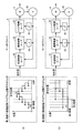
- FIG. 7 and 8 are diagrams for explaining the coordinate conversion according to the embodiment of the present invention.
- a machine coordinate system (XYZ coordinate system) with reference to the workpiece W shown in FIG. 6 and an axis coordinate system for each rotation angle of the servo motors 4-1, 4-2, 4-3 ( ( ⁇ 1- ⁇ 2- ⁇ 3 coordinate system).
- Fig. 7 consider a combination of two linear motions in the machine coordinate system. That is, the linear movement from the first start position (Xs1, Ys1, Zs1) to the first target position (Xe1, Ye1, Ze1), and the first target position (Xe2) from the second start position (Xs2, Ys2, Zs2). , Ye2, Ze2).
- the first target position (Xe1, Ye1, Ze1) and the second start position (Xs2, Ys2, Zs2) are the same.
- the temporal change in displacement at each coordinate in the machine coordinate system is as shown in FIG. That is, in each of the X-axis, Y-axis, and Z-axis, the coordinate position in each section changes primarily with respect to the time axis from a value corresponding to the start position to a value corresponding to the target position.
- each of the rotation angles ⁇ 1, ⁇ 2, and ⁇ 3 changes nonlinearly with respect to the time axis. .
- Such correspondence between the machine coordinate system and the axis coordinate system is expressed as follows using the position (X, Y, Z) in the machine coordinate system and the position ( ⁇ 1, ⁇ 2, ⁇ 3) in the axis coordinate system. It can be shown as follows.
- X f 1 ( ⁇ 1) + f 1 ( ⁇ 2) + f 1 ( ⁇ 3)
- Y f 2 ( ⁇ 1) + f 2 ( ⁇ 2) + f 2 ( ⁇ 3)
- Z f 3 ( ⁇ 1) + f 3 ( ⁇ 2) + f 3 ( ⁇ 3)
- ⁇ 1 g 1 (X) + g 1 (Y) + g 1 (Z)
- ⁇ 2 g 2 (Y) + g 2 (Y) + g 2 (Z)
- ⁇ 3 g 3 (Z) + g 3 (Z) + g 3 (Z) + g 3 (Z)
- the displacement amount of each servo motor 4 needs to be integrally controlled. Basically, it is not appropriate to drive only a specific axis alone.
- the PLC 1 provides a function for easily managing a plurality of servo motors related to the same motion operation and a user interface related thereto.
- FIG. 9 is a flowchart showing a control procedure related to motion control of PLC 1 according to the embodiment of the present invention.
- FIG. 9 shows a case where the calculation for calculating the motion control command value is executed in the first control cycle, and the process of changing the final target value is executed in the second control cycle.
- the microprocessor 100 of the CPU unit 13 of the PLC 1 executes an initial process (step S2).
- This initial processing includes setting of initial parameters, calculation of initial values, updating of network connection destinations, and the like.
- information about servo motor drivers 3 corresponding to a plurality of servo motors 4 involved in the same motion operation is acquired.
- the fact that a plurality of servo motors 4 are involved in the same motion control is also referred to as “belonging to an axis group”.
- step S4 the microprocessor 100 executes a device control process.
- This device control processing includes processing for setting a final target position in the machine coordinate system in accordance with various information (state values) obtained from the device to be controlled.
- step S6 the microprocessor 100 acquires a target position related to motion control (step S6). That is, the microprocessor 100 sequentially calculates the final target position (Xe, Ye, Ze) in the coordinate system (machine coordinate system) related to the same motion operation.
- the microprocessor 100 compares the current position with the acquired final target position, and determines whether or not the control target has reached the target position (step S8). If the control target has reached the final target position (YES in step S8), the second control cycle is advanced from the current cycle N to the next cycle N + 1 (step S10), and the processing from step S4 is executed again. Is done.
- the microprocessor 100 sets the target in the first coordinate system (machine coordinate system) in the current cycle n of the first control period.
- the position is calculated (step S12).
- the target position is calculated based on a process of calculating a trajectory from the current position to the final target position acquired in step S6 according to a rule (for example, an interpolation method) specified in advance, and based on the calculated trajectory. This includes processing for calculating a position (target position) to be moved in the current cycle n of one control cycle.
- the microprocessor 100 calculates a target position in the second coordinate system (axis coordinate system) corresponding to the target position acquired in Step S12 using a predetermined coordinate conversion function (Step S14). Subsequently, the microprocessor 100 determines, based on the deviation between the target position in the second coordinate system (axis coordinate system) and the current position in the second coordinate system in the current cycle n of the first control period, in the current control period. The amount ( ⁇ 1, ⁇ 2, ⁇ 3) to be moved for each axis is calculated (step S16). This amount to be moved becomes a command value for each servo motor driver.
- the microprocessor 100 monitors the states of the movements of the servo motors 4 belonging to the same axis group, and determines whether any of the movements of the servo motors 4 is abnormal (step). S18).
- step S18 If an abnormality occurs in any of the movements of the servo motor 4 (YES in step S18), the microprocessor 100 stops all the servo motors 4 belonging to the same axis group (step S20). Details of this stopping method will be described later.
- microprocessor 100 calculates in step S12 the command values for servo motors 4 belonging to the same axis group all at once. Output (step S22).
- step S24 After the first control cycle is advanced from the current cycle n to the next cycle n + 1 (step S24), the processing after step S12 is executed again.
- FIG. 10 is a functional block diagram relating to motion control of the PLC 1 according to the embodiment of the present invention.
- Each functional module shown in FIG. 10 is basically provided by the microprocessor 100 executing a control program 230 (typically an object format program).
- the CPU unit 13 has, as its control functions, a device control module 402, a coordinate conversion module 404, command value calculation / state management modules 406-1, 406-2,. And “monitoring module 410”.
- the device control module 402 sequentially calculates the final target position in the machine coordinate system in accordance with various information (state values) obtained from the device to be controlled.
- the sequentially calculated final target position of the machine coordinate system is given to the coordinate conversion module 404. That is, the apparatus control module 402 sequentially calculates the first target position in the first coordinate system related to the same motion operation.
- the coordinate conversion module 404 acquires the final target position from the apparatus control module 402, and calculates a trajectory from the current position to the final target position according to a rule specified in advance. Then, the coordinate conversion module 404 acquires a target position in the machine coordinate system in the current control cycle. Further, the coordinate conversion module 404 sequentially calculates a target position in the second coordinate system (axis coordinate system) corresponding to the target position in the machine coordinate system in accordance with a predetermined correspondence (conversion function).
- the second coordinate system (axis coordinate system) is defined by a plurality of axes ( ⁇ 1, ⁇ 2, ⁇ 3) respectively associated with the plurality of servo motors 4 involved in the same motion operation.
- the sequentially calculated target positions are output to the command value calculation / state management modules 406-1, 406-2, ..., 406-n. Note that only the component of the target position on the corresponding axis may be output to each of the command value calculation / state management module 406. That is, only the first axis component ( ⁇ 1) is output to the command value calculation / state management module 406-1 corresponding to the first axis.
- Each of the command value calculation / state management module 406 calculates a motion command value for the corresponding servo motor driver 3 (drive device) for each control cycle of motion control.
- Each of the command value calculation / status management modules 406 outputs the motion command value to the corresponding servo motor driver 3 for each control cycle at substantially the same timing as the other command value calculation / status management modules 406.
- the command value given to the servo motor driver 3 generally uses a number of pulses corresponding to the movement amount (displacement amount) from the current position.
- the servo motor driver 3 rotates the servo motor 4 by an angle corresponding to the number of pulses included in the command value.
- the coordinate conversion module 404 and the command value calculation / state management modules 406-1, 406-2,..., 406-n serve as target position calculation means and command value calculation means according to the present invention. Realize.
- the monitoring module 410 monitors the state of each of the plurality of servo motors 4 and responds to the occurrence of an abnormality in one of the plurality of servo motors 4 at the same time. To stop. More specifically, the monitoring module 410 acquires the status values of the respective servo motors 4 and servo motor drivers 3 via the command value calculation / status management module 406, and detects an abnormality based on the acquired status values. Judgment is made. As this abnormality, for example, the actual value (displacement feedback value) is not sufficiently obtained for the output command value, or an error due to an overcurrent has occurred in the servo motor driver 3. Including.
- FIG. 11 is a diagram for explaining tasks executed by the CPU unit 13 of the PLC 1 according to the embodiment of the present invention.
- FIG. 11A shows a case where a process related to motion control (first control period) and a process related to coordinate transformation (second control period) are both executed in a common control period.
- FIG. 11B shows a case where the control cycle of the process related to coordinate transformation is set to an integral multiple of the control cycle of the process related to motion control (twice in the example shown in FIG. 11B). .
- each of control cycles 1 to 4 represents a control cycle related to motion control.
- the control cycle (first control cycle) related to the motion control indicates a cycle in which a new command value is output to the servo motor driver 3 (the command value is updated). That is, in the servo motor driver 3, a new command value is given for each period corresponding to one control cycle.
- a function for converting a target position in a machine coordinate system to a target position in an axis coordinate system includes a nonlinear element such as a trigonometric function. For this reason, the process for calculating the target position of the axis coordinate system (that is, the coordinate conversion process) requires a large amount of calculation and requires a relatively long calculation time. Therefore, a task for determining the target position may be set as a task different from the process of calculating and outputting the command value to the servo motor driver 3.
- tasks related to motion control include O / I (Output / Input) processing, command value calculation processing (calculation of all command values belonging to the same axis group), and state monitoring processing.
- the task for determining the target position includes apparatus control processing and coordinate conversion processing.
- the task for determining the target position is repeatedly executed at every control cycle of motion control, and a machine coordinate system is generated using a process for generating a final target position and a function registered in advance. And converting the target position in to a target position in the axis coordinate system.
- Tasks related to motion control are repeatedly executed at every control cycle of motion control.
- each motion command value is calculated from the deviation between the current position and the target position in the axis coordinates.
- the task for determining the target position is repeatedly executed in the same control cycle as the task related to motion control. Therefore, the target position in the axis coordinate system calculated in each control cycle is executed in the next control cycle.
- the target position in the machine coordinate system is converted and the target position in the axis coordinate system is sequentially calculated, and the motion control is performed while minimizing the time delay from the target position conversion process. be able to.
- the example shown in FIG. 11B is more suitable when the amount of calculation related to coordinate conversion is relatively large.
- the task of determining the target position is executed repeatedly every cycle that is an integral multiple of the control cycle of motion control, and is determined along the trajectory from the current position to the final target position. Is converted into a target position in the axis coordinate system using a previously registered function.
- FIG. 12 is a diagram for explaining the control responsiveness accompanying the change in the control cycle shown in FIG.
- FIG. 12A shows a processing example in the case where the task for determining the target position is repeatedly executed at the same control cycle as the task related to motion control, corresponding to FIG. 11A.
- FIG. 12B shows an example of processing in the case where the task for determining the target position is repeatedly executed every cycle that is an integral multiple of the control cycle of motion control, corresponding to FIG. 11B. .
- the servo motor driver 3 employs an open loop type, and when viewed from the CPU unit 13 of the PLC 1, if a command value is given, the subsequent control is performed. Is executed in the servo motor driver 3. More specifically, the servo motor driver 3 includes a position control loop 31, a speed control loop 32, a torque control loop 33, a primary differentiator 34, and a secondary differentiator 35. Using these loop controls, torque control, speed control, and position control are performed using a given command value (target position) and a feedback actual value (position pulse).
- the command value is output in the control cycle next to the completion of the calculation of the target position in the axis coordinate system, and higher responsiveness can be realized.
- the command value is updated at each control period of the task related to coordinate conversion. Therefore, the responsiveness is slightly lowered as compared with the case of FIG.
- the CPU unit 13 executes target position interpolation processing in the command value calculation processing included in the task related to motion control. That is, the command value calculation process is repeatedly executed at every control cycle of motion control, and each motion command value is calculated from the deviation between the current position and the target position in the axis coordinate system. At this time, in the command value calculation process, each motion command value is calculated for each control cycle of the motion control by interpolating between the current position and the target position in the axis coordinate system.
- the target position correction method various known methods can be adopted. However, as the simplest method, the current position and the target position in the axis coordinate system are linearly interpolated and then the linear interpolation is performed. A method can be employed in which the midpoint of the trajectory obtained by the above is set as the target position in the first control cycle, and the given target position is set as the target position in the second control cycle.
- FIG. 11 described above shows an example in which two tasks can be executed independently in order to facilitate understanding.
- a configuration can be easily realized by adopting a multi-core processor having a plurality of cores as the microprocessor 100.
- priorities are determined in advance between tasks, and tasks with lower priorities are executed primarily during the period when tasks with higher priorities are executed. Task switching such as stopping at a later time may be performed.
- the control cycle of the coordinate conversion process can be set to an integral multiple of the control cycle of motion control. Even in such a case, the control accuracy of the motion control can be maintained by performing the interpolation processing of the target position as described above.
- the control program as described above is created by the PLC support device 8. That is, the PLC support device 8 corresponds to a support device for creating a program executed by the CPU unit 13 of the PLC 1 capable of motion control.
- FIG. 13 is a schematic diagram for explaining generation of the control program 230 executed by the PLC 1 according to the embodiment of the present invention.
- control program 230 according to the present embodiment includes device control program code 452, coordinate conversion program code 454, servo driver mapping information 472, group definition information 474, and library group 460. Generated.
- the device control program code 452 is a source code in which a program for controlling a control target is described. Sequence control logic for generating output data in accordance with whether or not a predetermined condition is satisfied for input data, , Including a logic for calculating and outputting a target position of the movement destination of the robot on condition that a predetermined condition is satisfied.
- the user operates a GUI (Graphical User Interface) provided by an editor program 321 (FIG. 5) executed on the PLC support device 8 to create a user program corresponding to the control target.
- the PLC support device 8 has a function of receiving a command for sequentially calculating the target position in the machine coordinate system related to the same motion operation.
- the coordinate conversion program code 454 includes source code and various settings for converting the target position of the machine coordinate system as described above into the target position of the axis coordinate system.
- a group of servo motor drivers 3 (and corresponding servo motors 4) belonging to the same axis group, which is a target of coordinate conversion, is designated. This designation method will be described later.
- the servo driver mapping information 472 is an address (identification information) on the bus and / or a field network when the servo motor driver 3 is connected to the CPU unit 13 via the PLC system bus 11 and / or the field network 2.
- 2 is information that defines each servo motor driver 3 in association with an address (identification information) 2.
- the group definition information 474 is information for defining the servo motor driver 3 (and corresponding servo motor 4) belonging to the same axis group.
- the servo motor driver 3 (and corresponding servo motor 4) belonging to each axis group is identified using the identification information (name) of the servo motor driver 3 defined in the servo driver mapping information 472. It is specified.
- the library group 460 is a data group including libraries, subroutines, modules, and the like necessary for generating the control program 230.
- the control program 230 is generated by incorporating some or all of the data during compilation.
- the library group 460 includes modules for basic functions provided by the CPU unit 13 according to the present embodiment, in addition to modules for realizing functions called in the device control program code 452. More specifically, the library group 460 includes data for realizing the monitoring module 410 shown in FIG.
- control program 230 in the object program format will be described, but the same applies to the case of using a control program in the mnemonic format or a similar format.
- functional modules corresponding to the library group 460 are built into the CPU unit 13 in the form of firmware or hardware.
- the compiler program 322 is executed by the PLC support device 8, so that the compilation process is executed and the control program 230 is generated. That is, the PLC support device 8 has a function of generating the control program 230 from the various input information as described above.
- FIG. 14 is a diagram showing an example of the device control program code 452 shown in FIG.
- FIG. 14 shows an example in which a coordinate conversion program is realized using a function block defined by IEC61131-3 as an example. That is, FIG. 14 shows a description example using a ladder language generally used in PLC.
- the contact 1 becomes TRUE (on)
- the input final target position Xe, Ye, Ze
- the input final target position Xe, Ye, Ze
- the user can define a function to be used for the coordinate transformation by tapping the coordinate transformation function block on an editor screen or the like displayed on the PLC support device 8.
- the PLC support device 8 accepts a correspondence (coordinate conversion function) for calculating the target position in the axis coordinate system corresponding to the target position in the machine coordinate system.
- the axis coordinate system is defined by a plurality of axes respectively associated with a plurality of servo motors 4 involved in the same motion operation.
- the user can set an arbitrary method (such as an interpolation method) for calculating a trajectory from the current position of the machine coordinate system to the final target position in the PLC support device 8.
- an arbitrary method such as an interpolation method
- the trajectory determination method for the final target value of the machine coordinate system, and the conversion function from the target position of the machine coordinate system to the target position of the corresponding axis coordinate system. Can be arbitrarily set by the user. Therefore, unlike the conventional case, there is no need for a dedicated motion controller to hold information such as a conversion function.
- FIG. 15 is a diagram showing an example of a user interface screen 500 for setting the group definition information 474 shown in FIG.
- user interface screen 500 is provided by PLC support device 8.
- an input box 502 for selecting an axis group number an input box 504 for selecting whether to enable / disable the axis group function, and an input box 506 for inputting the number of axes included in the axis group are selected.
- FIG. 15 shows a situation where the axis group “0” is selected. Subsequently, in order to validate the axis group function, the user selects “Using Group” in the input box 504 (which means that the axis group is used). Further, the user inputs the number of axes belonging to the selected axis group in the input box 506. The example shown in FIG. 15 shows an example in which “2” axes are selected.
- the PLC support device 8 displays an image 508 of the device corresponding to the number of input axes according to the number of axes input to the input box 506.
- the example shown in FIG. 16 shows an example in which a device that moves in two directions is conceptually displayed.
- the user designates the servo motor driver 3 belonging to the selected axis group in the input list 510.
- an axis group including two axes is set, and “MC_Axis000 (0)” and “MC_Axis000 (1)” are designated as the servo motor driver 3 belonging to this axis group.
- the PLC support device 8 has a function of receiving designation of servo motor drivers 3 (drive devices) corresponding to a plurality of servo motors 4 involved in the same motion operation.
- This designated information is stored as group definition information 474 (FIG. 13).
- Information (group definition information 474) for designating the servo motor driver 3 (driving device) corresponding to the plurality of servo motors 4 involved in the same motion operation is incorporated into the control program 230, and substantially CPU It is stored in the unit 13.
- the group definition information 474 may be stored in the memory of the CPU unit 13 as it is. In this way, the servo motor driver 3 belonging to the same axis group can be changed more easily.
- the PLC support device 8 can appropriately select a stopping method in such a simultaneous stop according to the application to which the application is applied.
- the method of stopping a plurality of servo motors 4 at a time can basically be arbitrarily selected from the following three methods.
- a method for simultaneously setting each motion command value corresponding to a plurality of servo motors to zero (2) A method for stopping a plurality of servo motors independently from each other at a deceleration acceleration allowed for the corresponding axis (3) ) A method to reduce the speed while maintaining the trajectory determined from the relationship between the current position and the target position of the machine coordinate system. Furthermore, the processing to reset the deviation in the control logic and the servo motor at the time of deceleration Processing for invalidating the monitoring of the acceleration / jerk 4 may be further added.
- FIG. 16 is a diagram showing an example of a user interface screen 600 for designating a stop method provided by the PLC support device 8 according to the embodiment of the present invention.
- FIG. 17 is a diagram for explaining a stop operation corresponding to each mode selected in FIG.
- modes 601 to 604 correspond to any one of the above-described stop operations (1) to (3).
- FIG. 17A shows the stop operation when any one of these modes is selected. That is, as shown in FIG. 17A, if an abnormality occurs in any one of the servo motor drivers 3 (and corresponding servo motors 4), the other servo motor drivers 3 (and The command values including the corresponding servo motors 4) are simultaneously changed to “0”.
- the above-described method (2) in which a plurality of servo motors are stopped independently of each other with the deceleration acceleration allowed on the corresponding axis, corresponds to mode 602.
- the stop operation when this mode is selected is shown in FIG. That is, as shown in FIG. 17B, if an abnormality occurs in any one of the servo motor drivers 3 (and corresponding servo motors 4), the respective servo motor drivers 3 (and The corresponding servo motor 4) has its command value reduced to “0” in accordance with the allowable deceleration acceleration ⁇ 1 to ⁇ 3.
- the timing at which the command value actually becomes “0” may be different depending on the magnitude (absolute value) of each command value and the maximum deceleration acceleration.
- this method can stop the operation most quickly while reducing the possibility of mechanical breakage in each axis.
- the above-described (3) method of reducing the speed while maintaining the trajectory determined from the relationship between the current position and the target position of the machine coordinate system corresponds to mode 601.
- the stop operation when this mode is selected is shown in FIG. That is, as shown in FIG. 17C, if an abnormality occurs in any of the servo motor drivers 3 (and corresponding servo motors 4), each servo motor driver 3 (and The corresponding servo motor 4) reduces the overall speed to "0" while keeping the planned trajectory. In this case, since the planned trajectory can be observed even during the stop operation, it can be stopped more safely.
- the CPU unit 13 is a controller (motion controller) capable of controlling a mechanical device that needs to perform coordinate conversion between an axis coordinate system of the servo motor and a machine coordinate system of the mechanical mechanism. .
- the CPU unit 13 can realize an operation method that realizes a desired operation by giving a target position to each of a plurality of axes in each control cycle by a user program. At the same time, the CPU unit 13 provides a function for collectively monitoring abnormalities on these multiple axes, so that it is necessary to remodel the motion controller one by one when adding a coordinate conversion formula according to the mechanical mechanism. There is no. Furthermore, the user does not need to monitor the axis state individually for each axis.
- the CPU unit 13 is a motion controller that controls a mechanical device that needs to perform coordinate conversion between the axis coordinate system of the servo motor and the coordinate system of the mechanical mechanism.
- the user can create a coordinate conversion program for converting the coordinates of the mechanical mechanism into the axis coordinates of the motor.
- This coordinate conversion program can give independent target positions for at least two axes in each control cycle, and command the command value to reach the target position in the next control cycle to the motor driver for each axis. It has the function to do.
- the CPU unit 13 repeats the program for calculating the command value for each axis for each first fixed period, and repeats the coordinate conversion program for each first fixed period.
- the CPU unit 13 repeats the program for calculating the command value for each axis for each first fixed period, and the second standard conversion program is an integer multiple of the first fixed period. It can also be repeated at regular intervals.
- the CPU unit 13 according to the present embodiment has a function of stopping the operation of the remaining axes when at least one of the axes to be operated simultaneously becomes abnormal. Furthermore, the CPU unit 13 according to the present embodiment can be stopped so as to keep the target trajectory, stop at the maximum current speed of each axis, stop immediately, or immediately stop and deviation. It has a function that allows the user to specify whether to perform reset processing or stop and stop the servo feedback of the axis.
- any axis belonging to the same axis group has an abnormality, it can be stopped including other axes.
- an error occurs in these multiple axes. It is possible to solve the conventional problem that it is complicated because it is necessary to implement in the user program whether or not the problem has occurred and how to stop it when it occurs.
- the trajectory determination method for the final target value of the machine coordinate system and the conversion function from the target position of the machine coordinate system to the target position of the corresponding axis coordinate system Can be set arbitrarily. Therefore, unlike the conventional case, there is no need for a dedicated motion controller to hold information such as a conversion function. Even when new mechanical mechanisms are introduced, the user can easily set the trajectory interpolation method and coordinate conversion function corresponding to the mechanical mechanism, so it is possible to handle these new mechanical mechanisms without cost and effort. it can.
Abstract
演算ユニットは、同一のモーション動作に係る、第1の座標系における第1の目標位置を順次算出する目標位置算出手段と、予め定められた対応関係に従って、第1の目標位置に対応する第2の座標系における第2の目標位置を順次算出することで、指定された駆動装置に対するそれぞれのモーション指令値を、モーション制御の制御周期毎に算出する指令値算出手段とを含む。ここで、第2の座標系は、同一のモーション動作に関与する複数のモータにそれぞれ関連付けられた複数の軸で定義される。演算ユニットは、さらに、モーション制御の制御周期毎に、複数のモータに対するそれぞれのモーション指令値を一斉に出力する出力手段を含む。
Description
本発明は、モーション制御が可能なコントローラの演算ユニット、ならびに、それに向けられた支援装置、その支援装置を実現するための支援プログラム、その支援プログラムを格納した記憶媒体、および、その支援装置における動作方法に関する。
プログラマブルロジックコントローラ(Programmable Logic Controller:以下「PLC」と称す。)は、たとえば、ユーザプログラムを実行する演算ユニット、外部のスイッチやセンサからの信号入力および外部のリレーやアクチュエータへの信号出力を担当するIO(Input Output)ユニットといった複数のユニットで構成される。それらのユニット間で、ユーザプログラム実行サイクルごとに、PLCシステムバスおよび/またはフィールドネットワークを経由してデータの授受をしながら、PLCは制御動作を実行する。
機械、設備などの動作の制御としては、モータの運動を制御するためのモーション制御が含まれる場合がある。このようなモーション制御の典型例としては、位置決めテーブルやロボットといったメカニカル機構の位置決めを行うようなアプリケーションが想定される。このようなアプリケーションでは、単一のメカニカル機構を複数のモータ(複数の軸)で構成しているような場合が多い。このような複数のモータ(複数の軸)を管理する方法として、非特許文献1では、座標変換や状態管理を行う単位として「軸グループ」を定義することが提案されている。
なお、上述のようなメカニカル機構を駆動するモーションコントローラでは、モータの座標系(例えば、関節座標系など)と、メカニカル機構が有する座標系(例えば、機械座標系、ツール座標系、エンドエフェクタ座標系など)との間の幾何学的関係を表した座標変換式を用いて、メカニカル機構を所望の軌道で動作させるために必要なそれぞれのモータへの指令値をそれぞれ算出する必要があった。
Technical Specification PLCopen - Technical Committee 2 - Task Force,Function blocks for motion control(Formerly Part 1 and Part 2),PLCopen Working Draft,Version 1.99 - Release for comments - till August 16, 2010
上述の非特許文献1では、軸グループを有効にするファンクションブロック、および、軸グループを無効にするファンクションブロックについて言及されており、これらのファンクションブロックを用いて、例えば直線補間を行う場合には、以下のような処理を用いて実現されることが開示されている。すなわち、軸グループを有効化する、軸グループの間で直線補間を行う、軸グループを無効化する。
非特許文献1では、このように軸グループが有効化されている期間中に可能な動作として、補間動作やギア動作などが例示されている。非特許文献1では、さらに、メカニカル機構とモータとの間の座標変換式をモーションコントローラが持つことを要求している。しかし、汎用モーションコントローラではあらゆるメカニカル機構に対応する座標変換式を用意することは不可能である。そのため、新しいメカニカル機構が導入されるたびに、新しい座標変換式を追加するためにモーションコントローラを改造しなければならず、時間およびコストの面で不利であった。
本願発明は上記の問題点に鑑みなされたものであって、その目的は、複数の軸のモータからなる単一のメカニカル機構に対して、モーション制御を容易に実現できる演算ユニット、ならびに、それに向けられた支援装置および支援プログラムを提供することである。
本発明のある局面に従えば、モーション制御が可能なコントローラの演算ユニットを提供する。演算ユニットは、複数のモータを制御するための、1つ以上の駆動装置と通信するためのインターフェイスと、同一のモーション動作に関与する複数のモータに対応する駆動装置を指定するための情報を格納する記憶手段と、同一のモーション動作に係る、第1の座標系における第1の目標位置を順次算出する目標位置算出手段と、予め定められた対応関係に従って、第1の目標位置に対応する第2の座標系における第2の目標位置を順次算出することで、指定された駆動装置に対するそれぞれのモーション指令値を、モーション制御の制御周期毎に算出する指令値算出手段とを含む。ここで、第2の座標系は、同一のモーション動作に関与する複数のモータにそれぞれ関連付けられた複数の軸で定義される。演算ユニットは、さらに、モーション制御の制御周期毎に、複数のモータに対するそれぞれのモーション指令値を一斉に出力する出力手段を含む。
好ましくは、目標位置算出手段は、最終目標位置を取得する手段と、予め指定された規則に従って現在位置から最終目標位置までの軌道を算出する手段とを含む。
好ましくは、演算ユニットは、複数のモータの運動についての状態をそれぞれ監視するとともに、複数のモータの運動のうちいずれかに異常が発生したことに応答して、複数のモータを一斉に停止させる監視手段をさらに含む。
さらに好ましくは、複数のモータの運動を一斉に停止させる方式は、現在位置と第1の目標位置との関係から決定される軌道を維持しつつ、速度を低下させる方式、対応する軸において許容される減速加速度で、複数のモータを互いに独立してそれぞれ停止させる方式、および、複数のモータに対応するそれぞれのモーション指令値を一斉にゼロにする方式のうち、いずれか1つである。
好ましくは、指令値算出手段は、モーション制御の制御周期毎に繰返し実行される、第1の目標位置を第2の目標位置に変換する座標変換処理と、モーション制御の制御周期毎に繰返し実行される、現在位置と第2の目標位置との偏差からそれぞれのモーション指令値を算出する指令値算出処理とを含む。
好ましくは、指令値算出手段は、モーション制御の制御周期の整数倍である周期毎に繰返し実行される、第1の目標位置を第2の目標位置に変換する座標変換処理と、モーション制御の制御周期毎に繰返し実行される、現在位置と第2の目標位置との偏差からそれぞれのモーション指令値を算出する指令値算出処理とを含み、指令値算出処理では、現在位置と第2の目標位置との間を補間することで、モーション制御の制御周期毎にそれぞれのモーション指令値が算出される。
この発明の別の局面に従えば、モーション制御が可能なコントローラの演算ユニットで実行されるプログラムを作成するための支援装置を提供する。支援装置は、同一のモーション動作に関与する複数のモータに対応する駆動装置の指定を受け付ける指定手段と、同一のモーション動作に係る、第1の座標系における第1の目標位置を順次算出するための命令を受け付ける命令入力手段と、第1の目標位置に対応する第2の座標系における第2の目標位置を算出するための対応関係を受け付ける対応関係入力手段とを含む。ここで、第2の座標系は、同一のモーション動作に関与する複数のモータにそれぞれ関連付けられた複数の軸で定義される。支援装置は、さらに、入力された情報からプログラムを生成する生成手段を含む。演算ユニットは、複数のモータを制御するための、1つ以上の駆動装置と通信するように構成されており、プログラムを実行することで、第1の目標位置に対応する第2の目標位置を順次算出することで、指定された駆動装置に対するそれぞれのモーション指令値を算出するとともに、モーション制御の制御周期毎に、複数のモータに対するそれぞれのモーション指令値を一斉に出力する。
この発明のさらに別の局面に従えば、モーション制御が可能なコントローラの演算ユニットで実行されるプログラムを作成するための支援プログラムを提供する。支援プログラムは、コンピュータを、同一のモーション動作に関与する複数のモータに対応する駆動装置の指定を受け付ける指定手段と、同一のモーション動作に係る、第1の座標系における第1の目標位置を順次算出するための命令を受け付ける命令入力手段と、第1の目標位置に対応する第2の座標系における第2の目標位置を算出するための対応関係を受け付ける対応関係入力手段として機能させる。ここで、第2の座標系は、同一のモーション動作に関与する複数のモータにそれぞれ関連付けられた複数の軸で定義される。支援プログラムは、さらに、入力された情報からプログラムを生成する生成手段として機能させる。演算ユニットは、複数のモータを制御するための、1つ以上の駆動装置と通信するように構成されており、プログラムを実行することで、第1の目標位置に対応する第2の目標位置を順次算出することで、指定された駆動装置に対するそれぞれのモーション指令値を算出するとともに、モーション制御の制御周期毎に、複数のモータに対するそれぞれのモーション指令値を一斉に出力する。
この発明のさらに別の局面に従えば、モーション制御が可能なコントローラの演算ユニットで実行されるプログラムを作成するための支援プログラムを格納する記憶媒体を提供する。支援プログラムは、コンピュータを、同一のモーション動作に関与する複数のモータに対応する駆動装置の指定を受け付ける指定手段と、同一のモーション動作に係る、第1の座標系における第1の目標位置を順次算出するための命令を受け付ける命令入力手段と、第1の目標位置に対応する第2の座標系における第2の目標位置を算出するための対応関係を受け付ける対応関係入力手段として機能させる。ここで、第2の座標系は、同一のモーション動作に関与する複数のモータにそれぞれ関連付けられた複数の軸で定義される。支援プログラムは、さらに、入力された情報からプログラムを生成する生成手段として機能させる。演算ユニットは、複数のモータを制御するための、1つ以上の駆動装置と通信するように構成されており、プログラムを実行することで、第1の目標位置に対応する第2の目標位置を順次算出することで、指定された駆動装置に対するそれぞれのモーション指令値を算出するとともに、モーション制御の制御周期毎に、複数のモータに対するそれぞれのモーション指令値を一斉に出力する。
この発明のさらに別の局面に従えば、モーション制御が可能なコントローラの演算ユニットで実行されるプログラムを作成するための支援装置における動作方法を提供する。動作方法は、同一のモーション動作に関与する複数のモータに対応する駆動装置の指定を受け付けるステップと、同一のモーション動作に係る、第1の座標系における第1の目標位置を順次算出するための命令を受け付けるステップと、第1の目標位置に対応する第2の座標系における第2の目標位置を算出するための対応関係を受け付けるステップとを含む。ここで、第2の座標系は、同一のモーション動作に関与する複数のモータにそれぞれ関連付けられた複数の軸で定義される。動作方法は、さらに、入力された情報からプログラムを生成するステップを含む。演算ユニットは、複数のモータを制御するための、1つ以上の駆動装置と通信するように構成されており、プログラムを実行することで、第1の目標位置に対応する第2の目標位置を順次算出することで、指定された駆動装置に対するそれぞれのモーション指令値を算出するとともに、モーション制御の制御周期毎に、複数のモータに対するそれぞれのモーション指令値を一斉に出力する。
本発明によれば、複数の軸のモータからなる単一のメカニカル機構に対して、モーション制御を容易に設定および監視できる。
本発明の実施の形態について、図面を参照しながら詳細に説明する。なお、図中の同一または相当部分については、同一符号を付してその説明は繰返さない。
<A.システム構成>
本実施の形態に係るPLCは、モータの運動を制御するためのモーション制御機能を有する。まず、図1を参照して、本実施の形態に係るPLC1のシステム構成について説明する。
本実施の形態に係るPLCは、モータの運動を制御するためのモーション制御機能を有する。まず、図1を参照して、本実施の形態に係るPLC1のシステム構成について説明する。
図1は、本発明の実施の形態に係るPLCシステムの概略構成を示す模式図である。図1を参照して、PLCシステムSYSは、PLC1と、PLC1とフィールドネットワーク2を介して接続されるサーボモータドライバ3-1,3-2,…,3-n(以下「サーボモータドライバ3」とも総称する。)およびリモートIOターミナル5と、フィールド機器である検出スイッチ6およびリレー7とを含む。また、PLC1には、接続ケーブル10などを介してPLCサポート装置8が接続される。
PLC1は、主たる演算処理を実行するCPUユニット13と、1つ以上のIOユニット14と、特殊ユニット15とを含む。これらのユニットは、PLCシステムバス11を介して、データを互いに遣り取りできるように構成される。また、これらのユニットには、電源ユニット12によって適切な電圧の電源が供給される。なお、PLC1として構成される各ユニットは、PLCメーカーが提供するものであるので、PLCシステムバス11は、一般にPLCメーカーごとに独自に開発され、使用されている。これに対して、後述するようにフィールドネットワーク2については、異なるメーカーの製品同士が接続できるように、その規格などが公開されている場合も多い。
PLC1の演算ユニットであるCPUユニット13の詳細については、図2を参照して後述する。
IOユニット14は、一般的な入出力処理に関するユニットであり、オン/オフといった2値化されたデータの入出力を司る。すなわち、IOユニット14は、検出スイッチ6などのセンサが何らかの対象物を検出している状態(オン)および何らの対象物も検出していない状態(オフ)のいずれであるかという情報を収集する。また、IOユニット14は、リレー7やアクチュエータといった出力先に対して、活性化するための指令(オン)および不活性化するための指令(オフ)のいずれかを出力する。
特殊ユニット15は、アナログデータの入出力、温度制御、特定の通信方式による通信といった、IOユニット14ではサポートしない機能を有する。
フィールドネットワーク2は、CPUユニット13と遣り取りされる各種データを伝送する。フィールドネットワーク2としては、典型的には、各種の産業用イーサネット(登録商標)を用いることができる。産業用イーサネット(登録商標)としては、たとえば、EtherCAT(登録商標)、Profinet IRT、MECHATROLINK(登録商標)-III、Powerlink、SERCOS(登録商標)-III、CIP Motionなどが知られており、これらのうちのいずれを採用してもよい。さらに、産業用イーサネット(登録商標)以外のフィールドネットワークを用いてもよい。たとえば、モーション制御を行わない場合であれば、DeviceNet、CompoNet/IP(登録商標)などを用いてもよい。本実施の形態に係るPLCシステムSYSでは、典型的に、本実施の形態においては、産業用イーサネット(登録商標)であるEtherCAT(登録商標)をフィールドネットワーク2として採用する場合の構成について例示する。
なお、図1には、PLCシステムバス11およびフィールドネットワーク2の両方を有するPLCシステムSYSを例示するが、一方のみを搭載するシステム構成を採用することもできる。たとえば、フィールドネットワーク2ですべてのユニットを接続してもよい。あるいは、フィールドネットワーク2を使用せずに、サーボモータドライバ3をPLCシステムバス11に直接接続してもよい。さらに、フィールドネットワーク2の通信ユニットをPLCシステムバス11に接続し、CPUユニット13から当該通信ユニット経由で、フィールドネットワーク2に接続された機器との間の通信を行うようにしてもよい。
サーボモータドライバ3-1,3-2,…,3-nは、フィールドネットワーク2を介してCPUユニット13と接続されるとともに、CPUユニット13からの指令値に従ってサーボモータ4-1,4-2,…,4-n(以下「サーボモータ4」とも総称する。)をそれぞれ駆動する。サーボモータドライバ3は、モータを制御するための駆動装置に相当する。より具体的には、サーボモータドライバ3は、PLC1から一定周期で、位置指令値、速度指令値、トルク指令値といった指令値を受ける。また、サーボモータドライバ3は、サーボモータ4の軸に接続されている位置センサ(ロータリーエンコーダ)やトルクセンサといった検出器から、位置、速度(典型的には、今回位置と前回位置との差から算出される)、トルクといったサーボモータ4の動作に係る実測値を取得する。そして、サーボモータドライバ3は、CPUユニット13からの指令値を目標位置に設定し、実測値をフィードバック値として、フィードバック制御を行う。すなわち、サーボモータドライバ3は、実測値が目標位置に近づくようにサーボモータ4を駆動するための電流を調整する。なお、サーボモータドライバ3は、サーボモータアンプと称されることもある。
また、図1には、サーボモータ4とサーボモータドライバ3とを組み合わせたシステム例を示すが、その他の構成、たとえば、パルスモータとパルスモータドライバとを組み合わせたシステムを採用することもできる。
図1に示すPLCシステムSYSのフィールドネットワーク2には、さらに、リモートIOターミナル5が接続されている。リモートIOターミナル5は、基本的には、IOユニット14と同様に、一般的な入出力処理に関する処理を行う。より具体的には、リモートIOターミナル5は、フィールドネットワーク2でのデータ伝送に係る処理を行うための通信カプラ52と、1つ以上のIOユニット53とを含む。これらのユニットは、リモートIOターミナルバス51を介して、データを互いに遣り取りできるように構成される。
なお、PLCサポート装置8については後述する。
<B.CPUユニットのハードウェア構成>
次に、図2を参照して、CPUユニット13のハードウェア構成について説明する。図2は、本発明の実施の形態に係るCPUユニット13のハードウェア構成を示す模式図である。図2を参照して、CPUユニット13は、マイクロプロセッサ100と、チップセット102と、メインメモリ104と、不揮発性メモリ106と、システムタイマ108と、PLCシステムバスコントローラ120と、フィールドネットワークコントローラ140と、USBコネクタ110とを含む。チップセット102と他のコンポーネントとの間は、各種のバスを介してそれぞれ結合されている。
<B.CPUユニットのハードウェア構成>
次に、図2を参照して、CPUユニット13のハードウェア構成について説明する。図2は、本発明の実施の形態に係るCPUユニット13のハードウェア構成を示す模式図である。図2を参照して、CPUユニット13は、マイクロプロセッサ100と、チップセット102と、メインメモリ104と、不揮発性メモリ106と、システムタイマ108と、PLCシステムバスコントローラ120と、フィールドネットワークコントローラ140と、USBコネクタ110とを含む。チップセット102と他のコンポーネントとの間は、各種のバスを介してそれぞれ結合されている。
マイクロプロセッサ100およびチップセット102は、典型的には、汎用的なコンピュータアーキテクチャに準じて構成される。すなわち、マイクロプロセッサ100は、チップセット102から内部クロックに従って順次供給される命令コードを解釈して実行する。チップセット102は、接続されている各種コンポーネントとの間で内部的なデータを遣り取りするとともに、マイクロプロセッサ100に必要な命令コードを生成する。さらに、チップセット102は、マイクロプロセッサ100での演算処理の実行の結果得られたデータなどをキャッシュする機能を有する。
CPUユニット13は、記憶手段として、メインメモリ104および不揮発性メモリ106を有する。
メインメモリ104は、揮発性の記憶領域(RAM)であり、CPUユニット13への電源投入後にマイクロプロセッサ100で実行されるべき各種プログラムを保持する。また、メインメモリ104は、マイクロプロセッサ100による各種プログラムの実行時の作業用メモリとしても使用される。このようなメインメモリ104としては、DRAM(Dynamic Random Access Memory)やSRAM(Static Random Access Memory)といったデバイスが用いられる。
一方、不揮発性メモリ106は、リアルタイムOS(Operating System)、PLC1のシステムプログラム、ユーザプログラム、モーション演算プログラム、システム設定パラメータといったデータを不揮発的に保持する。これらのプログラムやデータは、必要に応じて、マイクロプロセッサ100がアクセスできるようにメインメモリ104にコピーされる。このような不揮発性メモリ106としては、フラッシュメモリのような半導体メモリを用いることができる。あるいは、ハードディスクドライブのような磁気記録媒体や、DVD-RAM(Digital Versatile Disk Random Access Memory)のような光学記録媒体などを用いることもできる。
システムタイマ108は、一定周期ごとに割り込み信号を発生してマイクロプロセッサ100に提供する。典型的には、ハードウェアの仕様によって、複数の異なる周期でそれぞれ割り込み信号を発生するように構成されるが、OS(Operating System)やBIOS(Basic Input Output System)などによって、任意の周期で割り込み信号を発生するように設定することもできる。このシステムタイマ108が発生する割り込み信号を利用して、後述するようなモーション制御サイクルごとの制御動作が実現される。
CPUユニット13は、通信回路として、PLCシステムバスコントローラ120およびフィールドネットワークコントローラ140を有する。
PLCシステムバスコントローラ120は、PLCシステムバス11を介したデータの遣り取りを制御する。より具体的には、PLCシステムバスコントローラ120は、DMA(Dynamic Memory Access)制御回路122と、PLCシステムバス制御回路124と、バッファメモリ126とを含む。なお、PLCシステムバスコントローラ120は、PLCシステムバスコネクタ130を介してPLCシステムバス11と内部的に接続される。
バッファメモリ126は、PLCシステムバス11を介して他のユニットへ出力されるデータ(以下「出力データ」とも称す。)の送信バッファ、および、PLCシステムバス11を介して他のユニットから入力されるデータ(以下「入力データ」とも称す。)の受信バッファとして機能する。なお、マイクロプロセッサ100による演算処理によって作成された出力データは、原始的にはメインメモリ104に格納される。そして、特定のユニットへ転送されるべき出力データは、メインメモリ104から読み出されて、バッファメモリ126に一次的に保持される。また、他のユニットから転送された入力データは、バッファメモリ126に一次的に保持された後、メインメモリ104に移される。
DMA制御回路122は、メインメモリ104からバッファメモリ126への出力データの転送、および、バッファメモリ126からメインメモリ104への入力データの転送を行う。
PLCシステムバス制御回路124は、PLCシステムバス11に接続される他のユニットとの間で、バッファメモリ126の出力データを送信する処理および入力データを受信してバッファメモリ126に格納する処理を行う。典型的には、PLCシステムバス制御回路124は、PLCシステムバス11における物理層およびデータリンク層の機能を提供する。
フィールドネットワークコントローラ140は、フィールドネットワーク2を介したデータの遣り取りを制御する。すなわち、フィールドネットワークコントローラ140は、用いられるフィールドネットワーク2の規格に従い、出力データの送信および入力データの受信を制御する。上述したように、本実施の形態においてはEtherCAT(登録商標)規格に従うフィールドネットワーク2が採用されるので、通常のイーサネット(登録商標)通信を行うためのハードウェアを含む、フィールドネットワークコントローラ140が用いられる。EtherCAT(登録商標)規格では、通常のイーサネット(登録商標)規格に従う通信プロトコルを実現する一般的なイーサネット(登録商標)コントローラを利用できる。但し、フィールドネットワーク2として採用される産業用イーサネット(登録商標)の種類によっては、通常の通信プロトコルとは異なる専用仕様の通信プロトコルに対応した特別仕様のイーサネット(登録商標)コントローラが用いられる。また、産業用イーサネット(登録商標)以外のフィールドネットワークを採用した場合には、当該規格に応じた専用のフィールドネットワークコントローラが用いられる。
本実施の形態に係るPLC1においては、フィールドネットワーク2を介して、サーボモータドライバ3と接続されるため、フィールドネットワーク2は、複数のモータを制御するための、1つ異常の駆動装置と通信するためのインターフェイスに相当する。
バッファメモリ146は、フィールドネットワーク2を介して他の装置などへ出力されるデータ(このデータについても、以下「出力データ」と称す。)の送信バッファ、および、フィールドネットワーク2を介して他の装置などから入力されるデータ(このデータについても、以下「入力データ」とも称す。)の受信バッファとして機能する。上述したように、マイクロプロセッサ100による演算処理によって作成された出力データは、原始的にはメインメモリ104に格納される。そして、特定の装置へ転送されるべき出力データは、メインメモリ104から読み出されて、バッファメモリ146に一次的に保持される。また、他の装置から転送された入力データは、バッファメモリ146に一次的に保持された後、メインメモリ104に移される。
DMA制御回路142は、メインメモリ104からバッファメモリ146への出力データの転送、および、バッファメモリ146からメインメモリ104への入力データの転送を行う。
フィールドネットワーク制御回路144は、フィールドネットワーク2に接続される他の装置との間で、バッファメモリ146の出力データを送信する処理および入力データを受信してバッファメモリ146に格納する処理を行う。典型的には、フィールドネットワーク制御回路144は、フィールドネットワーク2における物理層およびデータリンク層の機能を提供する。
USBコネクタ110は、PLCサポート装置8とCPUユニット13とを接続するためのインターフェイスである。典型的には、PLCサポート装置8から転送される、CPUユニット13のマイクロプロセッサ100で実行可能なプログラムなどは、USBコネクタ110を介してPLC1に取込まれる。
<C.CPUユニットのソフトウェア構成>
次に、図3を参照して、本実施の形態に係る各種機能を提供するためのソフトウェア群について説明する。これらのソフトウェアに含まれる命令コードは、適切なタイミングで読み出され、CPUユニット13のマイクロプロセッサ100によって実行される。
次に、図3を参照して、本実施の形態に係る各種機能を提供するためのソフトウェア群について説明する。これらのソフトウェアに含まれる命令コードは、適切なタイミングで読み出され、CPUユニット13のマイクロプロセッサ100によって実行される。
図3は、本発明の実施の形態に係るCPUユニット13で実行されるソフトウェア構成を示す模式図である。図3を参照して、CPUユニット13で実行されるソフトウェアとしては、リアルタイムOS200と、システムプログラム210と、ユーザプログラム236との3階層になっている。
リアルタイムOS200は、CPUユニット13のコンピュータアーキテクチャに応じて設計されており、マイクロプロセッサ100がシステムプログラム210およびユーザプログラム236を実行するための基本的な実行環境を提供する。このリアルタイムOSは、典型的には、PLCのメーカーあるいは専門のソフトウェア会社などによって提供される。
システムプログラム210は、PLC1としての機能を提供するためのソフトウェア群である。具体的には、システムプログラム210は、スケジューラプログラム212と、出力処理プログラム214と、入力処理プログラム216と、シーケンス命令演算プログラム232と、モーション演算プログラム234と、その他のシステムプログラム220とを含む。なお、一般には出力処理プログラム214および入力処理プログラム216は、連続的(一体として)に実行されるので、これらのプログラムを、IO処理プログラム218と総称する場合もある。
ユーザプログラム236は、ユーザにおける制御目的に応じて作成される。すなわち、PLCシステムSYSを用いて制御する対象のライン(プロセス)などに応じて、任意に設計されるプログラムである。
後述するように、ユーザプログラム236は、シーケンス命令演算プログラム232およびモーション演算プログラム234と協働して、ユーザにおける制御目的を実現する。すなわち、ユーザプログラム236は、シーケンス命令演算プログラム232およびモーション演算プログラム234によって提供される命令、関数、機能モジュールなどを利用することで、プログラムされた動作を実現する。そのため、ユーザプログラム236、シーケンス命令演算プログラム232、およびモーション演算プログラム234を、制御プログラム230と総称する場合もある。
このように、CPUユニット13のマイクロプロセッサ100は、記憶手段に格納されたシステムプログラム210およびユーザプログラム236を実行する。
以下、各プログラムについてより詳細に説明する。
上述のユーザプログラム236は、上述したように、ユーザにおける制御目的(たとえば、対象のラインやプロセス)に応じて作成される。ユーザプログラム236は、典型的には、CPUユニット13のマイクロプロセッサ100で実行可能なオブジェクトプログラム形式になっている。このユーザプログラム236は、PLCサポート装置8などにおいて、ラダー言語などによって記述されたソースプログラムがコンパイルされることで生成される。そして、生成されたオブジェクトプログラム形式のユーザプログラム236は、PLCサポート装置8から接続ケーブル10を介してCPUユニット13へ転送され、不揮発性メモリ106などに格納される。
上述のユーザプログラム236は、上述したように、ユーザにおける制御目的(たとえば、対象のラインやプロセス)に応じて作成される。ユーザプログラム236は、典型的には、CPUユニット13のマイクロプロセッサ100で実行可能なオブジェクトプログラム形式になっている。このユーザプログラム236は、PLCサポート装置8などにおいて、ラダー言語などによって記述されたソースプログラムがコンパイルされることで生成される。そして、生成されたオブジェクトプログラム形式のユーザプログラム236は、PLCサポート装置8から接続ケーブル10を介してCPUユニット13へ転送され、不揮発性メモリ106などに格納される。
スケジューラプログラム212は、出力処理プログラム214、入力処理プログラム216、および制御プログラム230について、各実行サイクルでの処理開始および処理中断後の処理再開を制御する。より具体的には、スケジューラプログラム212は、ユーザプログラム236およびモーション演算プログラム234の実行を制御する。
本実施の形態に係るCPUユニット13では、モーション演算プログラム234に適した一定周期の実行サイクル(モーション制御サイクル)を処理全体の共通サイクルとして採用する。そのため、1つのモーション制御サイクル内で、すべての処理を完了することは難しいので、実行すべき処理の優先度などに応じて、各モーション制御サイクルにおいて実行を完了すべき処理と、複数のモーション制御サイクルに亘って実行してもよい処理とが区分される。スケジューラプログラム212は、これらの区分された処理の実行順序などを管理する。より具体的には、スケジューラプログラム212は、各モーション制御サイクル期間内において、より高い優先度が与えられているプログラムほど先に実行する。
出力処理プログラム214は、ユーザプログラム236(制御プログラム230)の実行によって生成された出力データを、PLCシステムバスコントローラ120および/またはフィールドネットワークコントローラ140へ転送するのに適した形式に再配置する。PLCシステムバスコントローラ120またはフィールドネットワークコントローラ140が、マイクロプロセッサ100からの、送信を実行するための指示を必要とする場合は、出力処理プログラム214がそのような指示を発行する。
入力処理プログラム216は、PLCシステムバスコントローラ120および/またはフィールドネットワークコントローラ140によって受信された入力データを、制御プログラム230が使用するのに適した形式に再配置する。
シーケンス命令演算プログラム232は、ユーザプログラム236で使用されるある種のシーケンス命令が実行されるときに呼び出されて、その命令の内容を実現するために実行されるプログラムである。
モーション演算プログラム234は、ユーザプログラム236による指示に従って実行され、サーボモータドライバ3やパルスモータドライバといったなモータドライバに対して出力する指令値を算出するプログラムである。
その他のシステムプログラム220は、図3に個別に示したプログラム以外の、PLC1の各種機能を実現するためのプログラム群をまとめて示したものである。その他のシステムプログラム220は、モーション制御サイクルの周期を設定するプログラム222を含む。
モーション制御サイクルの周期は、制御目的に応じて適宜設定することができる。典型的には、モーション制御サイクルの周期を指定する情報をユーザがPLCサポート装置8へ入力する。すると、その入力された情報は、PLCサポート装置8からCPUユニット13へ転送される。モーション制御サイクルの周期を設定するプログラム222は、PLCサポート装置8からの情報を不揮発性メモリ106に格納させるとともに、システムタイマ108から指定されたモーション制御サイクルの周期で割り込み信号が発生されるように、システムタイマ108を設定する。CPUユニット13への電源投入時に、モーション制御サイクルの周期を設定するプログラム222が実行されることで、モーション制御サイクルの周期を指定する情報が不揮発性メモリ106から読み出され、読み出された情報に従ってシステムタイマ108が設定される。
モーション制御サイクルの周期を指定する情報の形式としては、モーション制御サイクルの周期を示す時間の値や、モーション制御サイクルの周期に関する予め用意された複数の選択肢のうちから1つを特定する情報(番号または文字)などを採用することができる。
本実施の形態に係るCPUユニット13において、モーション制御サイクルの周期を設定する手段としては、モーション制御サイクルの周期を指定する情報を取得するために用いられるPLCサポート装置8との通信手段、モーション制御サイクルの周期を設定するプログラム222、ならびにモーション制御サイクルを規定する割り込み信号の周期を任意に設定可能に構成されているシステムタイマ108の構成といった、モーション制御サイクルの周期を任意の設定するために用いられる要素が該当する。
リアルタイムOS200は、複数のプログラムを時間の経過に従い切り換えて実行するための環境を提供する。本実施の形態に係るPLC1においては、CPUユニット13のプログラム実行によって生成された出力データを他のユニットまたは他の装置へ出力(送信)するためのイベント(割り込み)として、出力準備割り込み(P)およびフィールドネットワーク送信割り込み(X)が初期設定される。リアルタイムOS200は、出力準備割り込み(P)またはフィールドネットワーク送信割り込み(X)が発生すると、マイクロプロセッサ100での実行対象を、割り込み発生時点で実行中のプログラムからスケジューラプログラム212に切り換える。なお、リアルタイムOS200は、スケジューラプログラム212およびスケジューラプログラム212がその実行を制御するプログラムが何ら実行されていない場合に、その他のシステムプログラム210に含まれているプログラムを実行する。このようなプログラムとしては、たとえば、CPUユニット13とPLCサポート装置8との間の接続ケーブル10(USB)などを介した通信処理に関するものが含まれる。
<D.サポート装置>
次に、PLC1で実行されるプログラムの作成およびPLC1のメンテナンスなどを行うためのPLCサポート装置8について説明する。
次に、PLC1で実行されるプログラムの作成およびPLC1のメンテナンスなどを行うためのPLCサポート装置8について説明する。
図4は、本発明の実施の形態に係るCPUユニットに接続して用いられるPLCサポート装置8のハードウェア構成を示す模式図である。図4を参照して、PLCサポート装置8は、典型的には、汎用のコンピュータで構成される。なお、メンテナンス性の観点からは、可搬性に優れたノート型のパーソナルコンピュータが好ましい。
図4を参照して、PLCサポート装置8は、OSを含む各種プログラムを実行するCPU81と、BIOSや各種データを格納するROM(Read Only Memory)82と、CPU81でのプログラムの実行に必要なデータを格納するための作業領域を提供するメモリRAM83と、CPU81で実行されるプログラムなどを不揮発的に格納するハードディスク(HDD)84とを含む。
PLCサポート装置8は、さらに、ユーザからの操作を受け付けるキーボード85およびマウス86と、情報をユーザに提示するためのディスプレイ87とを含む。さらに、PLCサポート装置8は、PLC1(CPUユニット13)などと通信するための通信インターフェイス(IF)を含む。
後述するように、PLCサポート装置8で実行される各種プログラムは、CD-ROM9に格納されて流通する。このCD-ROM9に格納されたプログラムは、CD-ROM(Compact Disk-Read Only Memory)ドライブ88によって読取られ、ハードディスク(HDD)84などへ格納される。あるいは、上位のホストコンピュータなどからネットワークを通じてプログラムをダウンロードするように構成してもよい。
上述したように、PLCサポート装置8は、汎用的なコンピュータを用いて実現されるので、これ以上の詳細な説明は行わない。
図5は、本発明の実施の形態に係るCPUユニットに接続して用いられるPLCサポート装置8のソフトウェア構成を示す模式図である。図5を参照して、PLCサポート装置8ではOS310が実行され、PLCサポートプログラム320に含まれる各種のプログラムを実行可能な環境が提供される。
PLCサポートプログラム320は、エディタプログラム321と、コンパイラプログラム322と、デバッガプログラム323と、シミュレーション用シーケンス命令演算プログラム324と、シミュレーション用モーション演算プログラム325と、通信プログラム326とを含む。PLCサポートプログラム320に含まれるそれぞれのプログラムは、典型的には、CD-ROM9に格納された状態で流通して、PLCサポート装置8にインストールされる。
エディタプログラム321は、ユーザプログラム236を作成するための入力および編集といった機能を提供する。より具体的には、エディタプログラム321は、ユーザがキーボード85やマウス86を操作してユーザプログラム236のソースプログラム330を作成する機能に加えて、作成したソースプログラム330の保存機能および編集機能を提供する。また、エディタプログラム321は、外部からのソースプログラム330の入力を受け付ける。
コンパイラプログラム322は、ソースプログラム330をコンパイルして、CPUユニット13のマイクロプロセッサ100で実行可能なオブジェクトプログラム形式のユーザプログラム236を生成する機能を提供する。また、コンパイラプログラム322は、ソースプログラム330をコンパイルして、PLCサポート装置8のCPU81で実行可能なオブジェクトプログラム形式のユーザプログラム340を生成する機能を提供する。このユーザプログラム340は、PLCサポート装置8によってPLC1の動作をシミュレート(模擬)するために使用される、シミュレーション用のオブジェクトプログラムである。
デバッガプログラム323は、ユーザプログラムのソースプログラムに対してデバッグを行うための機能を提供する。このデバッグの内容としては、ソースプログラムのうちユーザが指定した範囲を部分的に実行する、ソースプログラムの実行中における変数値の時間的な変化を追跡する、といった動作を含む。
デバッガプログラム323は、さらに、シミュレーション用のオブジェクトプログラムであるユーザプログラム340を実行する機能を提供する。このシミュレーション時には、CPUユニット13のシステムプログラムに含まれるシーケンス命令演算プログラム232およびモーション演算プログラム234に代えて、PLCサポートプログラム320に含まれるシミュレーション用シーケンス命令演算プログラム324およびシミュレーション用モーション演算プログラム325が用いられる。
通信プログラム326は、PLC1のCPUユニット13へユーザプログラム236を転送する機能を提供する。
一般的には、PLC1に実装されるシステムプログラム210は、CPUユニット13の製造段階でCPUユニット13の不揮発性メモリ106へ格納される。但し、CD-ROM9にシステムプログラム210を格納しておけば、ユーザは、CD-ROM9のシステムプログラム210をPLCサポート装置8へコピーし、通信プログラム326が提供する機能を利用してコピーしたシステムプログラム210をCPUユニット13へ転送することもできる。さらに、CD-ROM9に、PLC1のCPUユニット13で実行されるリアルタイムOS200を格納しておけば、リアルタイムOS200についてもユーザ操作によってPLC1へ再インストールできる。
<E.モーション制御および座標変換>
次に、本実施の形態に係るモーション制御およびそれに関する座標変換処理について説明する。
次に、本実施の形態に係るモーション制御およびそれに関する座標変換処理について説明する。
図6は、モーション制御の一例として産業用ロボットを模式的に示す図である。図6に示すロボットRは、3つのサーボモータ4-1,4-2,4-3で駆動される。ロボットRは、サーボモータ4-1,4-2,4-3を適切に制御されることで、そのアーム先端にあるカッターでワークWを切断するような場合を想定している。
図6に示すロボットRでは、サーボモータ4-1によって駆動される旋回軸(回転角度θ1)、サーボモータ4-2によって駆動される第1アームの回転軸(回転角度θ2)、サーボモータ4-3によって駆動される第2アームの回転軸(回転角度θ3)の3つの軸を有する。したがって、ロボットRが提供する同一のモーション動作には、サーボモータ4-1,4-2,4-3が関与することになる。
本発明の実施の形態に係るCPUユニット13がサーボモータ4-1,4-2,4-3を駆動するサーボモータドライバ3-1,3-2,3-3に対してそれぞれ適切な指令値を与えることで、ロボットRのアーム先端は、図6に示すような所望の軌道で移動することになる。
なお、一般的なモーションコントローラでは、何からの方法によって最終目標値が設定されると、現在位置から当該設定された最終目標位置に到達するための軌道が順次演算される。この軌道は、予め指定された規則に従って算出される。この予め指定された規則としては、任意の補間方法(直線補間や曲線補間)などが含まれる。
ところで、ロボットRのアーム先端の軌道と、サーボモータ4-1,4-2,4-3の時間的な変位(すなわち、回転角度θ1,θ2,θ3の時間的な変化)との間は、所定の対応関係を有することになるが、この対応関係は、線形ではなく非線形となる。そのため、図6に示すように軌道を制御するためには、各制御周期(モーション制御周期)で各サーボモータ4の目標角度を算出し、対応する指令値を順次与える必要がある。
図7および図8は、本発明の実施の形態に係る座標変換について説明するための図である。たとえば、図6に示すワークWを基準とした機械座標系(X-Y-Z座標系)と、サーボモータ4-1,4-2,4-3のそれぞれの回転角度についての軸座標系(θ1-θ2-θ3座標系)とを考える。
図7に示すように、機械座標系において2つの直線運動の組み合わせを考える。すなわち、第1開始位置(Xs1,Ys1,Zs1)から第1目標位置(Xe1,Ye1,Ze1)までの直線移動、および、第2開始位置(Xs2,Ys2,Zs2)から第1目標位置(Xe2,Ye2,Ze2)までの直線移動を考える。ここで、第1目標位置(Xe1,Ye1,Ze1)と、第2開始位置(Xs2,Ys2,Zs2)とは同じである。
図7に示すような軌道に対応して、機械座標系における各座標における変位の時間的な変化としては、図8(a)に示すようになる。すなわち、X軸,Y軸,Z軸の各々において、各区間における座標位置は、開始位置に対応する値から目標位置に対応する値まで時間軸に対して1次的に変化する。このような機械座標系における時間的な変化に対応して、図8(b)に示すように、軸座標系では、回転角度θ1,θ2,θ3の各々が時間軸に対して非線形に変化する。
このような機械座標系と軸座標系との間の対応関係は、機械座標系における位置(X,Y,Z)と、軸座標系における位置(θ1,θ2,θ3)とを用いて、以下のように示すことができる。
X=f1(θ1)+f1(θ2)+f1(θ3)
Y=f2(θ1)+f2(θ2)+f2(θ3)
Z=f3(θ1)+f3(θ2)+f3(θ3)
あるいは、
θ1=g1(X)+g1(Y)+g1(Z)
θ2=g2(Y)+g2(Y)+g2(Z)
θ3=g3(Z)+g3(Z)+g3(Z)
上述のように、それぞれのサーボモータ4の変位量は、一体的に制御される必要があり、基本的には、特定の軸だけを単独で駆動させることは適切ではない。
Y=f2(θ1)+f2(θ2)+f2(θ3)
Z=f3(θ1)+f3(θ2)+f3(θ3)
あるいは、
θ1=g1(X)+g1(Y)+g1(Z)
θ2=g2(Y)+g2(Y)+g2(Z)
θ3=g3(Z)+g3(Z)+g3(Z)
上述のように、それぞれのサーボモータ4の変位量は、一体的に制御される必要があり、基本的には、特定の軸だけを単独で駆動させることは適切ではない。
そこで、本実施の形態に係るPLC1では、同一のモーション動作に係る複数のサーボモータを一体的に管理することを容易化するための機能およびそれに関連するユーザインターフェイスを提供する。
<F.制御手順および制御構造>
次に、本実施の形態に係るPLC1のモーション制御に係る制御手順について説明する。
次に、本実施の形態に係るPLC1のモーション制御に係る制御手順について説明する。
(f1:フローチャート)
図9は、本発明の実施の形態に係るPLC1のモーション制御に係る制御手順を示すフローチャートである。なお、図9に示すフローチャートにおいては、理解を容易化するために、3軸の指令値を出力する場合の処理について例示するが、この軸の数については、何ら制限されるものではない。また、図9に示すフローチャートにおいては、モーション制御の指令値を算出するための演算が第1制御周期で実行され、最終目標値を変更する処理が第2制御周期で実行される場合を示す。
図9は、本発明の実施の形態に係るPLC1のモーション制御に係る制御手順を示すフローチャートである。なお、図9に示すフローチャートにおいては、理解を容易化するために、3軸の指令値を出力する場合の処理について例示するが、この軸の数については、何ら制限されるものではない。また、図9に示すフローチャートにおいては、モーション制御の指令値を算出するための演算が第1制御周期で実行され、最終目標値を変更する処理が第2制御周期で実行される場合を示す。
図9を参照して、PLC1のCPUユニット13のマイクロプロセッサ100は、初期処理を実行する(ステップS2)。この初期処理は、初期パラメータなどの設定、初期値の計算、ネットワーク接続先の更新などを含む。特に、本実施の形態においては、同一のモーション動作に関与する複数のサーボモータ4に対応するサーボモータドライバ3についての情報を取得する。なお、以下では、複数のサーボモータ4が同一のモーション制御に関与することを「軸グループに属する」とも称す。
続いて、マイクロプロセッサ100は、装置制御処理を実行する(ステップS4)。この装置制御処理は、制御対象の装置から得られる各種情報(状態値)に応じて、機械座標系における最終目標位置を設定する処理を含む。続いて、マイクロプロセッサ100は、モーション制御に係る目標位置を取得する(ステップS6)。すなわち、マイクロプロセッサ100は、同一のモーション動作に係る座標系(機械座標系)における最終目標位置(Xe,Ye,Ze)を順次算出する。
その後、マイクロプロセッサ100は、現在位置と取得した最終目標位置とを比較し、制御対象が目標位置に到達しているか否かを判断する(ステップS8)。制御対象が最終目標位置に到達していれば(ステップS8においてYES)、第2制御周期を現在サイクルNから次のサイクルN+1に進め(ステップS10)した上で、ステップS4以下の処理が再度実行される。
これに対して、制御対象が最終目標位置に到達していなければ(ステップS8においてNO)、マイクロプロセッサ100は、第1制御周期の現在サイクルnにおける第1座標系(機械座標系)での目標位置を算出する(ステップS12)。この目標位置の算出は、予め指定された規則(例えば、補間方式)に従って現在位置からステップS6において取得された最終目標位置までの軌道を算出する処理と、当該算出された軌道に基づいて、第1制御サイクルの現在サイクルnにおいて移動すべき位置(目標位置)を算出する処理を含む。
続いて、マイクロプロセッサ100は、予め定められた座標変換関数を用いて、ステップS12において取得した目標位置に対応する第2座標系(軸座標系)での目標位置を算出する(ステップS14)。続いて、マイクロプロセッサ100は、第1制御周期の現在サイクルnにおける第2座標系(軸座標系)での目標位置と、第2座標系での現在位置との偏差から、今回の制御周期における各軸の移動すべき量(Δθ1,Δθ2,Δθ3)を算出する(ステップS16)。この移動すべき量が各サーボモータドライバに対する指令値となる。
続いて、マイクロプロセッサ100は、同一の軸グループに属するサーボモータ4の運動についての状態をそれぞれ監視するとともに、サーボモータ4の運動のうちいずれかに異常が発生したか否かを判断する(ステップS18)。
サーボモータ4の運動のうちいずれかに異常が発生すれば(ステップS18においてYES)、マイクロプロセッサ100は、同一の軸グループに属するサーボモータ4を一斉に停止させる(ステップS20)。この停止方法の詳細については、後述する。
一方、サーボモータ4の運動のうちすべてが正常であれば(ステップS18においてNO)、マイクロプロセッサ100は、ステップS12において算出して指令値を同一の軸グループに属するサーボモータ4に対して一斉に出力する(ステップS22)。
そして、第1制御周期を現在サイクルnから次のサイクルn+1に進め(ステップS24)した上で、ステップS12以下の処理が再度実行される。
(f2:機能ブロック)
図10は、本発明の実施の形態に係るPLC1のモーション制御に係る機能ブロック図である。図10に示す各機能モジュールは、基本的には、マイクロプロセッサ100が制御プログラム230(典型的には、オブジェクト形式プログラム)を実行することで提供される。
図10は、本発明の実施の形態に係るPLC1のモーション制御に係る機能ブロック図である。図10に示す各機能モジュールは、基本的には、マイクロプロセッサ100が制御プログラム230(典型的には、オブジェクト形式プログラム)を実行することで提供される。
より具体的には、CPUユニット13は、その制御機能として、装置制御モジュール402と、座標変換モジュール404と、指令値算出/状態管理モジュール406-1,406-2,…,406-n(以下「指令値算出/状態管理モジュール406」とも総称する。)と、監視モジュール410とを含む。
装置制御モジュール402は、制御対象の装置から得られる各種情報(状態値)に応じて、機械座標系における最終目標位置を順次算出する。この順次算出される機械座標系の最終目標位置は、座標変換モジュール404へ与えられる。すなわち、装置制御モジュール402は、同一のモーション動作に係る、第1の座標系における第1の目標位置を順次算出する。
座標変換モジュール404は、装置制御モジュール402から最終目標位置を取得し、予め指定された規則に従って現在位置から最終目標位置までの軌道を算出する。そして、座標変換モジュール404は、現在の制御周期における機械座標系における目標位置を取得する。さらに、座標変換モジュール404は、予め定められた対応関係(変換関数)に従って、機械座標系における目標位置に対応する第2の座標系(軸座標系)における目標位置を順次算出する。ここで、第2の座標系(軸座標系)は、当該同一のモーション動作に関与する複数のサーボモータ4にそれぞれ関連付けられた複数の軸(θ1,θ2,θ3)で定義される。この順次算出される目標位置は、指令値演算/状態管理モジュール406-1,406-2,…,406-nへ出力される。なお、指令値演算/状態管理モジュール406の各々には、目標位置の対応する軸における成分のみを出力するようにしてもよい。すなわち、第1軸に対応する指令値演算/状態管理モジュール406-1には、第1軸成分(θ1)のみを出力するといった具合である。
指令値演算/状態管理モジュール406の各々は、対応するサーボモータドライバ3(駆動装置)に対するモーション指令値をモーション制御の制御周期毎に算出する。指令値演算/状態管理モジュール406の各々は、他の指令値演算/状態管理モジュール406と実質的に同じタイミングで、モーション指令値を制御周期毎に対応するサーボモータドライバ3へ出力する。なお、サーボモータドライバ3へ与えられる指令値は、一般的には、現在位置からの移動量(変位量)に対応する数のパルスが用いられる。この指令値を受けたサーボモータドライバ3は、指令値に含まれるパルス数の数に対応する角度だけサーボモータ4を回転駆動する。
図10に示す機能ブロックにおいては、座標変換モジュール404および指令値演算/状態管理モジュール406-1,406-2,…,406-nが、本発明に係る目標位置算出手段および指令値算出手段を実現する。
監視モジュール410は、複数のサーボモータ4の運動についての状態をそれぞれ監視するとともに、複数のサーボモータ4の運動のうちいずれかに異常が発生したことに応答して、複数のサーボモータ4を一斉に停止させる。より具体的には、監視モジュール410は、指令値演算/状態管理モジュール406を介して、それぞれのサーボモータ4およびサーボモータドライバ3の状態値を取得するとともに、取得した状態値に基づいて異常の有無を判断する。この異常としては、例えば、出力した指令値に対して、実績値(変位量のフィードバック値)が十分に得られていないとか、サーボモータドライバ3で過電流によるエラーが発生したといったような事象を含む。
(f3:実行タスク)
図9には、PLC1のモーション制御について全体的な処理手順について説明したが、実装形態としては、モーション制御に係るタスクと、座標変換に係るタスクとをそれぞれ実行させる形態を採用してもよい。以下のこのような実行周期の一例について説明する。
図9には、PLC1のモーション制御について全体的な処理手順について説明したが、実装形態としては、モーション制御に係るタスクと、座標変換に係るタスクとをそれぞれ実行させる形態を採用してもよい。以下のこのような実行周期の一例について説明する。
図11は、本発明の実施の形態に係るPLC1のCPUユニット13で実行されるタスクについて説明するための図である。
図11(a)には、モーション制御に係る処理(第1制御周期)および座標変換に係る処理(第2制御周期)がいずれも共通の制御周期で実行される場合を示す。図11(b)には、座標変換に係る処理の制御周期は、モーション制御に係る処理の制御周期の整数倍(図11(b)に示す例では、2倍)に設定される場合を示す。
図11(a)を参照して、制御サイクル1~4の各々は、モーション制御に係る制御サイクルを示す。このモーション制御に係る制御サイクル(第1制御周期)は、サーボモータドライバ3へ新たな指令値が出力(指令値が更新)される周期を示す。すなわち、サーボモータドライバ3では、1つの制御サイクルに相当する期間ごとに、新たな指令値が与えられる。
一般的に、機械座標系における目標位置を軸座標系における目標位置に変換する関数は、三角関数などの非線形要素を含む。そのため、軸座標系の目標位置を算出する処理(すなわち、座標変換処理)は、その計算量が多く、比較的多くの演算時間を要する。そのため、サーボモータドライバ3への指令値を算出および出力する処理とは別のタスクとして、目標位置を決定するタスクを設定する場合がある。
一例として、モーション制御に係るタスクには、O/I(Output/Input)処理、指令値算出処理(同一の軸グループに属するすべての指令値を計算)、および状態監視処理を含む。また、目標位置を決定するタスクには、装置制御処理および座標変換処理を含む。
図11(a)に示す例では、目標位置を決定するタスクは、モーション制御の制御周期毎に繰返し実行され、最終目標位置を生成する処理と、予め登録された関数を用いて、機械座標系における目標位置を軸座標系における目標位置に変換する処理とを含む。モーション制御に係るタスクは、モーション制御の制御周期ごとに繰返し実行され、そのタスク中に含まれる指令値算出処理では、現在位置と軸座標における目標位置との偏差からそれぞれのモーション指令値が算出される。
この例では、目標位置を決定するタスクは、モーション制御に係るタスクと同一の制御周期で繰返し実行されるので、各制御周期において算出される軸座標系における目標位置は、次の制御サイクルにおいて実行されるモーション制御に係るタスクで利用することができる。すなわち、ある制御周期において座標変換処理によって得られた目標位置は、次の制御サイクルにおけるモーション制御において利用される。
このようなタスク形態を採用することで、機械座標系における目標位置を変換して軸座標系における目標位置を順次算出しつつ、目標位置の変換処理からの時間遅れを最小にしつつモーション制御を行うことができる。
図11(b)に示す例は、座標変換に係る演算量が相対的に多い場合などにより好適である。この例では、目標位置を決定するタスクは、モーション制御の制御周期の整数倍である周期毎に繰返し実行され、現在位置から最終目標位置に至る軌道に沿って決定される機械座標系における目標位置を、予め登録された関数を用いて、軸座標系における目標位置へに変換する。但し、この例では、軸座標系のある目標位置が算出されてから次の目標位置が算出されるまでに、モーション制御に係る指令値を複数回出力する必要がある。そのため、座標変換処理によって得られた目標位置を何らかの方法で分割して、より短い制御周期で実行されるそれぞれのモーション制御に用いられる目標位置を生成する必要がある。すなわち、図11(b)に示すように、低優先制御サイクル1において実行された座標変換に係るタスクによって得られた目標位置は、いずれも、その後に続く、モーション制御サイクル3およびモーション制御サイクル4における指令値の算出処理に用いられる。
図12は、図11に示す制御周期の変化に伴う制御応答性について説明するための図である。図12(a)には、図11(a)に対応して、目標位置を決定するタスクがモーション制御に係るタスクと同一の制御周期で繰返し実行される場合の処理例を示す。また、図12(b)には、図11(b)に対応して、目標位置を決定するタスクがモーション制御の制御周期の整数倍である周期毎に繰返し実行される場合の処理例を示す。
なお、図12に示すように、本実施の形態に係るサーボモータドライバ3としては、オープンループ形式を採用しており、PLC1のCPUユニット13から見れば、指令値を与えれば、後の制御については、サーボモータドライバ3内で実行される。より具体的には、サーボモータドライバ3は、位置制御ループ31と、速度制御ループ32と、トルク制御ループ33と、1次微分器34と、2次微分器35とを含む。これらのループ制御を用いて、与えられた指令値(目標位置)とフィードバックされる実績値(位置パルス)とを用いて、トルク制御、速度制御、位置制御が行われる。
図11(a)に示す例では、軸座標系における目標位置の算出完了の次の制御周期で、指令値が出力され、より高い応答性を実現できる。一方、図11(b)に示す例では、座標変換に係るタスクの制御周期ごとに指令値が更新されることになる。そのため、図11(a)の場合に比較して、応答性はやや低下する。
また、指令値の変化量は、図11(a)の場合に比較して大きくなる。そこで、本実施の形態に係るCPUユニット13では、モーション制御に係るタスクに含まれる指令値算出処理において目標位置の補間処理を実行する。すなわち、指令値算出処理は、モーション制御の制御周期毎に繰返し実行され、現在位置と軸座標系における目標位置との偏差からそれぞれのモーション指令値を算出する。この際、指令値算出処理では、現在位置と軸座標系における目標位置との間を補間することで、モーション制御の制御周期毎にそれぞれのモーション指令値を算出する。
この目標位置の補正方法としては、公知の各種の方法を採用することができるが、最も単純化された方法として、軸座標系における現在位置と目標位置とを直線補間した上で、当該直線補間によって得られた軌道の中点を第1番目の制御サイクルにおける目標位置に設定し、与えられた目標位置を第2番目の制御サイクルにおける目標位置に設定するといった方法を採用できる。
図11(b)に示すタスク形態を採用することで、座標変換により多くの演算リソースが消費される場合であっても、サーボモータドライバ3に対する指令値の更新周期を伸ばすことなく、より高精度なモーション制御を実現することができる。
なお、上述の図11には、理解を容易化するために、2つのタスクが独立に実行可能である場合の例を示した。このような形態は、マイクロプロセッサ100として、複数のコアを有するマルチコアプロセッサを採用することで容易に実現できる。一方、シングルコアプロセッサを採用する場合には、タスク間で優先度を予め決定しておき、より優先度の高いタスクが実行される期間において、より優先度の低いタスクは、その実行を一次的に停止するといったタスク切替えを行うようにしてもよい。この場合には、モーション制御に係る処理の実行周期を維持するとともに、座標変換処理の制御周期をモーション制御の制御周期の整数倍に設定することができる。このような場合であっても、上述したような目標位置の補間処理を行うことで、モーション制御の制御精度を維持することができる。
<G.プログラム作成>
上述のような制御プログラムは、PLCサポート装置8によって作成される。すなわち、PLCサポート装置8は、モーション制御が可能なPLC1のCPUユニット13で実行されるプログラムを作成するための支援装置に相当する。
上述のような制御プログラムは、PLCサポート装置8によって作成される。すなわち、PLCサポート装置8は、モーション制御が可能なPLC1のCPUユニット13で実行されるプログラムを作成するための支援装置に相当する。
図13は、本発明の実施の形態に係るPLC1で実行される制御プログラム230の生成を説明する模式図である。図13を参照して、本実施の形態に係る制御プログラム230は、装置制御プログラムコード452と、座標変換プログラムコード454と、サーボドライバマッピング情報472と、グループ定義情報474と、ライブラリ群460とから生成される。
装置制御プログラムコード452は、制御対象を制御するためのプログラムが記述されたソースコードであり、入力データに対して予め定められた条件の成立の有無に応じて出力データを生成するシーケンス制御ロジックや、予め定められた条件が成立したことを条件にロボットの移動先の目標位置を算出および出力するようなロジックを含む。ユーザは、PLCサポート装置8上で実行されるエディタプログラム321(図5)によって提供されるGUI(Graphical User Interface)などを操作して、制御対象に応じたユーザプログラムを作成する。このように、PLCサポート装置8は、同一のモーション動作に係る、機械座標系における目標位置を順次算出するための命令を受け付ける機能を有する。
座標変換プログラムコード454は、上述したような機械座標系の目標位置を軸座標系の目標位置に変換するためのソースコードおよび各種設定を含む。この座標変換プログラムコード454では、座標変換の対象となる、同一の軸グループに属するサーボモータドライバ3(および、対応するサーボモータ4)のグループが指定される。この指定方法については後述する。
サーボドライバマッピング情報472は、CPUユニット13と、PLCシステムバス11および/またはフィールドネットワーク2を介してサーボモータドライバ3が接続されている場合に、バス上のアドレス(識別情報)および/またはフィールドネットワーク2上のアドレス(識別情報)と対応付けて、それぞれのサーボモータドライバ3を定義する情報である。サーボドライバマッピング情報472を参照することで、特定のサーボモータドライバ3がバス上またはフィールドネットワーク2上のいずれの位置に存在しているかを一意に決定することができる。
グループ定義情報474は、同一の軸グループに属するサーボモータドライバ3(および、対応するサーボモータ4)を定義するための情報である。このグループ定義情報474においては、サーボドライバマッピング情報472において定義されるサーボモータドライバ3の識別情報(名前)を用いて、各軸グループに属するサーボモータドライバ3(および、対応するサーボモータ4)が指定される。
ライブラリ群460は、制御プログラム230を生成するために必要なライブラリ、サブルーチン、モジュールなどを含むデータ群であり、コンパイル時にその一部または全部のデータが組み入れられて制御プログラム230が生成される。このライブラリ群460には、装置制御プログラムコード452中においてコールされる関数などを実現するためのモジュールなどの他、本実施の形態に従うCPUユニット13が提供する基本的な機能についてのモジュールを含む。より具体的には、ライブラリ群460は、図10に示す監視モジュール410などを実現するためのデータを含む。
なお、本実施の形態においては、オブジェクトプログラム形式の制御プログラム230を利用する場合について説明するが、ニーモニック形式またはそれに類似した形式の制御プログラムを利用する場合であっても同様である。この場合には、ライブラリ群460に相当する機能モジュールは、ファームウエェアまたはハードウェアの形で、CPUユニット13に内蔵されることになる。
上述のような、プログラムコードや各種の情報は、ユーザがPLCサポート装置8を操作して入力/作成することになるが、このような機能は、エディタプログラム321(図5)などによって提供される。
そして、PLCサポート装置8でコンパイラプログラム322が実行されることで、コンパイル処理が実行され、制御プログラム230が生成される。すなわち、PLCサポート装置8は、上述のような各種入力された情報から制御プログラム230を生成する機能を有する。
図14は、図13に示す装置制御プログラムコード452の一例を示す図である。図14には、一例として、IEC61131-3で定義されたファンクションブロックを用いて、座標変換プログラムを実現する例を示す。すなわち、図14には、PLCで一般的に使用されるラダー言語を用いた記述例を示す。この例では、接点1がTRUE(オン)になると、入力された最終目標位置(Xe,Ye,Ze)を(θ1,θ2,θ3)に座標変換して出力する。ユーザは、PLCサポート装置8上に表示されるエディタ画面などにおいて、この座標変換ファンクションブロックをタップすることで、その座標変換に使用すべき関数を定義することができる。
このように、PLCサポート装置8は、機械座標系の目標位置に対応する軸座標系における目標位置を算出するための対応関係(座標変換関数)を受け付ける。なお、軸座標系は、同一のモーション動作に関与する複数のサーボモータ4にそれぞれ関連付けられた複数の軸で定義される。
また、ユーザは、PLCサポート装置8に対して、機械座標系の現在位置から最終目標位置に至る軌道を算出するための任意の方法(補間方式など)を設定することもできる。このように、本実施の形態に係るPLCサポート装置8では、機械座標系の最終目標値に対する軌道の決定方法、および、機械座標系の目標位置から対応する軸座標系の目標位置への変換関数をユーザが任意に設定することができる。そのため、従来のように、専用のモーションコントローラが変換関数などの情報を保持する必要がない。
図15は、図13に示すグループ定義情報474を設定するためのユーザインターフェイス画面500の一例を示す図である。図15を参照して、ユーザインターフェイス画面500は、PLCサポート装置8によって提供される。
このユーザインターフェイス画面500は、軸グループ番号を選択する入力ボックス502と、軸グループ機能の有効/無効を選択する入力ボックス504と、軸グループに含める軸の数を入力する入力ボックス506と、選択されている軸グループに含まれるサーボモータドライバ3を指定するための入力リスト510とを含む。
まず、ユーザは、本実施の形態に係る軸グループ機能を使用する場合には、軸グループの番号を入力ボックス502に入力する。図15には、軸グループ「0」が選択されている状況を示す。続いて、ユーザは、軸グループ機能を有効化するために、入力ボックス504において「Using Group」(軸グループを使用するの意)を選択する。さらに、ユーザは、選択されている軸グループに属する軸の数を入力ボックス506に入力する。図15に示す例では、「2」つの軸が選択されている例を示す。
なお、本実施の形態に係るPLCサポート装置8は、入力ボックス506に入力された軸の数に応じて、その入力された軸の数に対応する装置のイメージ508が表示される。図16に示す例では、2つの方向に移動する装置が概念的に表示されている例を示す。
上述のように、使用する軸グループに関する設定が行われると、ユーザは、選択されている軸グループに属するサーボモータドライバ3を入力リスト510で指定する。図16に示す例では、2つの軸からなる軸グループが設定されており、この軸グループに属するサーボモータドライバ3として、「MC_Axis000(0)」および「MC_Axis000(1)」が指定されている。
このように、ユーザは、PLCサポート装置8上で軸グループに属するサーボモータドライバ3(および、対応するサーボモータ4)を容易に設定することができる。すなわち、PLCサポート装置8は、同一のモーション動作に関与する複数のサーボモータ4に対応するサーボモータドライバ3(駆動装置)の指定を受け付ける機能を有する。この指定された情報は、グループ定義情報474(図13)として格納される。なお。この同一のモーション動作に関与する複数のサーボモータ4に対応するサーボモータドライバ3(駆動装置)の指定するための情報(グループ定義情報474)は、制御プログラム230に組み込まれて、実質的にCPUユニット13に格納されることになる。
なお、グループ定義情報474をそのままCPUユニット13のメモリ上に格納するようにしてもよい。このようにすれば、同一の軸グループに属するサーボモータドライバ3をより簡単に変更することができる。
<H.異常動作/停止処理>
本実施の形態に係るPLC1のCPUユニット13では、同一の軸グループに属するいずれかのサーボモータドライバ3(および、対応するサーボモータ4)に異常が発生すれば、同一の軸グループに属する他のサーボモータドライバ3(および、対応するサーボモータ4)も含めて一斉に停止させる。
本実施の形態に係るPLC1のCPUユニット13では、同一の軸グループに属するいずれかのサーボモータドライバ3(および、対応するサーボモータ4)に異常が発生すれば、同一の軸グループに属する他のサーボモータドライバ3(および、対応するサーボモータ4)も含めて一斉に停止させる。
本実施の形態に係るPLCサポート装置8は、このような一斉停止における停止方法についても、適用先のアプリケーションに応じて適宜選択することができる。
より具体的には、複数のサーボモータ4を一斉に停止させる方式は、基本的には以下の3つの方式から任意に選択することができる。
(1) 複数のサーボモータに対応するそれぞれのモーション指令値を一斉にゼロにする方式
(2) 対応する軸において許容される減速加速度で複数のサーボモータを互いに独立してそれぞれ停止させる方式
(3) 現在位置と機械座標系の目標位置との関係から決定される軌道を維持しつつ、速度を低下させる方式
なお、さらに、制御ロジック内の偏差をリセットするような処理や、減速時におけるサーボモータ4の加速度/加加速度の監視を無効化するような処理をさらに付加してもよい。
(2) 対応する軸において許容される減速加速度で複数のサーボモータを互いに独立してそれぞれ停止させる方式
(3) 現在位置と機械座標系の目標位置との関係から決定される軌道を維持しつつ、速度を低下させる方式
なお、さらに、制御ロジック内の偏差をリセットするような処理や、減速時におけるサーボモータ4の加速度/加加速度の監視を無効化するような処理をさらに付加してもよい。
図16は、本発明の実施の形態に係るPLCサポート装置8が提供する停止方法を指定するためのユーザインターフェイス画面600の一例を示す図である。図17は、図16においてそれぞれ選択されたモードに対応する停止動作を説明するための図である。
ユーザが、ユーザインターフェイス画面600のプルダウンメニューを選択すると、図16に示すような停止方法に係るモードがリスト形式で表示される。
このうち、モード601~604は、上述の(1)~(3)のうちいずれかの停止動作に対応する。
上述の(1)複数のサーボモータに対応するそれぞれのモーション指令値を一斉にゼロにする方式は、モード603および604に相当する。これらのうちいずれかのモードが選択された場合の停止動作は、図17(a)に示す。すなわち、図17(a)に示すように、いずれかのサーボモータドライバ3(および、対応するサーボモータ4)に異常が発生すれば、同一の軸グループに属する他のサーボモータドライバ3(および、対応するサーボモータ4)も含めて、それぞれの指令値が「0」に一斉に変更される。
また、上述の(2)対応する軸において許容される減速加速度で複数のサーボモータを互いに独立してそれぞれ停止させる方式は、モード602に相当する。このモードが選択された場合の停止動作は、図17(b)に示す。すなわち、図17(b)に示すように、いずれかのサーボモータドライバ3(および、対応するサーボモータ4)に異常が発生すれば、同一の軸グループに属するそれぞれのサーボモータドライバ3(および、対応する
サーボモータ4)は、その許容される減速加速度α1~α3に従って、それぞれの指令値が「0」まで低減される。この場合、それぞれの指令値の大きさ(絶対値)および最大の減速加速度に応じて、実際に指令値が「0」となるタイミングは互いに異なったものとなり得る。但し、この方式では、各軸における機械的な破損の可能性を低減しつつ、最も速く動作を停止できる。
サーボモータ4)は、その許容される減速加速度α1~α3に従って、それぞれの指令値が「0」まで低減される。この場合、それぞれの指令値の大きさ(絶対値)および最大の減速加速度に応じて、実際に指令値が「0」となるタイミングは互いに異なったものとなり得る。但し、この方式では、各軸における機械的な破損の可能性を低減しつつ、最も速く動作を停止できる。
また、上述の(3)現在位置と機械座標系の目標位置との関係から決定される軌道を維持しつつ、速度を低下させる方式は、モード601に相当する。このモードが選択された場合の停止動作は、図17(c)に示す。すなわち、図17(c)に示すように、いずれかのサーボモータドライバ3(および、対応するサーボモータ4)に異常が発生すれば、同一の軸グループに属するそれぞれのサーボモータドライバ3(および、対応するサーボモータ4)は、予定された軌道を守りつつ、全体的な速度が「0」まで低減される。この場合、停止動作時にも予定の軌道を遵守できるので、より安全に停止させることができる。
<J.まとめ>
上述の本実施の形態に係るCPUユニット13をまとめると、以下のように示すことができる。すなわち、CPUユニット13は、サーボモータが有する軸座標系とメカニカル機構が有する機械座標系との間の座標変換を行う必要がある機械装置、を制御することが可能なコントローラ(モーションコントローラ)である。
上述の本実施の形態に係るCPUユニット13をまとめると、以下のように示すことができる。すなわち、CPUユニット13は、サーボモータが有する軸座標系とメカニカル機構が有する機械座標系との間の座標変換を行う必要がある機械装置、を制御することが可能なコントローラ(モーションコントローラ)である。
CPUユニット13は、ユーザプログラムにより、複数の軸に対し制御周期毎に、目標位置を与えることで所望の動作を実現する動作方式を実現することができる。同時に、CPUユニット13は、これらの複数の軸での異常監視を一括して行う機能を提供することで、メカニカル機構に応じた座標変換式を追加する場合に、モーションコントローラの改造をいちいち行う必要がない。さらに、ユーザは、軸状態の監視を各軸個別に行う必要がなくなる。
要約すると、本実施の形態に係るCPUユニット13は、サーボモータが有する軸座標系とメカニカル機構が有する座標系との間に座標変換を行う必要がある機械装置、を制御するモーションコントローラである。CPUユニット13では、メカニカル機構の座標をモータの軸座標に変換する座標変換プログラムをユーザが作成することが出来る。この座標変換プログラムは、毎制御周期、少なくとも2軸以上の軸に対して独立した目標位置を与えることができ、かつ、次制御周期で目標位置に到達する指令値を各軸のモータドライバに指令する機能を有する。
本実施の形態に係るCPUユニット13は、各軸への指令値を計算するプログラムを第1の定周期毎に繰返すとともに、座標変換プログラムを第1の定周毎に繰返す。
あるいは、本実施の形態に係るCPUユニット13は、各軸への指令値を計算するプログラムを第1の定周期毎に繰返し、標変換プログラムを、第1の定周期の整数倍となる第2の定周期毎に繰返すこともできる。
さらに、本実施の形態に係るCPUユニット13は、同時に動作すべき軸のうち少なくとも1軸が異常となった場合、残りの軸も動作を停止させる機能を有する。さらに、本実施の形態に係るCPUユニット13は、停止させる方式として、目標軌道を守るように停止させるか、それぞれの軸が有する最大現速度で停止させるか、即停止させるか、即停止と偏差リセット処理を行うか、軸のサーボフィードバックを中断して停止するか、をユーザが指定できる機能を有する。
本実施の形態によれば、複数の軸のモータからなる単一のメカニカル機構に対して、モーション制御を容易に設定および監視できる。
また、本実施の形態によれば、同一の軸グループに属するいずれかの軸で異常があった場合に、他の軸も含めて停止させることができる。これにより、ユーザプログラムから複数の軸を使って動作させる場合、それら複数の軸のうち少なくとも1つの軸で異常が発生した際に複数の軸を停止させる必要がある場合、これら複数の軸で異常が発生していないか、発生した場合にどうやって停止させるかをユーザプログラムで実装する必要があり煩雑であったという従来の課題を解決することができる。
また、本実施の形態に係るPLCサポート装置8では、機械座標系の最終目標値に対する軌道の決定方法、および、機械座標系の目標位置から対応する軸座標系の目標位置への変換関数をユーザが任意に設定することができる。そのため、従来のように、専用のモーションコントローラが変換関数などの情報を保持する必要がない。また、新しいメカニカル機構が導入された場合でも、ユーザが当該メカニカル機構に対応する軌道の補間方法や座標変換関数を容易に設定できるので、コストおよび手間をかけずに、これらの新しいメカニカル機構に対応できる。
今回開示された実施の形態はすべての点で例示であって制限的なものではないと考えられるべきである。本発明の範囲は、上記した説明ではなく、請求の範囲によって示され、請求の範囲と均等の意味および範囲内でのすべての変更が含まれることが意図される。
1 PLC、2 フィールドネットワーク、3 サーボモータドライバ、4 サーボモータ、5 リモートIOターミナル、6 検出スイッチ、7 リレー、8 PLCサポート装置、9 CD-ROM、10 接続ケーブル、11 PLCシステムバス、12 電源ユニット、13 CPUユニット、14,53 IOユニット、15 特殊ユニット、31 位置制御ループ、32 速度制御ループ、33 トルク制御ループ、34 1次微分器、35 2次微分器、51 リモートIOターミナルバス、52 通信カプラ、81 CPU、83 RAM、85 キーボード、86 マウス、87 ディスプレイ、88 CD-ROMドライブ、100 マイクロプロセッサ、102 チップセット、104 メインメモリ、106 不揮発性メモリ、108 システムタイマ、110 USBコネクタ、120 PLCシステムバスコントローラ、122 DMA制御回路、124 PLCシステムバス制御回路、126,146 バッファメモリ、130 コネクタ、140 フィールドネットワークコントローラ、142 DMA制御回路、144 フィールドネットワーク制御回路、200 リアルタイムOS、210 システムプログラム、212 スケジューラプログラム、214 出力処理プログラム、216 入力処理プログラム、218 IO処理プログラム、220 その他のシステムプログラム、230 制御プログラム、232 シーケンス命令演算プログラム、234 モーション演算プログラム、236,340 ユーザプログラム、320 PLCサポートプログラム、321 エディタプログラム、322 コンパイラプログラム、323 デバッガプログラム、324 シミュレーション用シーケンス命令演算プログラム、325 シミュレーション用モーション演算プログラム、326 通信プログラム、330 ソースプログラム、402 装置制御モジュール、404 座標変換モジュール、406 状態管理モジュール、410 監視モジュール、452 装置制御プログラムコード、454 座標変換プログラムコード、460 ライブラリ群、472 サーボドライバマッピング情報、474 グループ定義情報、R ロボット、SYS システム、W ワーク。
Claims (10)
- モーション制御が可能なコントローラの演算ユニットであって、
複数のモータを制御するための、1つ以上の駆動装置と通信するためのインターフェイスと、
同一のモーション動作に関与する複数のモータに対応する駆動装置を指定するための情報を格納する記憶手段と、
前記同一のモーション動作に係る、第1の座標系における第1の目標位置を順次算出する目標位置算出手段と、
予め定められた対応関係に従って、前記第1の目標位置に対応する第2の座標系における第2の目標位置を順次算出することで、前記指定された駆動装置に対するそれぞれのモーション指令値を、前記モーション制御の制御周期毎に算出する指令値算出手段とを備え、前記第2の座標系は、前記同一のモーション動作に関与する前記複数のモータにそれぞれ関連付けられた複数の軸で定義され、さらに
前記モーション制御の制御周期毎に、前記複数のモータに対するそれぞれのモーション指令値を一斉に出力する出力手段を備える、演算ユニット。 - 前記目標位置算出手段は、
最終目標位置を取得する手段と、
予め指定された規則に従って現在位置から前記最終目標位置までの軌道を算出する手段とを含む、請求項1に記載の演算ユニット。 - 前記複数のモータの運動についての状態をそれぞれ監視するとともに、前記複数のモータの運動のうちいずれかに異常が発生したことに応答して、前記複数のモータを一斉に停止させる監視手段をさらに備える、請求項1または2に記載の演算ユニット。
- 前記複数のモータの運動を一斉に停止させる方式は、
現在位置と前記第1の目標位置との関係から決定される軌道を維持しつつ、速度を低下させる方式、
対応する軸において許容される減速加速度で、前記複数のモータを互いに独立してそれぞれ停止させる方式、および
前記複数のモータに対応するそれぞれのモーション指令値を一斉にゼロにする方式、のうち、いずれか1つである、請求項3に記載の演算ユニット。 - 前記指令値算出手段は、
前記モーション制御の制御周期毎に繰返し実行される、前記第1の目標位置を前記第2の目標位置に変換する座標変換処理と、
前記モーション制御の制御周期毎に繰返し実行される、現在位置と前記第2の目標位置との偏差からそれぞれのモーション指令値を算出する指令値算出処理とを含む、請求項1~4のいずれか1項に記載の演算ユニット。 - 前記指令値算出手段は、
前記モーション制御の制御周期の整数倍である周期毎に繰返し実行される、前記第1の目標位置を前記第2の目標位置に変換する座標変換処理と、
前記モーション制御の制御周期毎に繰返し実行される、現在位置と前記第2の目標位置との偏差からそれぞれのモーション指令値を算出する指令値算出処理とを含み、前記指令値算出処理では、現在位置と前記第2の目標位置との間を補間することで、前記モーション制御の制御周期毎にそれぞれのモーション指令値が算出される、請求項1~4のいずれか1項に記載の演算ユニット。 - モーション制御が可能なコントローラの演算ユニットで実行されるプログラムを作成するための支援装置であって、
同一のモーション動作に関与する複数のモータに対応する駆動装置の指定を受け付ける指定手段と、
前記同一のモーション動作に係る、第1の座標系における第1の目標位置を順次算出するための命令を受け付ける命令入力手段と、
前記第1の目標位置に対応する第2の座標系における第2の目標位置を算出するための対応関係を受け付ける対応関係入力手段とを備え、前記第2の座標系は、前記同一のモーション動作に関与する前記複数のモータにそれぞれ関連付けられた複数の軸で定義され、さらに
入力された情報から前記プログラムを生成する生成手段を備え、前記演算ユニットは、複数のモータを制御するための、1つ以上の駆動装置と通信するように構成されており、前記プログラムを実行することで、前記第1の目標位置に対応する前記第2の目標位置を順次算出することで、前記指定された駆動装置に対するそれぞれのモーション指令値を算出するとともに、前記モーション制御の制御周期毎に、前記複数のモータに対するそれぞれのモーション指令値を一斉に出力する、支援装置。 - モーション制御が可能なコントローラの演算ユニットで実行されるプログラムを作成するための支援プログラムであって、前記支援プログラムは、コンピュータを、
同一のモーション動作に関与する複数のモータに対応する駆動装置の指定を受け付ける指定手段と、
前記同一のモーション動作に係る、第1の座標系における第1の目標位置を順次算出するための命令を受け付ける命令入力手段と、
前記第1の目標位置に対応する第2の座標系における第2の目標位置を算出するための対応関係を受け付ける対応関係入力手段として機能させ、前記第2の座標系は、前記同一のモーション動作に関与する前記複数のモータにそれぞれ関連付けられた複数の軸で定義され、さらに
入力された情報から前記プログラムを生成する生成手段として機能させ、前記演算ユニットは、複数のモータを制御するための、1つ以上の駆動装置と通信するように構成されており、前記プログラムを実行することで、前記第1の目標位置に対応する前記第2の目標位置を順次算出することで、前記指定された駆動装置に対するそれぞれのモーション指令値を算出するとともに、前記モーション制御の制御周期毎に、前記複数のモータに対するそれぞれのモーション指令値を一斉に出力する、支援プログラム。 - モーション制御が可能なコントローラの演算ユニットで実行されるプログラムを作成するための支援プログラムを格納する記憶媒体であって、前記支援プログラムは、コンピュータを、
同一のモーション動作に関与する複数のモータに対応する駆動装置の指定を受け付ける指定手段と、
前記同一のモーション動作に係る、第1の座標系における第1の目標位置を順次算出するための命令を受け付ける命令入力手段と、
前記第1の目標位置に対応する第2の座標系における第2の目標位置を算出するための対応関係を受け付ける対応関係入力手段として機能させ、前記第2の座標系は、前記同一のモーション動作に関与する前記複数のモータにそれぞれ関連付けられた複数の軸で定義され、さらに
入力された情報から前記プログラムを生成する生成手段として機能させ、前記演算ユニットは、複数のモータを制御するための、1つ以上の駆動装置と通信するように構成されており、前記プログラムを実行することで、前記第1の目標位置に対応する前記第2の目標位置を順次算出することで、前記指定された駆動装置に対するそれぞれのモーション指令値を算出するとともに、前記モーション制御の制御周期毎に、前記複数のモータに対するそれぞれのモーション指令値を一斉に出力する、支援プログラムを格納する記憶媒体。 - モーション制御が可能なコントローラの演算ユニットで実行されるプログラムを作成するための支援装置における動作方法であって、
同一のモーション動作に関与する複数のモータに対応する駆動装置の指定を受け付けるステップと、
前記同一のモーション動作に係る、第1の座標系における第1の目標位置を順次算出するための命令を受け付けるステップと、
前記第1の目標位置に対応する第2の座標系における第2の目標位置を算出するための対応関係を受け付けるステップとを備え、前記第2の座標系は、前記同一のモーション動作に関与する前記複数のモータにそれぞれ関連付けられた複数の軸で定義され、さらに
入力された情報から前記プログラムを生成するステップを備え、前記演算ユニットは、複数のモータを制御するための、1つ以上の駆動装置と通信するように構成されており、前記プログラムを実行することで、前記第1の目標位置に対応する前記第2の目標位置を順次算出することで、前記指定された駆動装置に対するそれぞれのモーション指令値を算出するとともに、前記モーション制御の制御周期毎に、前記複数のモータに対するそれぞれのモーション指令値を一斉に出力する、支援装置における動作方法。
Applications Claiming Priority (2)
| Application Number | Priority Date | Filing Date | Title |
|---|---|---|---|
| JP2011056770 | 2011-03-15 | ||
| JP2011-056770 | 2011-03-15 |
Publications (1)
| Publication Number | Publication Date |
|---|---|
| WO2012124145A1 true WO2012124145A1 (ja) | 2012-09-20 |
Family
ID=46830257
Family Applications (1)
| Application Number | Title | Priority Date | Filing Date |
|---|---|---|---|
| PCT/JP2011/056781 WO2012124145A1 (ja) | 2011-03-15 | 2011-03-22 | 演算ユニット、支援装置、支援プログラム、支援プログラムを格納した記憶媒体、および、支援装置における動作方法 |
Country Status (1)
| Country | Link |
|---|---|
| WO (1) | WO2012124145A1 (ja) |
Cited By (3)
| Publication number | Priority date | Publication date | Assignee | Title |
|---|---|---|---|---|
| JP2015176369A (ja) * | 2014-03-14 | 2015-10-05 | オムロン株式会社 | 制御装置 |
| CN113759851A (zh) * | 2021-09-16 | 2021-12-07 | 无锡积塔技术有限公司 | 自动化控制系统以及自动化控制方法 |
| WO2022185830A1 (ja) * | 2021-03-03 | 2022-09-09 | 村田機械株式会社 | モータシステム |
Citations (6)
| Publication number | Priority date | Publication date | Assignee | Title |
|---|---|---|---|---|
| US5151350A (en) | 1982-10-27 | 1992-09-29 | Repligen Corporation | Cloned genes encoding recombinant protein a |
| JPH0481143B2 (ja) | 1984-02-08 | 1992-12-22 | Hitachi Ltd | |
| JPH06281638A (ja) | 1993-03-25 | 1994-10-07 | Ngk Insulators Ltd | アフィニティクロマトグラフィー用充填剤 |
| JPH11231915A (ja) * | 1998-02-12 | 1999-08-27 | Yaskawa Electric Corp | モーション制御装置の軸の定義方法 |
| JP2001147706A (ja) * | 1999-11-22 | 2001-05-29 | Sony Corp | アクチュエータ駆動制御方式、多軸機械装置、及びアクチュエータのための駆動制御装置 |
| JP4391830B2 (ja) | 2002-03-25 | 2009-12-24 | ジーイー・ヘルスケア・バイオサイエンス・アクチボラグ | 変異免疫グロブリン結合タンパク質 |
-
2011
- 2011-03-22 WO PCT/JP2011/056781 patent/WO2012124145A1/ja active Application Filing
Patent Citations (6)
| Publication number | Priority date | Publication date | Assignee | Title |
|---|---|---|---|---|
| US5151350A (en) | 1982-10-27 | 1992-09-29 | Repligen Corporation | Cloned genes encoding recombinant protein a |
| JPH0481143B2 (ja) | 1984-02-08 | 1992-12-22 | Hitachi Ltd | |
| JPH06281638A (ja) | 1993-03-25 | 1994-10-07 | Ngk Insulators Ltd | アフィニティクロマトグラフィー用充填剤 |
| JPH11231915A (ja) * | 1998-02-12 | 1999-08-27 | Yaskawa Electric Corp | モーション制御装置の軸の定義方法 |
| JP2001147706A (ja) * | 1999-11-22 | 2001-05-29 | Sony Corp | アクチュエータ駆動制御方式、多軸機械装置、及びアクチュエータのための駆動制御装置 |
| JP4391830B2 (ja) | 2002-03-25 | 2009-12-24 | ジーイー・ヘルスケア・バイオサイエンス・アクチボラグ | 変異免疫グロブリン結合タンパク質 |
Non-Patent Citations (4)
| Title |
|---|
| "Molecular Cloning", 2001, COLD SPRING HARBOR LABORATORY PRESS |
| FREDERICK M. AUSBEL ET AL., CURRENT PROTOCOLS IN MOLECULAR BIOLOGY |
| J. MATER. CHEM., vol. 1, no. 3, 1991, pages 371 - 374 |
| NILSSON B. ET AL., PROTEIN ENGINEERING, vol. 1, no. 2, 1987, pages 107 - 113 |
Cited By (7)
| Publication number | Priority date | Publication date | Assignee | Title |
|---|---|---|---|---|
| JP2015176369A (ja) * | 2014-03-14 | 2015-10-05 | オムロン株式会社 | 制御装置 |
| CN106062646A (zh) * | 2014-03-14 | 2016-10-26 | 欧姆龙株式会社 | 控制装置 |
| US10228675B2 (en) | 2014-03-14 | 2019-03-12 | Omron Corporation | Controlling one or more devices upon detecting abnormal behavior |
| CN106062646B (zh) * | 2014-03-14 | 2019-11-08 | 欧姆龙株式会社 | 控制装置 |
| WO2022185830A1 (ja) * | 2021-03-03 | 2022-09-09 | 村田機械株式会社 | モータシステム |
| CN113759851A (zh) * | 2021-09-16 | 2021-12-07 | 无锡积塔技术有限公司 | 自动化控制系统以及自动化控制方法 |
| CN113759851B (zh) * | 2021-09-16 | 2024-03-12 | 无锡积塔技术有限公司 | 自动化控制系统以及自动化控制方法 |
Similar Documents
| Publication | Publication Date | Title |
|---|---|---|
| JP4905597B1 (ja) | コントローラサポート装置、その装置において実行されるためのコントローラサポートプログラム、およびそのプログラムを格納する記録媒体 | |
| Martinov et al. | From classic CNC systems to cloud-based technology and back | |
| WO2012124143A1 (ja) | 演算ユニット、支援装置、出力制御方法、表示制御方法、およびプログラム | |
| JP6540166B2 (ja) | 制御装置 | |
| JP4973792B1 (ja) | 演算ユニット、出力制御方法、およびプログラム | |
| JP6409557B2 (ja) | 制御装置、コントローラ・システム、出力制御方法、およびプログラム | |
| EP2515189B1 (en) | Plc cpu unit, system program for plc, and storage medium having system program for plc stored therein | |
| JP6299064B2 (ja) | 制御装置、制御方法、およびプログラム | |
| US8504176B2 (en) | CPU unit of PLC, system program for PLC, and recording medium storing system program for PLC | |
| US8901870B2 (en) | Synchronous control apparatus | |
| JP6729746B2 (ja) | 制御装置 | |
| JP4748286B1 (ja) | コントローラサポート装置、その装置において実行されるためのコントローラサポートプログラム、そのプログラムを格納した記録媒体、および、制御プログラムの実行時間を推定する方法 | |
| EP3441831B1 (en) | Information processing device, information processing method, and information processing program | |
| EP3441830A1 (en) | Information processing device, information processing method, and information processing program | |
| WO2012124145A1 (ja) | 演算ユニット、支援装置、支援プログラム、支援プログラムを格納した記憶媒体、および、支援装置における動作方法 | |
| WO2021181801A1 (ja) | ロボット制御システムおよび制御方法 | |
| US11855907B2 (en) | Robot control system and control method | |
| JP4877424B1 (ja) | Plcのcpuユニット、plc用のシステムプログラムおよびplc用のシステムプログラムを格納した記録媒体 | |
| JP7375632B2 (ja) | 制御システムおよびサポート装置 | |
| WO2022162959A1 (ja) | 制御システム、ロボットコントローラおよび制御方法 | |
| JP7167516B2 (ja) | 制御装置、制御方法、および制御プログラム | |
| WO2022168336A1 (ja) | 制御装置、制御方法および制御プログラム | |
| JP2012194955A (ja) | 支援装置、表示制御方法、およびプログラム | |
| WO2021181800A1 (ja) | ロボット制御システムおよび制御方法 |
Legal Events
| Date | Code | Title | Description |
|---|---|---|---|
| 121 | Ep: the epo has been informed by wipo that ep was designated in this application |
Ref document number: 11861165 Country of ref document: EP Kind code of ref document: A1 |
|
| NENP | Non-entry into the national phase |
Ref country code: DE |
|
| 122 | Ep: pct application non-entry in european phase |
Ref document number: 11861165 Country of ref document: EP Kind code of ref document: A1 |