WO2012124145A1 - Unité de calcul, unité d'assistance, programme d'assistance, support d'enregistrement contenant un programme d'assistance, et procédé de fonctionnement dans un dispositif d'assistance - Google Patents
Unité de calcul, unité d'assistance, programme d'assistance, support d'enregistrement contenant un programme d'assistance, et procédé de fonctionnement dans un dispositif d'assistance Download PDFInfo
- Publication number
- WO2012124145A1 WO2012124145A1 PCT/JP2011/056781 JP2011056781W WO2012124145A1 WO 2012124145 A1 WO2012124145 A1 WO 2012124145A1 JP 2011056781 W JP2011056781 W JP 2011056781W WO 2012124145 A1 WO2012124145 A1 WO 2012124145A1
- Authority
- WO
- WIPO (PCT)
- Prior art keywords
- target position
- program
- motion
- motors
- coordinate system
- Prior art date
Links
Images


Classifications
-
- G—PHYSICS
- G05—CONTROLLING; REGULATING
- G05B—CONTROL OR REGULATING SYSTEMS IN GENERAL; FUNCTIONAL ELEMENTS OF SUCH SYSTEMS; MONITORING OR TESTING ARRANGEMENTS FOR SUCH SYSTEMS OR ELEMENTS
- G05B19/00—Programme-control systems
- G05B19/02—Programme-control systems electric
- G05B19/18—Numerical control [NC], i.e. automatically operating machines, in particular machine tools, e.g. in a manufacturing environment, so as to execute positioning, movement or co-ordinated operations by means of programme data in numerical form
- G05B19/408—Numerical control [NC], i.e. automatically operating machines, in particular machine tools, e.g. in a manufacturing environment, so as to execute positioning, movement or co-ordinated operations by means of programme data in numerical form characterised by data handling or data format, e.g. reading, buffering or conversion of data
- G05B19/4086—Coordinate conversions; Other special calculations
-
- G—PHYSICS
- G05—CONTROLLING; REGULATING
- G05B—CONTROL OR REGULATING SYSTEMS IN GENERAL; FUNCTIONAL ELEMENTS OF SUCH SYSTEMS; MONITORING OR TESTING ARRANGEMENTS FOR SUCH SYSTEMS OR ELEMENTS
- G05B2219/00—Program-control systems
- G05B2219/30—Nc systems
- G05B2219/33—Director till display
- G05B2219/33258—Common coordinate conversion for multiple heads, spindles
-
- Y—GENERAL TAGGING OF NEW TECHNOLOGICAL DEVELOPMENTS; GENERAL TAGGING OF CROSS-SECTIONAL TECHNOLOGIES SPANNING OVER SEVERAL SECTIONS OF THE IPC; TECHNICAL SUBJECTS COVERED BY FORMER USPC CROSS-REFERENCE ART COLLECTIONS [XRACs] AND DIGESTS
- Y02—TECHNOLOGIES OR APPLICATIONS FOR MITIGATION OR ADAPTATION AGAINST CLIMATE CHANGE
- Y02P—CLIMATE CHANGE MITIGATION TECHNOLOGIES IN THE PRODUCTION OR PROCESSING OF GOODS
- Y02P90/00—Enabling technologies with a potential contribution to greenhouse gas [GHG] emissions mitigation
- Y02P90/02—Total factory control, e.g. smart factories, flexible manufacturing systems [FMS] or integrated manufacturing systems [IMS]
Definitions
- the present invention relates to an arithmetic unit of a controller capable of motion control, a support device directed thereto, a support program for realizing the support device, a storage medium storing the support program, and an operation in the support device Regarding the method.
- a programmable logic controller (hereinafter referred to as “PLC”) is responsible for, for example, an arithmetic unit that executes a user program, signal input from an external switch or sensor, and signal output to an external relay or actuator. It consists of multiple units such as IO (Input Output) units.
- the PLC performs a control operation while exchanging data via the PLC system bus and / or the field network for each user program execution cycle between these units.
- Control of the operation of machines, equipment, etc. may include motion control for controlling motor movement.
- motion control for controlling motor movement.
- an application for positioning a mechanical mechanism such as a positioning table or a robot is assumed.
- a single mechanical mechanism is often constituted by a plurality of motors (a plurality of axes).
- Non-Patent Document 1 proposes defining an “axis group” as a unit for performing coordinate conversion and state management.
- a motor coordinate system for example, a joint coordinate system
- a coordinate system for example, a mechanical coordinate system, a tool coordinate system, an end effector coordinate system
- Non-Patent Document 1 refers to a function block that enables an axis group and a function block that disables an axis group. For example, when performing linear interpolation using these function blocks, it is disclosed that it is realized by using the following processing. That is, the axis group is validated, linear interpolation is performed between the axis groups, and the axis group is invalidated.
- Non-Patent Document 1 exemplifies an interpolation operation, a gear operation, and the like as possible operations during the period in which the axis group is validated.
- Non-Patent Document 1 further requires that the motion controller has a coordinate conversion formula between the mechanical mechanism and the motor.
- a general-purpose motion controller cannot prepare coordinate conversion formulas corresponding to all mechanical mechanisms. Therefore, each time a new mechanical mechanism is introduced, the motion controller has to be modified to add a new coordinate conversion formula, which is disadvantageous in terms of time and cost.
- the present invention has been made in view of the above-described problems, and an object of the present invention is to provide an arithmetic unit that can easily realize motion control for a single mechanical mechanism composed of a motor of a plurality of axes, and an object thereof.
- an arithmetic unit of a controller capable of motion control stores an interface for controlling a plurality of motors, an interface for communicating with one or more driving devices, and information for designating driving devices corresponding to the plurality of motors involved in the same motion operation.
- Storage means target position calculation means for sequentially calculating the first target position in the first coordinate system related to the same motion operation, and the first corresponding to the first target position according to a predetermined correspondence relationship.
- Command value calculation means for calculating each motion command value for the designated drive device for each control cycle of the motion control by sequentially calculating the second target position in the two coordinate systems.
- the second coordinate system is defined by a plurality of axes respectively associated with a plurality of motors involved in the same motion operation.
- the arithmetic unit further includes output means for simultaneously outputting the motion command values for the plurality of motors for each control period of the motion control.
- the target position calculating means includes means for acquiring a final target position and means for calculating a trajectory from the current position to the final target position in accordance with a rule specified in advance.
- the arithmetic unit monitors the states of the movements of the plurality of motors, and monitors the plurality of motors at the same time in response to an abnormality occurring in any of the movements of the plurality of motors. Means are further included.
- the method of stopping the movements of a plurality of motors at the same time is permitted in a method of reducing the speed while maintaining the trajectory determined from the relationship between the current position and the first target position, and the corresponding shaft. Any one of a method in which a plurality of motors are stopped independently of each other by a decelerating acceleration and a method in which respective motion command values corresponding to the plurality of motors are simultaneously zeroed.
- the command value calculating means is repeatedly executed for each control cycle of motion control, coordinate conversion processing for converting the first target position to the second target position, and repeatedly executed for each control cycle of motion control.
- Command value calculation processing for calculating each motion command value from the deviation between the current position and the second target position.
- the command value calculation means is repeatedly executed every cycle which is an integral multiple of the control cycle of motion control, and a coordinate conversion process for converting the first target position to the second target position, and control of motion control
- a command value calculation process for calculating each motion command value from the deviation between the current position and the second target position, which is repeatedly executed for each cycle.
- the current position and the second target position are calculated.
- each motion command value is calculated for each control period of motion control.
- a support device for creating a program to be executed by an arithmetic unit of a controller capable of motion control.
- the support device sequentially calculates a first target position in the first coordinate system related to the same motion operation and a designation unit that accepts designation of drive devices corresponding to a plurality of motors involved in the same motion operation.
- Command input means for receiving the command
- correspondence input means for receiving the correspondence for calculating the second target position in the second coordinate system corresponding to the first target position.
- the second coordinate system is defined by a plurality of axes respectively associated with a plurality of motors involved in the same motion operation.
- the support device further includes generation means for generating a program from the input information.
- the arithmetic unit is configured to communicate with one or more driving devices for controlling a plurality of motors, and by executing a program, a second target position corresponding to the first target position is obtained.
- a second target position corresponding to the first target position is obtained.
- a support program for creating a program to be executed by an arithmetic unit of a controller capable of motion control.
- the support program sequentially selects a computer, a designation unit that accepts designation of drive devices corresponding to a plurality of motors involved in the same motion operation, and a first target position in the first coordinate system related to the same motion operation. It functions as an instruction input means for receiving an instruction for calculation and a correspondence input means for receiving a correspondence relation for calculating a second target position in the second coordinate system corresponding to the first target position.
- the second coordinate system is defined by a plurality of axes respectively associated with a plurality of motors involved in the same motion operation.
- the support program further functions as generation means for generating a program from the input information.
- the arithmetic unit is configured to communicate with one or more driving devices for controlling a plurality of motors, and by executing a program, a second target position corresponding to the first target position is obtained. By calculating sequentially, the respective motion command values for the designated drive device are calculated, and the respective motion command values for a plurality of motors are simultaneously output at every control period of motion control.
- a storage medium for storing a support program for creating a program executed by an arithmetic unit of a controller capable of motion control.
- the support program sequentially selects a computer, a designation unit that accepts designation of drive devices corresponding to a plurality of motors involved in the same motion operation, and a first target position in the first coordinate system related to the same motion operation. It functions as an instruction input means for receiving an instruction for calculation and a correspondence input means for receiving a correspondence relation for calculating a second target position in the second coordinate system corresponding to the first target position.
- the second coordinate system is defined by a plurality of axes respectively associated with a plurality of motors involved in the same motion operation.
- the support program further functions as generation means for generating a program from the input information.
- the arithmetic unit is configured to communicate with one or more driving devices for controlling a plurality of motors, and by executing a program, a second target position corresponding to the first target position is obtained. By calculating sequentially, the respective motion command values for the designated drive device are calculated, and the respective motion command values for a plurality of motors are simultaneously output at every control period of motion control.
- an operation method in a support device for creating a program executed by a calculation unit of a controller capable of motion control includes a step of receiving designation of drive devices corresponding to a plurality of motors involved in the same motion operation, and sequentially calculating a first target position in the first coordinate system related to the same motion operation. Receiving a command, and receiving a correspondence for calculating a second target position in the second coordinate system corresponding to the first target position.
- the second coordinate system is defined by a plurality of axes respectively associated with a plurality of motors involved in the same motion operation.
- the operation method further includes a step of generating a program from the input information.
- the arithmetic unit is configured to communicate with one or more driving devices for controlling a plurality of motors, and by executing a program, a second target position corresponding to the first target position is obtained.
- a second target position corresponding to the first target position is obtained.
- the PLC according to the present embodiment has a motion control function for controlling the motion of the motor.
- the system configuration of the PLC 1 according to the present embodiment will be described with reference to FIG.
- FIG. 1 is a schematic diagram showing a schematic configuration of a PLC system according to an embodiment of the present invention.
- PLC system SYS includes PLC 1 and servo motor drivers 3-1, 3-2,..., 3-n (hereinafter “servo motor driver 3”) connected to PLC 1 through field network 2. And a remote IO terminal 5, and a detection switch 6 and a relay 7 which are field devices.
- the PLC support device 8 is connected to the PLC 1 via the connection cable 10 or the like.
- the PLC 1 includes a CPU unit 13 that executes main arithmetic processing, one or more IO units 14, and a special unit 15. These units are configured to exchange data with each other via the PLC system bus 11. These units are supplied with power of an appropriate voltage by the power supply unit 12. Since each unit configured as the PLC 1 is provided by a PLC manufacturer, the PLC system bus 11 is generally developed and used independently for each PLC manufacturer. On the other hand, as will be described later, for the field network 2, the standards and the like are often disclosed so that products from different manufacturers can be connected.
- the IO unit 14 is a unit related to general input / output processing, and controls input / output of binarized data such as on / off. In other words, the IO unit 14 collects information indicating whether a sensor such as the detection switch 6 is detecting a certain object (on) or not detecting any object (off). . In addition, the IO unit 14 outputs either an activation command (ON) or an inactivation command (OFF) to an output destination such as the relay 7 or the actuator.
- the special unit 15 has functions not supported by the IO unit 14 such as analog data input / output, temperature control, and communication using a specific communication method.
- the field network 2 transmits various data exchanged with the CPU unit 13.
- various types of industrial Ethernet registered trademark
- industrial Ethernet registered trademark
- industrial Ethernet for example, EtherCAT (registered trademark), Profinet IRT, MECHATROLINK (registered trademark) -III, Powerlink, SERCOS (registered trademark) -III, and CIP Motion are known. Any of them may be adopted.
- a field network other than industrial Ethernet may be used. For example, if the motion control is not performed, DeviceNet, CompoNet / IP (registered trademark), or the like may be used.
- the PLC system SYS typically exemplifies a configuration in the case where EtherCAT (registered trademark), which is an industrial Ethernet (registered trademark), is employed as the field network 2 in the present embodiment.
- FIG. 1 illustrates the PLC system SYS having both the PLC system bus 11 and the field network 2, but a system configuration in which only one of them is mounted may be employed. For example, all units may be connected by the field network 2. Alternatively, the servo motor driver 3 may be directly connected to the PLC system bus 11 without using the field network 2. Further, a communication unit of the field network 2 may be connected to the PLC system bus 11 and communication may be performed between the CPU unit 13 and a device connected to the field network 2 via the communication unit.
- Servo motor drivers 3-1, 3-2,..., 3 -n are connected to the CPU unit 13 via the field network 2 and servo motors 4-1, 4-2 according to command values from the CPU unit 13. ,..., 4-n (hereinafter also collectively referred to as “servo motor 4”) are driven.
- the servo motor driver 3 corresponds to a drive device for controlling the motor. More specifically, the servo motor driver 3 receives command values such as a position command value, a speed command value, and a torque command value from the PLC 1 at a constant cycle.
- the servo motor driver 3 receives a position and speed (typically from the difference between the current position and the previous position) from a detector such as a position sensor (rotary encoder) or torque sensor connected to the shaft of the servo motor 4. (Calculated), an actual measurement value related to the operation of the servo motor 4 such as torque is acquired. Then, the servo motor driver 3 sets a command value from the CPU unit 13 as a target position, and performs feedback control using the actually measured value as a feedback value. That is, the servo motor driver 3 adjusts the current for driving the servo motor 4 so that the actual measurement value approaches the target position.
- the servo motor driver 3 may be referred to as a servo motor amplifier.
- FIG. 1 shows a system example in which the servo motor 4 and the servo motor driver 3 are combined, but other configurations, for example, a system in which a pulse motor and a pulse motor driver are combined may be employed.
- a remote IO terminal 5 is further connected to the field network 2 of the PLC system SYS shown in FIG.
- the remote IO terminal 5 basically performs processing related to general input / output processing in the same manner as the IO unit 14. More specifically, the remote IO terminal 5 includes a communication coupler 52 for performing processing related to data transmission in the field network 2 and one or more IO units 53. These units are configured to exchange data with each other via the remote IO terminal bus 51.
- FIG. 2 is a schematic diagram showing a hardware configuration of the CPU unit 13 according to the embodiment of the present invention.
- the CPU unit 13 includes a microprocessor 100, a chip set 102, a main memory 104, a nonvolatile memory 106, a system timer 108, a PLC system bus controller 120, a field network controller 140, USB connector 110.
- the chip set 102 and other components are coupled via various buses.
- the microprocessor 100 and the chipset 102 are typically configured according to a general-purpose computer architecture. That is, the microprocessor 100 interprets and executes the instruction codes sequentially supplied from the chip set 102 according to the internal clock.
- the chip set 102 exchanges internal data with various connected components and generates instruction codes necessary for the microprocessor 100. Further, the chip set 102 has a function of caching data obtained as a result of execution of arithmetic processing in the microprocessor 100.
- the CPU unit 13 includes a main memory 104 and a nonvolatile memory 106 as storage means.
- the main memory 104 is a volatile storage area (RAM) and holds various programs to be executed by the microprocessor 100 after the CPU unit 13 is powered on.
- the main memory 104 is also used as a working memory when the microprocessor 100 executes various programs.
- a main memory 104 a device such as DRAM (Dynamic Random Access Memory) or SRAM (Static Random Access Memory) is used.
- the non-volatile memory 106 holds data such as a real-time OS (Operating System), a PLC 1 system program, a user program, a motion calculation program, and system setting parameters in a non-volatile manner. These programs and data are copied to the main memory 104 so that the microprocessor 100 can access them as necessary.
- a nonvolatile memory 106 a semiconductor memory such as a flash memory can be used.
- a magnetic recording medium such as a hard disk drive or an optical recording medium such as a DVD-RAM (Digital Versatile Disk Random Access Memory) can be used.
- the system timer 108 generates an interrupt signal at regular intervals and provides it to the microprocessor 100. Typically, it is configured to generate an interrupt signal at a plurality of different periods depending on the hardware specifications, but interrupts at an arbitrary period depending on the OS (Operating System), BIOS (Basic Input Output System), etc. It can also be set to generate a signal. Using the interrupt signal generated by the system timer 108, a control operation for each motion control cycle as described later is realized.
- the CPU unit 13 includes a PLC system bus controller 120 and a field network controller 140 as communication circuits.
- the PLC system bus controller 120 controls data exchange via the PLC system bus 11. More specifically, the PLC system bus controller 120 includes a DMA (Dynamic Memory Access) control circuit 122, a PLC system bus control circuit 124, and a buffer memory 126. The PLC system bus controller 120 is internally connected to the PLC system bus 11 via the PLC system bus connector 130.
- DMA Dynamic Memory Access
- the buffer memory 126 is a transmission buffer for data output to other units via the PLC system bus 11 (hereinafter also referred to as “output data”), and is input from other units via the PLC system bus 11. It functions as a data reception buffer (hereinafter also referred to as “input data”).
- the output data created by the arithmetic processing by the microprocessor 100 is stored in the main memory 104 originally. Output data to be transferred to a specific unit is read from the main memory 104 and temporarily held in the buffer memory 126. Input data transferred from other units is temporarily stored in the buffer memory 126 and then transferred to the main memory 104.
- the DMA control circuit 122 transfers output data from the main memory 104 to the buffer memory 126 and transfers input data from the buffer memory 126 to the main memory 104.
- the PLC system bus control circuit 124 performs processing for transmitting output data of the buffer memory 126 and processing for receiving input data and storing it in the buffer memory 126 with other units connected to the PLC system bus 11. .
- the PLC system bus control circuit 124 provides functions of a physical layer and a data link layer in the PLC system bus 11.
- the field network controller 140 controls data exchange through the field network 2. That is, the field network controller 140 controls transmission of output data and reception of input data according to the standard of the field network 2 to be used. As described above, since the field network 2 conforming to the EtherCAT (registered trademark) standard is adopted in the present embodiment, the field network controller 140 including hardware for performing normal Ethernet (registered trademark) communication is used. It is done. In the EtherCAT (registered trademark) standard, a general Ethernet (registered trademark) controller that realizes a communication protocol according to the normal Ethernet (registered trademark) standard can be used.
- the field network 2 since it is connected to the servo motor driver 3 via the field network 2, the field network 2 communicates with one abnormal driving device for controlling a plurality of motors. It corresponds to the interface for.
- the buffer memory 146 is a transmission buffer for data output to other devices via the field network 2 (this data is also referred to as “output data” hereinafter), and other devices via the field network 2. Or the like (hereinafter, this data is also referred to as “input data”).
- this data is also referred to as “input data”.
- the output data created by the arithmetic processing by the microprocessor 100 is stored in the main memory 104 originally.
- Output data to be transferred to a specific device is read from the main memory 104 and temporarily held in the buffer memory 146.
- Input data transferred from another device is temporarily stored in the buffer memory 146 and then transferred to the main memory 104.
- the DMA control circuit 142 transfers output data from the main memory 104 to the buffer memory 146 and transfers input data from the buffer memory 146 to the main memory 104.
- the field network control circuit 144 performs processing for transmitting output data of the buffer memory 146 and processing for receiving input data and storing it in the buffer memory 146 with other devices connected to the field network 2.
- the field network control circuit 144 provides physical layer and data link layer functions in the field network 2.
- the USB connector 110 is an interface for connecting the PLC support device 8 and the CPU unit 13. Typically, a program that can be executed by the microprocessor 100 of the CPU unit 13 and transferred from the PLC support device 8 is taken into the PLC 1 via the USB connector 110.
- FIG. 3 is a schematic diagram showing a software configuration executed by the CPU unit 13 according to the embodiment of the present invention.
- the software executed by the CPU unit 13 has three layers of a real-time OS 200, a system program 210, and a user program 236.
- the real-time OS 200 is designed according to the computer architecture of the CPU unit 13, and provides a basic execution environment for the microprocessor 100 to execute the system program 210 and the user program 236.
- This real-time OS is typically provided by a PLC manufacturer or a specialized software company.
- the system program 210 is a software group for providing a function as the PLC 1.
- the system program 210 includes a scheduler program 212, an output processing program 214, an input processing program 216, a sequence command operation program 232, a motion operation program 234, and other system programs 220.
- the output processing program 214 and the input processing program 216 are executed continuously (integrally), so these programs may be collectively referred to as an IO processing program 218.
- the user program 236 is created according to the control purpose of the user. In other words, the program is arbitrarily designed according to the line (process) to be controlled using the PLC system SYS.
- the user program 236 realizes a control purpose for the user in cooperation with the sequence command calculation program 232 and the motion calculation program 234. That is, the user program 236 implements programmed operations by using instructions, functions, function modules, and the like provided by the sequence instruction calculation program 232 and the motion calculation program 234. Therefore, the user program 236, the sequence command calculation program 232, and the motion calculation program 234 may be collectively referred to as the control program 230.
- the microprocessor 100 of the CPU unit 13 executes the system program 210 and the user program 236 stored in the storage unit.
- the above-described user program 236 is created according to a control purpose (for example, a target line or process) by the user.
- the user program 236 is typically in the form of an object program that can be executed by the microprocessor 100 of the CPU unit 13.
- the user program 236 is generated by compiling a source program described in a ladder language or the like in the PLC support device 8 or the like. Then, the generated user program 236 in the object program format is transferred from the PLC support device 8 to the CPU unit 13 via the connection cable 10 and stored in the nonvolatile memory 106 or the like.
- the scheduler program 212 controls the process start in each execution cycle and the process resumption after the process interruption for the output process program 214, the input process program 216, and the control program 230. More specifically, the scheduler program 212 controls the execution of the user program 236 and the motion calculation program 234.
- the CPU unit 13 employs a constant execution cycle (motion control cycle) suitable for the motion calculation program 234 as a common cycle for the entire process. Therefore, it is difficult to complete all processes within one motion control cycle. Therefore, depending on the priority of the process to be executed, the process to be executed in each motion control cycle and multiple motion controls A process that can be executed over a cycle is distinguished.
- the scheduler program 212 manages the execution order of these divided processes. More specifically, the scheduler program 212 executes a program having a higher priority first in each motion control cycle period.
- the output processing program 214 rearranges the output data generated by the execution of the user program 236 (control program 230) into a format suitable for transferring to the PLC system bus controller 120 and / or the field network controller 140.
- the output processing program 214 issues such an instruction.
- the input processing program 216 rearranges the input data received by the PLC system bus controller 120 and / or the field network controller 140 into a format suitable for use by the control program 230.
- the sequence command calculation program 232 is a program that is called when a certain sequence command used in the user program 236 is executed and executed to realize the content of the command.
- the motion calculation program 234 is a program that is executed in accordance with an instruction from the user program 236 and calculates a command value to be output to a motor driver such as the servo motor driver 3 or the pulse motor driver.
- Other system programs 220 collectively show a group of programs for realizing various functions of the PLC 1 other than the programs individually shown in FIG.
- the other system program 220 includes a program 222 for setting the period of the motion control cycle.
- the period of the motion control cycle can be appropriately set according to the control purpose.
- the user inputs information specifying the period of the motion control cycle to the PLC support device 8.
- the input information is transferred from the PLC support device 8 to the CPU unit 13.
- the program 222 for setting the cycle of the motion control cycle stores information from the PLC support device 8 in the nonvolatile memory 106 and generates an interrupt signal at the cycle of the motion control cycle designated by the system timer 108.
- the system timer 108 is set.
- the program 222 for setting the cycle of the motion control cycle is executed, so that information specifying the cycle of the motion control cycle is read from the nonvolatile memory 106, and the read information Accordingly, the system timer 108 is set.
- the format of the information for specifying the period of the motion control cycle includes a time value indicating the period of the motion control cycle and information for identifying one of a plurality of options prepared in advance relating to the period of the motion control cycle (number Or a character) etc. can be adopted.
- means for setting the period of the motion control cycle means for communicating with the PLC support device 8 used for acquiring information specifying the period of the motion control cycle, motion control Used to arbitrarily set the period of the motion control cycle, such as the program 222 for setting the cycle period and the configuration of the system timer 108 that can arbitrarily set the period of the interrupt signal that defines the motion control cycle. Applicable element.
- the real-time OS 200 provides an environment for switching and executing a plurality of programs over time.
- an output preparation interrupt (P) is used as an event (interrupt) for outputting (transmitting) output data generated by program execution of the CPU unit 13 to another unit or another device.
- the field network transmission interrupt (X) is initialized.
- the real time OS 200 switches the execution target in the microprocessor 100 from the program being executed at the time of the interrupt generation to the scheduler program 212.
- the real-time OS 200 executes the programs included in the other system programs 210 when the scheduler program 212 and the program that controls the execution of the scheduler program 212 are not executed at all.
- a program includes, for example, a program related to communication processing between the CPU unit 13 and the PLC support device 8 via the connection cable 10 (USB).
- FIG. 4 is a schematic diagram showing a hardware configuration of the PLC support device 8 used by being connected to the CPU unit according to the embodiment of the present invention.
- PLC support device 8 is typically configured by a general-purpose computer. From the viewpoint of maintainability, a notebook personal computer with excellent portability is preferable.
- the PLC support device 8 includes a CPU 81 that executes various programs including an OS, a ROM (Read Only Memory) 82 that stores BIOS and various data, and data that is necessary for the CPU 81 to execute the programs.
- a memory RAM 83 that provides a work area for storing the program, and a hard disk (HDD) 84 that stores programs executed by the CPU 81 in a nonvolatile manner.
- HDD hard disk
- the PLC support device 8 further includes a keyboard 85 and a mouse 86 that receive an operation from the user, and a display 87 for presenting information to the user. Furthermore, the PLC support device 8 includes a communication interface (IF) for communicating with the PLC 1 (CPU unit 13) and the like.
- IF communication interface
- CD-ROM 9 Compact Disk-Read Only Memory
- HDD hard disk
- FIG. 5 is a schematic diagram showing a software configuration of the PLC support device 8 used by being connected to the CPU unit according to the embodiment of the present invention.
- the PLC support device 8 executes the OS 310 and provides an environment in which various programs included in the PLC support program 320 can be executed.
- the PLC support program 320 includes an editor program 321, a compiler program 322, a debugger program 323, a simulation sequence instruction calculation program 324, a simulation motion calculation program 325, and a communication program 326.
- Each program included in the PLC support program 320 is typically distributed in a state stored in the CD-ROM 9 and installed in the PLC support device 8.
- the editor program 321 provides functions such as input and editing for creating the user program 236. More specifically, the editor program 321 provides a storage function and an editing function for the created source program 330 in addition to a function for the user to operate the keyboard 85 and the mouse 86 to create the source program 330 of the user program 236. To do. The editor program 321 receives an input from the source program 330 from the outside.
- the compiler program 322 provides a function of compiling the source program 330 and generating a user program 236 in an object program format that can be executed by the microprocessor 100 of the CPU unit 13.
- the compiler program 322 provides a function of compiling the source program 330 and generating a user program 340 in an object program format that can be executed by the CPU 81 of the PLC support device 8.
- the user program 340 is a simulation object program used for simulating the operation of the PLC 1 by the PLC support device 8.
- the debugger program 323 provides a function for debugging the source program of the user program.
- the contents of the debugging include operations such as partially executing a range designated by the user in the source program, and tracking temporal changes in variable values during the execution of the source program.
- the debugger program 323 further provides a function of executing a user program 340 that is an object program for simulation.
- the sequence instruction calculation program 324 and the simulation motion calculation program 325 included in the PLC support program 320 are used instead of the sequence instruction calculation program 232 and the motion calculation program 234 included in the system program of the CPU unit 13. It is done.
- the communication program 326 provides a function of transferring the user program 236 to the CPU unit 13 of the PLC 1.
- the system program 210 mounted on the PLC 1 is stored in the nonvolatile memory 106 of the CPU unit 13 at the manufacturing stage of the CPU unit 13.
- the system program 210 is stored in the CD-ROM 9
- the user copies the system program 210 of the CD-ROM 9 to the PLC support device 8, and copies the system program using the function provided by the communication program 326. It is also possible to transfer 210 to the CPU unit 13.
- the real-time OS 200 executed by the CPU unit 13 of the PLC 1 is stored in the CD-ROM 9, the real-time OS 200 can also be reinstalled in the PLC 1 by a user operation.
- FIG. 6 is a diagram schematically showing an industrial robot as an example of motion control.
- the robot R shown in FIG. 6 is driven by three servo motors 4-1, 4-2 and 4-3. It is assumed that the robot R cuts the workpiece W with a cutter at the tip of the arm by appropriately controlling the servo motors 4-1, 4-2, 4-3.
- the turning axis (rotation angle ⁇ 1) driven by the servomotor 4-1, the rotation axis (rotation angle ⁇ 2) of the first arm driven by the servomotor 4-2, the servomotor 4- 3 has three axes of the rotation axis (rotation angle ⁇ 3) of the second arm driven by 3. Therefore, the servo motors 4-1, 4-2, 4-3 are involved in the same motion operation provided by the robot R.
- the CPU unit 13 provides appropriate command values for the servo motor drivers 3-1, 3-2 and 3-3 for driving the servo motors 4-1, 4-2 and 4-3, respectively.
- the arm tip of the robot R moves along a desired trajectory as shown in FIG.
- the trajectory for reaching the set final target position from the current position is sequentially calculated. This trajectory is calculated according to a rule specified in advance.
- the predetermined rules include any interpolation method (linear interpolation or curve interpolation).
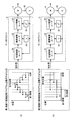
- FIG. 7 and 8 are diagrams for explaining the coordinate conversion according to the embodiment of the present invention.
- a machine coordinate system (XYZ coordinate system) with reference to the workpiece W shown in FIG. 6 and an axis coordinate system for each rotation angle of the servo motors 4-1, 4-2, 4-3 ( ( ⁇ 1- ⁇ 2- ⁇ 3 coordinate system).
- Fig. 7 consider a combination of two linear motions in the machine coordinate system. That is, the linear movement from the first start position (Xs1, Ys1, Zs1) to the first target position (Xe1, Ye1, Ze1), and the first target position (Xe2) from the second start position (Xs2, Ys2, Zs2). , Ye2, Ze2).
- the first target position (Xe1, Ye1, Ze1) and the second start position (Xs2, Ys2, Zs2) are the same.
- the temporal change in displacement at each coordinate in the machine coordinate system is as shown in FIG. That is, in each of the X-axis, Y-axis, and Z-axis, the coordinate position in each section changes primarily with respect to the time axis from a value corresponding to the start position to a value corresponding to the target position.
- each of the rotation angles ⁇ 1, ⁇ 2, and ⁇ 3 changes nonlinearly with respect to the time axis. .
- Such correspondence between the machine coordinate system and the axis coordinate system is expressed as follows using the position (X, Y, Z) in the machine coordinate system and the position ( ⁇ 1, ⁇ 2, ⁇ 3) in the axis coordinate system. It can be shown as follows.
- X f 1 ( ⁇ 1) + f 1 ( ⁇ 2) + f 1 ( ⁇ 3)
- Y f 2 ( ⁇ 1) + f 2 ( ⁇ 2) + f 2 ( ⁇ 3)
- Z f 3 ( ⁇ 1) + f 3 ( ⁇ 2) + f 3 ( ⁇ 3)
- ⁇ 1 g 1 (X) + g 1 (Y) + g 1 (Z)
- ⁇ 2 g 2 (Y) + g 2 (Y) + g 2 (Z)
- ⁇ 3 g 3 (Z) + g 3 (Z) + g 3 (Z) + g 3 (Z)
- the displacement amount of each servo motor 4 needs to be integrally controlled. Basically, it is not appropriate to drive only a specific axis alone.
- the PLC 1 provides a function for easily managing a plurality of servo motors related to the same motion operation and a user interface related thereto.
- FIG. 9 is a flowchart showing a control procedure related to motion control of PLC 1 according to the embodiment of the present invention.
- FIG. 9 shows a case where the calculation for calculating the motion control command value is executed in the first control cycle, and the process of changing the final target value is executed in the second control cycle.
- the microprocessor 100 of the CPU unit 13 of the PLC 1 executes an initial process (step S2).
- This initial processing includes setting of initial parameters, calculation of initial values, updating of network connection destinations, and the like.
- information about servo motor drivers 3 corresponding to a plurality of servo motors 4 involved in the same motion operation is acquired.
- the fact that a plurality of servo motors 4 are involved in the same motion control is also referred to as “belonging to an axis group”.
- step S4 the microprocessor 100 executes a device control process.
- This device control processing includes processing for setting a final target position in the machine coordinate system in accordance with various information (state values) obtained from the device to be controlled.
- step S6 the microprocessor 100 acquires a target position related to motion control (step S6). That is, the microprocessor 100 sequentially calculates the final target position (Xe, Ye, Ze) in the coordinate system (machine coordinate system) related to the same motion operation.
- the microprocessor 100 compares the current position with the acquired final target position, and determines whether or not the control target has reached the target position (step S8). If the control target has reached the final target position (YES in step S8), the second control cycle is advanced from the current cycle N to the next cycle N + 1 (step S10), and the processing from step S4 is executed again. Is done.
- the microprocessor 100 sets the target in the first coordinate system (machine coordinate system) in the current cycle n of the first control period.
- the position is calculated (step S12).
- the target position is calculated based on a process of calculating a trajectory from the current position to the final target position acquired in step S6 according to a rule (for example, an interpolation method) specified in advance, and based on the calculated trajectory. This includes processing for calculating a position (target position) to be moved in the current cycle n of one control cycle.
- the microprocessor 100 calculates a target position in the second coordinate system (axis coordinate system) corresponding to the target position acquired in Step S12 using a predetermined coordinate conversion function (Step S14). Subsequently, the microprocessor 100 determines, based on the deviation between the target position in the second coordinate system (axis coordinate system) and the current position in the second coordinate system in the current cycle n of the first control period, in the current control period. The amount ( ⁇ 1, ⁇ 2, ⁇ 3) to be moved for each axis is calculated (step S16). This amount to be moved becomes a command value for each servo motor driver.
- the microprocessor 100 monitors the states of the movements of the servo motors 4 belonging to the same axis group, and determines whether any of the movements of the servo motors 4 is abnormal (step). S18).
- step S18 If an abnormality occurs in any of the movements of the servo motor 4 (YES in step S18), the microprocessor 100 stops all the servo motors 4 belonging to the same axis group (step S20). Details of this stopping method will be described later.
- microprocessor 100 calculates in step S12 the command values for servo motors 4 belonging to the same axis group all at once. Output (step S22).
- step S24 After the first control cycle is advanced from the current cycle n to the next cycle n + 1 (step S24), the processing after step S12 is executed again.
- FIG. 10 is a functional block diagram relating to motion control of the PLC 1 according to the embodiment of the present invention.
- Each functional module shown in FIG. 10 is basically provided by the microprocessor 100 executing a control program 230 (typically an object format program).
- the CPU unit 13 has, as its control functions, a device control module 402, a coordinate conversion module 404, command value calculation / state management modules 406-1, 406-2,. And “monitoring module 410”.
- the device control module 402 sequentially calculates the final target position in the machine coordinate system in accordance with various information (state values) obtained from the device to be controlled.
- the sequentially calculated final target position of the machine coordinate system is given to the coordinate conversion module 404. That is, the apparatus control module 402 sequentially calculates the first target position in the first coordinate system related to the same motion operation.
- the coordinate conversion module 404 acquires the final target position from the apparatus control module 402, and calculates a trajectory from the current position to the final target position according to a rule specified in advance. Then, the coordinate conversion module 404 acquires a target position in the machine coordinate system in the current control cycle. Further, the coordinate conversion module 404 sequentially calculates a target position in the second coordinate system (axis coordinate system) corresponding to the target position in the machine coordinate system in accordance with a predetermined correspondence (conversion function).
- the second coordinate system (axis coordinate system) is defined by a plurality of axes ( ⁇ 1, ⁇ 2, ⁇ 3) respectively associated with the plurality of servo motors 4 involved in the same motion operation.
- the sequentially calculated target positions are output to the command value calculation / state management modules 406-1, 406-2, ..., 406-n. Note that only the component of the target position on the corresponding axis may be output to each of the command value calculation / state management module 406. That is, only the first axis component ( ⁇ 1) is output to the command value calculation / state management module 406-1 corresponding to the first axis.
- Each of the command value calculation / state management module 406 calculates a motion command value for the corresponding servo motor driver 3 (drive device) for each control cycle of motion control.
- Each of the command value calculation / status management modules 406 outputs the motion command value to the corresponding servo motor driver 3 for each control cycle at substantially the same timing as the other command value calculation / status management modules 406.
- the command value given to the servo motor driver 3 generally uses a number of pulses corresponding to the movement amount (displacement amount) from the current position.
- the servo motor driver 3 rotates the servo motor 4 by an angle corresponding to the number of pulses included in the command value.
- the coordinate conversion module 404 and the command value calculation / state management modules 406-1, 406-2,..., 406-n serve as target position calculation means and command value calculation means according to the present invention. Realize.
- the monitoring module 410 monitors the state of each of the plurality of servo motors 4 and responds to the occurrence of an abnormality in one of the plurality of servo motors 4 at the same time. To stop. More specifically, the monitoring module 410 acquires the status values of the respective servo motors 4 and servo motor drivers 3 via the command value calculation / status management module 406, and detects an abnormality based on the acquired status values. Judgment is made. As this abnormality, for example, the actual value (displacement feedback value) is not sufficiently obtained for the output command value, or an error due to an overcurrent has occurred in the servo motor driver 3. Including.
- FIG. 11 is a diagram for explaining tasks executed by the CPU unit 13 of the PLC 1 according to the embodiment of the present invention.
- FIG. 11A shows a case where a process related to motion control (first control period) and a process related to coordinate transformation (second control period) are both executed in a common control period.
- FIG. 11B shows a case where the control cycle of the process related to coordinate transformation is set to an integral multiple of the control cycle of the process related to motion control (twice in the example shown in FIG. 11B). .
- each of control cycles 1 to 4 represents a control cycle related to motion control.
- the control cycle (first control cycle) related to the motion control indicates a cycle in which a new command value is output to the servo motor driver 3 (the command value is updated). That is, in the servo motor driver 3, a new command value is given for each period corresponding to one control cycle.
- a function for converting a target position in a machine coordinate system to a target position in an axis coordinate system includes a nonlinear element such as a trigonometric function. For this reason, the process for calculating the target position of the axis coordinate system (that is, the coordinate conversion process) requires a large amount of calculation and requires a relatively long calculation time. Therefore, a task for determining the target position may be set as a task different from the process of calculating and outputting the command value to the servo motor driver 3.
- tasks related to motion control include O / I (Output / Input) processing, command value calculation processing (calculation of all command values belonging to the same axis group), and state monitoring processing.
- the task for determining the target position includes apparatus control processing and coordinate conversion processing.
- the task for determining the target position is repeatedly executed at every control cycle of motion control, and a machine coordinate system is generated using a process for generating a final target position and a function registered in advance. And converting the target position in to a target position in the axis coordinate system.
- Tasks related to motion control are repeatedly executed at every control cycle of motion control.
- each motion command value is calculated from the deviation between the current position and the target position in the axis coordinates.
- the task for determining the target position is repeatedly executed in the same control cycle as the task related to motion control. Therefore, the target position in the axis coordinate system calculated in each control cycle is executed in the next control cycle.
- the target position in the machine coordinate system is converted and the target position in the axis coordinate system is sequentially calculated, and the motion control is performed while minimizing the time delay from the target position conversion process. be able to.
- the example shown in FIG. 11B is more suitable when the amount of calculation related to coordinate conversion is relatively large.
- the task of determining the target position is executed repeatedly every cycle that is an integral multiple of the control cycle of motion control, and is determined along the trajectory from the current position to the final target position. Is converted into a target position in the axis coordinate system using a previously registered function.
- FIG. 12 is a diagram for explaining the control responsiveness accompanying the change in the control cycle shown in FIG.
- FIG. 12A shows a processing example in the case where the task for determining the target position is repeatedly executed at the same control cycle as the task related to motion control, corresponding to FIG. 11A.
- FIG. 12B shows an example of processing in the case where the task for determining the target position is repeatedly executed every cycle that is an integral multiple of the control cycle of motion control, corresponding to FIG. 11B. .
- the servo motor driver 3 employs an open loop type, and when viewed from the CPU unit 13 of the PLC 1, if a command value is given, the subsequent control is performed. Is executed in the servo motor driver 3. More specifically, the servo motor driver 3 includes a position control loop 31, a speed control loop 32, a torque control loop 33, a primary differentiator 34, and a secondary differentiator 35. Using these loop controls, torque control, speed control, and position control are performed using a given command value (target position) and a feedback actual value (position pulse).
- the command value is output in the control cycle next to the completion of the calculation of the target position in the axis coordinate system, and higher responsiveness can be realized.
- the command value is updated at each control period of the task related to coordinate conversion. Therefore, the responsiveness is slightly lowered as compared with the case of FIG.
- the CPU unit 13 executes target position interpolation processing in the command value calculation processing included in the task related to motion control. That is, the command value calculation process is repeatedly executed at every control cycle of motion control, and each motion command value is calculated from the deviation between the current position and the target position in the axis coordinate system. At this time, in the command value calculation process, each motion command value is calculated for each control cycle of the motion control by interpolating between the current position and the target position in the axis coordinate system.
- the target position correction method various known methods can be adopted. However, as the simplest method, the current position and the target position in the axis coordinate system are linearly interpolated and then the linear interpolation is performed. A method can be employed in which the midpoint of the trajectory obtained by the above is set as the target position in the first control cycle, and the given target position is set as the target position in the second control cycle.
- FIG. 11 described above shows an example in which two tasks can be executed independently in order to facilitate understanding.
- a configuration can be easily realized by adopting a multi-core processor having a plurality of cores as the microprocessor 100.
- priorities are determined in advance between tasks, and tasks with lower priorities are executed primarily during the period when tasks with higher priorities are executed. Task switching such as stopping at a later time may be performed.
- the control cycle of the coordinate conversion process can be set to an integral multiple of the control cycle of motion control. Even in such a case, the control accuracy of the motion control can be maintained by performing the interpolation processing of the target position as described above.
- the control program as described above is created by the PLC support device 8. That is, the PLC support device 8 corresponds to a support device for creating a program executed by the CPU unit 13 of the PLC 1 capable of motion control.
- FIG. 13 is a schematic diagram for explaining generation of the control program 230 executed by the PLC 1 according to the embodiment of the present invention.
- control program 230 according to the present embodiment includes device control program code 452, coordinate conversion program code 454, servo driver mapping information 472, group definition information 474, and library group 460. Generated.
- the device control program code 452 is a source code in which a program for controlling a control target is described. Sequence control logic for generating output data in accordance with whether or not a predetermined condition is satisfied for input data, , Including a logic for calculating and outputting a target position of the movement destination of the robot on condition that a predetermined condition is satisfied.
- the user operates a GUI (Graphical User Interface) provided by an editor program 321 (FIG. 5) executed on the PLC support device 8 to create a user program corresponding to the control target.
- the PLC support device 8 has a function of receiving a command for sequentially calculating the target position in the machine coordinate system related to the same motion operation.
- the coordinate conversion program code 454 includes source code and various settings for converting the target position of the machine coordinate system as described above into the target position of the axis coordinate system.
- a group of servo motor drivers 3 (and corresponding servo motors 4) belonging to the same axis group, which is a target of coordinate conversion, is designated. This designation method will be described later.
- the servo driver mapping information 472 is an address (identification information) on the bus and / or a field network when the servo motor driver 3 is connected to the CPU unit 13 via the PLC system bus 11 and / or the field network 2.
- 2 is information that defines each servo motor driver 3 in association with an address (identification information) 2.
- the group definition information 474 is information for defining the servo motor driver 3 (and corresponding servo motor 4) belonging to the same axis group.
- the servo motor driver 3 (and corresponding servo motor 4) belonging to each axis group is identified using the identification information (name) of the servo motor driver 3 defined in the servo driver mapping information 472. It is specified.
- the library group 460 is a data group including libraries, subroutines, modules, and the like necessary for generating the control program 230.
- the control program 230 is generated by incorporating some or all of the data during compilation.
- the library group 460 includes modules for basic functions provided by the CPU unit 13 according to the present embodiment, in addition to modules for realizing functions called in the device control program code 452. More specifically, the library group 460 includes data for realizing the monitoring module 410 shown in FIG.
- control program 230 in the object program format will be described, but the same applies to the case of using a control program in the mnemonic format or a similar format.
- functional modules corresponding to the library group 460 are built into the CPU unit 13 in the form of firmware or hardware.
- the compiler program 322 is executed by the PLC support device 8, so that the compilation process is executed and the control program 230 is generated. That is, the PLC support device 8 has a function of generating the control program 230 from the various input information as described above.
- FIG. 14 is a diagram showing an example of the device control program code 452 shown in FIG.
- FIG. 14 shows an example in which a coordinate conversion program is realized using a function block defined by IEC61131-3 as an example. That is, FIG. 14 shows a description example using a ladder language generally used in PLC.
- the contact 1 becomes TRUE (on)
- the input final target position Xe, Ye, Ze
- the input final target position Xe, Ye, Ze
- the user can define a function to be used for the coordinate transformation by tapping the coordinate transformation function block on an editor screen or the like displayed on the PLC support device 8.
- the PLC support device 8 accepts a correspondence (coordinate conversion function) for calculating the target position in the axis coordinate system corresponding to the target position in the machine coordinate system.
- the axis coordinate system is defined by a plurality of axes respectively associated with a plurality of servo motors 4 involved in the same motion operation.
- the user can set an arbitrary method (such as an interpolation method) for calculating a trajectory from the current position of the machine coordinate system to the final target position in the PLC support device 8.
- an arbitrary method such as an interpolation method
- the trajectory determination method for the final target value of the machine coordinate system, and the conversion function from the target position of the machine coordinate system to the target position of the corresponding axis coordinate system. Can be arbitrarily set by the user. Therefore, unlike the conventional case, there is no need for a dedicated motion controller to hold information such as a conversion function.
- FIG. 15 is a diagram showing an example of a user interface screen 500 for setting the group definition information 474 shown in FIG.
- user interface screen 500 is provided by PLC support device 8.
- an input box 502 for selecting an axis group number an input box 504 for selecting whether to enable / disable the axis group function, and an input box 506 for inputting the number of axes included in the axis group are selected.
- FIG. 15 shows a situation where the axis group “0” is selected. Subsequently, in order to validate the axis group function, the user selects “Using Group” in the input box 504 (which means that the axis group is used). Further, the user inputs the number of axes belonging to the selected axis group in the input box 506. The example shown in FIG. 15 shows an example in which “2” axes are selected.
- the PLC support device 8 displays an image 508 of the device corresponding to the number of input axes according to the number of axes input to the input box 506.
- the example shown in FIG. 16 shows an example in which a device that moves in two directions is conceptually displayed.
- the user designates the servo motor driver 3 belonging to the selected axis group in the input list 510.
- an axis group including two axes is set, and “MC_Axis000 (0)” and “MC_Axis000 (1)” are designated as the servo motor driver 3 belonging to this axis group.
- the PLC support device 8 has a function of receiving designation of servo motor drivers 3 (drive devices) corresponding to a plurality of servo motors 4 involved in the same motion operation.
- This designated information is stored as group definition information 474 (FIG. 13).
- Information (group definition information 474) for designating the servo motor driver 3 (driving device) corresponding to the plurality of servo motors 4 involved in the same motion operation is incorporated into the control program 230, and substantially CPU It is stored in the unit 13.
- the group definition information 474 may be stored in the memory of the CPU unit 13 as it is. In this way, the servo motor driver 3 belonging to the same axis group can be changed more easily.
- the PLC support device 8 can appropriately select a stopping method in such a simultaneous stop according to the application to which the application is applied.
- the method of stopping a plurality of servo motors 4 at a time can basically be arbitrarily selected from the following three methods.
- a method for simultaneously setting each motion command value corresponding to a plurality of servo motors to zero (2) A method for stopping a plurality of servo motors independently from each other at a deceleration acceleration allowed for the corresponding axis (3) ) A method to reduce the speed while maintaining the trajectory determined from the relationship between the current position and the target position of the machine coordinate system. Furthermore, the processing to reset the deviation in the control logic and the servo motor at the time of deceleration Processing for invalidating the monitoring of the acceleration / jerk 4 may be further added.
- FIG. 16 is a diagram showing an example of a user interface screen 600 for designating a stop method provided by the PLC support device 8 according to the embodiment of the present invention.
- FIG. 17 is a diagram for explaining a stop operation corresponding to each mode selected in FIG.
- modes 601 to 604 correspond to any one of the above-described stop operations (1) to (3).
- FIG. 17A shows the stop operation when any one of these modes is selected. That is, as shown in FIG. 17A, if an abnormality occurs in any one of the servo motor drivers 3 (and corresponding servo motors 4), the other servo motor drivers 3 (and The command values including the corresponding servo motors 4) are simultaneously changed to “0”.
- the above-described method (2) in which a plurality of servo motors are stopped independently of each other with the deceleration acceleration allowed on the corresponding axis, corresponds to mode 602.
- the stop operation when this mode is selected is shown in FIG. That is, as shown in FIG. 17B, if an abnormality occurs in any one of the servo motor drivers 3 (and corresponding servo motors 4), the respective servo motor drivers 3 (and The corresponding servo motor 4) has its command value reduced to “0” in accordance with the allowable deceleration acceleration ⁇ 1 to ⁇ 3.
- the timing at which the command value actually becomes “0” may be different depending on the magnitude (absolute value) of each command value and the maximum deceleration acceleration.
- this method can stop the operation most quickly while reducing the possibility of mechanical breakage in each axis.
- the above-described (3) method of reducing the speed while maintaining the trajectory determined from the relationship between the current position and the target position of the machine coordinate system corresponds to mode 601.
- the stop operation when this mode is selected is shown in FIG. That is, as shown in FIG. 17C, if an abnormality occurs in any of the servo motor drivers 3 (and corresponding servo motors 4), each servo motor driver 3 (and The corresponding servo motor 4) reduces the overall speed to "0" while keeping the planned trajectory. In this case, since the planned trajectory can be observed even during the stop operation, it can be stopped more safely.
- the CPU unit 13 is a controller (motion controller) capable of controlling a mechanical device that needs to perform coordinate conversion between an axis coordinate system of the servo motor and a machine coordinate system of the mechanical mechanism. .
- the CPU unit 13 can realize an operation method that realizes a desired operation by giving a target position to each of a plurality of axes in each control cycle by a user program. At the same time, the CPU unit 13 provides a function for collectively monitoring abnormalities on these multiple axes, so that it is necessary to remodel the motion controller one by one when adding a coordinate conversion formula according to the mechanical mechanism. There is no. Furthermore, the user does not need to monitor the axis state individually for each axis.
- the CPU unit 13 is a motion controller that controls a mechanical device that needs to perform coordinate conversion between the axis coordinate system of the servo motor and the coordinate system of the mechanical mechanism.
- the user can create a coordinate conversion program for converting the coordinates of the mechanical mechanism into the axis coordinates of the motor.
- This coordinate conversion program can give independent target positions for at least two axes in each control cycle, and command the command value to reach the target position in the next control cycle to the motor driver for each axis. It has the function to do.
- the CPU unit 13 repeats the program for calculating the command value for each axis for each first fixed period, and repeats the coordinate conversion program for each first fixed period.
- the CPU unit 13 repeats the program for calculating the command value for each axis for each first fixed period, and the second standard conversion program is an integer multiple of the first fixed period. It can also be repeated at regular intervals.
- the CPU unit 13 according to the present embodiment has a function of stopping the operation of the remaining axes when at least one of the axes to be operated simultaneously becomes abnormal. Furthermore, the CPU unit 13 according to the present embodiment can be stopped so as to keep the target trajectory, stop at the maximum current speed of each axis, stop immediately, or immediately stop and deviation. It has a function that allows the user to specify whether to perform reset processing or stop and stop the servo feedback of the axis.
- any axis belonging to the same axis group has an abnormality, it can be stopped including other axes.
- an error occurs in these multiple axes. It is possible to solve the conventional problem that it is complicated because it is necessary to implement in the user program whether or not the problem has occurred and how to stop it when it occurs.
- the trajectory determination method for the final target value of the machine coordinate system and the conversion function from the target position of the machine coordinate system to the target position of the corresponding axis coordinate system Can be set arbitrarily. Therefore, unlike the conventional case, there is no need for a dedicated motion controller to hold information such as a conversion function. Even when new mechanical mechanisms are introduced, the user can easily set the trajectory interpolation method and coordinate conversion function corresponding to the mechanical mechanism, so it is possible to handle these new mechanical mechanisms without cost and effort. it can.
Abstract
L'unité de calcul faisant l'objet de la présente invention comporte : un moyen de calcul de position visée qui calcule de manière séquentielle des premières positions visées dans un premier système de coordonnées en ce qui concerne la même opération de mouvement ; et un moyen de calcul de valeurs de commande qui calcule des valeurs de commande de mouvement pour un dispositif d'entraînement désigné lors de chaque cycle de commande de la commande de mouvement grâce au calcul séquentiel de secondes positions visées dans un second système de coordonnées correspondant à la première position visée en fonction d'une concordance prédéfinie. Selon la présente invention, le second système de coordonnées est délimité par une pluralité d'axes associés respectivement à une pluralité de moteurs qui sont impliqués dans la même opération de mouvement. Ladite unité de calcul comporte en outre un moyen de sortie qui transmet par lots les valeurs de commande de mouvement respectives pour la pluralité de moteurs lors de chaque cycle de commande de la commande de mouvement.
Applications Claiming Priority (2)
| Application Number | Priority Date | Filing Date | Title |
|---|---|---|---|
| JP2011-056770 | 2011-03-15 | ||
| JP2011056770 | 2011-03-15 |
Publications (1)
| Publication Number | Publication Date |
|---|---|
| WO2012124145A1 true WO2012124145A1 (fr) | 2012-09-20 |
Family
ID=46830257
Family Applications (1)
| Application Number | Title | Priority Date | Filing Date |
|---|---|---|---|
| PCT/JP2011/056781 WO2012124145A1 (fr) | 2011-03-15 | 2011-03-22 | Unité de calcul, unité d'assistance, programme d'assistance, support d'enregistrement contenant un programme d'assistance, et procédé de fonctionnement dans un dispositif d'assistance |
Country Status (1)
| Country | Link |
|---|---|
| WO (1) | WO2012124145A1 (fr) |
Cited By (3)
| Publication number | Priority date | Publication date | Assignee | Title |
|---|---|---|---|---|
| JP2015176369A (ja) * | 2014-03-14 | 2015-10-05 | オムロン株式会社 | 制御装置 |
| CN113759851A (zh) * | 2021-09-16 | 2021-12-07 | 无锡积塔技术有限公司 | 自动化控制系统以及自动化控制方法 |
| WO2022185830A1 (fr) * | 2021-03-03 | 2022-09-09 | 村田機械株式会社 | Système de moteur |
Citations (6)
| Publication number | Priority date | Publication date | Assignee | Title |
|---|---|---|---|---|
| US5151350A (en) | 1982-10-27 | 1992-09-29 | Repligen Corporation | Cloned genes encoding recombinant protein a |
| JPH0481143B2 (fr) | 1984-02-08 | 1992-12-22 | Hitachi Ltd | |
| JPH06281638A (ja) | 1993-03-25 | 1994-10-07 | Ngk Insulators Ltd | アフィニティクロマトグラフィー用充填剤 |
| JPH11231915A (ja) * | 1998-02-12 | 1999-08-27 | Yaskawa Electric Corp | モーション制御装置の軸の定義方法 |
| JP2001147706A (ja) * | 1999-11-22 | 2001-05-29 | Sony Corp | アクチュエータ駆動制御方式、多軸機械装置、及びアクチュエータのための駆動制御装置 |
| JP4391830B2 (ja) | 2002-03-25 | 2009-12-24 | ジーイー・ヘルスケア・バイオサイエンス・アクチボラグ | 変異免疫グロブリン結合タンパク質 |
-
2011
- 2011-03-22 WO PCT/JP2011/056781 patent/WO2012124145A1/fr active Application Filing
Patent Citations (6)
| Publication number | Priority date | Publication date | Assignee | Title |
|---|---|---|---|---|
| US5151350A (en) | 1982-10-27 | 1992-09-29 | Repligen Corporation | Cloned genes encoding recombinant protein a |
| JPH0481143B2 (fr) | 1984-02-08 | 1992-12-22 | Hitachi Ltd | |
| JPH06281638A (ja) | 1993-03-25 | 1994-10-07 | Ngk Insulators Ltd | アフィニティクロマトグラフィー用充填剤 |
| JPH11231915A (ja) * | 1998-02-12 | 1999-08-27 | Yaskawa Electric Corp | モーション制御装置の軸の定義方法 |
| JP2001147706A (ja) * | 1999-11-22 | 2001-05-29 | Sony Corp | アクチュエータ駆動制御方式、多軸機械装置、及びアクチュエータのための駆動制御装置 |
| JP4391830B2 (ja) | 2002-03-25 | 2009-12-24 | ジーイー・ヘルスケア・バイオサイエンス・アクチボラグ | 変異免疫グロブリン結合タンパク質 |
Non-Patent Citations (4)
| Title |
|---|
| "Molecular Cloning", 2001, COLD SPRING HARBOR LABORATORY PRESS |
| FREDERICK M. AUSBEL ET AL., CURRENT PROTOCOLS IN MOLECULAR BIOLOGY |
| J. MATER. CHEM., vol. 1, no. 3, 1991, pages 371 - 374 |
| NILSSON B. ET AL., PROTEIN ENGINEERING, vol. 1, no. 2, 1987, pages 107 - 113 |
Cited By (7)
| Publication number | Priority date | Publication date | Assignee | Title |
|---|---|---|---|---|
| JP2015176369A (ja) * | 2014-03-14 | 2015-10-05 | オムロン株式会社 | 制御装置 |
| CN106062646A (zh) * | 2014-03-14 | 2016-10-26 | 欧姆龙株式会社 | 控制装置 |
| US10228675B2 (en) | 2014-03-14 | 2019-03-12 | Omron Corporation | Controlling one or more devices upon detecting abnormal behavior |
| CN106062646B (zh) * | 2014-03-14 | 2019-11-08 | 欧姆龙株式会社 | 控制装置 |
| WO2022185830A1 (fr) * | 2021-03-03 | 2022-09-09 | 村田機械株式会社 | Système de moteur |
| CN113759851A (zh) * | 2021-09-16 | 2021-12-07 | 无锡积塔技术有限公司 | 自动化控制系统以及自动化控制方法 |
| CN113759851B (zh) * | 2021-09-16 | 2024-03-12 | 无锡积塔技术有限公司 | 自动化控制系统以及自动化控制方法 |
Similar Documents
| Publication | Publication Date | Title |
|---|---|---|
| JP4905597B1 (ja) | コントローラサポート装置、その装置において実行されるためのコントローラサポートプログラム、およびそのプログラムを格納する記録媒体 | |
| Martinov et al. | From classic CNC systems to cloud-based technology and back | |
| WO2012124143A1 (fr) | Unité de calcul, dispositif d'assistance, procédé de commande de sortie, procédé de commande d'affichage et programme | |
| JP6540166B2 (ja) | 制御装置 | |
| JP4973792B1 (ja) | 演算ユニット、出力制御方法、およびプログラム | |
| JP6409557B2 (ja) | 制御装置、コントローラ・システム、出力制御方法、およびプログラム | |
| EP2515189B1 (fr) | Unité cpu de plc, programme de système pour plc et support de stockage dans lequel est stocké un programme de système pour plc | |
| US8504176B2 (en) | CPU unit of PLC, system program for PLC, and recording medium storing system program for PLC | |
| US8901870B2 (en) | Synchronous control apparatus | |
| JP6299064B2 (ja) | 制御装置、制御方法、およびプログラム | |
| JP6729746B2 (ja) | 制御装置 | |
| JP4748286B1 (ja) | コントローラサポート装置、その装置において実行されるためのコントローラサポートプログラム、そのプログラムを格納した記録媒体、および、制御プログラムの実行時間を推定する方法 | |
| EP3441831B1 (fr) | Dispositif de traitement d'informations, procédé de traitement d'informations et programme de traitement d'informations | |
| EP3441830A1 (fr) | Dispositif de traitement d'informations, procédé de traitement d'informations et programme de traitement d'informations | |
| WO2012124145A1 (fr) | Unité de calcul, unité d'assistance, programme d'assistance, support d'enregistrement contenant un programme d'assistance, et procédé de fonctionnement dans un dispositif d'assistance | |
| WO2021181801A1 (fr) | Procédé de commande et système de commande de robot | |
| US11855907B2 (en) | Robot control system and control method | |
| WO2012124137A1 (fr) | Cpu de plc, programme de système pour plc et support d'enregistrement stockant un programme de système pour plc | |
| JP7375632B2 (ja) | 制御システムおよびサポート装置 | |
| WO2022162959A1 (fr) | Système de commande, contrôleur de robot et procédé de commande | |
| JP7167516B2 (ja) | 制御装置、制御方法、および制御プログラム | |
| WO2022168336A1 (fr) | Dispositif de commande, procédé de commande et programme de commande | |
| JP2012194955A (ja) | 支援装置、表示制御方法、およびプログラム | |
| WO2021181800A1 (fr) | Procédé de commande et système de commande de robot |
Legal Events
| Date | Code | Title | Description |
|---|---|---|---|
| 121 | Ep: the epo has been informed by wipo that ep was designated in this application |
Ref document number: 11861165 Country of ref document: EP Kind code of ref document: A1 |
|
| NENP | Non-entry into the national phase |
Ref country code: DE |
|
| 122 | Ep: pct application non-entry in european phase |
Ref document number: 11861165 Country of ref document: EP Kind code of ref document: A1 |