WO2012124062A1 - 流量計測装置 - Google Patents
流量計測装置 Download PDFInfo
- Publication number
- WO2012124062A1 WO2012124062A1 PCT/JP2011/056104 JP2011056104W WO2012124062A1 WO 2012124062 A1 WO2012124062 A1 WO 2012124062A1 JP 2011056104 W JP2011056104 W JP 2011056104W WO 2012124062 A1 WO2012124062 A1 WO 2012124062A1
- Authority
- WO
- WIPO (PCT)
- Prior art keywords
- exhaust gas
- flow rate
- laser
- image
- calculated
- Prior art date
Links
Images


Classifications
-
- G—PHYSICS
- G01—MEASURING; TESTING
- G01F—MEASURING VOLUME, VOLUME FLOW, MASS FLOW OR LIQUID LEVEL; METERING BY VOLUME
- G01F1/00—Measuring the volume flow or mass flow of fluid or fluent solid material wherein the fluid passes through a meter in a continuous flow
- G01F1/66—Measuring the volume flow or mass flow of fluid or fluent solid material wherein the fluid passes through a meter in a continuous flow by measuring frequency, phase shift or propagation time of electromagnetic or other waves, e.g. using ultrasonic flowmeters
- G01F1/661—Measuring the volume flow or mass flow of fluid or fluent solid material wherein the fluid passes through a meter in a continuous flow by measuring frequency, phase shift or propagation time of electromagnetic or other waves, e.g. using ultrasonic flowmeters using light
-
- G—PHYSICS
- G01—MEASURING; TESTING
- G01F—MEASURING VOLUME, VOLUME FLOW, MASS FLOW OR LIQUID LEVEL; METERING BY VOLUME
- G01F1/00—Measuring the volume flow or mass flow of fluid or fluent solid material wherein the fluid passes through a meter in a continuous flow
- G01F1/704—Measuring the volume flow or mass flow of fluid or fluent solid material wherein the fluid passes through a meter in a continuous flow using marked regions or existing inhomogeneities within the fluid stream, e.g. statistically occurring variations in a fluid parameter
- G01F1/708—Measuring the time taken to traverse a fixed distance
- G01F1/7086—Measuring the time taken to traverse a fixed distance using optical detecting arrangements
-
- G—PHYSICS
- G01—MEASURING; TESTING
- G01F—MEASURING VOLUME, VOLUME FLOW, MASS FLOW OR LIQUID LEVEL; METERING BY VOLUME
- G01F1/00—Measuring the volume flow or mass flow of fluid or fluent solid material wherein the fluid passes through a meter in a continuous flow
- G01F1/76—Devices for measuring mass flow of a fluid or a fluent solid material
- G01F1/86—Indirect mass flowmeters, e.g. measuring volume flow and density, temperature or pressure
-
- G—PHYSICS
- G01—MEASURING; TESTING
- G01P—MEASURING LINEAR OR ANGULAR SPEED, ACCELERATION, DECELERATION, OR SHOCK; INDICATING PRESENCE, ABSENCE, OR DIRECTION, OF MOVEMENT
- G01P5/00—Measuring speed of fluids, e.g. of air stream; Measuring speed of bodies relative to fluids, e.g. of ship, of aircraft
- G01P5/26—Measuring speed of fluids, e.g. of air stream; Measuring speed of bodies relative to fluids, e.g. of ship, of aircraft by measuring the direct influence of the streaming fluid on the properties of a detecting optical wave
-
- G—PHYSICS
- G01—MEASURING; TESTING
- G01F—MEASURING VOLUME, VOLUME FLOW, MASS FLOW OR LIQUID LEVEL; METERING BY VOLUME
- G01F1/00—Measuring the volume flow or mass flow of fluid or fluent solid material wherein the fluid passes through a meter in a continuous flow
- G01F1/704—Measuring the volume flow or mass flow of fluid or fluent solid material wherein the fluid passes through a meter in a continuous flow using marked regions or existing inhomogeneities within the fluid stream, e.g. statistically occurring variations in a fluid parameter
- G01F1/708—Measuring the time taken to traverse a fixed distance
- G01F1/712—Measuring the time taken to traverse a fixed distance using auto-correlation or cross-correlation detection means
Definitions
- the present invention relates to a flow rate measuring device for measuring a flow rate of a fluid, and more particularly to a technique for measuring a mass flow rate of exhaust gas discharged from an engine provided in an automobile or the like by image processing.
- a flow measurement device for measuring a mass flow rate of gas a differential pressure type flow measurement device using a Pitot tube or an orifice plate, an ultrasonic flow measurement device using an ultrasonic sensor, and a lamina having a plurality of tubes
- a laminar flow rate measuring device using an element, a hot wire type flow measuring device using a heater (heat wire), and the like are widely known.
- the flow rate measuring device when measuring the mass flow rate of exhaust gas discharged from an engine provided in an automobile or the like, it is difficult to employ the flow rate measuring device as described above. This is because the exhaust gas contains (1) substances other than gas components (water droplets condensed with water vapor, unburned fuel, engine oil, etc.), and (2) the fluctuation range of the flow rate due to changes in temperature, engine speed, etc. (3) It includes pressure pulsations proportional to the engine speed and the number of cylinders, and (4) the flow is biased due to the influence of the curved portion of the exhaust pipe. This is because the mass flow rate of the exhaust gas cannot be measured with high accuracy by the above flow rate measuring device due to the characteristics of the exhaust gas shown in (4) to (4).
- Patent Document 1 discloses an apparatus for analyzing a fluid flowing in a duct by PIV (Particle Image Velocity) processing.
- the apparatus described in Patent Document 1 irradiates a sheet-like laser into a duct in which a fluid flows at two times separated by a minute time interval, and at the same time, cuts the internal space of the duct by the sheet-like laser.
- the amount of movement of the fluid particles is calculated based on the captured images at the two times.
- the mass flow rate of the fluid flowing in the duct can be calculated by using the calculated movement amount of the fluid particles.
- Patent Document 1 can image an arbitrary place in the duct, it does not take into account the deviation of the flow of the fluid, and when used to measure the mass flow rate of exhaust gas, The mass flow rate of exhaust gas cannot be measured with high accuracy.
- An object of the present invention is to provide a flow rate measuring device capable of accurately measuring the mass flow rate of exhaust gas.
- the flow rate measuring device of the present invention is a flow rate measuring device for measuring the mass flow rate of exhaust gas discharged from an engine, wherein the exhaust gas flows inside with a tracer, an irradiation unit for irradiating a laser, and the irradiation unit Is reflected as a sheet-shaped laser that cuts the internal space of the duct along the flow direction of the exhaust gas, and the sheet-shaped laser is reflected in a direction orthogonal to the flow direction of the exhaust gas.
- An image capturing unit that captures an image of a cut surface of the internal space of the duct, and a control that calculates a mass flow rate of the exhaust gas.
- the laser distributor, and the laser distributor travels the sheet-like laser in the entire range in the duct along the transition direction.
- the imaging unit synchronizes the time obtained by dividing one period into a plurality of equal periods, and the imaging time as one period, with one period of time for the sheet-like laser to make one round trip in the duct as one period.
- the control operation unit captures the plurality of images for two consecutive periods as the time shorter than the time obtained by equally dividing the plurality of images at a predetermined time interval. And the movement vector of the exhaust gas per cycle at a plurality of coordinates on each image is calculated based on the plurality of images for two consecutive cycles, and the exhaust gas at a plurality of coordinates on each image is calculated.
- the movement vector is averaged as one movement vector, the component in the flow direction of the exhaust gas in one movement vector averaged on each image is defined as the movement amount of the exhaust gas, and the previous image in the plurality of images
- the arithmetic average of the movement amount of the exhaust gas is used as the representative movement amount of the exhaust gas, the actual flow rate of the exhaust gas is calculated from the representative movement amount of the exhaust gas, the actual flow rate of the exhaust gas is calculated from the actual flow rate of the exhaust gas, Based on the actual flow rate, the mass flow rate of the exhaust gas is calculated.
- the imaging time of each image by the imaging unit is half of the time obtained by dividing one period into a plurality of equal parts.
- the control calculation unit uses the movement vector of the exhaust gas at a plurality of coordinates on each image calculated at a time interval smaller than one cycle, and at a time interval of one cycle. It is preferable to remove an error vector from the calculated movement vector of the exhaust gas at a plurality of coordinates on each image.
- the control calculation unit extracts the contour lines of the exhaust gas concentration in the plurality of images for two consecutive cycles, and the two consecutive cycles in which the contour lines of the exhaust gas concentration are extracted. It is preferable to calculate the movement vector of the exhaust gas at a plurality of coordinates on each image based on the plurality of images.
- an absolute pressure gauge that measures the absolute pressure of the exhaust gas flowing in the duct
- a tubular bypass that is attached to the duct at both ends so as to communicate with the inside of the duct
- a pressure gauge that measures the pressure of the exhaust gas flowing in the bypass
- the control calculation unit is configured to control the bypass based on the pressure of the exhaust gas flowing in the bypass measured by the pressure gauge.
- the primary natural frequency of the air column in the bypass is calculated
- the sound speed in the bypass is calculated from the primary natural frequency of the air column in the bypass
- the sound speed in the exhaust gas atmosphere is calculated from the sound speed in the bypass.
- the flow rate measuring device of the present invention further includes an air-fuel ratio meter that measures an air-fuel ratio of the exhaust gas flowing in the duct, and the control calculation unit is the air-fuel ratio of the exhaust gas and the source of the exhaust gas It is preferable to calculate the average molecular weight of the exhaust gas based on the properties of the fuel, calculate the density of the exhaust gas from the average molecular weight of the exhaust gas, and calculate the mass flow rate of the exhaust gas based on the density of the exhaust gas.
- the mass flow rate of exhaust gas can be accurately measured.
- the figure which shows the flow measuring device in one Embodiment of this invention The block diagram which shows the relationship with respect to the control calculating part of a laser distributor, an imaging part, an absolute pressure gauge, an air fuel ratio meter, and a temperature measurement part.
- the flowchart which shows the calculation process of the mass flow rate of waste gas.
- FIG. 1 It is a figure which shows the mode of a PIV process
- (a) is a figure which shows the image imaged at 1st time
- (b) is a figure which shows the image imaged at 2nd time
- (c) is a figure.
- (a) is a figure which shows a grayscale image
- (b) is a figure which shows a contour-line image.
- attain the predetermined speed between a tracer and a disturbance substance It is a figure which shows the difference in distribution of the movement amount between a tracer and a disturbance substance, (a) is a figure which shows distribution of the movement amount of a tracer and a disturbance substance in the time interval for 1 period, (b), The figure which shows distribution of the movement amount of a tracer and a disturbance substance in the time interval smaller than 1 period. The figure which showed a mode that an error vector was removed.
- the flow rate measuring device 1 is a device that measures the flow rate (strictly speaking, mass flow rate M [kg / s]) of exhaust gas discharged from an engine provided in an automobile or the like.
- the direction indicated by the arrow Y in FIG. 1 is the exhaust gas flow direction, the upstream side in the exhaust gas flow direction is simply referred to as “upstream side”, and the downstream side in the exhaust gas flow direction is simply referred to as “downstream side”.
- the front-rear direction is defined with the direction indicated by the arrow X in FIG. 1 as the rear direction of the flow rate measuring device 1, and the up-down direction is defined with the direction indicated by the arrow Z in FIG.
- the flow rate measuring device 1 includes a tracer introduction tube 10, a laser introduction tube 20, an irradiation unit 30, a laser distributor 40, an imaging unit 50, absolute pressure gauges 60 and 60, an air-fuel ratio meter 70, and a temperature measurement unit. 80 and a control calculation unit 90 (see FIG. 2).
- the tracer introduction pipe 10 is a substantially cylindrical duct, and is arranged on the flow path of the exhaust gas so that the exhaust gas flows inside. Specifically, the tracer introduction pipe 10 is connected to an exhaust pipe E1 of an automobile or the like at the upstream end portion. Inside the tracer introduction pipe 10, the tracer stored in the tracer distributor 11 is introduced, and the tracer flows in the tracer introduction pipe 10 together with the exhaust gas.
- the tracer is a particulate substance used for visualizing exhaust gas.
- the tracer distributor 11 is a member that stores a predetermined amount of tracer, and supplies the tracer to the inside of the tracer introduction pipe 10.
- the tracer introduction tube 10 is connected to the laser introduction tube 20 at its downstream end. That is, the tracer introduction tube 10 is disposed on the upstream side, and the laser introduction tube 20 is disposed on the downstream side.
- the laser introduction tube 20 is a cylindrical duct, and has an outer peripheral shape formed in a substantially rectangular parallelepiped shape and an inner peripheral shape that is flush with the inner peripheral surface of the tracer introduction tube 10. Similarly to the tracer introduction tube 10, the laser introduction tube 20 is arranged on the flow path of the exhaust gas so that the exhaust gas flows inside. Specifically, the laser introduction pipe 20 is connected to an exhaust pipe E2 of an automobile or the like at the downstream end thereof. Thus, the exhaust gas flowing from the exhaust pipe E1 into the tracer introduction pipe 10 is mixed with the tracer in the tracer introduction pipe 10, flows to the laser introduction pipe 20, and then flows out to the exhaust pipe E2.
- the irradiation unit 30 is a member that irradiates a laser beam toward the laser distributor 40.
- the laser distributor 40 is a member that reflects the beam-shaped laser irradiated from the irradiation unit 30 as a sheet-shaped laser that cuts the internal space of the laser introduction tube 20 along the flow direction of the exhaust gas. A (Micro Electro Mechanical Systems) mirror or the like is applied.
- the laser distributor 40 is swingably provided on a shaft 41 extending in parallel with the flow direction of the exhaust gas, and is disposed above the laser introduction tube 20.
- the laser distributor 40 causes a sheet-like laser to enter the laser introducing tube 20 through a laser introducing window 21 formed on the upper surface of the laser introducing tube 20 at an angle corresponding to the swing angle.
- the laser introduction window 21 is made of a material having transparency capable of introducing a sheet-like laser formed by the laser distributor 40 into the laser introduction tube 20, and the laser introduction tube 20 is formed on the upper surface of the laser introduction tube 20. 20 is formed from the outer peripheral surface to the inner peripheral surface.
- the imaging unit 50 is a member that images a cut surface of the internal space of the laser introduction tube 20 by a sheet-like laser through an imaging window 22 formed on the front surface of the laser introduction tube 20.
- the imaging unit 50 is disposed in front of the imaging window 22 so that the imaging direction and the flow direction of the exhaust gas are orthogonal to each other. Therefore, the image captured by the imaging unit 50 is an image on the YZ plane (a plane formed by the exhaust gas flow direction and the vertical direction).
- the imaging window 22 is a transparent member that enables the inside of the laser introduction tube 20 to be imaged from the outside of the laser introduction tube 20. From the outer peripheral surface of the laser introduction tube 20 on the front surface of the laser introduction tube 20. It is formed over the inner peripheral surface.
- the absolute pressure gauges 60 and 60 are members that measure the absolute pressure Pm [kPa ⁇ abs] of the exhaust gas in the flow rate measuring device 1.
- the absolute pressure gauges 60 and 60 are respectively arranged on the upstream side and the downstream side of the laser introduction tube 20 so as to sandwich the laser introduction window 21 on the upper surface of the laser introduction tube 20.
- the average value of the absolute pressure of the exhaust gas at two different positions (upstream and downstream of the laser introduction tube 20) measured by the absolute pressure gauges 60 and 60 is the absolute pressure Pm of the portion of the exhaust gas irradiated with the sheet-like laser. Treated as [kPa ⁇ abs].
- the absolute pressure of the exhaust gas measured by one absolute pressure gauge 60 can be set to the absolute pressure Pm [kPa ⁇ abs] of the portion of the exhaust gas irradiated with the sheet-like laser.
- the air-fuel ratio meter 70 is a member that measures the air-fuel ratio Rm of the exhaust gas in the flow rate measuring device 1, and is disposed on the upper part of the tracer introduction pipe 10.
- the temperature measuring unit 80 is a member that measures the instantaneous temperature Tm [° C.] of the exhaust gas in the flow rate measuring device 1, and includes a bypass 81 and a pressure gauge 82. Strictly speaking, the instantaneous temperature Tm [° C.] of the exhaust gas is not directly measured by the temperature measuring unit 80, but is measured by the pressure gauge 82, and the pressure of the exhaust gas flowing in the bypass 81, and It is calculated based on the air-fuel ratio Rm and the like. Details of the method for calculating the instantaneous temperature Tm [° C.] of the exhaust gas will be described later.
- the bypass 81 is a tubular member that communicates with the inside of the laser introduction tube 20 and is disposed on the downstream side of the imaging window 22. Both ends of the bypass 81 are attached to the lower surface of the laser introduction tube 20 so that the inside of the bypass 81 and the inside of the laser introduction tube 20 communicate with each other in a state of being separated from each other along the flow direction of the exhaust gas.
- the pressure gauge 82 is a member that measures the pressure of the exhaust gas flowing in the bypass 81, and is attached to the bypass 81.
- control calculation unit 90 is electrically connected to the laser distributor 40 and the imaging unit 50, and controls the operations of the laser distributor 40 and the imaging unit 50.
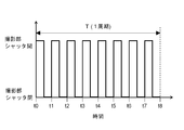
- the control calculation unit 90 sets the laser distributor 40 to a predetermined value so that the sheet-like laser reflected by the laser distributor 40 changes over the entire range in the front-rear direction in the laser introduction tube 20. It is swung in a range (range from the position P1 to the position P2 of the laser distributor 40 indicated by a two-dot chain line in FIG. 3). Assuming that the position P1 shown in FIG. 3 is the initial position of the laser distributor 40, the laser distributor 40 rotates to the position P2 and returns to the position P1 again (one reciprocation). T [s] ”). In other words, the period of time for which the sheet-like laser reflected by the laser distributor 40 reciprocates once in the entire range in the front-rear direction in the laser introduction tube 20 is the period T [s].
- the elapsed time is t1, the time T / n [s] from t1 is t2, the time T / n [s] from t2 is t3, and the time T / n [s] has elapsed from t3 That is, the time when the laser distributor 40 reaches the position P2 is t4, the time when T / n [s] has elapsed from t4 is t5, the time after T / n [s] has elapsed from t5 is t6, and the time from t6 to T
- the time when / n [s] has elapsed is denoted by t7, and the time when T / n [s] has elapsed since t
- the laser distributor 40 is rotated from the position P1 to the position P2 in a time period from t0 to t4 (T / 2 [s]), which is a period T [s. ] Is the forward path of the sheet-like laser. Further, as shown in FIG. 3 (b), the laser distributor 40 rotates from the position P2 to the position P1 in the time from t4 to t8 (T / 2 [s]), and this is in the period T [s]. It becomes the return path of the sheet-like laser.
- the laser distributor 40 By oscillating the laser distributor 40 in this way, the irradiation position of the sheet-shaped laser extending along the flow direction of the exhaust gas changes, and the laser is T / 2 [s], and the laser introduction tube 20 is at T / 2 [s]. It is distributed over the entire range in the front-rear direction.
- Imaging is performed until the time elapses (see the range of A3 in FIG. 3A), and imaging is performed until T / 2n [s] elapses from t3 (see the range of A4 in FIG. 3A). Imaging is performed until 2n [s] has elapsed (see the range of A5 in FIG. 3B), imaging is performed until T / 2n [s] has elapsed from t5 (see the range of A6 in FIG. 3B), Imaging is performed until T / 2n [s] elapses from t6 (A7 in FIG. 3B). Range reference), performing imaging until after T / 2n [s] from t7 reference range of A8 in ( Figure 3 (b)).
- FIG. 4 The state of the shutter of the imaging unit 50 at this time is shown in FIG. According to FIG. 4, the shutter of the imaging unit 50 has elapsed from t2 until T / 2n [s] elapses from t0, until T / 2n [s] elapses from t1, and T / 2n [s] elapses from t2. Until t / 2n [s] elapses from t3, until T / 2n [s] elapses from t4, until T / 2n [s] elapses from t5, and from t6 to T / 2n [s] and until T / 2n [s] elapses from t7, and closed at other times.
- the imaging time of each captured image by the imaging unit 50 is half of the time obtained by dividing one period into n, that is, T / 2n [s].
- the present invention is not limited to this. What is necessary is just a time shorter than the time which divided the period into n equal parts.
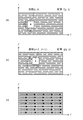
- N captured images located on the YZ plane (the plane formed by the exhaust gas flow direction and the vertical direction) are arranged along the X axis (front-rear direction).
- A1 to A8 in FIG. 5 correspond to A1 to A8 in FIG. 3, and an image captured in the range of A1 is referred to as a “first image”, and an image captured in the range of A2 is referred to as a “second image”.
- the first image, the eighth image, the second image, the seventh image, The third image, the sixth image, the fourth image, and the fifth image are arranged in this order.
- the n captured images arranged in this way represent the state of the exhaust gas in the entire interior of the laser introduction tube 20. Note that a plurality of white circles in FIG. 5 indicate tracers mixed in the exhaust gas.
- control calculation unit 90 is electrically connected to the absolute pressure gauges 60 and 60, the air-fuel ratio meter 70, and the temperature measurement unit 80, and the exhaust gas measured by the absolute pressure gauges 60 and 60.
- the flow rate measuring device 1 based on the absolute pressure Pm [kPa ⁇ abs] of the exhaust gas, the air-fuel ratio Rm of the exhaust gas measured by the air-fuel ratio meter 70, and the instantaneous temperature Tm [° C.] of the exhaust gas measured by the temperature measuring unit 80.
- the mass flow rate M [kg / s] of the exhaust gas is calculated.
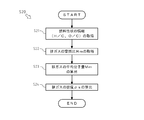
- step S1 the control calculation unit 90 acquires first to eighth images for two consecutive periods captured by the imaging unit 50, that is, a total of 16 captured images. Specifically, the control calculation unit 90 causes the imaging unit 50 to capture the first image to the eighth image during the cycle T [s], and then again the first image to the eighth image during the cycle T [s]. By causing the imaging unit 50 to capture images, first to eighth images for two periods are acquired. In the first image to the eighth image captured in this way, a time interval corresponding to the period T [s] is set between the image captured in the first period and the image captured in the second period. Will have. After obtaining the first image to the eighth image for two periods, the control calculation unit 90 shifts the control stage to step S2.
- step S2 the control calculation unit 90 performs a PIV (Particle Image Velocity) process on the first to eighth images for two cycles.
- PIV Particle Image Velocity
- the PIV processing is two captured images obtained by imaging a fluid (exhaust gas in the present embodiment) at a first time and a second time that are spaced apart from each other. This is a method for calculating the amount of movement of each fluid position by performing pattern matching. Note that the time interval between the first time and the second time in the present embodiment is a period T [s].
- the image captured at the first time is represented as f (y, z), and as shown in FIG. 7B, the time is later than the first time.
- an image captured at the second time is expressed as g (y, z), with respect to a range of m ⁇ n pixels centered on coordinates (y, z) in the image f (y, z), While shifting the range of m ⁇ n pixels centered on the coordinates (y, z) in the image g (y, z), the coordinates (y + ⁇ , z + ⁇ ) at which the cross-correlation coefficient R fg is maximized as shown in the following Equation 1. ).
- the black arrow shown in FIG.7 (c) represents the movement vector of the fluid.
- the flow rate measuring device 1 performs a PIV process different from the PIV process using the conventional cross-correlation method as described above. Below, the PIV process in the flow measuring device 1 is demonstrated.
- an image f (y, z) having a density distribution and an image g (y, z) having a density distribution are acquired.
- This can be realized by using cigarette or incense smoke as a tracer mixed in the fluid, instead of a substance generally used in PIV processing.
- what is necessary is just to mix in waste gas when step S1 in FIG. 6 is performed.
- FIG. 8A shows a grayscale image f (y, z).
- edge detection is performed on each of the grayscale image f (y, z) and the grayscale image g (y, z) using a Laplacian filter, and then binarization is performed.
- images obtained by extracting the contour lines of the light and shade in the light and shade image f (y, z) and the light and shade image g (y, z) (hereinafter referred to as “the contour image f (y, z)” and “the contour image g (y , Z) ”) is created.
- FIG. 8B shows a contour image f (y, z).
- the PIV process in the flow rate measuring apparatus 1 uses a logical operation as shown in Equation 2 above, and uses a logical operation such as the contour image f (y, z) and the contour line with a relatively small amount of information. Since it is performed on the image g (y, z), the time required for the PIV processing can be reduced. Therefore, a DSP or CPU for calculation with a relatively low processing speed can be applied to the control calculation unit 90 in the present embodiment, and the manufacturing cost of the flow rate measuring device 1 can be reduced.
- the PIV processing is favorably performed. It can be carried out.
- step S2 the control calculation unit 90 performs the PIV process on the first to eighth images for two cycles as described above.
- a movement vector of exhaust gas per T [s] can be obtained.
- black arrows on the first image to the eighth image in FIG. 9 represent the movement vector of the exhaust gas.
- the movement vectors of exhaust gas at the plurality of coordinates of the first image to the eighth image calculated in this way are not regular tracers, but are exhaust gas such as water droplets condensed with water vapor, unburned fuel, and engine oil.
- exhaust gas such as water droplets condensed with water vapor, unburned fuel, and engine oil.
- disurbing substance an error vector due to the contained substance
- the error vector is removed from the exhaust gas movement vector at the plurality of coordinates of the first image to the eighth image.
- a method for removing an error vector will be described.
- the difference between the tracer and the disturbance substance cannot be discriminated directly from the first image to the eighth image.
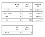
- particles (in this embodiment) contained in the fluid when the fluid (in this embodiment, exhaust gas) starts to flow from a stationary state has a relatively large difference in time constant ⁇ p (hereinafter referred to as “particle time constant ⁇ p ”) indicating the time until the speed of the tracer or disturbance substance reaches 63% of the speed of the fluid. Therefore, as described below, by using an event caused by the difference between the particle time constant ⁇ p of the tracer and the particle time constant ⁇ p of the disturbance substance, the exhaust gas at a plurality of coordinates in the first to eighth images is used. It is possible to remove the error vector from the movement vector.
- the particle time constant ⁇ p can be calculated using the following formula 3.
- the disturbance substance has a larger particle time constant ⁇ p than that of the tracer, the time required to reach a predetermined speed (flow rate of exhaust gas) increases and is calculated in the PIV process.
- the moving amount becomes smaller. Therefore, it is possible to determine a movement vector whose movement amount is a predetermined value or less as an error vector.
- the time for calculating the movement vector of the exhaust gas that is, the imaging time interval between the two images for which the PIV processing is performed is the period T [s]
- the movement of the tracer after the exhaust gas starts to flow from the stationary state. Since the difference between the amount and the amount of movement of the disturbing substance is relatively small, as shown in FIG. 12A, the distribution of the tracer and the distribution of the disturbing substance overlap, and it is difficult to determine a threshold for discriminating the error vector. It is. Therefore, as shown in FIG.
- the time for calculating the movement vector of the exhaust gas that is, the imaging time interval between the two images for which the PIV process is performed is a value smaller than the cycle T [s] (in this embodiment, T / 5 [s]), and the difference between the amount of movement of the tracer after the exhaust gas starts to flow from a stationary state and the amount of movement of the disturbance substance is relatively large.
- T [s] in this embodiment, T / 5 [s]
- This makes it possible to determine a threshold for determining an error vector, and to remove the error vector from a plurality of exhaust gas movement vectors.
- the arithmetic average of the median value of the movement amount in the tracer distribution and the median value of the movement amount in the disturbance substance distribution is employed as a threshold value for determining the error vector.
- the time for calculating the exhaust gas movement vector in determining the threshold for determining the error vector is T / 5 [s], but the present invention is not limited to this. A value that makes the difference between the amount of movement of the tracer and the amount of movement of the disturbance substance remarkable may be adopted.
- the PIV process with a period smaller than the period T [s] (T / 5 [s] in this embodiment) is performed. .
- a threshold value for determining an error vector from the distribution of the tracer and the distribution of the disturbance substance is determined.
- an error vector is determined from the determined threshold value, and the coordinates of the error vector are recorded.
- a movement vector that coincides with the coordinates of the error vector is removed from the movement vectors of the exhaust gas at a plurality of coordinates calculated by the normal PIV process (in the cycle T [s]).
- Such processing is performed on the first image to the eighth image, and error vectors existing in the first image to the eighth image are removed, thereby reducing errors due to the influence of disturbance substances in the PIV processing. Can do.
- the control calculation unit 90 shifts the control stage to step S3.
- step S ⁇ b> 3 the control calculation unit 90 averages the movement vector of the exhaust gas at a plurality of coordinates on the first image as one movement vector, and Y of the averaged one movement vector
- the component (the component in the flow direction of the exhaust gas) is calculated as the movement amount By1 [m], and similarly, the movement amount By2 [m] is calculated in the second image, and the movement amount By3 [m] is calculated in the third image.
- the movement amount By4 [m] is calculated in the fourth image, the movement amount By5 [m] is calculated in the fifth image, the movement amount By6 [m] is calculated in the sixth image, and the movement amount in the seventh image.
- By7 [m] is calculated, and a movement amount By8 [m] is calculated in the eighth image.
- the control calculation unit 90 shifts the control stage to step S4.
- step S4 the control calculation unit 90 calculates the arithmetic average of the movement amount By1 [m] to the movement amount By8 [m] as the representative movement amount B [m]. After calculating the representative movement amount B [m], the control calculation unit 90 shifts the control stage to step S5.
- step S5 the control calculation unit 90 calculates the flow velocity S [m / s] (hereinafter referred to as “actual flow velocity S [m / s]”) in the actual environment of the exhaust gas by using the following equation (4). To do. After calculating the actual flow rate S [m / s] of the exhaust gas, the control calculation unit 90 moves the control stage to step S6.
- step S ⁇ b> 6 the control calculation unit 90 uses the following equation 5 to calculate the flow rate Qm [m 3 / s] (hereinafter referred to as “actual flow rate Qm [m 3 / s]”) in the actual exhaust gas environment. Is calculated.
- a [m 2 ] in Formula 5 indicates a cross-sectional area along the direction perpendicular to the flow direction of the exhaust gas in the internal space of the laser introduction tube 20, that is, the exhaust gas flow path area.
- step S7 the control calculation unit 90 uses the following Equation 6 to calculate the volume flow rate Qs [m 3 / s] (hereinafter, “standard flow rate Qs [m 3 ] in the standard state of exhaust gas (20 ° C., 1 atm)). / S] ”). Since the actual flow rate Qm [m 3 / s] of the exhaust gas calculated in step S6 varies depending on the temperature and pressure, it is converted into a standard state and used as the standard flow rate Qs [m 3 / s]. Note that Pm [kPa ⁇ abs] in Equation 6 is the absolute pressure Pm [kPa ⁇ abs] of the exhaust gas measured by the absolute pressure gauges 60 and 60 as described above.
- the absolute pressure Pm [kPa ⁇ abs] of the exhaust gas is measured by the absolute pressure gauges 60 and 60 before the execution of step S7 (for example, in parallel with step S2). Further, Tm [° C.] in Equation 6 is the instantaneous temperature Tm [° C.] of the exhaust gas measured by the temperature measuring unit 80 as described above. As described above, the instantaneous temperature Tm [° C.] of the exhaust gas is not directly measured by the temperature measuring unit 80, but is measured by the pressure gauge 82 and the pressure of the exhaust gas flowing in the bypass 81 and the air It is calculated based on the fuel ratio Rm and the like. The calculation of the instantaneous temperature Tm [° C.] of the exhaust gas is performed before the execution of Step S7 (for example, in parallel with Step S2).
- the instantaneous temperature Tm [° C.] of the exhaust gas is calculated through an instantaneous temperature calculation step S10.
- steps S11 to S17 are sequentially performed.
- step S ⁇ b> 11 the control calculation unit 90 calculates the primary natural frequency fn [Hz] of the air column in the bypass 81. More specifically, FFT (Fast Fourier Transform) is performed on the pressure of the exhaust gas flowing in the bypass 81 measured by the pressure gauge 82, and the highest natural frequency fn of the air column in the bypass 81 is obtained by using the highest gain frequency. Extracted as [Hz]. After calculating the primary natural frequency fn [Hz], the control calculation unit 90 shifts the control stage to step S12.
- FFT Fast Fourier Transform
- step S12 the control calculation unit 90 calculates the speed of sound C [m / s] under the exhaust gas atmosphere. Specifically, the sound speed Cb [m / s] in the bypass 81 is calculated as shown in the following Expression 7 using the primary natural frequency fn [Hz] calculated in step S11, and then the sound speed Cb [m / s] is calculated. s] is used to calculate the sound velocity C [m / s] under the exhaust gas atmosphere as shown in the following equation (8). Note that L [m] in Equation 7 is the length of the bypass 81 in the longitudinal direction (exhaust gas flow direction). Further, d [m] in Equation 8 is the inner diameter of the bypass 81.
- control calculation unit 90 moves the control stage to step S13.
- step S ⁇ b> 13 the control calculation unit 90 performs H / C (atom ratio of hydrogen and carbon) and O / C (oxygen and carbon), which are property information of the fuel that is the source of the exhaust gas in the flow measurement device 1. Of atomic ratio). These pieces of information are determined in advance according to the type of fuel. After obtaining the air-fuel ratio Rm of the exhaust gas, the control calculation unit 90 shifts the control stage to step S14.
- H / C atom ratio of hydrogen and carbon
- O / C oxygen and carbon
- step S14 the control calculation unit 90 acquires the air-fuel ratio Rm of the exhaust gas measured by the air-fuel ratio meter 70. After obtaining the air-fuel ratio Rm of the exhaust gas, the control calculation unit 90 shifts the control stage to step S15.
- step S15 the control calculation unit 90 calculates the average molecular weight Mm [kg / mol of exhaust gas based on the molar fraction of each component (N 2 , O 2 , CO 2 , H 2 O, CO, H 2 ) of the exhaust gas. ] Is calculated.
- the molar fraction of each component (N 2 , O 2 , CO 2 , H 2 O, CO, H 2 ) of the exhaust gas which is necessary for calculating the average molecular weight Mm [kg / mol] of the exhaust gas.
- the molar fraction of each component of the exhaust gas is such that the air-fuel ratio Rm is greater than the stoichiometric air-fuel ratio R (when lean), the air-fuel ratio Rm is equal to the stoichiometric air-fuel ratio R, and the air-fuel ratio Rm is greater than the stoichiometric air-fuel ratio R.
- small (rich) it is calculated based on the reaction formula in each.
- the theoretical air-fuel ratio R is determined in advance depending on the type of fuel that is the source of the exhaust gas in the flow rate measuring device 1.
- the molar fraction of each component (N 2 , O 2 , CO 2 , H 2 O, CO, H 2 ) of the exhaust gas is calculated based on each reaction formula.
- the average molecular weight Mm [kg / mol] of the exhaust gas is calculated based on the molar fraction of each component (N 2 , O 2 , CO 2 , H 2 O, CO, H 2 ) of the exhaust gas calculated as described above. Is possible. Specifically, in each component of exhaust gas (N 2 , O 2 , CO 2 , H 2 O, CO, H 2 ), the molar fraction and the molar mass are integrated, and then the integrated values are totaled. Thus, the average molecular weight Mm [kg / mol] of the exhaust gas is calculated. After calculating the average molecular weight Mm [kg / mol] of the exhaust gas, the control calculation unit 90 moves the control stage to step S16.
- step S16 the control calculation unit 90 calculates the average specific heat ratio ⁇ of the exhaust gas.
- the average specific heat ratio ⁇ can be calculated as shown in Equation 12 below. Note that D2 in Equation 12 indicates the ratio of diatomic molecules such as CO, and D3 in Equation 12 indicates the ratio of triatomic molecules such as H 2 O, and can be calculated from the result of Step S15.
- control calculation unit 90 moves the control stage to step S17.
- step S ⁇ b> 17 the control calculation unit 90 calculates an instantaneous temperature Tm [° C.] of the exhaust gas. Specifically, first, the sound velocity C [m / s] calculated in step S12, the average molecular weight Mm [kg / mol] calculated in step S15, and the average specific heat ratio ⁇ calculated in step S16 are calculated.
- the absolute temperature Ta [K] of the exhaust gas is calculated as shown in the following formula 14 by converting the formula shown in the following formula 13 that is established using the formula. Thereafter, by converting the unit of the absolute temperature Ta [K] of the exhaust gas, the instantaneous temperature Tm [° C.] of the exhaust gas is calculated. Note that R in Equations 13 and 14 is a gas constant.
- the instantaneous temperature Tm [° C.] of the exhaust gas is calculated in the instantaneous temperature calculation step S10.
- the instantaneous temperature Tm [° C.] of the exhaust gas is difficult to directly measure with a high response with an existing thermometer, but there are many pressure gauges (for example, the pressure gauge 82) that respond on the order of several kHz. Therefore, it can be calculated with high accuracy by using the pressure.
- the advantage of calculating the instantaneous temperature Tm [° C.] of the exhaust gas based on the pressure is that even if the absolute accuracy of the pressure value is not good, if the pressure change, that is, the frequency in the air column vibration is accurate, The temperature can be accurately calculated. Therefore, the instantaneous temperature Tm [° C.] of the exhaust gas can be accurately calculated by calculating the instantaneous temperature Tm [° C.] of the exhaust gas in the instantaneous temperature calculation step S10.
- control calculation unit 90 uses the absolute pressure Pm [kPa ⁇ abs] of the exhaust gas and the instantaneous temperature Tm [° C.] of the exhaust gas, and the standard flow rate Qs [ After calculating m 3 / s], the control stage proceeds to step S8.
- step S8 the control calculation unit 90 calculates the mass flow rate M [kg / s] of the exhaust gas using the following formula 15.
- ⁇ s [kg / m 3 ] in Equation 15 is the density ⁇ s [kg / m 3 ] of the exhaust gas.
- the density ⁇ s [kg / m 3 ] of the exhaust gas is calculated based on the average molecular weight Mm [kg / mol] of the exhaust gas.
- the calculation of the average molecular weight Mm [kg / mol] of the exhaust gas is performed before the execution of Step S7 (for example, in parallel with Step S2).
- the calculation method of the density ⁇ s [kg / m 3 ] of the exhaust gas will be described in detail.
- the density ⁇ s [kg / m 3 ] of the exhaust gas is calculated through the density calculation step S20.
- steps S21 to S24 are sequentially performed.
- Steps S21 to S23 are the same as steps S13 to S15 (see FIG. 14) of the instantaneous temperature calculation step S10, respectively, and thus description thereof is omitted.
- the instantaneous temperature calculation step S10 is performed prior to the density calculation step S20, the results of steps S13 to S15 can be employed without separately performing steps S21 to S23. .
- step S24 the control calculation unit 90 calculates the exhaust gas density ⁇ s [kg / m 3 ].
- the density ⁇ s [kg / m 3 ] is calculated from the gas equation of state using the average molecular weight Mm [kg / mol] as shown in the following equation (16). Note that R in Equation 16 is a gas constant.
- the density ⁇ s [kg / m 3 ] of the exhaust gas is calculated.
- the density ⁇ s [kg / m 3 ] of the exhaust gas is calculated using the fuel property information (H / C, O / C) and the air-fuel ratio Rm in the actual operation region. Thereby, the density ⁇ s [kg / m 3 ] of the exhaust gas can be calculated with high accuracy.
- control calculation unit 90 uses the exhaust gas density ⁇ s [kg / m 3 ] and the exhaust gas standard flow rate Qs [m 3 / s] calculated in the density calculation step S20, and the above equation 15 As described above, the mass flow rate M [kg / s] of the exhaust gas is calculated.
- the above processing is repeatedly performed, and the calculation of the gas mass flow rate M [kg / s] by the control calculation unit 90 is performed in real time.
- the flow rate measuring device 1 is a device that measures the mass flow rate M [kg / s] of exhaust gas discharged from an engine provided in an automobile or the like, and introduces a laser in which the exhaust gas flows inside together with a tracer.
- the tube 20, the irradiation unit 30 for irradiating the beam-shaped laser, and the sheet-shaped laser beam that cuts the internal space of the laser introduction tube 20 along the flow direction of the exhaust gas.
- the laser distributor 40 that reflects the laser in the forward and backward directions and the sheet distributor formed by the laser distributor 40.
- the first to eighth images are captured at a fixed time interval during T [s], and the control calculation unit 90 captures the first to eighth images for two consecutive cycles from the imaging unit 50.
- the exhaust gas movement vector at The Y components (components in the flow direction of the exhaust gas) of the averaged one movement vector in the images to the eighth image are the exhaust gas movement amount By1 [m] to the movement amount By8 [m], respectively, and the exhaust gas movement amount By1 [ m] to the amount of movement By8 [m] is defined as a representative movement amount B [m] of the exhaust gas, and the actual flow velocity S [m / s] of the exhaust gas is calculated from the representative movement amount B [m] of the exhaust gas.
- the actual flow rate Qm [m 3 / s] of the exhaust gas is calculated from the actual flow velocity S [m / s], and the mass flow rate M [kg / s] of the exhaust gas is calculated based on the actual flow rate Qm [m 3 / s] of the exhaust gas. calculate. Thereby, even when the flow of the exhaust gas in the laser introduction tube 20 is biased or pulsated, the mass flow rate M [kg / s] of the exhaust gas can be accurately measured.
- control calculation unit 90 calculates exhaust gas movement vectors at a plurality of coordinates on each image, which are calculated at a time interval smaller than the cycle T [s] (T / 5 [s] in the present embodiment).
- the error vector is removed from the movement vector of the exhaust gas at a plurality of coordinates on each image calculated at a time interval of the period T [s].
- control calculation unit 90 extracts the contour lines of the exhaust gas in the first to eighth images for two consecutive cycles, and the first image for two consecutive cycles in which the contour lines of the exhaust gas are extracted. Based on the eighth image, exhaust gas movement vectors at a plurality of coordinates on each image are calculated. As a result, the time required for the PIV process can be shortened. Therefore, a DSP or CPU for calculation with a relatively low processing speed can be applied to the control calculation unit 90, and the manufacturing cost of the flow rate measuring device 1 can be reduced. Also, even when the sizes of the first image to the eighth image are so large that the conventional PIV processing cannot keep up, the PIV processing can be performed satisfactorily.
- both ends of the absolute pressure gauges 60 and 60 for measuring the absolute pressure Pm [kPa ⁇ abs] of the exhaust gas flowing in the laser introduction tube 20 and the inside of the laser introduction tube 20 are communicated with the laser introduction tube 20.
- a tubular bypass 81 to be attached and a pressure gauge 82 for measuring the pressure of the exhaust gas flowing in the bypass 81 are further provided, and the control calculation unit 90 is an exhaust gas flowing in the bypass 81 measured by the pressure gauge 82.
- the primary natural frequency fn [Hz] of the air column in the bypass 81 is calculated based on the pressure of the air column, and the sound velocity Cb [m / h] in the bypass 81 is calculated from the primary natural frequency fn [Hz] of the air column in the bypass 81.
- the sound velocity C [m / s] in the exhaust gas atmosphere is calculated from the sound velocity Cb [m / s] in the bypass 81.
- the instantaneous temperature Tm [° C.] of gas is calculated with high accuracy
- the mass flow rate M [kg / s] of the exhaust gas can be measured with high accuracy.
- an air-fuel ratio meter 70 for measuring the air-fuel ratio Rm of the exhaust gas flowing in the laser introduction pipe 20 is further provided, and the control calculation unit 90 includes the air-fuel ratio Rm of the exhaust gas and the property information of the fuel that is the source of the exhaust gas.
- the control calculation unit 90 includes the air-fuel ratio Rm of the exhaust gas and the property information of the fuel that is the source of the exhaust gas.
- the present invention can be used for a flow rate measuring device that measures the mass flow rate of a fluid by PIV processing.
Abstract
Description
これは、排ガスが(1)ガス成分以外の物質(水蒸気が凝縮した水滴、未燃燃料、及びエンジンオイル等)を含み、(2)温度、及びエンジンの回転数の変化等による流速の変動幅が大きく、(3)エンジンの回転数及び気筒数に比例した圧力脈動を含み、(4)排気管の湾曲部等の影響によって流れに偏りが生じる、という特性を有しており、これら(1)~(4)に示す排ガスの特性により、上記の流量計測装置では精度良く排ガスの質量流量を計測することができないためである。
特許文献1に記載の装置は、微少な時間間隔を空けた二つの時刻において、流体が流動するダクト内にシート状のレーザを照射すると同時に、シート状のレーザによる、ダクトの内部空間の切断面の画像を撮像し、当該二つの時刻における撮像画像に基づいて、流体の粒子の移動量を算出する。このように算出された流体の粒子の移動量を用いることで、ダクト内を流動する流体の質量流量を算出することができる。
流量計測装置1は、自動車等に設けられたエンジンから排出される排ガスの流量(厳密には、質量流量M[kg/s])を計測する装置である。
なお、図1における矢印Yの指す方向を排ガスの流動方向とし、排ガスの流動方向における上流側を単に「上流側」、排ガスの流動方向における下流側を単に「下流側」と記す。
また、図1における矢印Xの指す方向を流量計測装置1の後方向として前後方向を規定し、図1における矢印Zの指す方向を流量計測装置1の上方向として上下方向を規定する。
ここで、トレーサとは、排ガスを可視化するために用いられる粒子状の物質である。通常、排ガスを直接撮像することはできないが、トレーサが混入された排ガスにレーザ等が照射されると、トレーサによるミー散乱が生じて散乱光が発生するため、排ガスにトレーサを混入することで、トレーサを排ガスとして可視化して、排ガスの撮像を行うことが可能となる。
トレーサ分配器11は、所定量のトレーサを貯留する部材であり、トレーサ導入管10の内部にトレーサを供給する。
こうして、排気管E1からトレーサ導入管10へと流入した排ガスは、トレーサ導入管10においてトレーサが混入され、レーザ導入管20へと流動した後、排気管E2に流出することとなる。
なお、レーザ導入窓21は、レーザ分配器40によって形成されたシート状のレーザをレーザ導入管20の内部に導入可能な透過性を有する素材からなり、レーザ導入管20の上面において、レーザ導入管20の外周面から内周面にかけて形成されている。
なお、撮像用窓22は、レーザ導入管20の内部をレーザ導入管20の外部から撮像可能とするための透明な部材であり、レーザ導入管20の前面において、レーザ導入管20の外周面から内周面にかけて形成されている。
図3に示す位置P1をレーザ分配器40の初期位置とすると、レーザ分配器40が位置P2まで回動し、再び位置P1に戻るまで(一往復)がレーザ分配器40の1周期(「周期T[s]」と規定する)となっている。換言すれば、レーザ分配器40によって反射されたシート状のレーザがレーザ導入管20内の前後方向における全範囲にて一往復する時間が周期T[s]となっている。
このようにレーザ分配器40が揺動することで、排ガスの流動方向に沿って延出するシート状のレーザの照射位置が推移し、当該レーザがT/2[s]で、レーザ導入管20内の前後方向における全範囲において分配されることとなる。
詳細には、撮像部50は、その撮像時間(シャッタの開き時間)をT/n[s]の50%(T/2n[s])として、t0からT/2n[s]経過するまで撮像を行い(図3(a)におけるA1の範囲参照)、t1からT/2n[s]経過するまで撮像を行い(図3(a)におけるA2の範囲参照)、t2からT/2n[s]経過するまで撮像を行い(図3(a)におけるA3の範囲参照)、t3からT/2n[s]経過するまで撮像を行い(図3(a)におけるA4の範囲参照)、t4からT/2n[s]経過するまで撮像を行い(図3(b)におけるA5の範囲参照)、t5からT/2n[s]経過するまで撮像を行い(図3(b)におけるA6の範囲参照)、t6からT/2n[s]経過するまで撮像を行い(図3(b)におけるA7の範囲参照)、t7からT/2n[s]経過するまで撮像を行う(図3(b)におけるA8の範囲参照)。
図4によれば、撮像部50のシャッタは、t0からT/2n[s]経過するまでの間、t1からT/2n[s]経過するまでの間、t2からT/2n[s]経過するまでの間、t3からT/2n[s]経過するまでの間、t4からT/2n[s]経過するまでの間、t5からT/2n[s]経過するまでの間、t6からT/2n[s]経過するまでの間、及びt7からT/2n[s]経過するまでの間において開き、その他の時間においては閉じている。
これにより、レーザ導入管20内の前後方向における異なる位置での排ガスの流れを把握しつつ、レーザ導入管20の内部全体を撮像することができる。
なお、本実施形態においては、撮像部50による各撮像画像の撮像時間を1周期をn等分した時間の半分、つまりT/2n[s]としたが、これに限定するものではなく、1周期をn等分した時間よりも短い時間であればよい。
YZ平面(排ガスの流動方向と上下方向とが成す面)上に位置する撮像画像が、X軸(前後方向)に沿ってn個配置されている。図5におけるA1~A8は図3におけるA1~A8に対応しており、A1の範囲で撮像された画像を「第1画像」とし、A2の範囲で撮像された画像を「第2画像」とし、以下同様に「第8画像」までを定義し、レーザ導入管20内における前後方向の位置を考慮すると、後方向に向かうに従って、第1画像、第8画像、第2画像、第7画像、第3画像、第6画像、第4画像、第5画像の順に配置される。このように配置されたn個の撮像画像は、レーザ導入管20の内部全体における排ガスの状態を表すこととなる。
なお、図5における複数の白塗りの円は、排ガスに混入されたトレーサを示している。
詳細には、制御演算部90は、周期T[s]の間に第1画像~第8画像を撮像部50に撮像させた後、再度周期T[s]の間に第1画像~第8画像を撮像部50に撮像させることにより、2周期分の第1画像~第8画像を取得する。
このように撮像された第1画像~第8画像においては、1周期目に撮像された画像と、2周期目に撮像された画像との間に、それぞれ周期T[s]分の時間間隔を有することとなる。
制御演算部90は、2周期分の第1画像~第8画像を取得した後、制御段階をステップS2に移行する。
図7(a)に示すように、第一の時刻において撮像された画像をf(y,z)と表し、図7(b)に示すように、第一の時刻よりも後の時刻である第二の時刻において撮像された画像をg(y,z)と表した場合に、画像f(y,z)における座標(y,z)を中心とするm×nピクセルの範囲に対して、画像g(y,z)における座標(y,z)を中心とするm×nピクセルの範囲をずらしつつ、下記の数1の如く、相互相関係数Rfgが最大となる座標(y+ξ,z+η)を抽出する。
これを繰り返すことで、図7(c)に示すように、第一の時刻から第二の時刻までの流体の移動量を算出することができる。なお、図7(c)に示す黒塗り矢印は、流体の移動ベクトルを表している。

なお、本実施形態においては、図6におけるステップS1が行われる際に、排ガスに混入させればよい。
図8(a)に濃淡画像f(y,z)を示す。
図8(b)に等高線画像f(y,z)を示す。

したがって、本実施形態における制御演算部90に、比較的処理速度の低い演算用のDSP又はCPUを適用することができ、流量計測装置1の製造コストを低減することができる。
また、PIV処理に用いられる画像(画像f(y,z)、及び画像g(y,z))のサイズが従来のPIV処理では間に合わない程度に大きい場合であっても、良好にPIV処理を行うことができる。
こうして、図9に示すように、互いに周期T[s]分の時間間隔を有する2周期分の第1画像~第8画像から、第1画像~第8画像に分布する、複数の座標における周期T[s]あたりの排ガスの移動ベクトルを得ることができる。なお、図9における第1画像~第8画像上の黒塗り矢印は、排ガスの移動ベクトルを表している。
なお、粒子時定数τpは、下記の数3を用いて算出可能である。

そこで、図11に示すように、排ガスの移動ベクトルを算出するための時間、つまりPIV処理が行われる2画像間の撮像時間間隔を周期T[s]よりも小さい値(本実施形態においては、T/5[s])とし、排ガスが静止状態から流動し始めてからのトレーサの移動量と外乱物質の移動量との差を比較的大きくすることで、図12(b)の如く、トレーサの分布と外乱物質の分布とを分離させる。
これにより、過誤ベクトルを判別するための閾値を決定することが可能となり、排ガスの複数の移動ベクトルから過誤ベクトルを除去することができる。
なお、本実施形態においては、トレーサの分布における移動量の中央値と、外乱物質の分布における移動量の中央値との算術平均が過誤ベクトルを判別するための閾値として採用される。
また、本実施形態においては、過誤ベクトルを判別するための閾値を決定する際における、排ガスの移動ベクトルを算出するための時間をT/5[s]としたが、これに限定するものではなく、トレーサの移動量と外乱物質の移動量との差が顕著となる値を採用すればよい。
第一に、通常の(周期T[s]での)PIV処理とは別に、周期T[s]よりも小さい周期(本実施形態においては、T/5[s])でのPIV処理を行う。
第二に、トレーサの分布、及び外乱物質の分布から過誤ベクトルを判別するための閾値を決定する。
第三に、決定された閾値より過誤ベクトルを判別し、当該過誤ベクトルの座標を記録する。
第四に、図13の如く、通常の(周期T[s]での)PIV処理により算出された複数の座標における排ガスの移動ベクトルから、過誤ベクトルの座標と一致する移動ベクトルを除去する。
制御演算部90は、過誤ベクトルの除去を含むPIV処理を行った後、制御段階をステップS3に移行する。
制御演算部90は、移動量By1[m]~移動量By8[m]を算出した後、制御段階をステップS4に移行する。
制御演算部90は、代表移動量B[m]を算出した後、制御段階をステップS5に移行する。
制御演算部90は、排ガスの実流速S[m/s]を算出した後、制御段階をステップS6に移行する。

なお、数5におけるA[m2]は、排ガスの流路面積、つまりレーザ導入管20の内部空間における排ガスの流動方向に直交する方向に沿った断面積を示している。
制御演算部90は、排ガスの実流量Qm[m3/s]を算出した後、制御段階をステップS7に移行する。

ステップS6において算出された排ガスの実流量Qm[m3/s]は、温度及び圧力に応じて値が変化するため、標準状態に換算され、スタンダード流量Qs[m3/s]として用いられる。
なお、数6におけるPm[kPa・abs]は、前述のように、絶対圧計60・60によって計測される排ガスの絶対圧Pm[kPa・abs]である。絶対圧計60・60による排ガスの絶対圧Pm[kPa・abs]の計測は、ステップS7の実施前に(例えば、ステップS2と並行に)行われる。
また、数6におけるTm[℃]は、前述のように、温度計測部80によって計測される排ガスの瞬時温度Tm[℃]である。排ガスの瞬時温度Tm[℃]は、前述のように、温度計測部80によって直接的に計測されるものではなく、圧力計82によって計測された、バイパス81内を流動する排ガスの圧力、及び空燃比Rm等に基づいて算出される。排ガスの瞬時温度Tm[℃]の算出は、ステップS7の実施前に(例えば、ステップS2と並行に)行われる。

図14に示すように、排ガスの瞬時温度Tm[℃]は、瞬時温度算出工程S10を経て算出される。
瞬時温度算出工程S10においては、ステップS11~ステップS17が順次行われる。
詳細には、圧力計82によって計測されたバイパス81内を流動する排ガスの圧力に対してFFT(高速フーリエ変換)を行い、ゲインの一番高い周波数をバイパス81における気柱の一次固有振動数fn[Hz]として抽出する。
制御演算部90は、一次固有振動数fn[Hz]を算出した後、制御段階をステップS12に移行する。
詳細には、ステップS11にて算出された一次固有振動数fn[Hz]を用いて、バイパス81内における音速Cb[m/s]を下記の数7の如く算出した後、音速Cb[m/s]を用いて、排ガス雰囲気下での音速C[m/s]を下記の数8の如く算出する。
なお、数7におけるL[m]は、バイパス81の長手方向(排ガスの流動方向)の長さである。
また、数8におけるd[m]は、バイパス81の内径である。


制御演算部90は、排ガスの空燃比Rmを取得した後、制御段階をステップS14に移行する。
制御演算部90は、排ガスの空燃比Rmを取得した後、制御段階をステップS15に移行する。
排ガスの各成分のモル分率は、空燃比Rmが理論空燃比Rよりも大きい場合(リーン時)、空燃比Rmが理論空燃比Rに等しい場合、及び空燃比Rmが理論空燃比Rよりも小さい場合(リッチ時)、それぞれにおける反応式に基づいて算出される。
なお、理論空燃比Rは、流量計測装置1における排ガスの元となった燃料の種類によって予め決定されているものである。
この時、φ=R/Rm、n=yが成立し、未知数φ、nが算出される。

この時、φ=1、n=(1+0.25y-0.5zφ)/0.2099が成立し、未知数φ、nが算出される。

この時、φ=a+b、1+n/4=a+b/2+c/2、nφ=2c+2d、bc/ad=Kが成立し、未知数a、b、c、d、φ、nが算出される。なお、Kは平衡定数である。

詳細には、排ガスの各成分(N2、O2、CO2、H2O、CO、H2)において、そのモル分率とモル質量との積算を行った後、それらの積算値を合計することで、排ガスの平均分子量Mm[kg/mol]が算出される。
制御演算部90は、排ガスの平均分子量Mm[kg/mol]を算出した後、制御段階をステップS16に移行する。
平均比熱比κは、下記の数12の如く算出可能である。
なお、数12におけるD2は、CO等の2原子分子の割合を示し、数12におけるD3は、H2O等の3原子分子の割合を示しており、ステップS15の結果により算出可能である。

詳細には、まず、ステップS12にて算出された音速C[m/s]、ステップS15にて算出された平均分子量Mm[kg/mol]、及びステップS16にて算出された平均比熱比κを用いて成立する下記の数13に示す式を変換することにより、排ガスの絶対温度Ta[K]を下記の数14の如く算出する。その後、排ガスの絶対温度Ta[K]の単位を変換することにより、排ガスの瞬時温度Tm[℃]が算出されることとなる。なお、数13及び数14におけるRは、気体定数である。


排ガスの瞬時温度Tm[℃]は、既存の温度計では、高応答で直接的に計測することが困難であるが、数kHzオーダで応答する圧力計(例えば、圧力計82)が多数存在するため、圧力を用いることで、高精度に算出することができる。このように、圧力に基づいて、排ガスの瞬時温度Tm[℃]を算出する利点は、圧力の値の絶対精度は良好でなくとも、圧力変化、つまり気柱振動における周波数が正確であれば、温度を精度良く算出することができる点である。したがって、瞬時温度算出工程S10にて排ガスの瞬時温度Tm[℃]を算出することにより、排ガスの瞬時温度Tm[℃]を精度良く算出することができる。
なお、数15におけるρs[kg/m3]は、排ガスの密度ρs[kg/m3]である。排ガスの密度ρs[kg/m3]は、排ガスの平均分子量Mm[kg/mol]に基づいて算出される。排ガスの平均分子量Mm[kg/mol]の算出は、ステップS7の実施前に(例えば、ステップS2と並行に)行われる。

図15に示すように、排ガスの密度ρs[kg/m3]は、密度算出工程S20を経て算出される。
密度算出工程S20においては、ステップS21~ステップS24が順次行われる。
なお、瞬時温度算出工程S10が密度算出工程S20よりも先に行われている場合においては、ステップS21~ステップS23を別途行うことなく、ステップS13~ステップS15の結果を採用することが可能である。
密度ρs[kg/m3]は、平均分子量Mm[kg/mol]を用いて、気体の状態方程式から、下記の数16の如く算出される。なお、数16におけるRは、気体定数である。

上記のように、排ガスの密度ρs[kg/m3]は、燃料性状の情報(H/C、O/C)、及び実運転領域の空燃比Rmを用いて算出される。
これにより、排ガスの密度ρs[kg/m3]を精度良く算出することができる。
これにより、レーザ導入管20内における排ガスの流れに偏り、又は脈動が生じている場合でも、排ガスの質量流量M[kg/s]を精度良く計測できる。
これにより、排ガスの移動量By1[m]~移動量By8[m]を精度良く算出することができ、延いては排ガスの質量流量M[kg/s]を精度良く計測できる。
これにより、PIV処理に要する時間を短縮することができる。したがって、制御演算部90に、比較的処理速度の低い演算用のDSP又はCPUを適用することができ、流量計測装置1の製造コストを低減することができる。
また、第1画像~第8画像のサイズが従来のPIV処理では間に合わない程度に大きい場合であっても、良好にPIV処理を行うことができる。
これにより、排ガスの瞬時温度Tm[℃]を精度良く算出することができ、延いては排ガスの質量流量M[kg/s]を精度良く計測できる。
これにより、排ガスの密度ρs[kg/m3]を精度良く算出することができ、延いては排ガスの質量流量M[kg/s]を精度良く計測できる。
10 トレーサ導入管
20 レーザ導入管
30 照射部
40 レーザ分配器
50 撮像部
60 絶対圧計
70 空燃比計
80 温度計測部
81 バイパス
82 圧力計
90 制御演算部
Claims (6)
- エンジンから排出される排ガスの質量流量を計測する流量計測装置であって、
前記排ガスがトレーサと共に内部を流動するダクトと、
レーザを照射する照射部と、
前記照射部から照射されるレーザを、前記排ガスの流動方向に沿って前記ダクトの内部空間を切断するようなシート状のレーザとして反射させると共に、当該シート状のレーザを、前記排ガスの流動方向に直交する方向に沿って推移させるレーザ分配器と、
前記レーザ分配器によって形成されたシート状のレーザによる、前記ダクトの内部空間の切断面の画像を撮像する撮像部と、
前記排ガスの質量流量を算出する制御演算部と、を具備し、
前記レーザ分配器は、前記シート状のレーザを、その推移する方向に沿った、前記ダクト内の全範囲にて一往復させ、
前記撮像部は、前記シート状のレーザが前記ダクト内を一往復する時間を1周期として、1周期を複数等分した時間と、撮像のタイミングとを同期させ、かつ撮像時間を1周期を複数等分した時間より短い時間として、1周期の間に一定の時間間隔を空けて複数の画像を撮像し、
前記制御演算部は、
連続する2周期分の前記複数の画像を前記撮像部から取得し、
連続する2周期分の前記複数の画像に基づいて、各画像上の複数の座標における1周期あたりの前記排ガスの移動ベクトルを算出し、
各画像上の複数の座標における前記排ガスの移動ベクトルを一つの移動ベクトルとして平均化し、
各画像上の平均化された一つの移動ベクトルにおける、前記排ガスの流動方向の成分を前記排ガスの移動量とし、
前記複数の画像における前記排ガスの移動量の算術平均を前記排ガスの代表移動量とし、
前記排ガスの代表移動量から前記排ガスの実流速を算出し、
前記排ガスの実流速から前記排ガスの実流量を算出し、
前記排ガスの実流量に基づいて、前記排ガスの質量流量を算出する、
ことを特徴とする流量計測装置。 - 前記撮像部による各画像の撮像時間は、1周期を複数等分した時間の半分である、
ことを特徴とする請求項1に記載の流量計測装置。 - 前記制御演算部は、
1周期よりも小さい時間間隔において算出された、各画像上の複数の座標における前記排ガスの移動ベクトルを用いて、1周期分の時間間隔において算出された、各画像上の複数の座標における前記排ガスの移動ベクトルから過誤ベクトルを除去する、
ことを特徴とする請求項1又は請求項2に記載の流量計測装置。 - 前記制御演算部は、
連続する2周期分の前記複数の画像における前記排ガスの濃淡の等高線を抽出し、
前記排ガスの濃淡の等高線が抽出された、連続する2周期分の前記複数の画像に基づいて、各画像上の複数の座標における前記排ガスの移動ベクトルを算出する、
ことを特徴とする請求項1乃至請求項3のいずれか一項に記載の流量計測装置。 - 前記ダクト内を流動する前記排ガスの絶対圧を計測する絶対圧計と、
前記ダクトの内部と連通するように、両端部が前記ダクトに取り付けられる管状のバイパスと、
前記バイパス内を流動する前記排ガスの圧力を計測する圧力計と、を更に具備し、
前記制御演算部は、
前記圧力計によって計測された前記バイパス内を流動する前記排ガスの圧力に基づいて、前記バイパス内の気柱の一次固有振動数を算出し、
前記バイパス内の気柱の一次固有振動数から前記バイパス内における音速を算出し、
前記バイパス内における音速から前記排ガス雰囲気下での音速を算出し、
前記排ガス雰囲気下での音速に基づいて、前記排ガスの瞬時温度を算出し、
前記排ガスの瞬時温度、前記排ガスの絶対圧、及び前記排ガスの実流量から前記排ガスの標準状態での体積流量を算出し、
前記排ガスの標準状態での体積流量に基づいて、前記排ガスの質量流量を算出する、
ことを特徴とする請求項1乃至請求項4のいずれか一項に記載の流量計測装置。 - 前記ダクト内を流動する前記排ガスの空燃比を計測する空燃比計を更に具備し、
前記制御演算部は、
前記排ガスの空燃比、及び前記排ガスの元となった燃料の性状に基づいて、前記排ガスの平均分子量を算出し、
前記排ガスの平均分子量から前記排ガスの密度を算出し、
前記排ガスの密度に基づいて、前記排ガスの質量流量を算出する、
ことを特徴とする請求項1乃至請求項5のいずれか一項に記載の流量計測装置。
Priority Applications (5)
| Application Number | Priority Date | Filing Date | Title |
|---|---|---|---|
| EP11861159.9A EP2687829A4 (en) | 2011-03-15 | 2011-03-15 | THROUGHPUT MEASURING DEVICE |
| CN201180069302.9A CN103443594B (zh) | 2011-03-15 | 2011-03-15 | 流量计测装置 |
| JP2013504445A JP5729463B2 (ja) | 2011-03-15 | 2011-03-15 | 流量計測装置 |
| PCT/JP2011/056104 WO2012124062A1 (ja) | 2011-03-15 | 2011-03-15 | 流量計測装置 |
| US14/004,692 US9562797B2 (en) | 2011-03-15 | 2011-03-15 | Flow rate measuring apparatus |
Applications Claiming Priority (1)
| Application Number | Priority Date | Filing Date | Title |
|---|---|---|---|
| PCT/JP2011/056104 WO2012124062A1 (ja) | 2011-03-15 | 2011-03-15 | 流量計測装置 |
Publications (1)
| Publication Number | Publication Date |
|---|---|
| WO2012124062A1 true WO2012124062A1 (ja) | 2012-09-20 |
Family
ID=46830191
Family Applications (1)
| Application Number | Title | Priority Date | Filing Date |
|---|---|---|---|
| PCT/JP2011/056104 WO2012124062A1 (ja) | 2011-03-15 | 2011-03-15 | 流量計測装置 |
Country Status (5)
| Country | Link |
|---|---|
| US (1) | US9562797B2 (ja) |
| EP (1) | EP2687829A4 (ja) |
| JP (1) | JP5729463B2 (ja) |
| CN (1) | CN103443594B (ja) |
| WO (1) | WO2012124062A1 (ja) |
Cited By (5)
| Publication number | Priority date | Publication date | Assignee | Title |
|---|---|---|---|---|
| CN102928615A (zh) * | 2012-11-14 | 2013-02-13 | 中国兵器工业计算机应用技术研究所 | 一种航行中喷水推进器的喷口流速的测量方法 |
| JP2015010908A (ja) * | 2013-06-28 | 2015-01-19 | 国立大学法人山梨大学 | 非接触流体速度計測方法及び装置 |
| EP2837807A1 (en) * | 2013-08-12 | 2015-02-18 | Horiba, Ltd. | Fuel consumption calculation unit and fuel consumption calculation program |
| JP2016057084A (ja) * | 2014-09-05 | 2016-04-21 | 株式会社ジェイテクト | 流速計測方法 |
| JP2017111140A (ja) * | 2015-12-15 | 2017-06-22 | 株式会社堀場製作所 | 流量測定装置、燃費測定装置、流量測定装置用プログラム、及び流量測定方法 |
Families Citing this family (7)
| Publication number | Priority date | Publication date | Assignee | Title |
|---|---|---|---|---|
| CN103940481A (zh) * | 2014-05-14 | 2014-07-23 | 胡达广 | 激光微流量检测装置 |
| EP3106747A1 (en) * | 2015-06-15 | 2016-12-21 | Improbed AB | Control method for the operation of a combustion boiler |
| WO2017062848A1 (en) * | 2015-10-07 | 2017-04-13 | Cummins Inc. | Systems and methods for estimating fuel type and fuel properties using sonic speed |
| DE102017209127A1 (de) * | 2017-05-31 | 2018-12-06 | Robert Bosch Gmbh | Verfahren zum Berechnen eines Massenstroms von einem Tankentlüftungssystem in ein Saugrohr eines Verbrennungsmotors |
| CN109387256B (zh) * | 2017-08-08 | 2020-08-04 | 中国石油化工股份有限公司 | 一种输油管道容积核算方法及装置 |
| CN108981829A (zh) * | 2018-05-03 | 2018-12-11 | 中国石油大学(华东) | 一种基于悬臂梁变形挠度的油滴流量计装置及其计量方法 |
| CN109084914B (zh) * | 2018-09-17 | 2020-07-28 | 上海交通大学 | 一种高温高速湍流热通量的全场测量系统及方法 |
Citations (4)
| Publication number | Priority date | Publication date | Assignee | Title |
|---|---|---|---|---|
| JPS6129729A (ja) * | 1984-07-20 | 1986-02-10 | Tokyo Daigaku | 乱流可視化装置および方法 |
| JPS6319507A (ja) * | 1986-07-12 | 1988-01-27 | Diesel Kiki Co Ltd | 噴霧流測定装置 |
| JP2007285808A (ja) * | 2006-04-14 | 2007-11-01 | Kansai Electric Power Co Inc:The | 流体可視化計測装置 |
| JP2008215999A (ja) | 2007-03-02 | 2008-09-18 | Tokyo Electric Power Co Inc:The | 流体計測システム、流体計測方法およびコンピュータプログラム |
Family Cites Families (10)
| Publication number | Priority date | Publication date | Assignee | Title |
|---|---|---|---|---|
| JPH03157978A (ja) | 1989-11-15 | 1991-07-05 | Nec Corp | 光半導体装置 |
| DE19702849C2 (de) * | 1997-01-27 | 2000-05-18 | Deutsch Zentr Luft & Raumfahrt | Verfahren zum Erfassen der Massenstromverteilung einer Strömung über eine Ebene |
| AU2003253497A1 (en) * | 2002-07-05 | 2004-01-23 | Stichting Voor De Technische Wetenschappen | Two-point ensemble correlation method for piv applications |
| JP2004333276A (ja) | 2003-05-07 | 2004-11-25 | Fuji Xerox Co Ltd | 流体計測装置 |
| JP2005121439A (ja) | 2003-10-15 | 2005-05-12 | Horiba Ltd | 排ガス流量計測方法およびその装置 |
| DE602005008361D1 (de) * | 2005-01-31 | 2008-09-04 | Maillefer Sa | Vorrichtung zur Messung des Massedurchflusses eines partikelförmigen Materials |
| CN100437046C (zh) * | 2006-11-30 | 2008-11-26 | 天津大学 | 基于截面测量的气液两相流测量方法及装置 |
| DE102007034152B4 (de) * | 2007-07-21 | 2009-06-04 | Deutsches Zentrum für Luft- und Raumfahrt e.V. | Verfahren zur Messung einer Partikelströmung nach der Particle Image Velocimetry-Methode (PIV) |
| JP2009264772A (ja) | 2008-04-22 | 2009-11-12 | Nikon Corp | 流れ評価装置および流れ評価方法 |
| CN101975801B (zh) * | 2010-09-30 | 2012-12-26 | 北京交通大学 | 一种新型的多模态自适应传感器系统 |
-
2011
- 2011-03-15 WO PCT/JP2011/056104 patent/WO2012124062A1/ja active Application Filing
- 2011-03-15 CN CN201180069302.9A patent/CN103443594B/zh not_active Expired - Fee Related
- 2011-03-15 JP JP2013504445A patent/JP5729463B2/ja not_active Expired - Fee Related
- 2011-03-15 US US14/004,692 patent/US9562797B2/en not_active Expired - Fee Related
- 2011-03-15 EP EP11861159.9A patent/EP2687829A4/en not_active Withdrawn
Patent Citations (4)
| Publication number | Priority date | Publication date | Assignee | Title |
|---|---|---|---|---|
| JPS6129729A (ja) * | 1984-07-20 | 1986-02-10 | Tokyo Daigaku | 乱流可視化装置および方法 |
| JPS6319507A (ja) * | 1986-07-12 | 1988-01-27 | Diesel Kiki Co Ltd | 噴霧流測定装置 |
| JP2007285808A (ja) * | 2006-04-14 | 2007-11-01 | Kansai Electric Power Co Inc:The | 流体可視化計測装置 |
| JP2008215999A (ja) | 2007-03-02 | 2008-09-18 | Tokyo Electric Power Co Inc:The | 流体計測システム、流体計測方法およびコンピュータプログラム |
Non-Patent Citations (2)
| Title |
|---|
| HORI, T. ET AL.: "High-speed scanning stereoscopic PIV for 3D vorticity measurement in liquids", MEASUREMENT SCIENCE AND TECHNOLOGY, vol. 15, no. 6, 13 May 2004 (2004-05-13), pages 1067 - 1078, XP001210152 * |
| See also references of EP2687829A4 |
Cited By (7)
| Publication number | Priority date | Publication date | Assignee | Title |
|---|---|---|---|---|
| CN102928615A (zh) * | 2012-11-14 | 2013-02-13 | 中国兵器工业计算机应用技术研究所 | 一种航行中喷水推进器的喷口流速的测量方法 |
| JP2015010908A (ja) * | 2013-06-28 | 2015-01-19 | 国立大学法人山梨大学 | 非接触流体速度計測方法及び装置 |
| EP2837807A1 (en) * | 2013-08-12 | 2015-02-18 | Horiba, Ltd. | Fuel consumption calculation unit and fuel consumption calculation program |
| US10132225B2 (en) | 2013-08-12 | 2018-11-20 | Horiba, Ltd. | Fuel consumption calculation unit, fuel consumption measuring apparatus, and exhaust gas measuring apparatus |
| JP2016057084A (ja) * | 2014-09-05 | 2016-04-21 | 株式会社ジェイテクト | 流速計測方法 |
| JP2017111140A (ja) * | 2015-12-15 | 2017-06-22 | 株式会社堀場製作所 | 流量測定装置、燃費測定装置、流量測定装置用プログラム、及び流量測定方法 |
| JP7037883B2 (ja) | 2015-12-15 | 2022-03-17 | 株式会社堀場製作所 | 排ガス流量測定装置、燃費測定装置、排ガス流量測定装置用プログラム、及び排ガス流量測定方法 |
Also Published As
| Publication number | Publication date |
|---|---|
| CN103443594A (zh) | 2013-12-11 |
| JPWO2012124062A1 (ja) | 2014-07-17 |
| EP2687829A1 (en) | 2014-01-22 |
| CN103443594B (zh) | 2015-09-30 |
| JP5729463B2 (ja) | 2015-06-03 |
| US20140002640A1 (en) | 2014-01-02 |
| US9562797B2 (en) | 2017-02-07 |
| EP2687829A4 (en) | 2014-09-17 |
Similar Documents
| Publication | Publication Date | Title |
|---|---|---|
| JP5729463B2 (ja) | 流量計測装置 | |
| Heenan et al. | Experimental measurements and computational modeling of the flow field in an idealized human oropharynx | |
| Goldhahn et al. | The background oriented schlieren technique: sensitivity, accuracy, resolution and application to a three-dimensional density field | |
| US7607359B2 (en) | Ultrasonic flow rate meter having a pressure sensor | |
| US6546812B2 (en) | Venturi flowmeter for use in an exhaust sampling apparatus | |
| Novara et al. | Multi-exposed recordings for 3D Lagrangian particle tracking with multi-pulse Shake-The-Box | |
| US9453751B2 (en) | Fuel consumption measuring instrument | |
| JP2016095308A (ja) | ガスの品質に関する特定の量を決定するための方法および測定装置 | |
| CN101258385B (zh) | 用于流体的传感器单元 | |
| DK2936145T3 (en) | Unit and method for testing a sample, in particular for the purpose of distinguishing gas in a sample | |
| EP2464948A1 (en) | Method and apparatus for monitoring multiphase fluid flow | |
| Atkinson et al. | An experimental investigation of turbulent convection velocities in a turbulent boundary layer | |
| CN109781420A (zh) | 一种可视化发动机高压滚流进气实验装置 | |
| CN102928026A (zh) | 一种利用局部瞬时空泡份额获得整体瞬时空泡份额的方法 | |
| Goldhahn et al. | Quantitative measurements of three-dimensional density fields using the background oriented schlieren technique | |
| JP5326120B2 (ja) | 流体中の粒子質量濃度測定装置及びその測定方法並びに流体中の粒子密度測定装置及びその測定方法 | |
| JP5135367B2 (ja) | 流量計測装置及び方法 | |
| Fourguette et al. | An optical MEMS-based shear stress sensor for high Reynolds number applications | |
| US20190128718A1 (en) | Increasing accuracy of particle image velocimetry via graphene or graphite flakes | |
| JP2004117261A (ja) | 車載型排ガス分析装置 | |
| JP2010025885A (ja) | すす濃度測定装置 | |
| Nichols et al. | Remote sensing of environmental processes via low-cost 3D free-surface mapping | |
| KR20150074129A (ko) | 공기 유량계를 작동시키기 위한 방법 | |
| JP7037883B2 (ja) | 排ガス流量測定装置、燃費測定装置、排ガス流量測定装置用プログラム、及び排ガス流量測定方法 | |
| JPS5948621A (ja) | 流量測定方法 |
Legal Events
| Date | Code | Title | Description |
|---|---|---|---|
| 121 | Ep: the epo has been informed by wipo that ep was designated in this application |
Ref document number: 11861159 Country of ref document: EP Kind code of ref document: A1 |
|
| ENP | Entry into the national phase |
Ref document number: 2013504445 Country of ref document: JP Kind code of ref document: A |
|
| WWE | Wipo information: entry into national phase |
Ref document number: 14004692 Country of ref document: US |
|
| NENP | Non-entry into the national phase |
Ref country code: DE |
|
| WWE | Wipo information: entry into national phase |
Ref document number: 2011861159 Country of ref document: EP |