WO2012123985A1 - 燃料供給システムの異常検出装置 - Google Patents
燃料供給システムの異常検出装置 Download PDFInfo
- Publication number
- WO2012123985A1 WO2012123985A1 PCT/JP2011/001465 JP2011001465W WO2012123985A1 WO 2012123985 A1 WO2012123985 A1 WO 2012123985A1 JP 2011001465 W JP2011001465 W JP 2011001465W WO 2012123985 A1 WO2012123985 A1 WO 2012123985A1
- Authority
- WO
- WIPO (PCT)
- Prior art keywords
- fuel
- pressure
- drive motor
- pump drive
- change
- Prior art date
- Legal status (The legal status is an assumption and is not a legal conclusion. Google has not performed a legal analysis and makes no representation as to the accuracy of the status listed.)
- Ceased
Links
Images





Classifications
-
- F—MECHANICAL ENGINEERING; LIGHTING; HEATING; WEAPONS; BLASTING
- F02—COMBUSTION ENGINES; HOT-GAS OR COMBUSTION-PRODUCT ENGINE PLANTS
- F02D—CONTROLLING COMBUSTION ENGINES
- F02D41/00—Electrical control of supply of combustible mixture or its constituents
- F02D41/22—Safety or indicating devices for abnormal conditions
- F02D41/221—Safety or indicating devices for abnormal conditions relating to the failure of actuators or electrically driven elements
-
- F—MECHANICAL ENGINEERING; LIGHTING; HEATING; WEAPONS; BLASTING
- F02—COMBUSTION ENGINES; HOT-GAS OR COMBUSTION-PRODUCT ENGINE PLANTS
- F02M—SUPPLYING COMBUSTION ENGINES IN GENERAL WITH COMBUSTIBLE MIXTURES OR CONSTITUENTS THEREOF
- F02M39/00—Arrangements of fuel-injection apparatus with respect to engines; Pump drives adapted to such arrangements
- F02M39/02—Arrangements of fuel-injection apparatus to facilitate the driving of pumps; Arrangements of fuel-injection pumps; Pump drives
-
- F—MECHANICAL ENGINEERING; LIGHTING; HEATING; WEAPONS; BLASTING
- F02—COMBUSTION ENGINES; HOT-GAS OR COMBUSTION-PRODUCT ENGINE PLANTS
- F02D—CONTROLLING COMBUSTION ENGINES
- F02D41/00—Electrical control of supply of combustible mixture or its constituents
- F02D41/30—Controlling fuel injection
- F02D41/3082—Control of electrical fuel pumps
-
- F—MECHANICAL ENGINEERING; LIGHTING; HEATING; WEAPONS; BLASTING
- F02—COMBUSTION ENGINES; HOT-GAS OR COMBUSTION-PRODUCT ENGINE PLANTS
- F02D—CONTROLLING COMBUSTION ENGINES
- F02D41/00—Electrical control of supply of combustible mixture or its constituents
- F02D41/30—Controlling fuel injection
- F02D41/32—Controlling fuel injection of the low pressure type
-
- F—MECHANICAL ENGINEERING; LIGHTING; HEATING; WEAPONS; BLASTING
- F02—COMBUSTION ENGINES; HOT-GAS OR COMBUSTION-PRODUCT ENGINE PLANTS
- F02M—SUPPLYING COMBUSTION ENGINES IN GENERAL WITH COMBUSTIBLE MIXTURES OR CONSTITUENTS THEREOF
- F02M37/00—Apparatus or systems for feeding liquid fuel from storage containers to carburettors or fuel-injection apparatus; Arrangements for purifying liquid fuel specially adapted for, or arranged on, internal-combustion engines
-
- F—MECHANICAL ENGINEERING; LIGHTING; HEATING; WEAPONS; BLASTING
- F02—COMBUSTION ENGINES; HOT-GAS OR COMBUSTION-PRODUCT ENGINE PLANTS
- F02M—SUPPLYING COMBUSTION ENGINES IN GENERAL WITH COMBUSTIBLE MIXTURES OR CONSTITUENTS THEREOF
- F02M37/00—Apparatus or systems for feeding liquid fuel from storage containers to carburettors or fuel-injection apparatus; Arrangements for purifying liquid fuel specially adapted for, or arranged on, internal-combustion engines
- F02M37/0047—Layout or arrangement of systems for feeding fuel
- F02M37/0052—Details on the fuel return circuit; Arrangement of pressure regulators
- F02M37/0058—Returnless fuel systems, i.e. the fuel return lines are not entering the fuel tank
Definitions
- the present invention relates to an abnormality detection device for a fuel supply system, and more particularly to an abnormality of a fuel supply system suitable for detecting an abnormality of the switching operation in a fuel supply system capable of switching the pressure of fuel supplied to an internal combustion engine by a fuel pump.
- the present invention relates to a detection device.
- MIL Abnormal Warning Light
- the fuel injection amount is set to a very small amount so that exhaust emission can be suppressed to the minimum while responding to the required operation input from the driver, and advanced fuel consumption reduction requirements can be met. Fine control is required in a wide injection amount range from large to large. Furthermore, it is necessary to quickly and reliably detect an abnormality that causes the exhaust emission to deviate from the legal regulation range by the OBD function of the ECU.
- a fuel supply system in which the pressure of the fuel supplied to the internal combustion engine (hereinafter also simply referred to as a fuel pressure) can be switched to an arbitrary fuel pressure among a plurality of different fuel pressures, and various abnormalities for detecting an abnormality in the fuel supply system A detection device has been proposed.
- an abnormality detection device that performs failure determination of a fuel pressure control system based on a relationship between a detection value of a fuel pressure sensor that detects a fuel pressure and a drive duty value of a variable pressure regulator that adjusts the fuel pressure.
- fuel pressure feedback control is started when the output value of the fuel pressure sensor reaches the critical fuel pressure below the lower limit line or above the upper limit line of the failure detection dead zone, and under the condition that the fuel pressure feedback control is performed, the fuel pressure sensor If the output value of the fuel reaches the dangerous fuel pressure for more than the predetermined time, or the fuel pressure change rate (the range of fuel pressure change per predetermined time) or the integrated value of the fuel pressure deviation with respect to the target fuel pressure exceeds the predetermined value, the fuel It is determined that the control system has failed (for example, see Patent Document 1).
- valve closing switch of the pressure regulating valve that adjusts the fuel pressure is detected by the valve contact switch. Due to the deterioration of the fuel pump, the fuel discharge pressure becomes a predetermined value or less, and the pressure regulating valve keeps closing. In such a case, the abnormal state is detected based on the detection information of the valve contact switch (see, for example, Patent Document 3).
- the fuel pump is abnormal when the energization duty of the fuel pump is equal to or greater than the set duty value and the actual energization current of the fuel pump is smaller than the set current value by an allowable error or longer.
- a fuel pump such as a fuel pipe or a fuel flow control member when the value of the air-fuel ratio is abnormally large and the rotational speed of the fuel pump drive motor is determined to be normal.
- JP-A-11-190240 Japanese Patent Application Laid-Open No. 07-119572 Japanese Patent Application Laid-Open No. 06-010744 JP 2008-038718 A JP 2008-121594 A JP 2004-162529 A JP 2007-192198 A
- the conventional fuel supply system abnormality detection device using the above-described fuel pressure sensor has a problem that the cost of the abnormality detection device is increased because the fuel pressure sensor is expensive.
- the present invention provides a low-cost abnormality detection device for a fuel supply system that can reliably detect abnormality in the fuel pressure switching operation in a fuel supply system capable of switching fuel pressure.
- an abnormality detection device for a fuel supply system includes (1) a fuel pump driven by a pump drive motor to supply fuel to a fuel consumption unit, and the fuel consumption from the fuel pump.
- a variable fuel pressure adjusting valve capable of adjusting the pressure of the fuel to any one set pressure among a plurality of different set pressures, and introducing the one set pressure to the plurality of settings
- Operating means for operating the variable fuel pressure regulating valve to switch to another set pressure of the pressure, the fuel supply amount per unit time to the fuel consumption unit is substantially constant
- the operating means is operated to switch the set pressure of the variable fuel pressure adjusting valve from the first set pressure to the second set pressure of the plurality of set pressures, and the pump after the set pressure is switched Drive
- a state change detecting means for detecting a change in a state applied to the power supply of the motor, and determining whether or not an abnormality has occurred in the switching of the set pressure of the variable fuel pressure adjusting valve based on detection information of the state change detecting means
- the set pressure of the variable fuel pressure adjusting valve is switched from the first set pressure to the second set pressure, and the energization of the pump drive motor after the switch is performed. Is detected by the state change detection means, and the abnormality determination means determines whether or not an abnormality has occurred in the switching of the fuel pressure (set pressure) by the variable fuel pressure adjustment valve based on the detection information of the state change detection means Is done. Therefore, it is possible to reliably detect abnormality in the fuel pressure switching operation without using an expensive fuel pressure sensor or using detection information of the air-fuel sensor.
- the change in the state of energization of the pump drive motor here is a change in the current flowing through the pump drive motor or a change in the terminal voltage of the pump drive motor. It may be detected indirectly as a change.
- the fact that the fuel supply amount becomes substantially constant means that the fuel supply amount can vary within a range in which a required detection accuracy can be ensured (within a predetermined error range).
- the state change detecting means detects a change in an energization current of the pump drive motor after the set pressure is switched. It is. Therefore, when the rotational load of the fuel pump changes due to switching of the set pressure, and the current flowing to the pump drive motor changes with respect to the same drive voltage, whether or not the switching of the set pressure is normal depending on whether or not this current change has occurred. Is reliably determined.
- the change in the energization current can be detected not only as a change in voltage across the shunt resistor connected in series to the pump drive motor, but also by various known detection methods. Further, for example, it can be detected as a change in the number of rotations of the pump under a constant pump voltage.
- the fuel consuming unit is a fuel injection unit of an internal combustion engine
- the state change detection means is connected to the fuel injection unit during operation of the internal combustion engine. It is preferable to detect a change in the state of energization of the pump drive motor during idle operation where the fuel injection amount is substantially constant.
- the fuel pressure when the fuel pressure is switched normally and the load torque of the pump drive motor changes, the rotational speeds of the fuel pump and the pump drive motor change, and the current flowing through the pump drive motor changes.
- the pump drive voltage when the fuel injection amount is substantially constant, the pump drive voltage can be substantially constant, and the current flowing to the pump drive motor can be clearly changed according to the change in fuel pressure. Can be detected. Therefore, it is possible to reliably detect whether the fuel pressure switching operation is normal or abnormal based on whether there is a change in the current flowing through the pump drive motor, without using a fuel pressure sensor or using detection information of the air-fuel sensor.
- the fuel consuming unit is a fuel injection unit of an internal combustion engine
- the state change detection means is connected to the fuel injection unit during operation of the internal combustion engine. It is also preferable to detect a change in the state of energization of the pump drive motor at the time of fuel cut when fuel injection is temporarily stopped.
- the load torque of the pump drive motor that is driven also changes during the fuel cut, and the rotation speed of the fuel pump and the pump drive motor changes, and the pump drive The current flowing through the motor changes.
- the pump drive voltage is further constant, the current flowing to the pump drive motor changes clearly according to the change in the fuel pressure. Can be detected with low noise. Therefore, it is possible to reliably detect whether the fuel pressure switching operation is normal or abnormal based on whether there is a change in the current flowing through the pump drive motor, without using a fuel pressure sensor or using detection information of the air-fuel sensor.
- the fuel consuming unit is a fuel injection unit of an internal combustion engine
- the operating means is configured to control the variable fuel pressure adjusting valve when the internal combustion engine is stopped.
- the set pressure is switched from a low set pressure to a high set pressure among the set pressures, and the state change detecting means is applied to energize the pump drive motor when the internal combustion engine is stopped. It is preferable to detect a change in state.
- the set pressure of the variable fuel pressure adjustment valve becomes high when the internal combustion engine is stopped, and the high set pressure is maintained after the internal combustion engine is stopped. Is effectively suppressed, and the startability of the internal combustion engine is improved. Further, by using the change of the fuel pressure (set pressure) by the variable fuel pressure adjusting valve when the internal combustion engine is stopped, the change of the state applied to the pump drive motor is detected by the state change detecting means, so that the fuel pressure is switched. Whether the operation is normal or abnormal can be reliably detected. Therefore, even if the internal combustion engine is stopped after continuing operation at a low fuel pressure, if an abnormality in the fuel pressure switching operation has occurred before the stop, it is surely ensured by the end of the operation. Thus, the abnormality cannot be detected until after the next start of the internal combustion engine.
- the state change detection means gives an instruction to stop the pump drive motor when the pump drive motor is stopped to stop the internal combustion engine. You may detect the change of the state concerning the energization of the said pump drive motor in the stop time from the generation
- the state change detecting means detects a required stop time when the pump drive motor is stopped based on a change in current or voltage of the pump drive motor.
- the abnormality determining means determines whether or not an abnormality has occurred in the switching of the set pressure of the variable fuel pressure adjusting valve based on the detected required stop time.
- the required stop time at the time of stopping power supply to the pump drive motor differs depending on whether or not an abnormality has occurred in the switching of the fuel pressure (set pressure) by the variable fuel pressure adjustment valve.
- the detectable time can be increased, and if an abnormality in the fuel pressure switching operation has occurred before the internal combustion engine is stopped, the abnormality can be reliably detected by the end of operation.
- the state change detecting means detects the change in the state related to the energization of the fuel, and performs an abnormality determination as to whether or not an abnormality has occurred in the switching of the fuel pressure by the variable fuel pressure adjustment valve based on the detection information.
- Abnormal fuel pressure switching operation can be reliably detected without using expensive fuel pressure sensor or detection information of air fuel sensor, and abnormal fuel pressure switching operation in fuel supply system that can switch fuel pressure can be detected reliably It is possible to provide an abnormality detection device for a low-cost fuel supply system that can be performed.
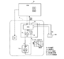
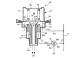
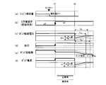
- FIG. 1 is a schematic configuration diagram of a fuel supply system according to a first embodiment of the present invention. It is a schematic block block diagram of the abnormality detection apparatus of the fuel supply system which concerns on 1st Embodiment of this invention. It is the sectional view showing the composition of the variable fuel pressure regulating valve in the fuel supply system concerning a 1st embodiment of the present invention. It is explanatory drawing of the fuel pressure switching abnormality detection operation
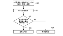
- FIG. 3 is a schematic flowchart showing a control procedure of a fuel pressure switching abnormality detection operation that is executed when the fuel injection amount becomes substantially constant in the abnormality detection device for a fuel supply system according to the first embodiment of the present invention. It is explanatory drawing of the fuel pressure switching abnormality detection operation performed just before an engine stop with the abnormality detection apparatus of the fuel supply system which concerns on 2nd Embodiment of this invention. It is the schematic flowchart which shows the one aspect
- (First embodiment) 1 to 5 show a first embodiment of an abnormality detection device for a fuel supply system according to the present invention.
- the present invention is applied to a fuel supply system for an internal combustion engine for a vehicle.
- this fuel supply system has a subtank in a fuel tank and a fuel pump or the like arranged in the subtank, and a fuel that introduces fuel into the subtank by the amount of fuel consumed successively by the engine.
- a known jet pump (not shown) is provided as a transfer means.
- the fuel supply system of this embodiment includes a fuel tank 2 that stores fuel consumed by an engine 1 (fuel consumption unit), for example, gasoline, and a sub tank 2a (hereinafter simply referred to as a fuel tank 2).
- a fuel pumping mechanism 10 that pumps and supplies fuel stored in a fuel tank 2 to a plurality of injectors 3 (a fuel injection section and a fuel consumption section of the internal combustion engine) of the engine 1, and the fuel pumping mechanism 10 to the injector 3
- the system pressure P1 is adjusted to a preset system pressure P1, and the system pressure P1 is set to any one of a plurality of set pressures, for example, a set pressure on the high pressure side and a set pressure on the low pressure side
- a pressure regulator 20 (variable fuel pressure regulating valve) that can be switched to any one of the pressures, and a current set pressure (optional) of the pressure regulator 20
- Setting pressure switching operation that can switch the pressure regulator 20 by the three-way solenoid valve 45 so that the setting pressure is switched to another setting pressure different
- the engine 1 is a multi-cylinder internal combustion engine mounted on an automobile, for example, a four-cycle gasoline engine.
- An injector 3 provided corresponding to a plurality of cylinders 1c of the engine 1 is, for example, an end portion on the injection hole side. 3a is exposed in the intake port 1a corresponding to each cylinder 1c. Further, the fuel from the fuel pumping mechanism 10 is distributed to each injector 3 via the delivery pipe 4.
- the fuel pumping mechanism 10 includes a fuel pump unit 11 that pumps up and discharges fuel in the fuel tank 2, a suction filter 12 that prevents foreign matter from being sucked on the suction port side of the fuel pump unit 11, and a fuel pump unit 11.
- the fuel filter 13 removes foreign matter in the discharged fuel on the discharge port side, and the check valve 14 (check valve) located upstream or downstream of the fuel filter 13.
- the fuel pump unit 11 includes, for example, a fuel pump 11p having an impeller for operating the pump, and a pump drive motor 11m that is a built-in DC motor that rotationally drives the fuel pump 11p.
- the fuel pump unit 11 is driven and stopped by controlling energization of the pump drive motor 11m by an ECU (electronic control unit) 51 described later.
- the fuel pump unit 11 can pump up fuel from the fuel tank 2, pressurize and discharge the fuel, and change the rotational speed [rpm] of the pump drive motor 11m according to the load torque with respect to the same supply voltage.
- the discharge amount and discharge pressure per unit time can be changed by changing the rotation speed of the pump drive motor 11m corresponding to the change of the supply voltage.
- the check valve 14 opens in the direction of fuel supply from the fuel pump unit 11 to the injector 3 side, while the check valve 14 is closed in the reverse flow direction of fuel from the injector 3 side to the fuel pump unit 11 side, and pressurized supply It is designed to prevent fuel backflow.
- the pressure regulator 20 includes a housing 21 having a fluid inlet 21a through which fuel is introduced and a fluid outlet 21b through which the fuel is discharged.
- the housing 21 is a pair of concave housings.
- the members 18 and 19 are formed by caulking and joining at their outer peripheral portions.
- the pressure regulating member 22 includes a partition wall portion 24 that forms a pressure regulating chamber 23 that communicates with the fluid introduction port 21a between the pressure regulating member 22 and the pressure regulating chamber 23 at an opening degree corresponding to the fuel pressure in the pressure regulating chamber 23.
- a partition wall portion 24 that forms a pressure regulating chamber 23 that communicates with the fluid introduction port 21a between the pressure regulating member 22 and the pressure regulating chamber 23 at an opening degree corresponding to the fuel pressure in the pressure regulating chamber 23.
- the partition wall portion 24 of the pressure regulating member 22 is also formed with a back pressure chamber 26 that applies back pressure to the pressure regulating chamber 23 side with the housing 21 on the other surface side.
- a compression coil spring 27 (elastic member) for urging the movable valve body 25 of the pressure regulating member 22 in the valve closing direction.
- at least one atmospheric pressure introduction hole 19 a is formed in the other housing member 19 that forms the back pressure chamber 26 together with the pressure regulating member 22.
- the partition wall portion 24 of the pressure adjusting member 22 is configured by a flexible diaphragm in which a rubber layer that is unlikely to deteriorate with respect to fuel is integrally bonded to the base material layer, for example.
- the movable valve body portion 25 is formed of, for example, a metal disc-like valve body plate supported at the center portion of the partition wall portion 24.
- first valve seat portion 31 and the second valve seat portion 32 are concentrically disposed inside the housing 21 so as to face the movable valve body portion 25 of the pressure regulating member 22 inside the pressure regulating chamber 23.
- the first valve seat portion 31 and the second valve seat portion 32 are constituted by an outer cylindrical member 35 and an inner cylindrical member 36 that have different diameters and are arranged coaxially.
- the first valve seat portion 31 forms a discharge passage 31h communicating with the fluid discharge port 21b on the inner peripheral side thereof
- the second valve seat portion 32 has the first valve seat portion 31 on the inner peripheral side thereof.
- An operating pressure introduction passage 32h is formed between the two.
- the housing 21, the pressure regulating member 22, and the outer cylindrical member 35 of the pressure regulator 20 introduce the fuel discharged from the fuel pump unit 11 from the radially outer fluid introduction port 21 a and receive the fuel pressure in the partition wall 24.
- An annular introduction side passage 37 is formed.
- the discharge passage 31h inside the first valve seat portion 31 communicates with the fluid discharge port 21b of the housing 21, and an operation pressure introduction passage 32h between the first valve seat portion 31 and the second valve seat portion 32. Is communicated with the operation pressure introducing hole 21 c of the housing 21.
- the fluid introduction port 21a of the housing 21 is connected to a fuel passage 15 which is a circuit portion downstream of the check valve 14 of the fuel pressure feeding mechanism 10 via a branch passage 15a, and an operation pressure introduction hole 21c of the housing 21 is connected. Is connected via a three-way solenoid valve 45 to a branch passage 16 which is a circuit portion upstream of the check valve 14 of the fuel pressure feeding mechanism 10.
- the three-way solenoid valve 45 constituting the set pressure switching operation mechanism 40 includes a first port 45 a connected to the branch passage 16 of the fuel pressure feeding mechanism 10 and a second port 45 b connected to the operation pressure introduction hole 21 c of the housing 21. And a third port 45 c corresponding to a drain port opened in the fuel tank 2.
- the three-way electromagnetic valve 45 supplies the first port 45a and the second port 45b so as to introduce the fuel pressurized by the fuel pressure feeding mechanism 10 into the operation pressure introduction passage 32h, and closes the third port 45c. Switchable to any one of the state and the drain state in which the second port 45b and the third port 45c are communicated to open the operating pressure introduction passage 32h into the fuel tank 2 and the first port 45a is closed. It is a valve.
- the three-way solenoid valve 45 is controlled to be switched between the supply state and the drain state by controlling the energization / excitation state of the electromagnetic operation unit 45d by the ECU 51.
- the branch passage 16, The ECU 51 and the three-way solenoid valve 45 constitute a set pressure switching operation mechanism 40 that executes control for switching the set pressure of the pressure regulator 20.
- the pressure receiving area of the pressure adjusting member 22 includes not only the annular pressure receiving surface 24a of the partition wall 24 but also the annular pressure receiving surface region (not shown) facing the second valve seat portion 32 and the operating pressure introduction passage 32h. It will be included. Accordingly, the area of the pressure receiving region of the pressure regulating member 22 varies depending on whether or not the operating pressure (pressurized fuel) is supplied to the operating pressure introduction passage 32h. When the area of the pressure receiving region of the pressure adjusting member 22 increases, the fuel pressure for opening the pressure adjusting member 22 against the biasing force of the compression coil spring 27 can be reduced. The fuel pressure regulation level decreases.
- the pressure regulator 20 thus has a pressure adjusting function for adjusting the fuel introduced into the annular introduction side passage 37 in the pressure adjusting chamber 23 to a preset set pressure, and is discharged from the fuel pump unit 11.
- the set pressure is set between the preset pressure on the high pressure side and the preset pressure on the low pressure side. It is possible to switch to any one set pressure.
- the set pressure on the high pressure side of the pressure regulator 20 is set to a fuel pressure (usually a gauge pressure of 324 kPa or more) at which fuel vapor hardly occurs even when the fuel temperature in the delivery pipe 4 becomes high immediately after the engine is stopped. It is a value.
- the set pressure on the low pressure side is, for example, 200 kPa as a gauge pressure, and is a fuel pressure set value at which fuel vapor hardly occurs when the fuel temperature in the delivery pipe 4 becomes relatively low during traveling.
- the ECU 51 includes an input interface in addition to a backup memory including a non-volatile memory such as a CPU (Central Processing Unit), a ROM (Read Only Memory), a RAM (Random Access Memory), and an EEPROM (Electrically, Erasable and Programmable Read Only Memory).
- the ECU 51 is configured to include an output interface circuit and the like.
- the ECU 51 receives an on / off signal of an ignition switch of the vehicle, and power is supplied from the battery 100 as shown in FIG. It has become.
- various sensor groups are connected to the input interface circuit of the ECU 51, and sensor information from these sensor groups is taken into the ECU 51 through an input interface circuit including an A / D converter and the like.
- the output interface circuit of the ECU 51 includes a relay switch for controlling actuators such as the injector 3, the fuel pump unit 11, and the three-way solenoid valve 45, a switching element for variably controlling the drive current of the fuel pump unit 11, and the like. Is connected.
- the ECU 51 can execute known electronic throttle control, fuel injection amount control, ignition timing control, fuel cut control, variable valve timing control, and the like by executing a control program stored in the ROM. For example, the ECU 51 calculates the basic injection amount required for each combustion based on the intake air amount detected by the air flow meter and the engine speed detected by the crank angle sensor, and further according to the operating state of the engine 1. The fuel injection amount subjected to various corrections, air-fuel ratio feedback correction, and the like is calculated, and the injector 3 corresponding to the fuel injection time corresponding to the fuel injection amount is driven to open. The fuel injection time here is set so as to maintain the stoichiometric air-fuel ratio according to the set value of the fuel pressure supplied to the injector 3.
- the ECU 51 generates a command value for the drive voltage of the pump drive motor 11m corresponding to the discharge amount so as to optimize the discharge amount of the fuel pump unit 11 according to the fuel injection amount required for the operation of the engine 1.
- it has a function of feedback-controlling the drive voltage of the pump drive motor 11m in cooperation with a fuel pump controller 52 described later.
- the ECU 51 repeatedly determines the load state during operation of the engine 1 based on sensor information from various sensor groups and setting values and map information stored in advance in the ROM, and 3 in the partial load operation region.
- the fuel from the fuel pump unit 11 is regulated to the set pressure on the low pressure side of the pressure regulator 20 as a non-excited state (hereinafter referred to as OFF state) in which the one-way solenoid valve 45 is returned to the supply state.
- OFF state non-excited state
- the ECU 51 sets the three-way electromagnetic valve 45 in the drain state (hereinafter referred to as an ON state) to pressure the fuel from the fuel pump unit 11.
- the regulator 20 is switched to a set pressure on the high pressure side.
- the setting values stored in the ROM and the backup memory of the ECU 51 include the setting value on the high pressure side and the setting value on the low pressure side of the fuel pressure, respectively.
- the map information stored in the ROM and the backup memory includes the driving value. A map and the like for load determination and fuel pressure switching control according to the determination result are included.
- the ECU 51 constantly diagnoses whether or not the exhaust emission can be suppressed within the legal regulation range during operation of the engine 1, and the exhaust emission within the legal regulation range. It has a function of turning on an MIL (abnormal warning lamp) (not shown) when an abnormality such as a failure that deviates from the inside occurs.
- MIL abnormal warning lamp
- a fuel pump controller 52 for controlling the operation of the fuel pump unit 11 is provided in the upper part of the fuel tank 2, and the fuel pump controller 52 includes a pump drive motor 11m.
- a voltage detection unit 53 that detects a terminal voltage and a current detection unit 54 that detects a current flowing through the pump drive motor 11m are mounted.
- the fuel pump controller 52 responds to the deviation between the pump control signal from the ECU 51 (command input for the above-described voltage feedback control) and the detection signal of the voltage detection unit 53 that detects the terminal voltage of the pump drive motor 11m.
- a diagnostic signal (Diag signal in FIG. 2) corresponding to the operating state of the pump drive motor 11m for controlling the voltage applied to the pump drive motor 11m of the unit 11 and for diagnosing abnormality of the fuel pumping mechanism 10 is sent to the ECU 51. Or can be supplied.
- the fuel pump controller 52 is supplied with power from the battery 100, and an ECU 51 is communicably connected thereto.
- the fuel pump controller 52 includes a relay switch circuit that switches on / off the energization of the pump drive motor 11m of the fuel pump unit 11 in accordance with a pump control signal from the ECU 51, a voltage applied to the pump drive motor 11m, or a pump A switching element or the like (not shown) for variably controlling the energy supplied to the drive motor 11m is incorporated.
- the switching element here is composed of, for example, a MOS-FET type transistor that variably controls the energy supplied to the coil of the pump drive motor 11m of the fuel pump unit 11 in accordance with a PWM (Pulse Width Modulation) input signal.
- the fuel pump controller 52 has a rotation speed detection unit that detects the rotation speed [rpm] of the pump drive motor 11m under a substantially constant drive voltage of the pump drive motor 11m, instead of the current detection unit 54. Also good.
- the ECU 51 changes the state of energization of the pump drive motor 11m after the set pressure of the pressure regulator 20 is switched, as a fuel pump controller 52. It is determined whether or not an abnormality has occurred in the switching of the set pressure of the pressure regulator 20 based on the state change detection unit 51a (state change detection means) that is detected by the diagnostic signal from and the detection information of the state change detection unit 51a An abnormality determination unit 51b (abnormality determination means).
- the state change detection unit 51a of the ECU 51 has a substantially constant fuel injection amount [g / sec] of the injector 3 of the engine 1 which is a fuel consumption unit, and the fuel supply amount per unit time of the fuel pump unit 11 and the pump drive.
- the set pressure of the pressure regulator 20 is changed from the set pressure on the low pressure side, which is the first set pressure among the set pressures, to the set pressure.
- the three-way solenoid valve 45 of the set pressure switching operation mechanism 40 is operated so as to switch to the set pressure on the high pressure side, which is the second set pressure, and the change in the energization current of the pump drive motor 11m due to the switching of the set pressure is fueled. It is detected by a diagnostic signal from the pump controller 52.
- the abnormality determination unit 51b of the ECU 51 determines the excitation state of the three-way solenoid valve 45 under the operation pressure introduction passage 32h under a specific condition in which the fuel injection amount from the injector 3 (fuel supply amount to the injector 3) is substantially constant.
- a fuel pressure switching operation for switching from an OFF state in which the operating pressure is supplied to the ON state to release the operating pressure to switch the set pressure (fuel pressure) of the pressure regulator 20 from the set pressure on the low pressure side to the set pressure on the high pressure side, at least A voltage holding operation that keeps the pump drive voltage applied to the pump drive motor 11m of the fuel pump unit 11 constant within a fixed time before and after the fuel pressure switching operation, and a diagnostic signal from the state change detection unit 51a.
- the abnormality determination process here is a change in the state of energization of the pump drive motor 11m according to the switching of the set pressure of the pressure regulator 20, for example, a clear change in the energization current of the pump drive motor 11m after the set pressure is switched ( If there is a significant change exceeding the fluctuation error range), it is determined that the fuel pressure has been switched normally, and if the energization current of the pump drive motor 11m does not change clearly after the set pressure has been switched. It is determined that some abnormality that hinders fuel pressure switching has occurred.
- this abnormality determination process not a clear change in the energization current of the pump drive motor 11m after switching the set pressure of the pressure regulator 20, but a clear change in the rotation speed of the pump drive motor 11m corresponding thereto has occurred. For example, it can be determined that the fuel pressure has been switched normally, and if such a clear change in the rotational speed has not occurred, it can be determined that some abnormality that prevents the fuel pressure switching has occurred.
- the specific condition in which the fuel supply amount per unit time to the injector 3 is substantially constant is, for example, a state in which the fuel injection amount in the injector 3 is substantially constant below a certain amount.
- an idle operation state after completion of warm-up of the engine 1 (ii) fuel in which fuel injection from the injectors 3 corresponding to at least some cylinders is temporarily stopped during operation of the engine 1 during deceleration of the vehicle A cut operation state or a cylinder deactivation operation state, or (iii) a low-speed rotation state immediately before the engine 1 is stopped and a fuel pressure switchable state in which the rotation of the fuel pump unit 11 is continued.
- the energization of the pump drive motor 11m and the three-way electromagnetic valve 45 of the fuel pump unit 11 is stopped while the engine 1 is stopped.
- pressurized fuel is not supplied to the operation pressure introduction passage 32h of the pressure regulator 20, but the ECU 51 temporarily turns on the pressure of the three-way solenoid valve 45 immediately before the engine 1 enters the current stop state. Since the regulator 20 is stopped after being switched to the set pressure on the high pressure side, the fuel pressure in the fuel pressure holding section from the check valve 14 to the injector 3 is maintained at a relatively high fuel pressure that is unlikely to generate fuel vapor.
- the fuel pump unit 11 When the engine 1 is started, the fuel pump unit 11 is started by the ECU 51. At this time, the three-way solenoid valve 45 is turned on, and the pressure regulator 20 is switched to the set pressure on the high pressure side. Therefore, when the discharge pressure of the fuel pump unit 11 rises and the fuel from the fuel pump unit 11 is introduced into the annular introduction side passage 37 in the pressure regulating chamber 23, the pressure of the fuel is quickly set to the high pressure side.
- the pressure reaches, for example, 400 [kPa], and the high fuel pressure system pressure P 1 is supplied to the delivery pipe 4 through the fuel passage 15. Therefore, when fuel pumping by the fuel pumping mechanism 10 is resumed, fuel supply with sufficient fuel pressure can be started immediately.
- a set pressure on the low pressure side is required in terms of fuel economy and the reliability of the fuel pump unit 11.
- the three-way solenoid valve 45 is in an OFF state in which the operation pressure is supplied to the operation pressure introduction passage 32h, and the fuel pump is in a state where the set pressure of the pressure regulator 20 is switched to the set pressure on the low pressure side. The operation of the unit 11 is continued.
- the three-way solenoid valve 45 is turned on, and the fuel from the fuel pump unit 11 is regulated to the set pressure on the high pressure side in the introduction side passage 37 in the pressure regulating chamber 23.
- the ECU 51 determines whether or not the exhaust emission of the engine 1 can be suppressed within the legally regulated range by a procedure as shown in FIG. Is diagnosed at least once during the operation period of the engine 1.
- the state change detection unit 51a of the ECU 51 first changes the set pressure of the pressure regulator 20 from the set pressure on the low pressure side to the set pressure on the high pressure side.
- the three-way solenoid valve 45 is turned on so as to switch to (step S11), and the energization current of the pump drive motor 11m after the switching of the set pressure is detected based on the diagnostic signal from the fuel pump controller 52, respectively.
- the abnormality determination unit 51b adds the fuel pressure to the energization current of the pump drive motor 11m after the set pressure is switched based on the driving connection of the pump drive motor 11m input as a diagnostic signal from the state change detection unit 51a. Depending on whether or not there is a clear change corresponding to the switching, an abnormality determination process is performed to determine whether the fuel pressure switching by switching the set pressure of the pressure regulator 20 has been performed normally or whether an abnormality has occurred in the fuel pressure switching ( Step S12).
- the pressure regulator 20 becomes high pressure as the three-way solenoid valve 45 is switched to the ON state, as shown in FIGS. 4 (a) to 4 (f).
- the fuel pressure in the fuel pressure holding section from the check valve 14 to the injector 3 increases, while the rotational load (load torque) of the pump drive motor 11m of the fuel pump unit 11 after the set pressure is switched.
- load torque load torque
- the pump speed decreases, the back electromotive force of the pump drive motor 11m proportional to it decreases, and the current flowing through the pump drive motor 11m increases.
- step S12 when there is a clear change in the energization current of the pump drive motor 11m according to the switching of the set pressure of the pressure regulator 20 (YES in step S12), the switching of the set pressure of the pressure regulator 20 is normally performed.
- step S13 when it is determined that the flow has been completed (step S13), and no clear change has occurred in the energization current of the pump drive motor 11m according to the switching of the set pressure of the pressure regulator 20 (NO in step S12), It is determined that there is an abnormality occurrence state in which switching of the set pressure of the pressure regulator 20 cannot be completed normally due to the abnormality (step S14).
- the substantially constant applied voltage to the pump drive motor 11m here is Ev [V]
- the counter electromotive force coefficient in the pump drive motor 11m is Ke
- the rotation speed of the pump drive motor 11m is N [rpm]
- the pump drive motor 11m Is I and the internal resistance of the pump drive motor 11m is R
- Em Ke ⁇ N
- the current I and the rotational speed N have a 1: 1 proportional relationship in which the current I decreases as the rotational speed N increases.
- the rotational speeds of the fuel pump unit 11 and the pump drive motor 11m change, and the pump drive.
- the current I flowing through the motor 11m changes.
- the pump drive voltage Ev can be made substantially constant, and the current I flowing through the pump drive motor 11m can be clearly changed according to the change in fuel pressure.
- the clear change of the current I can be detected with low noise. Therefore, it is possible to reliably detect whether the fuel pressure switching operation is normal or abnormal based on whether there is a change in the current flowing through the pump drive motor 11m without using the fuel pressure sensor or the detection information of the air / fuel sensor.
- the state change detection unit 51a of the ECU 51 when the state change detection unit 51a of the ECU 51 is in a fuel cut state during which the engine 1 is in operation and fuel injection from the injector 3 is temporarily stopped, the energization current of the pump drive motor 11m or a state change corresponding thereto is detected. Since it can be detected, the fuel injection amount becomes zero or substantially constant, the pump drive voltage can be made substantially constant, and in this state, the current flowing through the pump drive motor 11m can be clearly changed according to the change in fuel pressure. Therefore, a change in the energization current of the pump drive motor 11m can be detected with low noise, and whether the fuel pressure switching operation is normal or abnormal can be reliably detected.
- the set pressure of the pressure regulator 20 is switched from the set pressure on the low pressure side to the set pressure on the high pressure side prior to the stop.
- the generation of fuel vapor at the start is effectively suppressed, and the startability of the engine 1 is improved.
- the change in the state of energization of the pump drive motor 11m is detected by the state change detection unit 51a of the ECU 51 using the change of the set pressure of the pressure regulator 20 when the engine 1 is stopped, the fuel pressure changeover operation is performed. Whether it is normal or abnormal can be reliably detected.
- the abnormality can be reliably detected by the time, and the problem that the abnormality cannot be detected until after the next start of the engine 1 does not occur.
- the set pressure of the pressure regulator 20 is increased from the set pressure on the low pressure side.
- the state change detector 51a detects a change in the state of energization of the pump drive motor 11m after the change, and based on the detected information, has an abnormality occurred in the change of the fuel pressure by the pressure regulator 20? Since abnormality determination of whether or not is performed, it is possible to reliably detect abnormality of the fuel pressure switching operation without using an expensive fuel pressure sensor or using detection information of the air fuel sensor, and fuel pressure switching is possible.
- the difference in the low-cost fuel supply system that can reliably detect the abnormality of the fuel pressure switching operation in the fuel supply system It is possible to provide a detection apparatus.
- FIGS. 6 to 9 are views showing a second embodiment of the abnormality detection device for a fuel supply system according to the present invention.
- the present embodiment has an overall configuration substantially similar to that of the first embodiment described above, and only the abnormality detection method in the abnormality detection apparatus is different from the first embodiment. Therefore, for the same configuration as in the first embodiment, the reference numerals of the corresponding components in the first embodiment shown in FIGS. 1 to 5 are used, and only differences from the first embodiment will be described below.
- the ECU 51 is in a low-speed rotation state immediately before the operation of the engine 1 is stopped and the fuel pump unit 11 continues to rotate.
- the three-way solenoid valve 45 is turned on so that the pressure is switched from the set pressure on the low pressure side to the set pressure on the high pressure side.
- the state change detection unit 51a of the ECU 51 starts from a time point when the pump drive voltage decreases (a time point when a signal instructing the pump drive motor 11m to stop) is generated.
- a change in the state of energization of the pump drive motor 11m within a required stop time until the pump drive motor 11m actually stops is detected based on a diagnostic signal from the fuel pump controller 52.
- the pressure regulator 20 is set to the high pressure side when the three-way solenoid valve 45 is switched to the ON state, as shown in FIGS. 6 (a) to 6 (f).
- the fuel pressure in the fuel pressure holding section from the check valve 14 to the injector 3 increases, while the rotational load (load torque) of the pump drive motor 11m of the fuel pump unit 11 increases by switching the set pressure.
- the pump speed decreases, the back electromotive force of the pump drive motor 11m proportional to the pump speed decreases, and the current flowing through the pump drive motor 11m temporarily increases.
- the pump drive voltage is switched to zero after the current flowing through the pump drive motor 11m once increases due to the set pressure switching of the pressure regulator 20 (see FIG. 6C).
- the state change detector 51a of the ECU 51 causes the pressure regulator 20 to move as shown in FIG. 6B and FIG.
- the three-way solenoid valve 45 is switched to the ON state so as to switch the set pressure from the set pressure on the low pressure side to the set pressure on the high pressure side (timing indicated by t1 in FIG. 6B; step S21).
- the ECU 51 reduces the pump drive voltage to zero so that the pump drive motor 11m is stopped to stop the engine 1, thereby stopping the pump drive motor 11m. Instructed (timing indicated by t2 in FIG. 6C; step S22).
- a substantially constant applied voltage to the pump drive motor 11m is Ev [V]
- the counter electromotive force coefficient in the pump drive motor 11m is Ke
- the rotation speed of the pump drive motor 11m is N [ rpm]
- the current flowing through the pump drive motor 11m is I [A]
- the internal resistance of the pump drive motor 11m is R [ ⁇ ]
- the applied voltage Ev of the pump drive motor 11m is 0 during the operation of the fuel pump unit 11.
- Steps S23, S24 refer to the solid line in FIG. 6C.
- the voltage change amount immediately after the stop instruction of the pump drive motor 11m is a large change amount Em ′ exceeding the specified value va, the normal state is obtained. It can be determined that an abnormal state has occurred in which some abnormality that prevents the fuel pressure from being switched (steps S23 and S25; see the broken line in FIG. 6C).
- Step S21 and S22 when a current change amount due to the counter electromotive force immediately after the stop instruction of the pump drive motor 11m occurs, the pump drive motor 11m from the time when the power supply to the pump drive motor 11m is stopped. If the required stop time until the point at which the actual rotation stops becomes a required stop time Tm within a specified time Ta (for example, about 0.1 second), it can be determined that the fuel has been switched normally. (Steps S33, S34; see solid line in FIG. 6C) On the other hand, the required stop time from the time when power supply to the pump drive motor 11m is stopped to the time when the pump drive motor 11m stops its actual rotation is a specified time Ta. If the required stop time Tm ′ exceeds, it can be determined that there is an abnormal state in which some abnormality that hinders normal fuel pressure switching occurs. See the broken line in FIG. 6 (c));-up S33, S35.
- step S21 and S22 if the amount of current change due to the back electromotive force immediately after the stop instruction of the pump drive motor 11m becomes the amount of change im below the specified value ia, normal fuel pressure switching is performed. It can be determined that the normal state has been made (steps S43 and S44; see the solid line in FIG. 6 (f)). On the other hand, the amount of current change immediately after the stop instruction of the pump drive motor 11m exceeds the specified value ia If it is im ′, it can be determined that there is an abnormal state in which some abnormality that prevents normal fuel pressure switching has occurred (steps S43 and S45; see the broken line in FIG. 6F).
- the state change detector 51a of the ECU 51 detects the amount of change in voltage, current, or required stop time caused by the counter electromotive force in the pump drive motor 11m when the pump drive motor 11m is stopped. Based on the detected change amount, the abnormality determination unit 51b of the ECU 51 determines whether an abnormality has occurred in the switching of the set pressure of the pressure regulator 20.
- the current detector 54 when detecting the voltage changes Em and Em ′ due to the back electromotive force immediately after the stop instruction of the pump drive motor 11m, the current detector 54 can be omitted, and the manufacturing cost is reduced. it can.
- the current change amount when detecting the current change amounts im and im ′ due to the counter electromotive force immediately after the stop instruction of the pump drive motor 11m, the current change amount can be detected with high accuracy, so that the abnormality detection accuracy can be improved.
- the ON and OFF times are not the absolute values of voltage and current. Therefore, it is possible to accurately detect the current change due to the back electromotive force and to ensure the required abnormality detection accuracy.
- the change in energization current can be detected not only as a change in voltage across the electric resistance connected in series with the pump drive motor, but also as a change in pump speed under a constant pump voltage, for example. Of course, it is also possible.
- the state change detection unit 51a of the ECU 51 switches the fuel pressure according to the current change of the pump drive motor 11m when the fuel pressure is switched under a specific condition in which the fuel supply amount to the injector 3 is constant.
- the two types of inspections may be used together, or a plurality of types of voltage change amounts Em and Em ′, current change amounts im and im ′, and required stop times Tm and Tm ′ may be combined in the second embodiment. Needless to say, abnormality detection can be performed using a plurality of change amounts.
- a change in the energization state of the pump drive motor 11m when the set pressure on the low pressure side is switched to the set pressure on the high pressure side is detected, but the set pressure on the high pressure side is changed to the set pressure on the low pressure side. It is also possible to detect a change in the energization state of the pump drive motor 11m at the time of switching.
- the present invention is applicable to a fuel supply system of a variable fuel pressure adjustment system in which the set pressure is not controlled in two stages but controlled in multiple stages.
- the pressure regulator 20 is excited in the single case having the operation pressure supply / discharge passage in addition to the pressure adjustment passage and the discharge passage.
- the present invention is not limited to the system, and a plurality of fluid circuit elements may be used in combination as long as it can be switched to an arbitrary set pressure among a plurality of different set pressures.
- the amount of fuel supplied to the injector 3 in the operating state of the engine 1 is as follows.
- the drive voltage of the pump drive motor 11m does not have to be strictly constant, and can vary within a range where an abnormality can be detected with a somewhat good S / N ratio. That is, the fact that the fuel supply amount is substantially constant means that the fuel supply amount can vary within a range in which the required detection accuracy can be ensured (within a predetermined error range). Is within a range narrower than the fluctuation range of the exhaust fuel flow rate from the pressure regulator 20 within the set pressure range.
- the abnormality detection device for the fuel supply system changes the set pressure of the variable fuel pressure adjusting valve from the first set pressure to the second set value when the fuel supply amount to the fuel consumption unit becomes substantially constant.
- the change in the state of energization of the pump drive motor after the switching is detected by the state change detection means, and whether or not an abnormality has occurred in the fuel pressure switching by the variable fuel pressure adjustment valve based on the detected information Therefore, it is possible to reliably detect an abnormality in the fuel pressure switching operation without using an expensive fuel pressure sensor or using detection information from the air / fuel sensor.
- an abnormality detection device for a low-cost fuel supply system that can reliably detect an abnormality in the fuel pressure switching operation in the supply system.
Landscapes
- Engineering & Computer Science (AREA)
- Chemical & Material Sciences (AREA)
- Combustion & Propulsion (AREA)
- Mechanical Engineering (AREA)
- General Engineering & Computer Science (AREA)
- Electrical Control Of Air Or Fuel Supplied To Internal-Combustion Engine (AREA)
- Combined Controls Of Internal Combustion Engines (AREA)
Abstract
Description
図1~図5は、本発明に係る燃料供給システムの異常検出装置の第1実施形態を示している。なお、本実施形態は、本発明を車両用の内燃機関の燃料供給システムに適用したものである。また、この燃料供給システムは、燃料タンク内にサブタンクを設け、そのサブタンク内に燃料ポンプ等を配したものであり、エンジンで遂次消費される燃料消費量分だけサブタンク内に燃料を導入する燃料移送手段として図示しない公知のジェットポンプを有している。
図6~図9は、本発明に係る燃料供給システムの異常検出装置の第2実施形態を示す図である。なお、本実施形態は、上述の第1実施形態と略同様の全体構成を有しており、その異常検出装置における異常検出方法のみが第1実施形態と相違するものである。したがって、第1実施形態と同様の構成については図1~図5に示した第1実施形態の対応する構成要素の参照符号を用い、第1実施形態との相違点についてのみ以下に説明する。
2 燃料タンク
2a サブタンク
3 インジェクタ(燃料消費部)
4 デリバリーパイプ
10 燃料圧送機構
11 燃料ポンプユニット
11m ポンプ駆動モータ
11p 燃料ポンプ
15 燃料通路
16 分岐通路
20 プレッシャレギュレータ(可変燃圧調整弁)
21 ハウジング
22 調圧部材
26 背圧室
31 第1弁座部
32 第2弁座部
40 設定圧切換操作機構
45 3方電磁弁
45a 第1ポート
45b 第2ポート
45c 第3ポート
45d 電磁操作部
51 ECU(電子制御ユニット)
51a 状態変化検出部(状態変化検出手段)
51b 異常判定部(異常判定手段)
52 燃料ポンプコントローラ
53 電圧検出部
54 電流検出部
P1 システム圧
Pw 操作圧
Claims (7)
- 燃料消費部に燃料を供給するようポンプ駆動モータによって駆動される燃料ポンプと、
前記燃料ポンプから前記燃料消費部に供給される燃料を導入し、該燃料の圧力を異なる複数の設定圧のうち任意の1つの設定圧に調整可能な可変燃圧調整弁と、
前記任意の1つの設定圧を前記複数の設定圧のうち他の1つの設定圧に切り換えるよう前記可変燃圧調整弁を操作する操作手段と、を備えた燃料供給システムにあって、
前記燃料消費部への単位時間当りの燃料供給量が略一定となるときに前記可変燃圧調整弁の設定圧を前記複数の設定圧のうち第1の設定圧から第2の設定圧に切り換えるよう前記操作手段を作動させ、該設定圧の切換え後の前記ポンプ駆動モータの通電にかかる状態の変化を検出する状態変化検出手段と、
前記状態変化検出手段の検出情報に基づいて前記可変燃圧調整弁の前記設定圧の切換えに異常が生じたか否かを判定する異常判定手段と、を備えたことを特徴とする燃料供給システムの異常検出装置。 - 前記状態変化検出手段が、前記設定圧の切換え後における前記ポンプ駆動モータの通電電流の変化を検出することを特徴とする請求項1に記載の燃料供給システムの異常検出装置。
- 前記燃料消費部が、内燃機関の燃料噴射部であり、
前記状態変化検出手段は、前記内燃機関の運転中に燃料噴射部からの燃料噴射量が略一定となるアイドル運転時に前記ポンプ駆動モータの通電にかかる状態の変化を検出することを特徴とする請求項1または請求項2に記載の燃料供給システムの異常検出装置。 - 前記燃料消費部が、内燃機関の燃料噴射部であり、
前記状態変化検出手段は、前記内燃機関の運転中に燃料噴射部からの燃料噴射が一時的に停止される燃料カット時に前記ポンプ駆動モータの通電にかかる状態の変化を検出することを特徴とする請求項1ないし請求項3のうちいずれか1の請求項に記載の燃料供給システムの異常検出装置。 - 前記燃料消費部が、内燃機関の燃料噴射部であり、
前記操作手段が、前記内燃機関が停止されるときに前記可変燃圧調整弁の設定圧を前記複数の設定圧のうち低圧側の設定圧から高圧側の設定圧に切り換えるとともに、
前記状態変化検出手段が、前記内燃機関が停止されるときの前記ポンプ駆動モータの通電にかかる状態の変化を検出することを特徴とする請求項1ないし請求項4のうちいずれか1の請求項に記載の燃料供給システムの異常検出装置。 - 前記状態変化検出手段は、前記内燃機関の停止のために前記ポンプ駆動モータが停止されるとき、該ポンプ駆動モータの停止を指示する信号の発生時点から前記ポンプ駆動モータが停止する時点までの停止時間内における前記ポンプ駆動モータの通電にかかる状態の変化を検出することを特徴とする請求項1ないし請求項5のうちいずれか1の請求項に記載の燃料供給システムの異常検出装置。
- 前記状態変化検出手段は、前記ポンプ駆動モータを停止させるときの所要停止時間を前記ポンプ駆動モータの電流または電圧の変化に基づいて検出し、
前記異常判定手段は、検出された前記所要停止時間に基づいて前記可変燃圧調整弁の前記設定圧の切換えに異常が生じたか否かを判定することを特徴とする請求項7に記載の燃料供給システムの異常検出装置。
Priority Applications (3)
| Application Number | Priority Date | Filing Date | Title |
|---|---|---|---|
| JP2013504396A JP5655930B2 (ja) | 2011-03-14 | 2011-03-14 | 燃料供給システムの異常検出装置 |
| US14/004,587 US20130340721A1 (en) | 2011-03-14 | 2011-03-14 | Abnormality detection apparatus for a fuel supply system |
| PCT/JP2011/001465 WO2012123985A1 (ja) | 2011-03-14 | 2011-03-14 | 燃料供給システムの異常検出装置 |
Applications Claiming Priority (1)
| Application Number | Priority Date | Filing Date | Title |
|---|---|---|---|
| PCT/JP2011/001465 WO2012123985A1 (ja) | 2011-03-14 | 2011-03-14 | 燃料供給システムの異常検出装置 |
Publications (1)
| Publication Number | Publication Date |
|---|---|
| WO2012123985A1 true WO2012123985A1 (ja) | 2012-09-20 |
Family
ID=46830125
Family Applications (1)
| Application Number | Title | Priority Date | Filing Date |
|---|---|---|---|
| PCT/JP2011/001465 Ceased WO2012123985A1 (ja) | 2011-03-14 | 2011-03-14 | 燃料供給システムの異常検出装置 |
Country Status (3)
| Country | Link |
|---|---|
| US (1) | US20130340721A1 (ja) |
| JP (1) | JP5655930B2 (ja) |
| WO (1) | WO2012123985A1 (ja) |
Cited By (2)
| Publication number | Priority date | Publication date | Assignee | Title |
|---|---|---|---|---|
| JP2014202132A (ja) * | 2013-04-04 | 2014-10-27 | 株式会社デンソー | 燃料ポンプの制御装置 |
| JP2021063451A (ja) * | 2019-10-11 | 2021-04-22 | トヨタ自動車株式会社 | エンジン制御装置 |
Families Citing this family (9)
| Publication number | Priority date | Publication date | Assignee | Title |
|---|---|---|---|---|
| JP2014084860A (ja) * | 2012-10-25 | 2014-05-12 | Hyundai Motor Company Co Ltd | 車両の燃料ポンプ制御方法 |
| JP6124728B2 (ja) * | 2013-08-07 | 2017-05-10 | 本田技研工業株式会社 | 燃料ポンプの制御装置 |
| DE102014222404A1 (de) * | 2014-11-03 | 2016-05-04 | Continental Automotive Gmbh | Verfahren zur Überprüfung eines mit einem Druck korrelierenden Parameters in einem druckabhängigen Fluidfördersystem, Steuergerät und Fluidfördersystem |
| DE102014226972A1 (de) * | 2014-12-23 | 2016-06-23 | Continental Automotive Gmbh | Fördervorrichtung zum Befördern eines Mediums und zum Begrenzen eines Systemdrucks |
| US10094308B2 (en) * | 2015-09-25 | 2018-10-09 | Cummins, Inc. | System, method, and apparatus for improving the performance of an operator of a vehicle |
| US10605151B2 (en) * | 2016-06-09 | 2020-03-31 | GM Global Technology Operations LLC | Electric pump operating strategy |
| CN108146343B (zh) * | 2016-12-02 | 2021-01-05 | 财团法人资讯工业策进会 | 预警系统及预警方法 |
| CN111005828B (zh) * | 2019-12-27 | 2021-03-16 | 潍柴动力股份有限公司 | 一种燃气消耗检测方法及装置 |
| JP7718348B2 (ja) * | 2022-08-03 | 2025-08-05 | 株式会社デンソー | モータ制御装置 |
Citations (4)
| Publication number | Priority date | Publication date | Assignee | Title |
|---|---|---|---|---|
| JPH05321737A (ja) * | 1992-05-19 | 1993-12-07 | Honda Motor Co Ltd | 燃圧レギュレータコントロールシステムの異常検知装置 |
| JP2004162529A (ja) * | 2002-09-19 | 2004-06-10 | Keihin Corp | 液体ポンプシステム |
| JP2007315378A (ja) * | 2006-04-26 | 2007-12-06 | Nikki Co Ltd | エンジンの燃料供給装置 |
| JP2010255471A (ja) * | 2009-04-22 | 2010-11-11 | Toyota Motor Corp | 内燃機関の故障診断装置 |
Family Cites Families (6)
| Publication number | Priority date | Publication date | Assignee | Title |
|---|---|---|---|---|
| US5235954A (en) * | 1992-07-09 | 1993-08-17 | Anatoly Sverdlin | Integrated automated fuel system for internal combustion engines |
| JPH08338335A (ja) * | 1995-06-09 | 1996-12-24 | Nippondenso Co Ltd | 内燃機関の燃料供給装置 |
| JP3554167B2 (ja) * | 1997-12-02 | 2004-08-18 | 株式会社日立製作所 | 筒内噴射エンジンの制御装置 |
| JP2002317668A (ja) * | 2001-02-14 | 2002-10-31 | Sanshin Ind Co Ltd | 水ジェット推進艇のエンジン制御装置 |
| US6915787B2 (en) * | 2002-05-29 | 2005-07-12 | Mitsubishi Denki Kabushiki Kaisha | Fuel supply apparatus and fuel pressure regulator |
| CN101971003B (zh) * | 2009-05-18 | 2012-09-19 | 丰田自动车株式会社 | 燃料粘度检测装置 |
-
2011
- 2011-03-14 JP JP2013504396A patent/JP5655930B2/ja not_active Expired - Fee Related
- 2011-03-14 WO PCT/JP2011/001465 patent/WO2012123985A1/ja not_active Ceased
- 2011-03-14 US US14/004,587 patent/US20130340721A1/en not_active Abandoned
Patent Citations (4)
| Publication number | Priority date | Publication date | Assignee | Title |
|---|---|---|---|---|
| JPH05321737A (ja) * | 1992-05-19 | 1993-12-07 | Honda Motor Co Ltd | 燃圧レギュレータコントロールシステムの異常検知装置 |
| JP2004162529A (ja) * | 2002-09-19 | 2004-06-10 | Keihin Corp | 液体ポンプシステム |
| JP2007315378A (ja) * | 2006-04-26 | 2007-12-06 | Nikki Co Ltd | エンジンの燃料供給装置 |
| JP2010255471A (ja) * | 2009-04-22 | 2010-11-11 | Toyota Motor Corp | 内燃機関の故障診断装置 |
Cited By (3)
| Publication number | Priority date | Publication date | Assignee | Title |
|---|---|---|---|---|
| JP2014202132A (ja) * | 2013-04-04 | 2014-10-27 | 株式会社デンソー | 燃料ポンプの制御装置 |
| JP2021063451A (ja) * | 2019-10-11 | 2021-04-22 | トヨタ自動車株式会社 | エンジン制御装置 |
| JP7207253B2 (ja) | 2019-10-11 | 2023-01-18 | トヨタ自動車株式会社 | エンジン制御装置 |
Also Published As
| Publication number | Publication date |
|---|---|
| US20130340721A1 (en) | 2013-12-26 |
| JP5655930B2 (ja) | 2015-01-21 |
| JPWO2012123985A1 (ja) | 2014-07-17 |
Similar Documents
| Publication | Publication Date | Title |
|---|---|---|
| JP5655930B2 (ja) | 燃料供給システムの異常検出装置 | |
| JP4657140B2 (ja) | エンジンの燃料供給装置 | |
| JP3680515B2 (ja) | 内燃機関の燃料系診断装置 | |
| JP4781899B2 (ja) | エンジンの燃料供給装置 | |
| JP5212546B2 (ja) | 燃料供給装置 | |
| JP5059894B2 (ja) | 燃料ポンプ制御装置 | |
| WO2011132677A1 (ja) | エアフローメータの故障診断装置 | |
| US7493804B2 (en) | Method and device for monitoring a fuel supplying device of an internal combustion engine | |
| JP2000328916A (ja) | エンジンの潤滑制御装置 | |
| JP4529871B2 (ja) | 内燃機関装置の異常検出装置 | |
| JP4372510B2 (ja) | 車両の制御装置 | |
| JPH11190230A (ja) | エンジンの絞り弁制御装置および制御方法 | |
| JP2013064378A (ja) | 内燃機関の燃料供給制御装置 | |
| JP2002349357A (ja) | 排出ガス環流システムの異常診断装置 | |
| JP4657170B2 (ja) | エンジンの燃料供給装置 | |
| JP4254619B2 (ja) | 故障診断装置 | |
| JP5295909B2 (ja) | 内燃機関の運転制御方法 | |
| JP2004150302A (ja) | エンジンの異常判定装置 | |
| JP4263128B2 (ja) | 流量制御バルブ用ステップモータの駆動制御装置及び駆動制御方法 | |
| JP2010071133A (ja) | エンジンの燃料供給装置 | |
| JP2012189083A (ja) | エンジンの燃料供給装置 | |
| JP4098802B2 (ja) | 内燃機関の制御装置 | |
| US7313912B2 (en) | Secondary air supply system for internal combustion engine | |
| JP3890830B2 (ja) | O2センサ診断装置 | |
| JP3360463B2 (ja) | 燃料蒸散防止装置の診断装置 |
Legal Events
| Date | Code | Title | Description |
|---|---|---|---|
| 121 | Ep: the epo has been informed by wipo that ep was designated in this application |
Ref document number: 11861069 Country of ref document: EP Kind code of ref document: A1 |
|
| ENP | Entry into the national phase |
Ref document number: 2013504396 Country of ref document: JP Kind code of ref document: A |
|
| WWE | Wipo information: entry into national phase |
Ref document number: 14004587 Country of ref document: US |
|
| NENP | Non-entry into the national phase |
Ref country code: DE |
|
| 122 | Ep: pct application non-entry in european phase |
Ref document number: 11861069 Country of ref document: EP Kind code of ref document: A1 |