WO2012121116A1 - ディスプレイ装置用結晶化ガラス - Google Patents
ディスプレイ装置用結晶化ガラス Download PDFInfo
- Publication number
- WO2012121116A1 WO2012121116A1 PCT/JP2012/055279 JP2012055279W WO2012121116A1 WO 2012121116 A1 WO2012121116 A1 WO 2012121116A1 JP 2012055279 W JP2012055279 W JP 2012055279W WO 2012121116 A1 WO2012121116 A1 WO 2012121116A1
- Authority
- WO
- WIPO (PCT)
- Prior art keywords
- glass
- zro
- display device
- crystallized
- crystallized glass
- Prior art date
- Legal status (The legal status is an assumption and is not a legal conclusion. Google has not performed a legal analysis and makes no representation as to the accuracy of the status listed.)
- Ceased
Links
Images

Classifications
-
- C—CHEMISTRY; METALLURGY
- C03—GLASS; MINERAL OR SLAG WOOL
- C03C—CHEMICAL COMPOSITION OF GLASSES, GLAZES OR VITREOUS ENAMELS; SURFACE TREATMENT OF GLASS; SURFACE TREATMENT OF FIBRES OR FILAMENTS MADE FROM GLASS, MINERALS OR SLAGS; JOINING GLASS TO GLASS OR OTHER MATERIALS
- C03C10/00—Devitrified glass ceramics, i.e. glass ceramics having a crystalline phase dispersed in a glassy phase and constituting at least 50% by weight of the total composition
- C03C10/0018—Devitrified glass ceramics, i.e. glass ceramics having a crystalline phase dispersed in a glassy phase and constituting at least 50% by weight of the total composition containing SiO2, Al2O3 and monovalent metal oxide as main constituents
- C03C10/0027—Devitrified glass ceramics, i.e. glass ceramics having a crystalline phase dispersed in a glassy phase and constituting at least 50% by weight of the total composition containing SiO2, Al2O3 and monovalent metal oxide as main constituents containing SiO2, Al2O3, Li2O as main constituents
Definitions
- the present invention relates to a transparent high-strength crystallized glass suitable for a display device, typically a mobile phone, a personal digital assistant (PDA), a tablet personal computer with a touch sensor function, a cover glass of a small display device such as a touch panel.
- a display device typically a mobile phone, a personal digital assistant (PDA), a tablet personal computer with a touch sensor function, a cover glass of a small display device such as a touch panel.
- cover glasses for protecting a display and enhancing aesthetics are often used for mobile devices (portable information devices) such as mobile phones and PDAs.
- mobile devices portable information devices
- the cover glass used for display protection is also required to be thin.
- the thickness of the cover glass is reduced, the strength decreases, and the cover glass itself may be broken due to falling in use or while carrying it, which plays the original role of protecting the display device. There was a problem that it was impossible.
- a method for forming a compressive stress layer on the glass surface is generally known as the method.
- an air cooling strengthening method physical strengthening method in which the glass plate surface heated to near the softening point is rapidly cooled by air cooling or the like, and ions at a temperature below the glass transition point.
- a chemical strengthening method in which an alkali metal ion (typically Li ion or Na ion) having a small ionic radius on the glass plate surface is exchanged for an alkali ion (typically K ion) having a larger ionic radius by exchange. is there.
- the cover glass is required to be thin.
- a cover glass reinforced by the latter chemical strengthening method is usually used (see Patent Document 1).
- Chemically tempered glass can be applied to thin glass used for display device cover glass, but cover glass for small display devices such as mobile phones and PDAs needs to be as thin and high-strength as possible in order to reduce weight. Is done. However, even if it is a normal plate thickness, such as 1 mm, since tensile stress is stored inside, it may explode when cracked.
- Patent Document 2 a proposal has been made to limit the strength of chemically strengthened glass so that such a problem does not occur when used for a cover glass of a small display device such as a mobile phone or a personal digital assistant (PDA) (Patent Document 2). reference). That is, in Patent Document 2, it is proposed that the tensile stress is not more than the value specified by the glass thickness. In Patent Document 2, the tensile stress is proportional to the compressive stress CS of the glass surface, and the tensile stress is inversely proportional to (DOL ⁇ 1 ⁇ t ⁇ 2) where the depth of the compressive stress layer is DOL and the glass thickness is t. Therefore, it can be said that a direction for reducing CS or DOL is proposed.
- An object of the present invention is to provide a cover glass for a display device using crystallized glass that can solve such problems of chemically strengthened glass and has high strength and transparency.
- the present invention is expressed in terms of mol% based on the following oxides: SiO 2 is 61.5 to 72%, Al 2 O 3 is 1 to 5.5%, P 2 O 5 is 0.5 to 3%, ZrO 2 0.5 to 3%, Li 2 O 20 to 35%, K 2 O 0 to 5%, and the total content of P 2 O 5 and ZrO 2 P 2 O 5 + ZrO 2 is 1.
- a crystallized glass for display device hereinafter sometimes referred to as crystallized glass A obtained by crystallizing 7 to 5% glass.
- the crystallized glass for display device obtained by crystallizing glass containing 0.1% to 5% of P 2 O 5 + ZrO 2 is provided.
- the glass has a SiO 2 content of 62 to 68%, Al 2 O 3 of 1 to 3%, P 2 O 5 of 0.5 to 2%, ZrO 2 of 0.5 to 2%, and Li 2 O of 25%.
- the crystallized glass for display device which is ⁇ 30%, K 2 O is 0 to 3.5%, and P 2 O 5 + ZrO 2 is 1.7 to 3.5%.
- the crystallized glass for a display device wherein the glass has a K 2 O content of 0 to 2.5%.
- the crystallized glass for a display device, in which P 2 O 5 + ZrO 2 of the glass is 2% or more is provided.
- a glass composition that is crystallized to be a crystallized glass for a display device having a crystallinity of T 400 nm of more than 10% wherein SiO 2 is 61.5 to 72%, Al 2 2 O 3 1-5.5%, P 2 O 5 0.5-3%, ZrO 2 0.5-3%, Li 2 O 20-35%, K 2 O 0-5% And a glass composition containing 1.7 to 5% of P 2 O 5 + ZrO 2 and containing no coloring component.
- SiO 2 is 62 to 68%
- Al 2 O 3 is 1 to 3%
- P 2 O 5 is 0.5 to 2%
- ZrO 2 is 0.5 to 2%
- Li 2 O is 25 to 30%.
- a glass composition containing 0 to 3.5% of K 2 O and 1.7 to 3.5% of P 2 O 5 + ZrO 2 (hereinafter also referred to as mother glass 1). I will provide a.
- a glass composition K 2 O does not contain the coloring component is at least 1%. Further, to provide a glass composition which does not contain the coloring component P 2 O 5 + ZrO 2 is not less than 2%. Further, it is a glass composition that is crystallized into a crystallized glass for a display device, and is a glass composition (hereinafter referred to as mother glass 2) in which a coloring component is contained in a glass composition that does not contain the coloring component. .)I will provide a. Moreover, the crystallized glass for display devices obtained by crystallizing the glass composition which does not contain the said coloring component, or the glass composition which contained the coloring component in the glass composition which does not contain the said coloring component is provided.
- the present invention also provides the crystallized glass for display device in which Li 2 Si 2 O 5 crystals are precipitated. Moreover, the crystallized glass for a display device having a fracture toughness value Kc of 1.2 MPa ⁇ m 1/2 or more is provided. Moreover, the crystallized glass for a display device, wherein T 400 nm is more than 10%, is provided. Also, Li 2 Si 2 O 5 crystals are precipitated, the fracture toughness value Kc is 1.2 MPa ⁇ m 1/2 or more, and T 400 nm is more than 10%. B)). Also provided is the crystallized glass for a display device, wherein the transmittance of light having a wavelength of 400 to 800 nm at a thickness of 1 mm is more than 10%.
- the display apparatus provided with the cover glass which consists of the said crystallized glass for display apparatuses is provided.
- a mobile device including the display device is provided.
- SiO 2 is 61.5 to 72%
- Al 2 O 3 is 1 to 5.5%
- P 2 O 5 is 0.5 to 3%
- ZrO 2 is 0 in terms of mol% based on the following oxides.
- 2nd peak temperature for crystallization, glass containing 5 to 3%, Li 2 O 20 to 35%, K 2 O 0 to 5% and P 2 O 5 + ZrO 2 1 to 5% A glass having a T 2 of more than 755 ° C.
- a method for producing crystallized glass characterized in that crystallization is carried out by holding at a temperature of ° C for 1 hour or more.
- SiO 2 is 62 to 68%
- Al 2 O 3 is 1 to 3%
- P 2 O 5 is 0.5 to 2%
- ZrO 2 is 0.5 to 2 in terms of mol% based on the following oxides. %, Li 2 O 25-30%, K 2 O 0-2.5%
- P 2 O 5 + ZrO 2 is 1.5-3.5%.
- Tg is maintained at a temperature of (Tg + 40 ° C.) to (Tg + 80 ° C.) for 1 hour or longer, and then maintained at a temperature of 750 to 820 ° C. for 1 hour or longer to crystallize. To do.
- the manufacturing method of the said crystallized glass whose Tg is less than 520 degreeC is provided.
- a crystallized glass having high strength and transparency is provided, and this crystallized glass can avoid the difficulty of chemically tempered glass that may break explosively. Further, if the chemically tempered glass is used for a particularly thin cover glass having a thickness of 0.4 mm or less, the internal tensile stress becomes too high, so the surface compressive stress cannot be increased, or the surface compressed layer is brought to a predetermined depth. Problems such as inability to deepen. On the other hand, according to the present invention, crystallized glass can be used for the cover glass of the display device, so that high strength can be maintained even if the cover glass is thinned.
- Crystallization first peak temperatures T 1 as an example the case of a later-described Example 1, a diagram illustrating a crystallization second peak temperature T 2, the horizontal axis represents temperature (unit: ° C.), the vertical axis represents the differential thermal analysis This is the output of the device (unit: ⁇ V).
- Tg is the glass transition point
- ⁇ N is the nucleation heat treatment temperature
- ⁇ C is the crystal growth heat treatment temperature
- the approximate temperatures are indicated by the corresponding dotted lines.
- a rubbing surface of sandpaper on a chemically strengthened glass plate obtained by ion-exchange of a glass plate having a mole percentage display composition of SiO 2 : 73%, Al 2 O 3 : 7%, MgO: 6%, Na 2 O: 14% Is a photograph of the surface of a chemically strengthened glass plate when a spherical stainless steel having a mass of 28 g is dropped from a height of 3 cm.
- the crystallized glass for a display device of the present invention is preferably one in which Li 2 Si 2 O 5 crystals are precipitated.
- the crystallized glass B Li 2 Si 2 O 5 crystals are precipitated. Unless Li 2 Si 2 O 5 crystals are precipitated, it is difficult to have high strength and transparency.
- a crystallized glass Li 2 Si 2 O 5 crystal it is preferable main crystal phase is Li 2 Si 2 O 5 crystals.
- the main crystal phase refers to a crystal when only one type of crystal is precipitated, and refers to a crystal phase with a large proportion of crystal when a plurality of crystals are precipitated.
- the presence or absence of crystal precipitation is examined by a powder X-ray diffraction method, and the proportion of the crystal is expressed by volume fraction.
- the proportion of Li 2 Si 2 O 5 crystals is preferably 50% or more.
- the Li 2 Si 2 O 5 crystal is a crystal for having high strength while maintaining relatively transparency.
- the ratio is more preferably 60% or more, and still more preferably 70% or more.
- As the same Li 2 O—SiO 2 -based crystal there is a Li 2 SiO 3 crystal. However, when a Li 2 SiO 3 crystal is precipitated, transparency can be maintained, but it is difficult to achieve high strength.
- the proportion of the Li 2 SiO 3 crystal is preferably 20% or less, more preferably 10% or less, and particularly preferably substantially absent.
- the proportion of Li 2 O—Al 2 O 3 —SiO 2 based crystals such as LiAlSi 4 O 10 crystals is preferably 20% or less.
- the Li 2 O—Al 2 O 3 —SiO 2 based crystal include petalite, spodumene, and eucryptite.
- the ratio is more preferably 10% or less, and particularly preferably substantially absent.
- LiAlSi 4 O 10 crystals are not precipitated.
- the crystallized glass of the present invention preferably has a fracture toughness value Kc of 1.2 MPa ⁇ m 1/2 or more, and in the crystallized glass B, Kc is 1.2 MPa ⁇ m 1/2 or more. If Kc is less than 1.2 MPa ⁇ m 1/2 , there is a fear that it is likely to break. Kc is typically 1.25 MPa ⁇ m 1/2 or more, more preferably 1.3 MPa ⁇ m 1/2 or more, more preferably 1.5 MPa ⁇ m 1/2 or more, particularly preferably 1.6 MPa ⁇ m 1/2 or more. On the other hand, Kc is preferably 4.0 or less, and more preferably 3.0 or less. If Kc exceeds 4.0, cutting may be extremely difficult.
- E Young's modulus
- Hv Vickers hardness
- P indentation load
- C half of the average crack length (m).
- the crystallized glass of the present invention preferably has a transmittance T of 400 nm per 1 mm thickness of light having a wavelength of 400 nm exceeding 10%, and in the crystallized glass B, it exceeds 10%.
- T 400 nm is 10% or less, transmitted light is reduced due to scattering or the like, and an image is difficult to see when used as a cover glass of a display device.
- T 400 nm is more preferably 30% or more, further preferably 50% or more, and particularly preferably 60% or more.
- the transmittance of light having a wavelength of 400 nm is a problem.
- the transmittance at 400 nm is usually highest in the visible region of 400 to 800 nm. This is because the transmittance is low and is therefore considered most suitable for the evaluation of transparency.
- the transmittance of light having a wavelength of 400 to 800 nm at a thickness of 1 mm is preferably more than 10%, more preferably 30% or more, still more preferably 50% or more, particularly preferably 60% or more. It is.
- the crystallized glass of the present invention preferably has an average coefficient of linear expansion ⁇ of 50 ⁇ 10 ⁇ 7 / ° C. or more at 50 to 350 ° C. When ⁇ is less than 40 ⁇ 10 ⁇ 7 / ° C., the difference in thermal expansion coefficient from the display device member including the frame is large, and stress may be induced in the display device, which may cause distortion and display unevenness. ⁇ 10 ⁇ 7 / ° C. or higher.
- ⁇ is preferably 80 ⁇ 10 ⁇ 7 / ° C. or less. If ⁇ is more than 80 ⁇ 10 ⁇ 7 / ° C., the difference in thermal expansion coefficient from the glass substrate used as the display device substrate is large, which may cause distortion and display unevenness, and preferably 70 ⁇ 10 ⁇ 7. / ° C or less.
- the crystallized glass of the present invention preferably has a Young's modulus E of 100 GPa or more. If E is less than 100 GPa, fracture toughness may be reduced and the strength may decrease, and more preferably 105 GPa or more. E is preferably 120 GPa or less. If E is more than 120 GPa, the brittleness becomes large and cracks are likely to occur, so that the scratching strength may be lowered, more preferably 110 GPa or less.
- the crystallized glass of the present invention preferably has a Vickers hardness Hv of 7 GPa or more. If Hv is less than 7 GPa, scratches are likely to be generated by contact with an object, and more preferably 7.5 GPa or more. Moreover, it is preferable that Hv is 10 GPa or less. If Hv is more than 10 GPa, the brittleness becomes large and cracks are likely to occur, so the scratching strength may be lowered, and more preferably 9 GPa or less.
- mother glass the glass from which crystallized glass A is obtained by crystallization
- the composition of the glass 2 will be described using the mole percentage display content.
- the glass of the present invention is a glass used also in the method for producing crystallized glass of the present invention. Its glass transition point Tg is typically less than 520 ° C., for example 400-510 ° C.
- SiO 2 is 61.5% or more.
- SiO 2 is a component that constitutes the skeleton of the glass, and is a preferred component of Li 2 Si 2 O 5 crystal as the main crystal phase of the crystallized glass of the present invention. If the SiO 2 content is less than 61.5%, the viscosity of the glass decreases and it becomes difficult to make the precipitated crystals fine, or crystals other than the Li 2 Si 2 O 5 crystals tend to precipitate, resulting in high strength. There is a possibility that compatibility of transparency may be difficult, and it is preferably 62% or more, more preferably 63% or more, particularly preferably 64% or more, and typically 64.5% or more. SiO 2 is 72% or less.
- SiO 2 content exceeds 72%, the viscosity of the glass increases and the meltability is remarkably reduced, and SiO 2 crystals such as quartz are likely to precipitate, making it difficult to achieve both high strength and transparency.
- % Or less more preferably 68% or less, particularly preferably 67% or less, and typically 66.5% or less.
- Al 2 O 3 is 1% or more, and is a component that suppresses phase separation of glass and prevents transparency deterioration due to scattering. If Al 2 O 3 is less than 1%, the transparency may be lowered, and is preferably 1.5% or more. Al 2 O 3 is 5.5% or less. If Al 2 O 3 exceeds 5.5%, a large amount of Li 2 O—Al 2 O 3 —SiO 2 -based crystals are likely to precipitate, which may make it difficult to achieve both transparency and high strength. It is 5% or less, more preferably 4% or less, and typically 3% or less.
- P 2 O 5 is 0.5% or more, and is a component that contributes as a nucleating agent. If P 2 O 5 is less than 0.5%, it is difficult to obtain a fine crystal as a precipitated crystal, and the transparency may be lowered, and it is preferably 1% or more.
- P 2 O 5 is 3% or less. If P 2 O 5 exceeds 3%, the crystallization rate may decrease and the strength may decrease, and is preferably 2.5% or less, and typically 2% or less.
- ZrO 2 is 0.5% or more. ZrO 2 is a component that contributes as a nucleating agent, and if it is less than 0.5%, it becomes difficult to obtain fine crystals, and transparency may be lowered. ZrO 2 is preferably 1% or more. ZrO 2 is preferably 3% or less. If ZrO 2 exceeds 3%, ZrO 2 crystals are likely to be precipitated and the transparency may be deteriorated, preferably 2.5% or less, more preferably 2% or less, and typically 1.8% or less. It is.
- the total content of P 2 O 5 and ZrO 2 P 2 O 5 + ZrO 2 is 1.7% or more.
- P 2 O 5 and ZrO 2 are both components that contribute as nucleating agents. However, by coexisting both, it becomes easier to obtain fine crystals as precipitated crystals. If the total is less than 1.7%, it is difficult to obtain a desired strength due to a decrease in crystallization rate, or transparency may not be obtained if an attempt is made to increase the crystallization rate by raising the temperature. 2% or more.
- P 2 O 5 + ZrO 2 is 5% or less. If P 2 O 5 + ZrO 2 exceeds 5%, the homogeneity deteriorates and the transparency may deteriorate, preferably 4.5% or less, more preferably 4% or less, and typically 3.5% or less. It is.
- Li 2 O is 20% or more.
- Li 2 O is a constituent component of Li 2 Si 2 O 5 crystal that is preferable as the main crystal phase of the crystallized glass of the present invention, and when it is less than 20%, Li 2 Si 2 O 5 crystal is difficult to precipitate, and has high strength and transparency. There is a possibility that compatibility of the properties may be difficult, preferably 23% or more, particularly preferably 25% or more.
- Li 2 O is 35% or less. If Li 2 O exceeds 35%, the viscosity of the glass is lowered, and it becomes difficult to make the precipitated crystals fine, and the transparency may be deteriorated, preferably 30% or less, typically 28. 5% or less.
- K 2 O is a component that suppresses the precipitation of SiO 2 crystals such as cristobalite and facilitates both high strength and transparency, and is an optional component that is not essential but may be added.
- K 2 O is preferably 0.5% or more, more preferably 1% or more.
- K 2 O is preferably 2% or more, more preferably 2.5% or more. Even if K 2 O is contained, its content is 5% or less. If it exceeds 5%, Li 2 Si 2 O 5 crystals are difficult to precipitate, and it may be difficult to achieve both high strength and transparency. More preferably, it is 4% or less, and typically 3.5% or less.
- K 2 O is preferably 3% or less, and typically 2.5% or less.
- the atomic ratio SiO 2 / (Li 2 O / 2) between Si and Li is preferably 1.0 or more. If the ratio is less than 1.0, the proportion of SiO 2 which is a component constituting the glass skeleton in the remaining glass phase when a preferred Li 2 Si 2 O 5 crystal is precipitated as the main crystal phase of the crystallized glass of the present invention is There is a risk that high strength cannot be obtained, and it is preferably 1.1 or more, more preferably 1.2 or more. On the other hand, it is preferably 1.8 or less, more preferably 1.6 or less. If the ratio exceeds 1.8, the proportion of crystals decreases and the strength decreases.
- the product of the atomic ratio of Si and Li and P 2 O 5 + ZrO 2 (P 2 O 5 + ZrO 2 ) ⁇ SiO 2 / (Li 2 O / 2) is preferably 2.8 to 3.8%. If the same product is less than 2.8%, the precipitation of crystals may be insufficient and high strength may not be obtained, more preferably 3.0 or more, more preferably 3.1 or more, and 3.8% If it is too high, the glass may be phase-divided and high transmittance may not be obtained, and more preferably 3.6% or less.
- SiO 2 is 62 to 68%
- Al 2 O 3 is 1 to 3%
- P 2 O 5 is 0.5 to 2%
- ZrO 2 is 0.5 to 2%
- Li 2 O is 25 to 30%
- K 2 O is 0 to 2.5%
- P 2 O 5 + ZrO 2 is 1.7 to 3.5%.
- the glass of the present invention consists essentially of the above components, but may contain other components as long as the object of the present invention is not impaired. In that case, the total content of such components is preferably 5% or less, more preferably 3% or less, typically less than 1%.
- the present invention when containing In 2 O 3 , Ga 2 O 3 , SnO 2 , and BaO, it is preferably 1% or less, 1% or less, 2% or less, and 1% or less, respectively. In the case of containing La 2 O 3 is in some cases interest is impaired in the present invention be no more than 0.4%.
- the mother glass 1 consists essentially of the above components, it may contain other components that are not colored components as long as the object of the present invention is not impaired. In that case, the total content of such components is preferably 5% or less, more preferably 3% or less, typically less than 1%.
- the coloring component as used in the field of this invention is a thing normally known as a component which colors glass, and means things other than the component mentioned so far. For example, transition metals such as Fe, Ni, Cr, Co, Cu, Ti, V, Mn, Mo, Ag, Au, Pt, rare earth elements such as Ce, Nd, Sm, Er, Tm, Pr, Se, Cd, etc. Or oxides thereof.
- the mother glass 2 consists essentially of the above components, and the mother glass 1 contains a coloring component.
- a glass raw material is prepared so as to have a predetermined composition and mixed uniformly, and then the glass raw material is melted in a melting furnace.
- the clarifier at least one known clarifier such as SO 3 , SnO 2 , Cl is used.
- the melting temperature is, for example, 1200 to 1780 ° C., preferably 1250 to 1650 ° C. when it is desired to suppress the load on the equipment, and preferably 500 to 1780 ° C. and more preferably 1550 to 1750 when it is desired to increase the productivity. For example, melting is performed at these temperatures for 2 to 24 hours.
- This mother glass is the glass of the present invention.
- Crystallized glass is obtained by heat-treating (crystallizing) the obtained mother glass. The heat treatment is preferably performed in two stages of crystal nucleation and crystal growth. The method for producing crystallized glass of the present invention is such.
- the heat treatment for crystal nucleation is preferably performed in a temperature range of (Tg + 40 ° C.) to (Tg + 100 ° C.), where Tg is the glass transition point of the glass. If the temperature is higher than (Tg + 100 ° C.), crystal growth occurs, and therefore the transparency may be deteriorated due to coarsening of the crystal or inhomogeneity, and is typically (Tg + 80 ° C.) or less. If the temperature is lower than (Tg + 40 ° C.), crystal nucleation is insufficient, and it may be difficult to achieve both transparency and strength.
- the heat treatment time for crystal nucleation is preferably 1 hour or longer. If it is less than 1 hour, crystal nucleation is insufficient and there is a risk that it is difficult to achieve both transparency and strength. More preferably, it is 2 hours or more or 3 hours or more.
- the heat treatment time for generating crystal nuclei is preferably 24 hours or less. If it exceeds 24 hours, the transparency may deteriorate due to inhomogeneous crystal growth. More preferably, it is 12 hours or less. Further, the heat treatment for crystal nucleation is the above-mentioned heat treatment for preferable crystal nucleation, and the crystallization first peak temperature of differential thermal analysis when the glass is measured at 10 ° C./min is T 1.
- the crystallized glass of the present invention is performed at a temperature of (T 1 -50 ° C.) or lower.
- T 1 -50 ° C. a temperature of (T 1 -50 ° C.) or lower.
- the crystals precipitated at the first crystallization peak temperature are Li 2 SiO 3.
- Li 2 SiO 3 3 precipitates in a large amount and may impair at least one of transparency and strength.
- the crystallization second peak temperature of the differential thermal analysis in the case of measuring the glass at 10 ° C. / min as T 2 T 2 is 755 ° C. greater, (T 2 -70 C.) to (T 2 ⁇ 5 ° C.). If the temperature is lower than (T 2 -70 ° C.), the crystallization rate is low and high strength may not be obtained. Further, the heat treatment for crystal growth is preferably (T 2 ⁇ 5 ° C.) or lower. If it exceeds (T 2 -5 ° C), transparency may be difficult to obtain. In this case, from the viewpoint of suppressing the precipitation of Li 2 SiO 3 , T 2 is preferably 790 ° C. or higher, more preferably 820 ° C. or higher.
- the heat treatment for crystal growth is preferably performed in a temperature range of 750 ° C. to 850 ° C. If the temperature is lower than 750 ° C., a large amount of Li 2 SiO 3 may be deposited, and at least one of transparency and strength may be impaired, and more preferably 770 ° C. or higher. If the temperature is higher than 850 ° C., the crystal size becomes large and the transparency may be impaired, more preferably 830 ° C. or less, and still more preferably 820 ° C. or less.
- the heat treatment time for crystal growth is preferably 1 hour or longer. If the heat treatment time is less than 1 hour, the crystallization rate may be low and high strength may be difficult to obtain, and more preferably 1.5 hours or more.
- the heat treatment time for crystal growth is preferably 24 hours or less. If the heat treatment time exceeds 24 hours, transparency may be difficult to obtain, more preferably 12 hours or less, and particularly preferably 6 hours or less.
- Crystallization first peak temperature T 1 and crystallized second peak temperature T 2 of the differential thermal analysis of the glass is determined as follows. That is, the mother glass of the crystallized glass of the present invention is pulverized, and only those having a particle size falling between 44 ⁇ m and 53 ⁇ m are extracted using a sieve, and a differential thermal analyzer is used at a heating rate of 10 ° C./min. To measure.
- oxides, hydroxides, carbonates so as to have compositions represented by mol% in the columns from SiO 2 to La 2 O 3 or K 2 O
- Generally used glass raw materials such as sulfate were appropriately selected, and weighed and mixed so as to be 300 g as glass.
- it is put into a platinum crucible, put into a resistance heating electric furnace at 1600 ° C., melted for 3 hours, defoamed and homogenized, poured into a mold material, and heated at a temperature about 30 ° C. higher than the glass transition point for 1 hour. After holding, the glass of these examples was obtained by cooling to room temperature at a cooling rate of 1 ° C. per minute.
- P + Zr is an abbreviation of P 2 O 5 + ZrO 2 .
- Tg The glass transition point Tg (unit: ° C), crystallization first peak temperature T 1 (unit: ° C), and crystallization second peak temperature T 2 (unit: ° C) of these glasses were measured as follows. The results are shown in the corresponding columns of Tables 1 to 4. In addition, Tg of Examples 10, 21, and 22 is a value obtained by calculation. Tg: A columnar sample having a diameter of 5 mm and a length of 20 mm was prepared using a part of the obtained glass, and measured at a heating rate of 5 ° C./min using a thermal expansion meter TD5010SA manufactured by Bruker AXS. The glass transition point was obtained.
- T 1 , T 2 A part of the obtained glass was pulverized, and only those having a particle size falling between 44 ⁇ m and 53 ⁇ m were extracted using a sieve.
- the extracted glass powder was crystallized first peak temperature T 1 and crystallized second peak temperature T using a differential thermal analyzer TG-DTA2020SA manufactured by Bruker AXS, Inc. at a temperature rising rate of 10 ° C./min. 2 was read.
- the peak temperature is the temperature at the highest point of the peak, that is, the highest point.
- nucleation heat treatment temperature shown these glasses in the table of theta N (unit: ° C.) nucleation heat treatment time shown in t N in (unit: hour) After holding, the crystal growth temperature of the heat treatment shown in theta C (unit: The crystal growth heat treatment time (unit: hours) indicated by t C was maintained at (° C.) and then cooled to room temperature to produce crystallized glass. Both heating and cooling during the heat treatment were performed at a rate of 10 ° C. per minute. Incidentally, 0.99 ° C. / time until theta N for Example 31, from theta N to theta C the temperature was raised at a rate of 0.99 ° C. / hour.
- the main crystal in any of Examples 1 to 23, 28 to 37, and 39 that is, the precipitated crystal having the highest diffraction peak intensity Is a Li 2 Si 2 O 5 crystal, and diffraction peaks of other crystals were not observed.
- the main crystals were LiAlSi 4 O 10 crystals, and diffraction peaks of other crystals were not observed.
- the obtained crystallized glass had a fracture toughness value Kc (unit: MPa ⁇ m 1/2 ), a light transmittance T 400 nm (unit:%) at a wavelength of 400 nm at a thickness of 1 mm, and a wavelength of 400 to 800 nm at a thickness of 1 mm.
- Kc Based on JIS-R1607, a plate-like sample having a mirror finish of about 20 mm x about 20 mm x thickness about 1 mm is prepared, and a Vickers indenter is pushed in with a load of 2 kgf with a Vickers hardness tester. As stated, the fracture toughness value was determined by the IF method. T 400 nm , T min : about 20 mm ⁇ about 20 mm ⁇ thickness about 1 mm, a plate-like sample whose upper and lower surfaces are mirror-finished is prepared, and wavelength is measured using an ultraviolet-visible near-infrared spectrophotometer Lambda 950 manufactured by Perkin Elmer.
- a spectral transmittance curve of 400 to 800 nm was obtained, and the transmittance per 1 mm thickness of light having a wavelength of 400 nm and the minimum value of the transmittance in this wavelength range were obtained. It should be noted that the wavelength at which the transmittance was minimum in the spectral transmittance curve of any sample was 400 nm.
- ⁇ A cylindrical sample having a diameter of 5 mm and a length of 20 mm was prepared and measured at a heating rate of 5 ° C./minute using a thermal expansion meter TD5010SA manufactured by Bruker AXS, and the average linear expansion at 50 to 350 ° C. The coefficient was obtained.
- E A Young's modulus was measured by an ultrasonic pulse method for a sample having a 4 cm ⁇ 4 cm glass plate that was polished so that both surfaces thereof were parallel and about 10 mm thick.
- Hv About 20 mm ⁇ about 20 mm ⁇ thickness: about 1 mm, a plate-like sample whose upper and lower surfaces were mirror-finished was prepared, and a Vickers indenter was pushed with a load of 100 gf with a Vickers hardness meter to obtain a Vickers hardness.
- Examples 1 to 23 are Examples, and Examples 28 to 39 are Comparative Examples or Reference Examples.
- Examples 24-27 are also examples of the present invention with large Kc and T 400 nm or T min , and Example 40 is a comparative example.
- the crystallized glass plate of Example 1 having a size of 50 mm ⁇ 50 mm and a thickness of 0.6 mm, and the molar percentage display composition are SiO 2 : 73%, Al 2 O 3 : 7%, MgO: 6%, Na
- a chemically strengthened glass plate was prepared by immersing a glass plate of 2 O: 14%, a size of 50 mm ⁇ 50 mm, and a thickness of 0.6 mm in potassium nitrate at 425 ° C. for 11 hours and 40 minutes for ion exchange. Using these crystallized glass plates and chemically strengthened glass plates as samples, the following falling ball strength test using sandpaper was performed.
- a sample is placed on a base made of granite, and a sandpaper of P30 (JIS R6252: 2006) is placed on the sample with the rubbing surface down on the sample.
- a stainless steel ball having a diameter of 0.75 inches and a mass of 28 g was dropped on the upper surface of the paper, and the drop height at which the sample was broken was measured.
- wound which can be confirmed visually was recognized was measured.
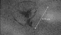
- FIG. 2 shows a photomicrograph of the surface of the crystallized glass plate damaged by the falling ball strength test having a drop height of 50 cm. There are minute cracks having a length of about 675 ⁇ m, which can be confirmed visually, but no cracking phenomenon is observed. The black portions in the figure are the same as in FIG. 3, but are minute voids caused by various cracks.
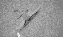
- FIG. 3 shows a photomicrograph of the surface of the chemically strengthened glass plate damaged in the falling ball strength test with a drop height of 3 cm. It can be seen that a deep crack having a length of about 600 ⁇ m, which causes a crack, is generated at the place where the sphere falls.
- the reason why the falling ball strength test has the configuration as described above is as follows.
- the glass starts at a relatively slow speed, starting from scratches that penetrate the compressive stress layer.
- slow crack cracking is generally a phenomenon in which there are few broken pieces, and most typically, one crack extends from the starting point of breakage and the cover glass is broken into two.
- the above-mentioned falling ball strength test is intended to make it possible to evaluate slow crack cracks, which has not been a problem in the past. That is, in the falling ball strength test, it is considered that the sharp start point such as sand contained in asphalt concrete is the starting point of breakage because the cover glass of the tablet PC is cracked by an impact that is not usually cracked.
- the falling ball strength test is performed in a state where a P30 sandpaper having an abrasive with an acute angle similar to that on the rubbing surface is placed on the sample.
- the transparent high-strength crystallized glass of the present invention is widely used in display devices, typically cover phones of small display devices such as mobile phones, personal digital assistants (PDAs), tablet personal computers with touch sensor functions, touch panels, etc. it can.
- display devices typically cover phones of small display devices such as mobile phones, personal digital assistants (PDAs), tablet personal computers with touch sensor functions, touch panels, etc. it can.
- PDAs personal digital assistants
- touch sensor functions touch panel, etc. it can.
Landscapes
- Chemical & Material Sciences (AREA)
- Engineering & Computer Science (AREA)
- Ceramic Engineering (AREA)
- Crystallography & Structural Chemistry (AREA)
- Dispersion Chemistry (AREA)
- Life Sciences & Earth Sciences (AREA)
- Chemical Kinetics & Catalysis (AREA)
- General Chemical & Material Sciences (AREA)
- Geochemistry & Mineralogy (AREA)
- Materials Engineering (AREA)
- Organic Chemistry (AREA)
- Glass Compositions (AREA)
- Re-Forming, After-Treatment, Cutting And Transporting Of Glass Products (AREA)
Abstract
高強度であり、かつ透明性を有する結晶化ガラスによるディスプレイ装置用カバーガラスの提供。 厚み1mmにおける波長400nmの光の透過率T400nmが10%超であるディスプレイ装置用結晶化ガラスであって、下記酸化物基準のモル%表示で、SiO2を61.5~72%、Al2O3を1~5.5%、P2O5を0.5~3%、ZrO2を0.5~3%、Li2Oを20~35%、K2Oを0~5%を含有し、P2O5およびZrO2の含有量の合計が1.7~5%であるガラスを結晶化して得られたディスプレイ装置用結晶化ガラス。
Description
本発明は、ディスプレイ装置、典型的には携帯電話、携帯情報端末(PDA)、タッチセンサ機能付タブレットパーソナルコンピュータ、タッチパネルなどの小型ディスプレイ装置のカバーガラスなどに好適な透明高強度結晶化ガラスに関する。
近年、携帯電話、PDA等のモバイル機器(携帯情報機器)に対しては、ディスプレイの保護ならびに美観を高めるためのカバーガラス(保護ガラス)が用いられることが多くなっている。
一方、このようなモバイル機器に対しては、軽量・薄型化が要求されている。そのため、ディスプレイ保護用に使用されるカバーガラスも薄くすることが要求されている。しかし、カバーガラスの厚さを薄くしていくと、強度が低下し、使用中または携帯中の落下などによりカバーガラス自身が割れてしまうことがあり、ディスプレイ装置を保護するという本来の役割を果たすことができなくなるという問題があった。
一方、このようなモバイル機器に対しては、軽量・薄型化が要求されている。そのため、ディスプレイ保護用に使用されるカバーガラスも薄くすることが要求されている。しかし、カバーガラスの厚さを薄くしていくと、強度が低下し、使用中または携帯中の落下などによりカバーガラス自身が割れてしまうことがあり、ディスプレイ装置を保護するという本来の役割を果たすことができなくなるという問題があった。
上記問題を解決するためには、カバーガラスの強度を高めることが要求され、その方法としてガラス表面に圧縮応力層を形成させる手法が一般的に知られている。
ガラス表面に圧縮応力層を形成させる手法としては、軟化点付近まで加熱したガラス板表面を風冷などにより急速に冷却する風冷強化法(物理強化法)と、ガラス転移点以下の温度でイオン交換によりガラス板表面のイオン半径が小さなアルカリ金属イオン(典型的にはLiイオン、Naイオン)をイオン半径のより大きいアルカリイオン(典型的にはKイオン)に交換する化学強化法が代表的である。
ガラス表面に圧縮応力層を形成させる手法としては、軟化点付近まで加熱したガラス板表面を風冷などにより急速に冷却する風冷強化法(物理強化法)と、ガラス転移点以下の温度でイオン交換によりガラス板表面のイオン半径が小さなアルカリ金属イオン(典型的にはLiイオン、Naイオン)をイオン半径のより大きいアルカリイオン(典型的にはKイオン)に交換する化学強化法が代表的である。
前述したようにカバーガラスの厚さは薄いことが要求されている。ところが薄いガラス板に対して風冷強化法を適用すると、表面と内部の温度差がつきにくいために圧縮応力層を形成することが困難であり、目的の高強度という特性を得ることができない。そのため、後者の化学強化法によって強化されたカバーガラスが通常用いられている(特許文献1参照)。
化学強化ガラスはディスプレイ装置のカバーガラスに用いられるような薄いガラスに適用可能であるが、携帯電話、PDAなど小型ディスプレイ装置のカバーガラスは軽量化のため、できるだけ薄く、かつ高強度なガラスが要求される。しかしながら、たとえば、1mmなど、通常の板厚であっても、内部に引張応力が蓄えられているため、割れるときには爆発的に割れる場合がある。
化学強化ガラスはディスプレイ装置のカバーガラスに用いられるような薄いガラスに適用可能であるが、携帯電話、PDAなど小型ディスプレイ装置のカバーガラスは軽量化のため、できるだけ薄く、かつ高強度なガラスが要求される。しかしながら、たとえば、1mmなど、通常の板厚であっても、内部に引張応力が蓄えられているため、割れるときには爆発的に割れる場合がある。
そのため、携帯電話、携帯情報端末(PDA)など小型ディスプレイ装置のカバーガラスに用いる際にそのような問題が起こらないようにするべく化学強化ガラスの強度を制限する提案がされている(特許文献2参照)。すなわち、特許文献2においては引張応力をガラス厚みによって特定される値以下とすることが提案されている。特許文献2においては、引張応力はガラス表面の圧縮応力CSに比例し、また、引張応力は圧縮応力層の深さをDOL、ガラス厚みをtとして(DOL-1・t-2)に反比例するとされているので、CSまたはDOLを小さくする方向性を提案していると言える。
先に述べた問題は化学強化ガラスのCSを大きくしようとすれば必然的に伴うものであって従来知られていたことであり、また、引張応力とCS、DOL、tとの関係を示す式も周知であった。
本発明は、化学強化ガラスのこのような問題を解決でき、しかも高強度であり、かつ透明性を有する結晶化ガラスによるディスプレイ装置のカバーガラスの提供などを目的とする。
本発明は、化学強化ガラスのこのような問題を解決でき、しかも高強度であり、かつ透明性を有する結晶化ガラスによるディスプレイ装置のカバーガラスの提供などを目的とする。
本発明は、下記酸化物基準のモル%表示で、SiO2を61.5~72%、Al2O3を1~5.5%、P2O5を0.5~3%、ZrO2を0.5~3%、Li2Oを20~35%、K2Oを0~5%を含有し、P2O5およびZrO2の含有量の合計P2O5+ZrO2が1.7~5%であるガラスを結晶化して得られたディスプレイ装置用結晶化ガラス(以下、結晶化ガラスAということがある。)を提供する。
また、厚み1mmにおける波長400nmの光の透過率T400nmが10%超であるディスプレイ装置用結晶化ガラスであって、下記酸化物基準のモル%表示で、SiO2を61.5~72%、Al2O3を1~5.5%、P2O5を0.5~3%、ZrO2を0.5~3%、Li2Oを20~35%、K2Oを0~5%を含有し、P2O5+ZrO2が1.7~5%であるガラスを結晶化して得られたディスプレイ装置用結晶化ガラスを提供する。
また、厚み1mmにおける波長400nmの光の透過率T400nmが10%超であるディスプレイ装置用結晶化ガラスであって、下記酸化物基準のモル%表示で、SiO2を61.5~72%、Al2O3を1~5.5%、P2O5を0.5~3%、ZrO2を0.5~3%、Li2Oを20~35%、K2Oを0~5%を含有し、P2O5+ZrO2が1.7~5%であるガラスを結晶化して得られたディスプレイ装置用結晶化ガラスを提供する。
また、前記ガラスのSiO2が62~68%、Al2O3が1~3%、P2O5が0.5~2%、ZrO2が0.5~2%、Li2Oが25~30%、K2Oが0~3.5%、P2O5+ZrO2が1.7~3.5%である前記ディスプレイ装置用結晶化ガラスを提供する。
前記ガラスのK2Oが0~2.5%である前記ディスプレイ装置用結晶化ガラスを提供する。
前記ガラスのK2Oが1%以上である前記ディスプレイ装置用結晶化ガラスを提供する。
また、前記ガラスのP2O5+ZrO2が2%以上である前記ディスプレイ装置用結晶化ガラスを提供する。
前記ガラスのK2Oが0~2.5%である前記ディスプレイ装置用結晶化ガラスを提供する。
前記ガラスのK2Oが1%以上である前記ディスプレイ装置用結晶化ガラスを提供する。
また、前記ガラスのP2O5+ZrO2が2%以上である前記ディスプレイ装置用結晶化ガラスを提供する。
また、結晶化してT400nmが10%超であるディスプレイ装置用結晶化ガラスとされるガラス組成物であって、下記酸化物基準のモル%表示で、SiO2を61.5~72%、Al2O3を1~5.5%、P2O5を0.5~3%、ZrO2を0.5~3%、Li2Oを20~35%、K2Oを0~5%を含有し、P2O5+ZrO2が1.7~5%であって着色成分を含有しないガラス組成物を提供する。
また、SiO2が62~68%、Al2O3が1~3%、P2O5が0.5~2%、ZrO2が0.5~2%、Li2Oが25~30%、K2Oが0~3.5%、P2O5+ZrO2が1.7~3.5%である前記着色成分を含有しないガラス組成物(以下、母ガラス1ということがある。)を提供する。
また、SiO2が62~68%、Al2O3が1~3%、P2O5が0.5~2%、ZrO2が0.5~2%、Li2Oが25~30%、K2Oが0~3.5%、P2O5+ZrO2が1.7~3.5%である前記着色成分を含有しないガラス組成物(以下、母ガラス1ということがある。)を提供する。
また、K2Oが1%以上である前記着色成分を含有しないガラス組成物を提供する。
また、P2O5+ZrO2が2%以上である前記着色成分を含有しないガラス組成物を提供する。
また、結晶化してディスプレイ装置用結晶化ガラスとされるガラス組成物であって、前記着色成分を含有しないガラス組成物に着色成分を含有させたガラス組成物(以下、母ガラス2ということがある。)を提供する。
また、前記着色成分を含有しないガラス組成物または前記着色成分を含有しないガラス組成物に着色成分を含有させたガラス組成物を結晶化して得られたディスプレイ装置用結晶化ガラスを提供する。
また、P2O5+ZrO2が2%以上である前記着色成分を含有しないガラス組成物を提供する。
また、結晶化してディスプレイ装置用結晶化ガラスとされるガラス組成物であって、前記着色成分を含有しないガラス組成物に着色成分を含有させたガラス組成物(以下、母ガラス2ということがある。)を提供する。
また、前記着色成分を含有しないガラス組成物または前記着色成分を含有しないガラス組成物に着色成分を含有させたガラス組成物を結晶化して得られたディスプレイ装置用結晶化ガラスを提供する。
また、Li2Si2O5結晶が析出している前記ディスプレイ装置用結晶化ガラスを提供する。
また、破壊靱性値Kcが1.2MPa・m1/2以上である前記ディスプレイ装置用結晶化ガラスを提供する。
また、T400nmが10%超である前記ディスプレイ装置用結晶化ガラスを提供する。
また、Li2Si2O5結晶が析出しており、破壊靱性値Kcが1.2MPa・m1/2以上、T400nmが10%超であるディスプレイ装置用結晶化ガラス(以下、結晶化ガラスBという。)を提供する。
また、厚み1mmにおける波長400~800nmの光の透過率が10%超である前記ディスプレイ装置用結晶化ガラスを提供する。
また、破壊靱性値Kcが1.2MPa・m1/2以上である前記ディスプレイ装置用結晶化ガラスを提供する。
また、T400nmが10%超である前記ディスプレイ装置用結晶化ガラスを提供する。
また、Li2Si2O5結晶が析出しており、破壊靱性値Kcが1.2MPa・m1/2以上、T400nmが10%超であるディスプレイ装置用結晶化ガラス(以下、結晶化ガラスBという。)を提供する。
また、厚み1mmにおける波長400~800nmの光の透過率が10%超である前記ディスプレイ装置用結晶化ガラスを提供する。
また、前記ディスプレイ装置用結晶化ガラスからなるカバーガラスを備えたディスプレイ装置を提供する。
また、前記ディスプレイ装置を備えたモバイル機器を提供する。
また、下記酸化物基準のモル%表示で、SiO2を61.5~72%、Al2O3を1~5.5%、P2O5を0.5~3%、ZrO2を0.5~3%、Li2Oを20~35%、K2Oを0~5%を含有し、P2O5+ZrO2が1~5%であるガラスであって結晶化第2ピーク温度T2が755℃超であるものを、そのガラス転移点をTgとして(Tg+40℃)~(Tg+100℃)の温度に1時間以上保持し、その後(T2-70℃)~(T2-5℃)の温度に1時間以上保持して結晶化することを特徴とする結晶化ガラスの製造方法を提供する。
また、前記ディスプレイ装置を備えたモバイル機器を提供する。
また、下記酸化物基準のモル%表示で、SiO2を61.5~72%、Al2O3を1~5.5%、P2O5を0.5~3%、ZrO2を0.5~3%、Li2Oを20~35%、K2Oを0~5%を含有し、P2O5+ZrO2が1~5%であるガラスであって結晶化第2ピーク温度T2が755℃超であるものを、そのガラス転移点をTgとして(Tg+40℃)~(Tg+100℃)の温度に1時間以上保持し、その後(T2-70℃)~(T2-5℃)の温度に1時間以上保持して結晶化することを特徴とする結晶化ガラスの製造方法を提供する。
また、下記酸化物基準のモル%表示で、SiO2を62~68%、Al2O3を1~3%、P2O5を0.5~2%、ZrO2を0.5~2%、Li2Oを25~30%、K2Oを0~2.5%を含有し、P2O5+ZrO2が1.5~3.5%であるガラスを、そのガラス転移点をTgとして(Tg+40℃)~(Tg+80℃)の温度に1時間以上保持し、その後750~820℃の温度に1時間以上保持して結晶化することを特徴とする結晶化ガラスの製造方法を提供する。
また、Tgが520℃未満である前記結晶化ガラスの製造方法を提供する。
また、Tgが520℃未満である前記結晶化ガラスの製造方法を提供する。
本発明によれば、高強度であり、かつ透明性を有する結晶化ガラスが提供され、この結晶化ガラスは、爆発的に割れる場合があるという化学強化ガラスの難点を回避することができる。
また、化学強化ガラスを厚さが0.4mm以下など特に薄いカバーガラスに用いようとすると内部引張応力が高くなりすぎるため、表面圧縮応力をあげることができない、あるいは表面圧縮層を所定の深さまで深くできない、などの問題が生じる。これに対し、本発明によれば結晶化ガラスをディスプレイ装置のカバーガラスに用いることができるので、カバーガラスを薄くしても高強度を維持することができる。
また、化学強化ガラスを厚さが0.4mm以下など特に薄いカバーガラスに用いようとすると内部引張応力が高くなりすぎるため、表面圧縮応力をあげることができない、あるいは表面圧縮層を所定の深さまで深くできない、などの問題が生じる。これに対し、本発明によれば結晶化ガラスをディスプレイ装置のカバーガラスに用いることができるので、カバーガラスを薄くしても高強度を維持することができる。
本発明のディスプレイ装置用結晶化ガラス(以下、本発明の結晶化ガラスという。)はLi2Si2O5結晶が析出しているものであることが好ましく、結晶化ガラスBにおいてはLi2Si2O5結晶が析出している。Li2Si2O5結晶が析出しているものでないと、高強度でありかつ透明性を有するものとなりにくい。
また、Li2Si2O5結晶が析出している結晶化ガラスである場合、主たる結晶相がLi2Si2O5結晶であることが好ましい。主たる結晶相とは、結晶が1種類しか析出していない場合は、その結晶のことを指し、結晶が複数析出している場合は、結晶の占める割合が多い結晶相を指す。通常、結晶析出の有無は粉末X線回折法で調べられ、結晶の占める割合は体積割合で表わされる。
また、Li2Si2O5結晶が析出している結晶化ガラスである場合、主たる結晶相がLi2Si2O5結晶であることが好ましい。主たる結晶相とは、結晶が1種類しか析出していない場合は、その結晶のことを指し、結晶が複数析出している場合は、結晶の占める割合が多い結晶相を指す。通常、結晶析出の有無は粉末X線回折法で調べられ、結晶の占める割合は体積割合で表わされる。
本発明の結晶化ガラスは、Li2Si2O5結晶の占める割合が50%以上であることが好ましい。Li2Si2O5結晶は、比較的透明性を維持しながら高強度を有するための結晶である。前記割合はより好ましくは60%以上、さらに好ましくは70%以上である。
同じLi2O-SiO2系の結晶としてLi2SiO3結晶があるが、Li2SiO3結晶が析出した場合、透明性は維持できるものの高強度になりにくい。Li2SiO3結晶の占める割合は20%以下が好ましく、10%以下がより好ましく、実質的に存在しないことが特に好ましい。
同じLi2O-SiO2系の結晶としてLi2SiO3結晶があるが、Li2SiO3結晶が析出した場合、透明性は維持できるものの高強度になりにくい。Li2SiO3結晶の占める割合は20%以下が好ましく、10%以下がより好ましく、実質的に存在しないことが特に好ましい。
本発明の結晶化ガラスは、LiAlSi4O10結晶などのLi2O-Al2O3-SiO2系の結晶が占める割合が20%以下であることが好ましい。Li2O-Al2O3-SiO2系の結晶としては、ペタライト、スポジュメン、ユークリプタイトなどがあるが、これらの結晶が析出した場合、透明性と高強度の少なくともどちらか一方が達成されにくい。上記割合は10%以下がより好ましく、実質的に存在しないことが特に好ましい。本発明の結晶化ガラスには典型的にはLiAlSi4O10結晶は析出していない。
結晶の占める割合は、以下のように測定する。結晶化ガラスを粉砕後、内部標準、例えば、α-石英を所定の割合混ぜたのち、粉末X線回折を測定する。得られた粉末X線回折データを粉末X線回折パターン総合解析ソフトウェア、例えば、RIGAKU社製JADEを用いて、各結晶相の割合を求める。実質的に存在しないとは、結晶相の割合が0となる場合である。
本発明の結晶化ガラスは、破壊靱性値Kcが1.2MPa・m1/2以上であることが好ましく、結晶化ガラスBにおいてはKcは1.2MPa・m1/2以上である。Kcが1.2MPa・m1/2未満だと、割れやすくなるおそれがある。Kcは典型的には1.25MPa・m1/2以上、より好ましくは1.3MPa・m1/2以上、さらに好ましくは1.5MPa・m1/2以上、特に好ましくは1.6MPa・m1/2以上である。一方、Kcは4.0以下が好ましく、3.0以下がより好ましい。Kcが4.0超では切断が極めて困難になるおそれがある。
Kcはたとえば次のように測定する。すなわち、JIS-R1607に基づきIF法により、ビッカース硬度計にて2kgf=19.6Nの荷重にて乾燥窒素雰囲気下でビッカース圧子を押し込み、クラックの長さと圧痕の長さを測定し、圧痕の長さからビッカース硬度を求め、次の式からKcを算出する。
Kc=0.018×(E/Hv)1/2×(P/C3/2)
ここでEはヤング率(GPa)、Hvはビッカース硬度(GPa)、Pは押し込み荷重(N)、Cはクラック長さの平均の半分(m)である。
Kc=0.018×(E/Hv)1/2×(P/C3/2)
ここでEはヤング率(GPa)、Hvはビッカース硬度(GPa)、Pは押し込み荷重(N)、Cはクラック長さの平均の半分(m)である。
本発明の結晶化ガラスは、波長400nmの光の厚さ1mm当たりの透過率T400nmが10%超であることが好ましく、結晶化ガラスBにおいては10%超である。T400nmが10%以下だと、散乱などにより透過光が少なくなり、ディスプレイ装置のカバーガラスなどとして用いた際に像が見えにくくなる。T400nmはより好ましくは30%以上、さらに好ましくは50%以上、特に好ましくは60%以上である。なお、本明細書で波長400nmの光の透過率を問題にするのは、ガラス中に結晶粒子が析出している透明結晶化ガラスでは通常400nmでの透過率が400~800nmの可視域で最も透過率が低く、したがって透明性の評価に最も適切であると考えるからである。
本発明の結晶化ガラスは、厚み1mmにおける波長400~800nmの光の透過率が10%超であることが好ましく、より好ましくは30%以上、さらに好ましくは50%以上、特に好ましくは60%以上である。
本発明の結晶化ガラスは、50~350℃における平均線膨張係数αが40×10-7/℃以上であることが好ましい。αが40×10-7/℃未満だと、フレームを含むディスプレイ装置部材との熱膨張係数差が大きく、ディスプレイ装置に応力を誘起し、ゆがみや表示ムラを起こす可能性があり、好ましくは50×10-7/℃以上である。また、αが80×10-7/℃以下であることが好ましい。αが80×10-7/℃超だと、ディスプレイ装置基板として用いられるガラス基板との熱膨張係数差が大きく、同様にゆがみや表示ムラを起こす可能性があり、好ましくは70×10-7/℃以下である。
本発明の結晶化ガラスは、50~350℃における平均線膨張係数αが40×10-7/℃以上であることが好ましい。αが40×10-7/℃未満だと、フレームを含むディスプレイ装置部材との熱膨張係数差が大きく、ディスプレイ装置に応力を誘起し、ゆがみや表示ムラを起こす可能性があり、好ましくは50×10-7/℃以上である。また、αが80×10-7/℃以下であることが好ましい。αが80×10-7/℃超だと、ディスプレイ装置基板として用いられるガラス基板との熱膨張係数差が大きく、同様にゆがみや表示ムラを起こす可能性があり、好ましくは70×10-7/℃以下である。
本発明の結晶化ガラスは、ヤング率Eが100GPa以上であることが好ましい。Eが100GPa未満だと、破壊靱性が小さくなり、強度が低下する可能性があり、より好ましくは105GPa以上である。またEは120GPa以下であることが好ましい。Eが120GPa超だと、脆さが大きくなり、クラックが発生しやすくなることから、加傷強度が低くなる可能性があり、より好ましくは110GPa以下である。
本発明の結晶化ガラスは、ビッカース硬度Hvが7GPa以上であることが好ましい。Hvが7GPa未満だと、物体との接触でキズが生成しやすくなる可能性があり、より好ましくは7.5GPa以上である。またHvは10GPa以下であることが好ましい。Hvが10GPa超だと、脆さが大きくなり、クラックが発生しやすくなることから、加傷強度が低くなる可能性があり、より好ましくは9GPa以下である。
次に、結晶化されて結晶化ガラスAが得られるところのガラス(以下、本発明のガラスということがあり、このような結晶化されるべきガラスを母ガラスという。)、母ガラス1および母ガラス2の組成について、モル百分率表示含有量を用いて説明する。本発明のガラスは本発明の結晶化ガラスの製造方法においても用いられるガラスである。そのガラス転移点Tgは典型的には520℃未満であり、たとえば400~510℃である。
次に、結晶化されて結晶化ガラスAが得られるところのガラス(以下、本発明のガラスということがあり、このような結晶化されるべきガラスを母ガラスという。)、母ガラス1および母ガラス2の組成について、モル百分率表示含有量を用いて説明する。本発明のガラスは本発明の結晶化ガラスの製造方法においても用いられるガラスである。そのガラス転移点Tgは典型的には520℃未満であり、たとえば400~510℃である。
SiO2は61.5%以上である。SiO2はガラスの骨格を構成する成分であり、本発明の結晶化ガラスの主たる結晶相として好ましいLi2Si2O5結晶の構成成分である。SiO2が61.5%未満ではガラスの粘性が低下し析出結晶を微細な結晶とするのが困難になる、または、Li2Si2O5結晶以外の結晶が析出しやすくなって高強度と透明性の両立が困難になるおそれがあり、好ましくは62%以上、より好ましくは63%以上、特に好ましくは64%以上、典型的には64.5%以上である。
SiO2は72%以下である。SiO2が72%超ではガラスの粘性が増大し溶融性が著しく低下する、石英などのSiO2結晶が析出しやすくなって高強度と透明性の両立が困難になるおそれがあり、好ましくは70%以下、さらに好ましくは68%以下、特に好ましくは67%以下、典型的には66.5%以下である。
SiO2は72%以下である。SiO2が72%超ではガラスの粘性が増大し溶融性が著しく低下する、石英などのSiO2結晶が析出しやすくなって高強度と透明性の両立が困難になるおそれがあり、好ましくは70%以下、さらに好ましくは68%以下、特に好ましくは67%以下、典型的には66.5%以下である。
Al2O3は1%以上であり、ガラスの分相を抑制し散乱による透明性悪化を防ぐ成分である。Al2O3が1%未満では透明性が低下するおそれがあり、好ましくは1.5%以上である。
Al2O3は5.5%以下である。Al2O3が5.5%超ではLi2O-Al2O3-SiO2系の結晶が多量に析出しやすくなり、透明性と高強度の両立が困難になるおそれがあり、好ましくは5%以下、より好ましくは4%以下、典型的には3%以下である。
P2O5は0.5%以上であり、核形成剤として寄与する成分である。P2O5が0.5%未満では析出結晶として微細な結晶が得にくくなり、透明性が低下するおそれがあり、好ましくは1%以上である。
Al2O3は5.5%以下である。Al2O3が5.5%超ではLi2O-Al2O3-SiO2系の結晶が多量に析出しやすくなり、透明性と高強度の両立が困難になるおそれがあり、好ましくは5%以下、より好ましくは4%以下、典型的には3%以下である。
P2O5は0.5%以上であり、核形成剤として寄与する成分である。P2O5が0.5%未満では析出結晶として微細な結晶が得にくくなり、透明性が低下するおそれがあり、好ましくは1%以上である。
P2O5は3%以下である。P2O5が3%超では、結晶化率が低下し、強度が低下するおそれがあり、好ましくは2.5%以下、典型的には2%以下である。
ZrO2は0.5%以上である。ZrO2は核形成剤として寄与する成分であり、0.5%未満では微細な結晶が得にくくなり、透明性が低下するおそれがある。ZrO2は好ましくは1%以上である。
ZrO2は3%以下であることが好ましい。ZrO2が3%超では、ZrO2結晶が析出しやすくなり、透明性が悪化するおそれがあり、好ましくは2.5%以下、より好ましくは2%以下、典型的には1.8%以下である。
ZrO2は0.5%以上である。ZrO2は核形成剤として寄与する成分であり、0.5%未満では微細な結晶が得にくくなり、透明性が低下するおそれがある。ZrO2は好ましくは1%以上である。
ZrO2は3%以下であることが好ましい。ZrO2が3%超では、ZrO2結晶が析出しやすくなり、透明性が悪化するおそれがあり、好ましくは2.5%以下、より好ましくは2%以下、典型的には1.8%以下である。
P2O5およびZrO2の含有量の合計P2O5+ZrO2は1.7%以上である。P2O5およびZrO2はいずれも核形成剤として寄与する成分であるが、両者を共存させることにより、析出結晶としてより微細な結晶が得やすくなる。その合計が1.7%未満では、結晶化率が低下して所望の強度が得にくくなる、あるいは温度を上げて結晶化率を上げようとすると透明性が得られないおそれがあり、好ましくは2%以上である。
P2O5+ZrO2は5%以下である。P2O5+ZrO2が5%超では均質性が悪化し、透明性が悪化するおそれがあり、好ましくは4.5%以下、さらに好ましくは4%以下、典型的には3.5%以下である。
P2O5+ZrO2は5%以下である。P2O5+ZrO2が5%超では均質性が悪化し、透明性が悪化するおそれがあり、好ましくは4.5%以下、さらに好ましくは4%以下、典型的には3.5%以下である。
Li2Oは20%以上である。Li2Oは本発明の結晶化ガラスの主たる結晶相として好ましいLi2Si2O5結晶の構成成分であり、20%未満ではLi2Si2O5結晶が析出しにくくなり、高強度と透明性の両立が困難になるおそれがあり、好ましくは23%以上、特に好ましくは25%以上である。
Li2Oは35%以下である。Li2Oが35%超では、ガラスの粘性が低下し析出結晶を微細な結晶とするのが困難になり、透明性が悪化するおそれがあり、好ましくは30%以下、典型的には28.5%以下である。
Li2Oは35%以下である。Li2Oが35%超では、ガラスの粘性が低下し析出結晶を微細な結晶とするのが困難になり、透明性が悪化するおそれがあり、好ましくは30%以下、典型的には28.5%以下である。
K2OはクリストバライトなどのSiO2結晶の析出を抑制し、高強度と透明性を両立しやすくする成分であり、必須ではないが添加してもよい任意成分である。K2Oを添加する場合は、0.5%以上であることが好ましく、より好ましくは1%以上である。失透をしにくくさせてガラスの成形性を向上させたい場合などにはK2Oは2%以上であることが好ましく、2.5%以上であることがより好ましい。
K2Oは含有する場合であってもその含有量は5%以下である。5%超ではLi2Si2O5結晶が析出しにくくなり、高強度と透明性の両立が困難になるおそれがある。より好ましくは4%以下、典型的には3.5%以下である。強度を向上させたい場合などにはK2Oは3%以下であることが好ましく、典型的には2.5%以下である。
K2Oは含有する場合であってもその含有量は5%以下である。5%超ではLi2Si2O5結晶が析出しにくくなり、高強度と透明性の両立が困難になるおそれがある。より好ましくは4%以下、典型的には3.5%以下である。強度を向上させたい場合などにはK2Oは3%以下であることが好ましく、典型的には2.5%以下である。
SiとLiの原子数比SiO2/(Li2O/2)は1.0以上であることが好ましい。同比が1.0未満では本発明の結晶化ガラスの主たる結晶相として好ましいLi2Si2O5結晶を析出した時の残存ガラス相に、ガラスの骨格を構成する成分であるSiO2の割合が少なくなり、高強度が得られなくなるおそれがあり、好ましくは、1.1以上、より好ましくは1.2以上である。一方、好ましくは、1.8以下、より好ましくは1.6以下である。同比が1.8超では、結晶の占める割合が低下し、強度が低下する。
SiとLiの原子数比とP2O5+ZrO2の積(P2O5+ZrO2)×SiO2/(Li2O/2)は2.8~3.8%であることが好ましい。同積が2.8%未満では結晶の析出が不十分となって高強度が得られなくなるおそれがあり、より好ましくは3.0以上、より好ましくは3.1以上であり、3.8%超ではガラスが分相し高透過が得られなくなるおそれがあり、より好ましくは3.6%以下ある。
SiとLiの原子数比とP2O5+ZrO2の積(P2O5+ZrO2)×SiO2/(Li2O/2)は2.8~3.8%であることが好ましい。同積が2.8%未満では結晶の析出が不十分となって高強度が得られなくなるおそれがあり、より好ましくは3.0以上、より好ましくは3.1以上であり、3.8%超ではガラスが分相し高透過が得られなくなるおそれがあり、より好ましくは3.6%以下ある。
本発明のガラスの典型的な態様として、SiO2が62~68%、Al2O3が1~3%、P2O5が0.5~2%、ZrO2が0.5~2%、Li2Oが25~30%、K2Oが0~2.5%、P2O5+ZrO2が1.7~3.5%であるものが挙げられる。
本発明のガラスは本質的に上記成分からなるが本発明の目的を損なわない範囲でそれ以外の成分を含有してもよい。その場合そのような成分の含有量の合計は好ましくは5%以下であり、より好ましくは3%以下、典型的には1%未満である。
たとえば、In2O3、Ga2O3、SnO2、BaOを含有する場合はそれぞれ1%以下、1%以下、2%以下、1%以下であることが好ましい。また、La2O3を含有する場合は0.4%以下でなければ本発明の目的が損なわれる場合がある。
本発明のガラスは本質的に上記成分からなるが本発明の目的を損なわない範囲でそれ以外の成分を含有してもよい。その場合そのような成分の含有量の合計は好ましくは5%以下であり、より好ましくは3%以下、典型的には1%未満である。
たとえば、In2O3、Ga2O3、SnO2、BaOを含有する場合はそれぞれ1%以下、1%以下、2%以下、1%以下であることが好ましい。また、La2O3を含有する場合は0.4%以下でなければ本発明の目的が損なわれる場合がある。
母ガラス1は本質的に上記成分からなるが本発明の目的を損なわない範囲でそれ以外の成分であって着色成分でないものを含有してもよい。その場合そのような成分の含有量の合計は好ましくは5%以下であり、より好ましくは3%以下、典型的には1%未満である。本発明でいう着色成分とは通常ガラスを着色する成分として知られているものであってこれまでに挙げた成分以外のものをいう。たとえば、Fe、Ni、Cr、Co、Cu、Ti、V、Mn、Mo、Ag、Au、Ptなどの遷移金属、Ce、Nd、Sm、Er、Tm、Prなどの希土類元素、Se、Cdなど、またはそれらの酸化物が挙げられる。典型的にはFe、Ni、Cr、Co、Cu、Ti、V、Mn、Mo、Ce、Nd、Sm、Er、Tm、Pr、Cu、Ag、Au、Pt、Se、およびCdからなる群から選ばれる1以上の金属または同群から選ばれる1以上の金属の酸化物である。
母ガラス2は本質的に上記成分からなり、母ガラス1に着色成分を含有させたものである。
母ガラス2は本質的に上記成分からなり、母ガラス1に着色成分を含有させたものである。
次に、本発明の結晶化ガラスを製造する方法について例示的に説明する。
まず、所定の組成となるようにガラス原料を調合し、均一に混合した後、ガラス原料を溶融炉にて溶融する。清澄剤としては、SO3、SnO2、Clなど周知の清澄剤を少なくとも1種類以上使用する。溶融温度はたとえば1200~1780℃であり、設備の負荷を抑えたい場合などには1250~1650℃が好ましく、生産性を高くしたい場合などには500~1780℃が好ましく、より好ましくは1550~1750℃であり、これらの温度でたとえば2~24時間溶融を行う。なお、ガラス溶融時に減圧しながら脱泡してもよい。その後成形、徐冷を行い、母ガラスとする。なお、この母ガラスは本発明のガラスである。
得られた母ガラスを熱処理(結晶化)することによって結晶化ガラスを得る。熱処理は、結晶核生成と結晶成長の2段階とすることが好ましい。本発明の結晶化ガラスの製造方法はそのようなものである。
まず、所定の組成となるようにガラス原料を調合し、均一に混合した後、ガラス原料を溶融炉にて溶融する。清澄剤としては、SO3、SnO2、Clなど周知の清澄剤を少なくとも1種類以上使用する。溶融温度はたとえば1200~1780℃であり、設備の負荷を抑えたい場合などには1250~1650℃が好ましく、生産性を高くしたい場合などには500~1780℃が好ましく、より好ましくは1550~1750℃であり、これらの温度でたとえば2~24時間溶融を行う。なお、ガラス溶融時に減圧しながら脱泡してもよい。その後成形、徐冷を行い、母ガラスとする。なお、この母ガラスは本発明のガラスである。
得られた母ガラスを熱処理(結晶化)することによって結晶化ガラスを得る。熱処理は、結晶核生成と結晶成長の2段階とすることが好ましい。本発明の結晶化ガラスの製造方法はそのようなものである。
結晶核生成のための熱処理は、そのガラスのガラス転移点をTgとして、(Tg+40℃)~(Tg+100℃)の温度範囲にて行うことが好ましい。(Tg+100℃)超の温度では、結晶成長が生じるため、結晶が粗大化する、不均質になるなどにより透明性が悪化するおそれがあり、典型的には(Tg+80℃)以下である。温度が(Tg+40℃)未満では結晶核生成が不十分となり、透明性と強度の両立が困難になるおそれがある。
結晶核生成のための熱処理時間は1時間以上であることが好ましい。1時間未満では、結晶核生成が不十分となり、透明性と強度の両立が困難になるおそれがある。より好ましくは2時間以上または3時間以上である。また、結晶核生成のための熱処理時間は24時間以下であることが好ましい。24時間超では結晶成長が不均質になるなどにより透明性が悪化するおそれがある。より好ましくは12時間以下である。
また、結晶核生成のための熱処理は、上記好ましい結晶核生成のための熱処理であって、そのガラスを10℃/分にて測定した場合の示差熱分析の結晶化第1ピーク温度をT1として、(T1-50℃)以下の温度にて行うものであることがより好ましい。本発明の結晶化ガラスでは、結晶化第1ピーク温度にて析出する結晶がLi2SiO3である可能性が高く、(T1-50℃)超の温度で熱処理を行うと、Li2SiO3が多量に析出し、透明性と強度の少なくとも一方を損なわせる可能性がある。
また、結晶核生成のための熱処理は、上記好ましい結晶核生成のための熱処理であって、そのガラスを10℃/分にて測定した場合の示差熱分析の結晶化第1ピーク温度をT1として、(T1-50℃)以下の温度にて行うものであることがより好ましい。本発明の結晶化ガラスでは、結晶化第1ピーク温度にて析出する結晶がLi2SiO3である可能性が高く、(T1-50℃)超の温度で熱処理を行うと、Li2SiO3が多量に析出し、透明性と強度の少なくとも一方を損なわせる可能性がある。
結晶成長のための熱処理は、そのガラスを10℃/分にて測定した場合の示差熱分析の結晶化第2ピーク温度をT2としてT2が755℃超である場合、(T2-70℃)~(T2-5℃)の温度範囲にて行うことが好ましい。(T2-70℃)未満の温度では、結晶化率が低くなり、高強度が得にくいおそれがある。また、結晶成長のための熱処理は、(T2-5℃)以下であることが好ましい。(T2-5℃)超だと透明性が得にくくなるおそれがある。この場合、Li2SiO3の析出を抑制する観点からは、T2は好ましくは790℃以上、より好ましくは820℃以上である。
また、結晶成長のための熱処理は、750℃~850℃の温度範囲で行うことが好ましい。温度が750℃未満では、Li2SiO3が多量に析出して透明性と強度の少なくとも一方が損なわれるおそれがあり、より好ましくは770℃以上である。温度が850℃超では結晶サイズが大きくなって透明性が損なわれるおそれがあり、より好ましくは830℃以下、さらに好ましくは820℃以下である。
結晶成長のための熱処理時間は1時間以上であることが好ましい。熱処理時間が1時間未満では、結晶化率が低くなり、高強度が得にくくなるおそれがあり、より好ましくは1.5時間以上である。また、結晶成長のための熱処理時間は24時間以下であることが好ましい。熱処理時間が24時間超だと透明性が得にくくなるおそれがあり、より好ましくは12時間以下、特に好ましくは6時間以下である。
結晶成長のための熱処理時間は1時間以上であることが好ましい。熱処理時間が1時間未満では、結晶化率が低くなり、高強度が得にくくなるおそれがあり、より好ましくは1.5時間以上である。また、結晶成長のための熱処理時間は24時間以下であることが好ましい。熱処理時間が24時間超だと透明性が得にくくなるおそれがあり、より好ましくは12時間以下、特に好ましくは6時間以下である。
ガラスの示差熱分析の結晶化第1ピーク温度T1および結晶化第2ピーク温度T2は次のように測定する。すなわち、本発明の結晶化ガラスの母ガラスを粉砕し、ふるいを用いて粒径が44μmと53μmの間に入るものだけを抽出し、昇温速度10℃/分にて示差熱分析装置を用いて測定する。
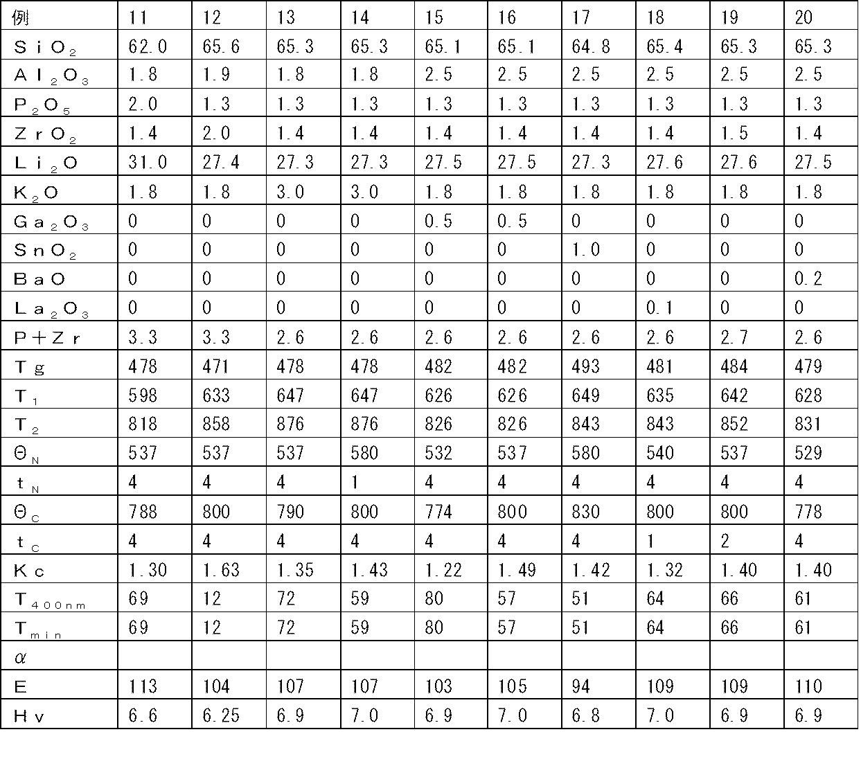
表1~4の例1~23、28~39のSiO2からLa2O3またはK2Oまでの欄にモル%表示で示す組成になるように、酸化物、水酸化物、炭酸塩、硫酸塩等一般に使用されているガラス原料を適宜選択し、ガラスとして300gとなるように秤量および混合した。ついで、白金製るつぼに入れ、1600℃の抵抗加熱式電気炉に投入し、3時間溶融し、脱泡、均質化した後、型材に流し込み、ガラス転移点から30℃程度高い温度にて1時間保持後、毎分1℃の冷却速度にて室温まで冷却してこれら例のガラスを得た。なお、表中の「P+Zr」はP2O5+ZrO2を略記したものである。
これらガラスのガラス転移点Tg(単位:℃)、結晶化第1ピーク温度T1(単位:℃)、結晶化第2ピーク温度T2(単位:℃)を次のようにして測定した。結果を表1~4の該当欄に示す。なお、例10、21、22のTgは計算によって求めた値である。
Tg:得られたガラスの一部を用いて直径5mm、長さ20mmの円柱状サンプルを作製し、ブルカー・エイエックスエス社製熱膨張計TD5010SAを用いて5℃/分の昇温速度で測定し、ガラス転移点を求めた。
Tg:得られたガラスの一部を用いて直径5mm、長さ20mmの円柱状サンプルを作製し、ブルカー・エイエックスエス社製熱膨張計TD5010SAを用いて5℃/分の昇温速度で測定し、ガラス転移点を求めた。
T1、T2: 得られたガラスの一部を粉砕し、ふるいを用いて粒径が44μmと53μmの間に入るものだけを抽出した。この抽出されたガラス粉末を昇温速度10℃/分にてブルカー・エイエックスエス社製示差熱分析装置TG-DTA2020SAを用いて、結晶化第1ピーク温度T1および結晶化第2ピーク温度T2を読み取った。なお、ピーク温度はピークの最高地点すなわち最高点になるところの温度である。
次いで、これらガラスを表のΘNに示す核生成熱処理温度(単位:℃)にてtNに示す核生成熱処理時間(単位:時間)保持したのち、ΘCに示す結晶成長熱処理温度(単位:℃)にてtCに示す結晶成長熱処理時間(単位:時間)保持し、その後室温まで冷却して結晶化ガラスを作製した。熱処理時の加熱、冷却はともに毎分10℃の速度にて行った。なお、例31についてはΘNまでは150℃/時間、ΘNからΘCまでは150℃/時間の速度で昇温した。
次いで、これらガラスを表のΘNに示す核生成熱処理温度(単位:℃)にてtNに示す核生成熱処理時間(単位:時間)保持したのち、ΘCに示す結晶成長熱処理温度(単位:℃)にてtCに示す結晶成長熱処理時間(単位:時間)保持し、その後室温まで冷却して結晶化ガラスを作製した。熱処理時の加熱、冷却はともに毎分10℃の速度にて行った。なお、例31についてはΘNまでは150℃/時間、ΘNからΘCまでは150℃/時間の速度で昇温した。
得られた結晶化ガラスについて析出結晶を、CuKα線を用いる粉末X線回折法で調べた結果、例1~23、28~37、39のいずれについても主たる結晶すなわち回折ピーク強度が最も大きい析出結晶はLi2Si2O5結晶であり、その他の結晶の回折ピークは認められなかった。例38についてもLi2Si2O5結晶の析出が認められたが主たる結晶はLiAlSi4O10結晶であり、それら以外の結晶の回折ピークは認められなかった。
また、得られた結晶化ガラスについて破壊靭性値Kc(単位:MPa・m1/2)、厚み1mmにおける波長400nmの光の透過率T400nm(単位:%)、厚み1mmにおける波長400~800nmの光の透過率の最小値Tmin(単位:%)、50~350℃における平均線膨張係数α(単位:10-7/℃)、ヤング率E(単位:GPa)およびビッカース硬度Hv(単位:GPa)を次のようにして測定した。結果を表1~4の該当欄に示す。なお、例2~5、7、9、10、14、18、19、21~23のHvは計算によって求めた値である。
Kc:JIS-R1607に基づき、約20mm×約20mm×厚さ約1mmで、上下面が鏡面加工された板状サンプルを作製し、ビッカース硬度計にて2kgfの荷重でビッカース圧子を押し込み、先に述べたようにIF法により破壊靱性値を求めた。
T400nm、Tmin:約20mm×約20mm×厚さ約1mmで、上下面が鏡面加工された板状サンプルを作製し、パーキン・エルマー社製紫外可視近赤外分光光度計Lambda950を用いて波長400~800nmの分光透過率曲線を取得し、波長400nmの光の厚さ1mm当たりの透過率およびこの波長範囲の透過率の最小値を求めた。なお、いずれのサンプルの分光透過率曲線においても透過率が最小となる波長は400nmであった。
T400nm、Tmin:約20mm×約20mm×厚さ約1mmで、上下面が鏡面加工された板状サンプルを作製し、パーキン・エルマー社製紫外可視近赤外分光光度計Lambda950を用いて波長400~800nmの分光透過率曲線を取得し、波長400nmの光の厚さ1mm当たりの透過率およびこの波長範囲の透過率の最小値を求めた。なお、いずれのサンプルの分光透過率曲線においても透過率が最小となる波長は400nmであった。
α:直径5mm、長さ20mmの円柱状サンプルを作製し、ブルカー・エイエックスエス社製熱膨張計TD5010SAを用いて5℃/分の昇温速度で測定し、50~350℃における平均線膨張係数を求めた。
E:4cm×4cmのガラス板を作製しその両面が平行になるように研磨して、厚さを10mm程度とした試料について、超音波パルス法によりヤング率を測定した。
Hv:約20mm×約20mm×厚さ約1mmで、上下面が鏡面加工された板状サンプルを作製し、ビッカース硬度計にて100gfの荷重でビッカース圧子を押し込み、ビッカース硬度を求めた。
例1~23は実施例、例28~39は比較例または参考例である。例24~27もKcおよびT400nmまたはTminが大きい本発明の実施例であり、例40は比較例である。
E:4cm×4cmのガラス板を作製しその両面が平行になるように研磨して、厚さを10mm程度とした試料について、超音波パルス法によりヤング率を測定した。
Hv:約20mm×約20mm×厚さ約1mmで、上下面が鏡面加工された板状サンプルを作製し、ビッカース硬度計にて100gfの荷重でビッカース圧子を押し込み、ビッカース硬度を求めた。
例1~23は実施例、例28~39は比較例または参考例である。例24~27もKcおよびT400nmまたはTminが大きい本発明の実施例であり、例40は比較例である。



また、大きさが50mm×50mm、厚みが0.6mmである例1の結晶化ガラス板と、モル百分率表示組成がSiO2:73%、Al2O3:7%、MgO:6%、Na2O:14%であり、大きさが50mm×50mm、厚みが0.6mmであるガラス板を425℃の硝酸カリウムに11時間40分間浸漬してイオン交換した化学強化ガラス板を用意した。
これら結晶化ガラス板および化学強化ガラス板を試料として、サンドペーパーを用いる次のような落球強度試験を行った。すなわち、試料を花崗岩からなる基台上に載せ、その試料の上面にP30(JIS R6252:2006年)のサンドペーパーをその擦り面が下になるようにして試料の上に載せた状態で、サンドペーパーの上面に直径0.75インチ、質量28gのステンレス鋼の球を落下させ、試料が破壊する落下高さを測定した。なお、結晶化ガラス板については、破壊していないがその表面に目視で確認できる傷がついた状態が認められたときの落下高さを測定した。
これら結晶化ガラス板および化学強化ガラス板を試料として、サンドペーパーを用いる次のような落球強度試験を行った。すなわち、試料を花崗岩からなる基台上に載せ、その試料の上面にP30(JIS R6252:2006年)のサンドペーパーをその擦り面が下になるようにして試料の上に載せた状態で、サンドペーパーの上面に直径0.75インチ、質量28gのステンレス鋼の球を落下させ、試料が破壊する落下高さを測定した。なお、結晶化ガラス板については、破壊していないがその表面に目視で確認できる傷がついた状態が認められたときの落下高さを測定した。
この測定を各10回繰り返し落下高さの平均を計算したところ、化学強化ガラス板が破壊する落下高さは3cmであったのに対し、結晶化ガラス板は落下高さが43cmで傷がつくが破壊することはなく非常に強い強度を示した。なお、この化学強化ガラス板について落下高さ40cmの落球強度試験を行うと50個以上の破片となってそれらが約50cm四方に飛び散る。
図2に落下高さ50cmの落球強度試験で傷ついた結晶化ガラス板表面の顕微鏡写真を示す。約675μmの長さの微小なクラックが存在し、これは目視でも確認できるが、割れ現象は認められない。図中の黒く見える部分は、図3でも同じであるが、種々のクラックによって生じた微小な空隙である。
これに対し、図3に落下高さ3cmの落球強度試験で傷ついた化学強化ガラス板表面の顕微鏡写真を示す。球の落下場所に割れの原因となる約600μmの長さの深いクラックが発生していることがわかる。
このように本発明の結晶化ガラスを用いれば化学強化ガラス板であれば割れてしまうような衝撃が加わっても割れることはなく、また傷もつきにくい。このことからも、ディスプレイ装置の保護に用いられる本発明の結晶化ガラスの効用がわかる。
これに対し、図3に落下高さ3cmの落球強度試験で傷ついた化学強化ガラス板表面の顕微鏡写真を示す。球の落下場所に割れの原因となる約600μmの長さの深いクラックが発生していることがわかる。
このように本発明の結晶化ガラスを用いれば化学強化ガラス板であれば割れてしまうような衝撃が加わっても割れることはなく、また傷もつきにくい。このことからも、ディスプレイ装置の保護に用いられる本発明の結晶化ガラスの効用がわかる。
なお、前記落球強度試験が先に述べたような構成を有するのは次のような理由による。
使用者がフラットパネルディスプレイ装置を誤って落下させた場合などカバーガラスに衝撃を与えた際に、化学強化したカバーガラスであっても、圧縮応力層を突き抜ける傷を起点にガラスが比較的遅い速度で割れるスロークラックが生じることがある(以下、このようなガラスの割れ方をスロークラック割れと呼ぶ。)。なお、このスロークラック割れは、一般的に割れ破片が少なく、最も典型的には破壊起点から一本のクラックが延びてカバーガラスが2つに割れる現象である。
特に、立てかけて使用することの多いタッチセンサ機能付タブレットPCにおいては、使用者が誤ってタッチセンサ機能付タブレットPCを倒してしまった場合など通常は割れるほどではない衝撃をカバーガラスに与えた際に、化学強化したカバーガラスであっても、割れが発生することが報告されている。この割れはスロークラック割れであると考えられる。
使用者がフラットパネルディスプレイ装置を誤って落下させた場合などカバーガラスに衝撃を与えた際に、化学強化したカバーガラスであっても、圧縮応力層を突き抜ける傷を起点にガラスが比較的遅い速度で割れるスロークラックが生じることがある(以下、このようなガラスの割れ方をスロークラック割れと呼ぶ。)。なお、このスロークラック割れは、一般的に割れ破片が少なく、最も典型的には破壊起点から一本のクラックが延びてカバーガラスが2つに割れる現象である。
特に、立てかけて使用することの多いタッチセンサ機能付タブレットPCにおいては、使用者が誤ってタッチセンサ機能付タブレットPCを倒してしまった場合など通常は割れるほどではない衝撃をカバーガラスに与えた際に、化学強化したカバーガラスであっても、割れが発生することが報告されている。この割れはスロークラック割れであると考えられる。
従来問題にされていなかったスロークラック割れも評価できるようにすることを目的としたものが前記落球強度試験である。すなわち、前記落球強度試験は、タブレットPCのカバーガラスが通常は割れるほどではない衝撃で割れるのはアスファルトコンクリートに含まれる砂など鋭角形状のものが破壊起点となっていると考え、そのような砂と同様の鋭角度合いの研磨材をその擦り面に有するP30のサンドペーパーを試料に載せた状態で落球強度試験を行うようにしたものである。
本発明の透明高強度結晶化ガラスは、ディスプレイ装置、典型的には携帯電話、携帯情報端末(PDA)、タッチセンサ機能付タブレットパーソナルコンピュータ、タッチパネルなどの小型ディスプレイ装置のカバーガラスなどに広範に使用できる。
なお、2011年3月4日に出願された日本特許出願2011-047828号の明細書、特許請求の範囲、図面及び要約書の全内容をここに引用し、本発明の明細書の開示として、取り入れるものである。
Claims (20)
- 厚み1mmにおける波長400nmの光の透過率T400nmが10%超であるディスプレイ装置用結晶化ガラスであって、下記酸化物基準のモル%表示で、SiO2を61.5~72%、Al2O3を1~5.5%、P2O5を0.5~3%、ZrO2を0.5~3%、Li2Oを20~35%、K2Oを0~5%を含有し、P2O5およびZrO2の含有量の合計(P2O5+ZrO2)が1.7~5%であるガラスを結晶化して得られたディスプレイ装置用結晶化ガラス。
- 前記ガラスのSiO2が62~68%、Al2O3が1~3%、P2O5が0.5~2%、ZrO2が0.5~2%、Li2Oが25~30%、K2Oが0~3.5%、P2O5+ZrO2が1.5~3.5%である請求項1に記載のディスプレイ装置用結晶化ガラス。
- 前記ガラスのK2Oが0~2.5%である請求項1または2に記載のディスプレイ装置用結晶化ガラス。
- 前記ガラスのK2Oが1%以上である請求項1、2または3に記載のディスプレイ装置用結晶化ガラス。
- 前記ガラスのP2O5+ZrO2が2%以上である請求項1~4のいずれかに記載のディスプレイ装置用結晶化ガラス。
- 結晶化して厚み1mmにおける波長400nmの光の透過率T400nmが10%超であるディスプレイ装置用結晶化ガラスとされるガラス組成物であって、下記酸化物基準のモル%表示で、SiO2を61.5~72%、Al2O3を1~5.5%、P2O5を0.5~3%、ZrO2を0.5~3%、Li2Oを20~35%、K2Oを0~5%を含有し、P2O5およびZrO2の含有量の合計(P2O5+ZrO2)が1.7~5%であって着色成分を含有しないガラス組成物。
- SiO2が62~68%、Al2O3が1~3%、P2O5が0.5~2%、ZrO2が0.5~2%、Li2Oが25~30%、K2Oが0~3.5%、P2O5+ZrO2が1.7~3.5%である請求項6に記載のガラス組成物。
- K2Oが1%以上である請求項6または7に記載のガラス組成物。
- P2O5+ZrO2が2%以上である請求項6、7または8に記載のガラス組成物。
- 結晶化してディスプレイ装置用結晶化ガラスとされるガラス組成物であって、請求項6~9のいずれかに記載のガラス組成物に着色成分を含有させたガラス組成物。
- 請求項6~10のいずれかに記載のガラス組成物を結晶化して得られたディスプレイ装置用結晶化ガラス。
- Li2Si2O5結晶が析出している請求項1、2、3、4、5または11に記載のディスプレイ装置用結晶化ガラス。
- 破壊靱性値Kcが1.2MPa・m1/2以上である請求項1、2、3、4、5、11または12に記載のディスプレイ装置用結晶化ガラス。
- 厚み1mmにおける波長400~800nmの光の透過率が50%超である請求項1、2、3、4、5、11、12または13に記載のディスプレイ装置用結晶化ガラス。
- 厚み1mmにおける波長400nmの光の透過率が50%超である請求項1、2、3、4、5、11、12、13または14に記載のディスプレイ装置用結晶化ガラス。
- 請求項1~5又は11~15のいずれかに記載のディスプレイ装置用結晶化ガラスからなるカバーガラスを備えたディスプレイ装置。
- 請求項16に記載のディスプレイ装置を備えたモバイル機器。
- 下記酸化物基準のモル%表示で、SiO2を61.5~72%、Al2O3を1~5.5%、P2O5を0.5~3%、ZrO2を0.5~3%、Li2Oを20~35%、K2Oを0~5%を含有し、P2O5およびZrO2の含有量の合計(P2O5+ZrO2)が1~5%であるガラスであって結晶化第2ピーク温度T2が755℃超であるものを、そのガラス転移点をTgとして(Tg+40℃)~(Tg+100℃)の温度に1時間以上保持し、その後(T2-70℃)~(T2-5℃)の温度に1時間以上保持して結晶化することを特徴とする結晶化ガラスの製造方法。
- 下記酸化物基準のモル%表示で、SiO2を62~68%、Al2O3を1~3%、P2O5を0.5~2%、ZrO2を0.5~2%、Li2Oを25~30%、K2Oを0~2.5%を含有し、P2O5およびZrO2の含有量の合計(P2O5+ZrO2)が1.5~3.5%であるガラスを、そのガラス転移点をTgとして(Tg+40℃)~(Tg+80℃)の温度に1時間以上保持し、その後750~820℃の温度に1時間以上保持して結晶化することを特徴とする結晶化ガラスの製造方法。
- Tgが520℃未満である請求項18または19に記載の結晶化ガラスの製造方法。
Priority Applications (1)
| Application Number | Priority Date | Filing Date | Title |
|---|---|---|---|
| JP2013503489A JPWO2012121116A1 (ja) | 2011-03-04 | 2012-03-01 | ディスプレイ装置用結晶化ガラス |
Applications Claiming Priority (2)
| Application Number | Priority Date | Filing Date | Title |
|---|---|---|---|
| JP2011047828 | 2011-03-04 | ||
| JP2011-047828 | 2011-03-04 |
Publications (1)
| Publication Number | Publication Date |
|---|---|
| WO2012121116A1 true WO2012121116A1 (ja) | 2012-09-13 |
Family
ID=46798082
Family Applications (1)
| Application Number | Title | Priority Date | Filing Date |
|---|---|---|---|
| PCT/JP2012/055279 Ceased WO2012121116A1 (ja) | 2011-03-04 | 2012-03-01 | ディスプレイ装置用結晶化ガラス |
Country Status (3)
| Country | Link |
|---|---|
| JP (1) | JPWO2012121116A1 (ja) |
| TW (1) | TW201245073A (ja) |
| WO (1) | WO2012121116A1 (ja) |
Cited By (14)
| Publication number | Priority date | Publication date | Assignee | Title |
|---|---|---|---|---|
| US9308616B2 (en) | 2013-01-21 | 2016-04-12 | Innovative Finishes LLC | Refurbished component, electronic device including the same, and method of refurbishing a component of an electronic device |
| KR20170060156A (ko) * | 2014-10-08 | 2017-05-31 | 코닝 인코포레이티드 | 페탈라이트 및 리튬 실리케이트 구조를 갖는 고강도 유리-세라믹 |
| US20200017399A1 (en) * | 2018-07-16 | 2020-01-16 | Corning Incorporated | Glass-ceramic articles with increased resistance to fracture and methods for making the same |
| CN112321162A (zh) * | 2020-11-13 | 2021-02-05 | 重庆鑫景特种玻璃有限公司 | 蓝紫光低透过率玻璃陶瓷及其制备方法、玻璃制品 |
| CN112512985A (zh) * | 2018-08-09 | 2021-03-16 | 株式会社小原 | 结晶化玻璃基板 |
| JP2021531229A (ja) * | 2018-07-16 | 2021-11-18 | コーニング インコーポレイテッド | 改善された特性を有するガラスセラミックス物品およびその製造方法 |
| CN115716709A (zh) * | 2022-11-22 | 2023-02-28 | 湖南旗滨微晶新材料有限公司 | 一种微晶玻璃及其制备方法、微晶玻璃制品 |
| US11613491B2 (en) | 2018-07-16 | 2023-03-28 | Corning Incorporated | Methods of ceramming glass articles having improved warp |
| CN116102260A (zh) * | 2022-12-14 | 2023-05-12 | 河北光兴半导体技术有限公司 | 透明微晶玻璃及其制备方法和应用 |
| US11834363B2 (en) | 2018-07-16 | 2023-12-05 | Corning Incorporated | Methods for ceramming glass with nucleation and growth density and viscosity changes |
| US12071367B2 (en) | 2018-07-16 | 2024-08-27 | Corning Incorporated | Glass substrates including uniform parting agent coatings and methods of ceramming the same |
| US12077464B2 (en) | 2018-07-16 | 2024-09-03 | Corning Incorporated | Setter plates and methods of ceramming glass articles using the same |
| CN119638201A (zh) * | 2018-11-13 | 2025-03-18 | 康宁股份有限公司 | 化学强化的焦硅酸锂-透锂长石玻璃陶瓷 |
| US12391604B2 (en) | 2015-03-24 | 2025-08-19 | Corning Incorporated | High strength, scratch resistant and transparent glass-based materials |
Citations (2)
| Publication number | Priority date | Publication date | Assignee | Title |
|---|---|---|---|---|
| JPH03174340A (ja) * | 1989-09-05 | 1991-07-29 | Hoya Corp | ガラスセラミックス及びその製造方法 |
| JP2001035417A (ja) * | 1999-07-21 | 2001-02-09 | Ohara Inc | Crt用ガラスセラミックス |
-
2012
- 2012-03-01 WO PCT/JP2012/055279 patent/WO2012121116A1/ja not_active Ceased
- 2012-03-01 JP JP2013503489A patent/JPWO2012121116A1/ja not_active Withdrawn
- 2012-03-03 TW TW101107174A patent/TW201245073A/zh unknown
Patent Citations (2)
| Publication number | Priority date | Publication date | Assignee | Title |
|---|---|---|---|---|
| JPH03174340A (ja) * | 1989-09-05 | 1991-07-29 | Hoya Corp | ガラスセラミックス及びその製造方法 |
| JP2001035417A (ja) * | 1999-07-21 | 2001-02-09 | Ohara Inc | Crt用ガラスセラミックス |
Cited By (67)
| Publication number | Priority date | Publication date | Assignee | Title |
|---|---|---|---|---|
| US9308616B2 (en) | 2013-01-21 | 2016-04-12 | Innovative Finishes LLC | Refurbished component, electronic device including the same, and method of refurbishing a component of an electronic device |
| US11319244B2 (en) | 2014-10-08 | 2022-05-03 | Corning Incorporated | High strength glass-ceramics having petalite and lithium silicate structures |
| KR20240006005A (ko) * | 2014-10-08 | 2024-01-12 | 코닝 인코포레이티드 | 페탈라이트 및 리튬 실리케이트 구조를 갖는 고강도 유리-세라믹 |
| JP7083932B2 (ja) | 2014-10-08 | 2022-06-13 | コーニング インコーポレイテッド | ペタライト及びリチウムシリケート構造を有する高強度ガラスセラミック |
| US10189741B2 (en) | 2014-10-08 | 2019-01-29 | Corning Incorporated | High strength glass-ceramics having petalite and lithium silicate structures |
| US10239780B2 (en) | 2014-10-08 | 2019-03-26 | Corning Incorporated | High strength glass-ceramics having petalite and lithium silicate structures |
| US10427975B2 (en) | 2014-10-08 | 2019-10-01 | Corning Incorporated | High strength glass-ceramics having petalite and lithium silicate structures |
| JP7741916B2 (ja) | 2014-10-08 | 2025-09-18 | コーニング インコーポレイテッド | ペタライト及びリチウムシリケート構造を有する高強度ガラスセラミック |
| KR20200015837A (ko) * | 2014-10-08 | 2020-02-12 | 코닝 인코포레이티드 | 페탈라이트 및 리튬 실리케이트 구조를 갖는 고강도 유리-세라믹 |
| JP2020033262A (ja) * | 2014-10-08 | 2020-03-05 | コーニング インコーポレイテッド | ペタライト及びリチウムシリケート構造を有する高強度ガラスセラミック |
| JP2020033261A (ja) * | 2014-10-08 | 2020-03-05 | コーニング インコーポレイテッド | ペタライト及びリチウムシリケート構造を有する高強度ガラスセラミック |
| KR102106543B1 (ko) * | 2014-10-08 | 2020-05-29 | 코닝 인코포레이티드 | 페탈라이트 및 리튬 실리케이트 구조를 갖는 고강도 유리-세라믹 |
| JP2020090437A (ja) * | 2014-10-08 | 2020-06-11 | コーニング インコーポレイテッド | ペタライト及びリチウムシリケート構造を有する高強度ガラスセラミック |
| US20200231491A1 (en) * | 2014-10-08 | 2020-07-23 | Corning Incorporated | High strength glass-ceramics having petalite and lithium silicate structures |
| KR20200128453A (ko) * | 2014-10-08 | 2020-11-12 | 코닝 인코포레이티드 | 페탈라이트 및 리튬 실리케이트 구조를 갖는 고강도 유리-세라믹 |
| KR20210008444A (ko) * | 2014-10-08 | 2021-01-21 | 코닝 인코포레이티드 | 페탈라이트 및 리튬 실리케이트 구조를 갖는 고강도 유리-세라믹 |
| KR20210008445A (ko) * | 2014-10-08 | 2021-01-21 | 코닝 인코포레이티드 | 페탈라이트 및 리튬 실리케이트 구조를 갖는 고강도 유리-세라믹 |
| KR20210008936A (ko) * | 2014-10-08 | 2021-01-25 | 코닝 인코포레이티드 | 페탈라이트 및 리튬 실리케이트 구조를 갖는 고강도 유리-세라믹 |
| US12371367B2 (en) | 2014-10-08 | 2025-07-29 | Corning Incorporated | High strength glass-ceramics |
| JP2021014403A (ja) * | 2014-10-08 | 2021-02-12 | コーニング インコーポレイテッド | ペタライト及びリチウムシリケート構造を有する高強度ガラスセラミック |
| KR102788516B1 (ko) | 2014-10-08 | 2025-03-31 | 코닝 인코포레이티드 | 페탈라이트 및 리튬 실리케이트 구조를 갖는 고강도 유리-세라믹 |
| US11034610B2 (en) * | 2014-10-08 | 2021-06-15 | Corning Incorporated | High strength glass-ceramics having petalite and lithium silicate structures |
| JP2021095333A (ja) * | 2014-10-08 | 2021-06-24 | コーニング インコーポレイテッド | ペタライト及びリチウムシリケート構造を有する高強度ガラスセラミック |
| JP2021095334A (ja) * | 2014-10-08 | 2021-06-24 | コーニング インコーポレイテッド | ペタライト及びリチウムシリケート構造を有する高強度ガラスセラミック |
| JP2021100909A (ja) * | 2014-10-08 | 2021-07-08 | コーニング インコーポレイテッド | ペタライト及びリチウムシリケート構造を有する高強度ガラスセラミック |
| US11148968B2 (en) | 2014-10-08 | 2021-10-19 | Corning Incorporated | High strength glass-ceramics having petalite and lithium silicate structures |
| US11168021B2 (en) | 2014-10-08 | 2021-11-09 | Corning Incorporated | High strength glass-ceramics having petalite and lithium silicate structures |
| US11174194B2 (en) | 2014-10-08 | 2021-11-16 | Corning Incorporated | High strength glass-ceramics having petalite and lithium silicate structures |
| US12098090B1 (en) | 2014-10-08 | 2024-09-24 | Corning Incorporated | High strength glass-ceramics |
| KR102329726B1 (ko) * | 2014-10-08 | 2021-11-23 | 코닝 인코포레이티드 | 페탈라이트 및 리튬 실리케이트 구조를 갖는 고강도 유리-세라믹 |
| KR102353905B1 (ko) * | 2014-10-08 | 2022-01-20 | 코닝 인코포레이티드 | 페탈라이트 및 리튬 실리케이트 구조를 갖는 고강도 유리-세라믹 |
| JP7027594B2 (ja) | 2014-10-08 | 2022-03-01 | コーニング インコーポレイテッド | ペタライト及びリチウムシリケート構造を有する高強度ガラスセラミック |
| KR20170060156A (ko) * | 2014-10-08 | 2017-05-31 | 코닝 인코포레이티드 | 페탈라이트 및 리튬 실리케이트 구조를 갖는 고강도 유리-세라믹 |
| US9809488B2 (en) | 2014-10-08 | 2017-11-07 | Corning Incorporated | High strength glass-ceramics having petalite and lithium silicate structures |
| US12049424B1 (en) | 2014-10-08 | 2024-07-30 | Corning Incorporated | High strength glass-ceramics having petalite and lithium silicate structures |
| US12049423B1 (en) | 2014-10-08 | 2024-07-30 | Corning Incorporated | High strength glass-ceramics |
| JP7155225B2 (ja) | 2014-10-08 | 2022-10-18 | コーニング インコーポレイテッド | ペタライト及びリチウムシリケート構造を有する高強度ガラスセラミック |
| JP2024069631A (ja) * | 2014-10-08 | 2024-05-21 | コーニング インコーポレイテッド | ペタライト及びリチウムシリケート構造を有する高強度ガラスセラミック |
| US11952306B2 (en) | 2014-10-08 | 2024-04-09 | Corning Incorporated | High strength glass-ceramics having petalite and lithium silicate structures |
| CN116199425B (zh) * | 2014-10-08 | 2024-03-15 | 康宁股份有限公司 | 具有透锂长石和硅酸锂结构的高强玻璃-陶瓷 |
| US11634357B2 (en) | 2014-10-08 | 2023-04-25 | Corning Incorporated | High strength glass-ceramics having petalite and lithium silicate structures |
| JP2017530933A (ja) * | 2014-10-08 | 2017-10-19 | コーニング インコーポレイテッド | ペタライト及びリチウムシリケート構造を有する高強度ガラスセラミック |
| US11384010B2 (en) | 2014-10-08 | 2022-07-12 | Corning Incorporated | High strength glass-ceramics having petalite and lithium silicate structures |
| JP7282120B2 (ja) | 2014-10-08 | 2023-05-26 | コーニング インコーポレイテッド | ペタライト及びリチウムシリケート構造を有する高強度ガラスセラミック |
| KR102534831B1 (ko) * | 2014-10-08 | 2023-05-26 | 코닝 인코포레이티드 | 페탈라이트 및 리튬 실리케이트 구조를 갖는 고강도 유리-세라믹 |
| KR102536351B1 (ko) * | 2014-10-08 | 2023-05-26 | 코닝 인코포레이티드 | 페탈라이트 및 리튬 실리케이트 구조를 갖는 고강도 유리-세라믹 |
| KR102620832B1 (ko) * | 2014-10-08 | 2024-01-03 | 코닝 인코포레이티드 | 페탈라이트 및 리튬 실리케이트 구조를 갖는 고강도 유리-세라믹 |
| CN116199425A (zh) * | 2014-10-08 | 2023-06-02 | 康宁股份有限公司 | 具有透锂长石和硅酸锂结构的高强玻璃-陶瓷 |
| US12391604B2 (en) | 2015-03-24 | 2025-08-19 | Corning Incorporated | High strength, scratch resistant and transparent glass-based materials |
| US11834363B2 (en) | 2018-07-16 | 2023-12-05 | Corning Incorporated | Methods for ceramming glass with nucleation and growth density and viscosity changes |
| US12071367B2 (en) | 2018-07-16 | 2024-08-27 | Corning Incorporated | Glass substrates including uniform parting agent coatings and methods of ceramming the same |
| US12623957B2 (en) * | 2018-07-16 | 2026-05-12 | Corning Incorporated | Glass-ceramic articles with increased resistance to fracture and methods for making the same |
| US11613491B2 (en) | 2018-07-16 | 2023-03-28 | Corning Incorporated | Methods of ceramming glass articles having improved warp |
| US20200017399A1 (en) * | 2018-07-16 | 2020-01-16 | Corning Incorporated | Glass-ceramic articles with increased resistance to fracture and methods for making the same |
| US12077464B2 (en) | 2018-07-16 | 2024-09-03 | Corning Incorporated | Setter plates and methods of ceramming glass articles using the same |
| JP7116243B2 (ja) | 2018-07-16 | 2022-08-09 | コーニング インコーポレイテッド | 改善された特性を有するガラスセラミックス物品およびその製造方法 |
| US11649187B2 (en) | 2018-07-16 | 2023-05-16 | Corning Incorporated | Glass ceramic articles having improved properties and methods for making the same |
| JP2021531229A (ja) * | 2018-07-16 | 2021-11-18 | コーニング インコーポレイテッド | 改善された特性を有するガラスセラミックス物品およびその製造方法 |
| US12071364B2 (en) | 2018-07-16 | 2024-08-27 | Corning Incorporated | Glass ceramic articles having improved properties and methods for making the same |
| CN112512985B (zh) * | 2018-08-09 | 2022-12-06 | 株式会社小原 | 结晶化玻璃基板 |
| CN112512985A (zh) * | 2018-08-09 | 2021-03-16 | 株式会社小原 | 结晶化玻璃基板 |
| CN119638201A (zh) * | 2018-11-13 | 2025-03-18 | 康宁股份有限公司 | 化学强化的焦硅酸锂-透锂长石玻璃陶瓷 |
| CN112321162A (zh) * | 2020-11-13 | 2021-02-05 | 重庆鑫景特种玻璃有限公司 | 蓝紫光低透过率玻璃陶瓷及其制备方法、玻璃制品 |
| CN112321162B (zh) * | 2020-11-13 | 2023-05-30 | 重庆鑫景特种玻璃有限公司 | 蓝紫光低透过率玻璃陶瓷及其制备方法、玻璃制品 |
| CN115716709A (zh) * | 2022-11-22 | 2023-02-28 | 湖南旗滨微晶新材料有限公司 | 一种微晶玻璃及其制备方法、微晶玻璃制品 |
| CN115716709B (zh) * | 2022-11-22 | 2024-03-12 | 湖南旗滨新材料有限公司 | 一种微晶玻璃及其制备方法、微晶玻璃制品 |
| CN116102260A (zh) * | 2022-12-14 | 2023-05-12 | 河北光兴半导体技术有限公司 | 透明微晶玻璃及其制备方法和应用 |
Also Published As
| Publication number | Publication date |
|---|---|
| TW201245073A (en) | 2012-11-16 |
| JPWO2012121116A1 (ja) | 2014-07-17 |
Similar Documents
| Publication | Publication Date | Title |
|---|---|---|
| JPWO2012121116A1 (ja) | ディスプレイ装置用結晶化ガラス | |
| JP6583583B2 (ja) | 化学強化ガラスおよび化学強化用ガラス | |
| US10189739B2 (en) | Glass for chemical tempering and chemically tempered glass | |
| US9908809B2 (en) | Crystallized glass and crystallized glass substrate | |
| TWI848780B (zh) | 高強度、抗刮且透明的玻璃系材料 | |
| WO2017126605A1 (ja) | 化学強化ガラス及び化学強化ガラスの製造方法 | |
| WO2020121888A1 (ja) | 化学強化ガラス板、並びに化学強化ガラスを含むカバーガラス及び電子機器 | |
| WO2020261710A1 (ja) | 化学強化ガラスの製造方法および化学強化ガラス | |
| WO2018154973A1 (ja) | 結晶化ガラス | |
| WO2011145661A1 (ja) | 化学強化用ガラスおよびディスプレイ装置用ガラス板 | |
| JP2012020921A (ja) | ディスプレイ装置用のガラスおよびガラス板 | |
| WO2022039072A1 (ja) | 化学強化ガラスおよび結晶化ガラス並びにそれらの製造方法 | |
| CN112512985B (zh) | 结晶化玻璃基板 | |
| CN110799465A (zh) | 结晶化玻璃基板 | |
| TW202330426A (zh) | 無機組成物物品 | |
| CN115605448A (zh) | 化学强化玻璃物品及其制造方法 | |
| TW202444671A (zh) | 無機組成物物品 | |
| JP2025103785A (ja) | 化学強化ガラス、化学強化ガラスの製造方法およびカバーガラス | |
| US20260028268A1 (en) | Inorganic composition article | |
| WO2024014507A1 (ja) | 無機組成物物品 |
Legal Events
| Date | Code | Title | Description |
|---|---|---|---|
| 121 | Ep: the epo has been informed by wipo that ep was designated in this application |
Ref document number: 12754696 Country of ref document: EP Kind code of ref document: A1 |
|
| ENP | Entry into the national phase |
Ref document number: 2013503489 Country of ref document: JP Kind code of ref document: A |
|
| NENP | Non-entry into the national phase |
Ref country code: DE |
|
| 122 | Ep: pct application non-entry in european phase |
Ref document number: 12754696 Country of ref document: EP Kind code of ref document: A1 |