WO2012120970A1 - 昇降機構を有する気相成長装置 - Google Patents
昇降機構を有する気相成長装置 Download PDFInfo
- Publication number
- WO2012120970A1 WO2012120970A1 PCT/JP2012/053118 JP2012053118W WO2012120970A1 WO 2012120970 A1 WO2012120970 A1 WO 2012120970A1 JP 2012053118 W JP2012053118 W JP 2012053118W WO 2012120970 A1 WO2012120970 A1 WO 2012120970A1
- Authority
- WO
- WIPO (PCT)
- Prior art keywords
- gas
- phase growth
- gas outflow
- ball screw
- belt
- Prior art date
- Legal status (The legal status is an assumption and is not a legal conclusion. Google has not performed a legal analysis and makes no representation as to the accuracy of the status listed.)
- Ceased
Links
Images




Classifications
-
- C—CHEMISTRY; METALLURGY
- C23—COATING METALLIC MATERIAL; COATING MATERIAL WITH METALLIC MATERIAL; CHEMICAL SURFACE TREATMENT; DIFFUSION TREATMENT OF METALLIC MATERIAL; COATING BY VACUUM EVAPORATION, BY SPUTTERING, BY ION IMPLANTATION OR BY CHEMICAL VAPOUR DEPOSITION, IN GENERAL; INHIBITING CORROSION OF METALLIC MATERIAL OR INCRUSTATION IN GENERAL
- C23C—COATING METALLIC MATERIAL; COATING MATERIAL WITH METALLIC MATERIAL; SURFACE TREATMENT OF METALLIC MATERIAL BY DIFFUSION INTO THE SURFACE, BY CHEMICAL CONVERSION OR SUBSTITUTION; COATING BY VACUUM EVAPORATION, BY SPUTTERING, BY ION IMPLANTATION OR BY CHEMICAL VAPOUR DEPOSITION, IN GENERAL
- C23C16/00—Chemical coating by decomposition of gaseous compounds, without leaving reaction products of surface material in the coating, i.e. chemical vapour deposition [CVD] processes
- C23C16/44—Chemical coating by decomposition of gaseous compounds, without leaving reaction products of surface material in the coating, i.e. chemical vapour deposition [CVD] processes characterised by the method of coating
- C23C16/455—Chemical coating by decomposition of gaseous compounds, without leaving reaction products of surface material in the coating, i.e. chemical vapour deposition [CVD] processes characterised by the method of coating characterised by the method used for introducing gases into reaction chamber or for modifying gas flows in reaction chamber
- C23C16/45587—Mechanical means for changing the gas flow
- C23C16/45589—Movable means, e.g. fans
-
- H—ELECTRICITY
- H10—SEMICONDUCTOR DEVICES; ELECTRIC SOLID-STATE DEVICES NOT OTHERWISE PROVIDED FOR
- H10P—GENERIC PROCESSES OR APPARATUS FOR THE MANUFACTURE OR TREATMENT OF DEVICES COVERED BY CLASS H10
- H10P72/00—Handling or holding of wafers, substrates or devices during manufacture or treatment thereof
- H10P72/04—Apparatus for manufacture or treatment
- H10P72/0451—Apparatus for manufacturing or treating in a plurality of work-stations
- H10P72/0462—Apparatus for manufacturing or treating in a plurality of work-stations characterised by the construction of the processing chambers, e.g. modular processing chambers
-
- H—ELECTRICITY
- H10—SEMICONDUCTOR DEVICES; ELECTRIC SOLID-STATE DEVICES NOT OTHERWISE PROVIDED FOR
- H10P—GENERIC PROCESSES OR APPARATUS FOR THE MANUFACTURE OR TREATMENT OF DEVICES COVERED BY CLASS H10
- H10P72/00—Handling or holding of wafers, substrates or devices during manufacture or treatment thereof
- H10P72/06—Apparatus for monitoring, sorting, marking, testing or measuring
- H10P72/0616—Monitoring of warpages, curvatures, damages, defects or the like
-
- H—ELECTRICITY
- H10—SEMICONDUCTOR DEVICES; ELECTRIC SOLID-STATE DEVICES NOT OTHERWISE PROVIDED FOR
- H10P—GENERIC PROCESSES OR APPARATUS FOR THE MANUFACTURE OR TREATMENT OF DEVICES COVERED BY CLASS H10
- H10P72/00—Handling or holding of wafers, substrates or devices during manufacture or treatment thereof
- H10P72/70—Handling or holding of wafers, substrates or devices during manufacture or treatment thereof for supporting or gripping
- H10P72/76—Handling or holding of wafers, substrates or devices during manufacture or treatment thereof for supporting or gripping using mechanical means, e.g. clamps or pinches
- H10P72/7604—Handling or holding of wafers, substrates or devices during manufacture or treatment thereof for supporting or gripping using mechanical means, e.g. clamps or pinches the wafers being placed on a susceptor, stage or support
- H10P72/7621—Handling or holding of wafers, substrates or devices during manufacture or treatment thereof for supporting or gripping using mechanical means, e.g. clamps or pinches the wafers being placed on a susceptor, stage or support characterised by supporting two or more semiconductor substrates
Definitions
- the present invention relates to a vapor phase growth apparatus having an elevating mechanism for forming a thin film on a substrate to be processed.
- organometallic gases such as trimethylgallium (TMG) or trimethylaluminum (TMA), and ammonia (NH 3 )
- TMG trimethylgallium
- TMA trimethylaluminum
- NH 3 ammonia
- a MOCVD method is used in which a compound semiconductor crystal is grown by introducing a hydrogen compound gas such as phosphine (PH 3 ) or arsine (AsH 3 ) into a growth chamber as a reaction gas contributing to film formation.
- the MOCVD method is a method in which a compound semiconductor crystal is grown on a substrate by introducing the above-mentioned reaction gas together with a carrier gas into a growth chamber and heating it to cause a gas phase reaction on a predetermined substrate.
- MOCVD MOCVD
- FIG. 10 shows a schematic configuration of an example of a conventional gas outflow portion type vapor phase growth apparatus used in the MOCVD method.
- a gas pipe 104 for introducing a reaction gas and a carrier gas from a gas supply source 101 to a growth chamber 103 inside the reaction furnace 102 is connected, and the internal growth chamber in the reaction furnace 102 is connected.
- a gas outflow portion 105 provided with a plurality of gas discharge holes for introducing a reaction gas and a carrier gas into the growth chamber 103 is provided as a gas introduction portion above the 103.
- a susceptor 107 for placing the substrate 106 is installed below the growth chamber 103 so as to face the gas outflow portion 105.
- the susceptor 107 includes a heater 108 for heating the substrate 106, and is rotatable about a rotation shaft 109 by an actuator (not shown).
- a gas exhaust unit 110 for exhausting the gas in the growth chamber 103 to the outside is installed at the lower part of the reaction furnace 102.
- the gas exhaust unit 110 is connected via a purge line 111 to an exhaust gas treatment device 112 for rendering the exhausted gas harmless.
- the substrate 106 is set on the susceptor 107, the susceptor 107 is rotated, and the substrate 106 is brought to a predetermined temperature by the heater 108. Heat. Thereafter, a reaction gas and a carrier gas (inert gas) are introduced into the growth chamber 103 from a plurality of gas discharge holes arranged in the gas outflow portion 105 and held for a certain period of time, whereby a compound semiconductor is formed on the substrate 106. Crystal growth is performed.
- a reaction gas and a carrier gas inert gas
- the gas outflow part 105 at the upper part of the reaction furnace 102 is lowered again to grow the growth chamber 103. Repeat the same process with airtightness.
- the gas outflow part 105 at the top of the reaction furnace 102 is held by a lifting mechanism (not shown).
- the gas outflow portion 105 has a weight of nearly 1 ton.
- the weight applied to the lifting mechanism that holds the gas outflow portion 105 has increased considerably. For this reason, it is necessary to take sufficient measures to prevent the gas outflow portion 105 from dropping when the gas outflow portion 105 is moved up and down every time the crystal is grown.
- Patent Document 1 and Japanese Laid-Open Patent Publication No. 2007-191284 Patent Document 2 propose methods for dealing with the safety of such a lifting mechanism.
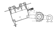
- Patent Document 1 although it is not a vapor phase growth apparatus, when the power transmission mechanism from the motor for moving the X-ray tube, the top plate, the imaging apparatus, etc. to the up and down movement to the ball screw is broken, the apparatus or the like is not dropped.
- a belt breakage detection sensor 114 is provided as an abnormality detection means for detecting an abnormality when the belt 113 is broken.
- the belt breakage detection sensor 114 serving as the abnormality detection means is provided with a transmission type optical sensor including a light emitting unit and a light receiving unit at a position where the belt 113 travels, and detects an abnormality of the power transmission mechanism unit based on the output.
- the ball screw portion has a ball screw mechanism in which the screw rod 115 is fixed to the apparatus and the nut 116 rotates.
- Patent Document 2 as shown in FIG. 13, a structure of a handrail belt driving device for a passenger conveyor is described in which a driving belt for driving a handrail belt is circulated and moved in synchronization with a footboard. Further, as shown in FIG. 14, a biasing mechanism 119 that biases the idler 117 in a direction in which the deflection of the drive chain 118 is eliminated, a shaft body 120 that rotatably supports the idler 117, and the shaft body 120 is indicated by an arrow. A housing 121 configured to be movably supported in the Z direction, and interposed between the housing 121 and the idler 117, the idler 117 is mounted so as to be urged so as to always press the drive chain 118.
- the gas outflow portion 105 itself has a weight of nearly 1 ton and is a heavy object, and it is not possible to hold the supporting ball screw with one, and it is necessary to support with two or more ball screws. was there.
- a position detector 124 that can detect the position of the idler 117 that is moved by being urged by the urging mechanism 119 is provided. Compared with Patent Document 1, prevention of disconnection can be confirmed in a shorter time. .
- the limit switch 123 operates in a state where the length of the drive chain 118 is increased to such an extent that the safety of passengers is jeopardized due to wear or the like, and the operation signal is supplied to the control panel to turn off the motor. Immediately, the movement of the tread plate and the handrail belt can be stopped, and the drive chain 118 is stopped before the entire length becomes longer due to wear and the operation is hindered. It is possible to prevent the customer from becoming in a dangerous state due to the loss of synchronization.
- the drive chain 118 has only one electric motor and drive wheels, and it is difficult to secure a heavy object such as a gas outflow portion while maintaining a certain lifting accuracy.
- the position detector 124 is biased to one location, and when the position detector 124 malfunctions due to some influence, sufficient safety cannot be ensured. Therefore, it is difficult to perform management with a heavy weight in the gas outflow part such as a vapor phase growth apparatus being raised and lowered with high accuracy and sufficiently ensuring safety when the drive chain is bent or disconnected.
- the present invention has been made in view of the above-described conventional problems, and the object thereof is to maintain a high surface height of the gas outflow portion with high accuracy when the gas outflow portion is moved up and down, and which is a heavy gas outflow portion. It is to provide a vapor phase growth apparatus provided with a stop mechanism for preventing the falling of the material.
- a vapor phase growth apparatus is a vapor phase growth apparatus that forcibly stops rotation of a ball screw that moves up and down a gas outflow portion and includes a dropping mechanism for the gas outflow portion.
- a plurality of ball screws are connected to each other, and a plurality of belt breakage detection sensors are installed on all timing belts connecting the respective ball screws and the motor.
- a plurality of ball screws are connected to each other through a shaft to a gas outflow portion, and a belt breakage detection sensor is provided at a part of a timing belt that connects each ball screw and a motor. It is characterized by having installed.
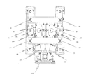
- FIG. 4 is an arrangement top view of the timing belt and the belt breakage detection sensor according to the first embodiment.
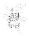
- FIG. 3 is a perspective view of the timing belt and the belt breakage detection sensor according to Embodiment 1 before disconnection.
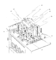
- FIG. 3 is a perspective view of the timing belt and the belt breakage detection sensor according to Embodiment 1 before disconnection.
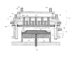
- FIG. 2 is sectional drawing which shows a long chamber structure.
- the growth chamber is provided with a reaction furnace 5 that isolates the interior from the atmosphere side. Inside the reaction furnace 5, a reaction external space 7 and a reaction chamber 8 separated by a reaction chamber partition wall 6 are provided.
- a purge gas supply pipe 9 is connected to the reaction external space 7 and purge gas (N 2 gas, H 2 gas) is introduced.
- the reaction chamber 8 is provided with a substrate holder 11 (susceptor) on which the substrate 10 to be processed is placed.
- the substrate holding unit 11 is provided at one end of the rotation transmitting unit 12 and can be rotated by a rotation mechanism (not shown).
- a substrate heater 13 for heating the substrate to be processed 10 is provided below the substrate holding unit 11.
- a first gas containing a group III element is introduced into the first gas distribution space 15 from the first gas inlet 16a.
- the reaction gas is introduced into the reaction chamber 8 through the plate holes 18a of the central plate 18 communicating with the gas discharge holes H1 of the first gas supply pipe 17b.
- the gas outflow portion 14 has a large number of first gas supply pipes and second gas supply pipes, and has a large area with an increase in the diameter of the substrate to be processed. It has become.
- the gas outflow portion 14 is opened from the reaction furnace 5 by an O-ring 14a connected to an elevating mechanism (not shown), and the replacement and maintenance of the crystal substrate are performed.
- the gas outflow portion 14 of the present embodiment has been described in the embodiment referred to as a shower head, but is not limited to this configuration, and has a gas outflow portion referred to as a central radiation type or a line radiation type. Contains.
- FIG. 3 is a perspective view of the gas outflow portion and the lifting mechanism of the vapor phase growth apparatus.
- the gas outflow part 14 is connected by four shafts 21 penetrating the glove box.
- the four shafts 21 are connected to one ball screw 22 by two each.
- the connected ball screw 22 raises or lowers the connected shaft 21 while rotating at a constant speed.
- the heavy gas outflow portion 14 is configured by four shafts 21 and two ball screws 22, so that the height variation is suppressed with high accuracy and the diameter of the gas outflow portion 14 is increased.
- the brake unit 23 is configured and can be forcibly stopped when the limit of the rise of the ball screw 22 is exceeded.
- FIG. 5 is a top view showing the drive structure of the shaft 21, the ball screw 22, and the timing belt 27 of the motor 26 and the arrangement of the belt breakage detection sensors 28, 29, 30, and 31.
- the two ball screws 22 in FIG. 5 are rotationally driven by a timing belt 27 wound around the ball screw 22 and connected to the same one motor 26 via a relay shaft 32. That is, the driving from the motor 26 is transmitted by the timing belt 27 and converted into rotational driving of the two ball screws 22. At this time, it is assumed that the timing belt 27 is disconnected under the influence of overloading any one of the ball screws 22 or damage to the timing belt 27.
- FIG. 9 is different from FIG. 5 only in the arrangement configuration of the belt breakage detection sensors 28, 29, 30, and 31, and therefore only different portions will be described.
- the present invention can be used for a vapor phase growth apparatus having a lifting mechanism.
- 1 MOCVD apparatus overall, 2 growth chamber, 3 substrate heating mechanism, 4 lifting mechanism, 5 reactor, 6 reaction chamber partition, 7 reaction external space, 8 reaction chamber, 9 purge gas supply pipe, 10 substrate to be processed, 11 substrate holder , 12 Rotation transmission part, 13 Substrate heater, 14 Gas outflow part, 14a O-ring, 15 First gas distribution space, 16 First gas introduction port, 17 Refrigerant space, 17b First gas supply pipe, 18 Central plate, 18a Plate hole, 19 2nd gas distribution space, 19a 2nd gas inlet, 20b 2nd gas supply pipe, 21 shaft, 22 ball screw, 23 brake part, 24 bridge part, 25 connecting part, 26 motor, 27 timing belt, 27a belt, 27b belt, 28 belt breakage detection sensor, 29 belt breakage detection sensor , 30 Belt break detection sensor, 31 Belt break detection sensor, 32 Relay shaft, 33 Light emitting section, 34 Light receiving section, 35 Flag plate, 101 Gas supply source, 102 Reactor, 103 Growth chamber, 104 Gas piping, 105 Gas outflow section , 106 substrate
Landscapes
- Chemical & Material Sciences (AREA)
- General Chemical & Material Sciences (AREA)
- Chemical Kinetics & Catalysis (AREA)
- Engineering & Computer Science (AREA)
- Materials Engineering (AREA)
- Mechanical Engineering (AREA)
- Metallurgy (AREA)
- Organic Chemistry (AREA)
- Chemical Vapour Deposition (AREA)
Abstract
気相成長装置は、ガス流出部(14)を昇降するボールねじ(22)の回転を強制的停止し、ガス流出部(14)の落下機構を備えた気相成長装置であって、ガス流出部(14)にシャフト(21)を介して複数のボールねじ(22)を相互に連結した上、それぞれのボールねじ(22)とモータ(26)とを連結するタイミングベルト(27)の全てに複数のベルト破断検知センサ(28、29、30、31)を設置している。
Description
本発明は、被処理基板上に薄膜を形成する昇降機構を有する気相成長装置に関するものである。
従来、化合物半導体材料を用いる発光ダイオード、半導体レーザ、宇宙用ソーラーパワーデバイス、及び高速デバイスの製造においては、トリメチルガリウム(TMG)又はトリメチルアルミニウム(TMA)等の有機金属ガスと、アンモニア(NH3)、ホスフィン(PH3)又はアルシン(AsH3)等の水素化合物ガスとを成膜に寄与する反応ガスとして成長室に導入して化合物半導体結晶を成長させるMOCVD法が用いられている。
MOCVD法は、上記の反応ガスをキャリアガスと共に成長室内に導入して加熱し、所定の基板上で気相反応させることにより、その基板上に化合物半導体結晶を成長させる方法である。MOCVD法を用いた化合物半導体結晶の製造においては、成長する化合物半導体結晶の品質を向上させながら、コストを抑えて、歩留まりと生産能力とをどのように最大限確保するかということが常に高く要求されている。
図10は、MOCVD法に用いられる従来のガス流出部型気相成長装置の一例の模式的な構成を示す。この気相成長装置においては、ガス供給源101から反応炉102の内部の成長室103に反応ガス及びキャリアガスを導入するためのガス配管104が接続されており、反応炉102における内部の成長室103の上部には該成長室103に反応ガス及びキャリアガスを導入するための複数のガス吐出孔を配設したガス流出部105がガス導入部として設置されている。
また、成長室103の下部には、基板106を載置するためのサセプタ107が、ガス流出部105と対向するように設置されている。サセプタ107は、基板106を加熱するためのヒータ108を備え、図示しないアクチュエータによって回転軸109を中心に回転自在となっている。
さらに、反応炉102の下部には、成長室103内のガスを外部に排気するためのガス排気部110が設置されている。このガス排気部110は、パージライン111を介して、排気されたガスを無害化するための排ガス処理装置112に接続されている。
上記構成のガス流出部型気相成長装置において、化合物半導体結晶を成長させる場合には、まず、サセプタ107に基板106を設置し、サセプタ107を回転させ、ヒータ108により基板106を所定の温度に加熱する。その後、ガス流出部105に配設されている複数のガス吐出孔から成長室103に反応ガス及びキャリアガス(不活性ガス)を導入し、一定時間保持する事で、基板上106上に化合物半導体の結晶成長を行う。そして、反応炉102上部のガス流出部105を上昇させて、成長した基板の交換や反応分解物の除去を実施した後、再度、反応炉102上部のガス流出部105を下降させて成長室103を気密にした上で、同様の作業を繰り返し行う。
一方、反応炉102上部のガス流出部105は、図示しない昇降機構によって保持されている。ガス流出部105は、基板106の大径化に伴い、重量が1トン近くになり、近年、ガス流出部105を保持する昇降機構に加わる重量がかなり増加している。その為、結晶成長毎に実施されるガス流出部105の昇降動作時にガス流出部105が落下しない対策を十分に実施することが必要となっている。このような昇降機構の安全に対処するための方法が特開2002-11003号公報(特許文献1)および特開2007-191284号公報(特許文献2)でそれぞれ提案されている。
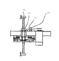
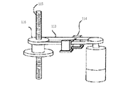
特許文献1においては、気相成長装置ではないものの、X線管、天板、撮像装置等を昇降移動させるためのモータからボールネジへの動力伝達機構が破断した場合、装置等が落下しないように安全な機構を備えたX線診断装置の構造が記載されている。図11に示すように、そのベルト113が破断した時、異常を検知する異常検知手段としてのベルト破断検出用センサ114を備えている。異常検出手段としてのベルト破断検出用センサ114は、例えば、ベルト113の走行する位置に、光発光部と受光部からなる透過型光センサを設けてその出力により動力伝達機構部の異常を検出する。一方、ボールネジ部は、ネジ棒115が装置に固定され、ナット116が回転するボールネジ機構を有している。
特許文献2においては、図13に示すように、手摺ベルトを駆動する駆動ベルトが、踏み板と同期して循環移動するように駆動する乗客コンベアの手摺ベルト駆動装置の構造が記載されている。また、図14に示すように、アイドラー117を駆動チェーン118のたわみが解消する方向に付勢する付勢機構119は、アイドラー117を回転自在に支持する軸体120と、その軸体120を矢印Z方向に移動可能に支持するように構成された筐体121と、その筐体121とアイドラー117との間に介装され、アイドラー117を常に駆動チェーン118を押圧するように付勢可能に装着されたコイルばね122とで構成されている。駆動チェーン118が摩耗等により、乗客の安全性が危ぶまれる程度に長さが長くなった状態では、リミットスイッチ123が作動し、その作動信号が制御盤に供給されて電動機をOFF操作させ、直ちに、踏み板及び手摺ベルトの移動を停止させることができる構造となっている。
気相成長装置の課題として、結晶成長毎に実施されるガス流出部105の昇降時にガス流出部105が落下しないように安全面で対策を実施することが必要であった。
さらに、ガス流出部105自体の重量が1トン近く、かなりの重量物となっており、支持するボールねじを1本で保持する事が出来ず、2本以上の複数のボールねじで支持する必要があった。
また、2本以上の複数のボールねじは、内部の成長室103に反応ガス及びキャリアガスを導入するためのガス配管104がガス流出部105に接続されている関係上、常に一定のガス流出部105の表面高さを維持しながら、昇降機構を動作させなければ、ガスの流量や流速に悪影響を及ぼし、さらには結晶成長させる際の成膜不均一を発生させる可能性があった。
特許文献1の場合は、ベルト113の走行する位置に、光発光部と受光部からなる透過型光センサを設けてその出力により動力伝達機構部の異常を検出する。ボールネジ部は、ネジ棒115が装置に固定され、ナット116が回転するボールネジ機構である。この機構のネジ棒115は1本であり、昇降させるワーク(X線管、撮像装置、天板等が取り付けられている)には、重量物である構造体を連結する事は出来ない。また、図12に示すように、透過型光センサ114では、ベルトが断線して、遮光する部分が完全にセンサ前面から無くならないと感知する事はなく、センサの反応までに時間的な遅れが発生する。特に、透過型光センサ間の2本のベルトの内、1本のみが断線した場合でも、残りの1本で遮光された状態が維持している場合、ベルト断線の検知が困難である。その為、気相成長装置のような大型の装置で求められる落下するまでの短時間での落下防止を十分に確保する事が出来ない。
特許文献2の場合は、付勢機構119により付勢されて移動するアイドラー117の位置を検出可能な位置検出器124を備えており、特許文献1に比べて、短時間で断線防止を確認出来る。また、駆動チェーン118が摩耗等により、乗客の安全性が危ぶまれる程度に長さが長くなった状態で、リミットスイッチ123が作動し、その作動信号が制御盤に供給されて電動機をOFF操作させ、直ちに、踏み板及び手摺ベルトの移動を停止させることができ、駆動チェーン118が摩耗により全体の長さが長くなって、運転に支障が生ずる前に停止させることで、駆動ベルトが踏み板との間の同期がはずれ等により利用客が危険な状態になるのを未然に防止できる働きがある。
しかし、駆動チェーン118は、1つの電動機、駆動輪のみを有しており、ガス流出部のような重量物を一定の昇降精度を維持しながら確保するのは困難である。また、位置検出器124は1カ所に付勢されており、何らかの影響で位置検出器124が動作不具合時には、十分な安全性を確保出来ない。従って、気相成長装置のようなガス流出部の重量物を精度良く昇降させ、かつ駆動チェーンのたわみ、断線時での安全性を十分確保した上での管理が困難であった。
本発明は、上記従来の問題点に鑑みなされたものであって、その目的は、ガス流出部の昇降時に、精度良くガス流出部の表面高さを維持しつつ、重量物であるガス流出部の落下を防止する停止機構を備えた気相成長装置を提供する事である。
本発明の気相成長装置は、ガス流出部を昇降するボールねじの回転を強制的停止し、ガス流出部の落下機構を備えた気相成長装置であって、ガス流出部にシャフトを介して複数のボールねじを相互に連結した上、それぞれのボールねじとモータとを連結するタイミングベルトの全てに複数のベルト破断検知センサを設置したことを特徴とする。
または、本発明の気相成長装置は、ガス流出部にシャフトを介して複数のボールねじを相互に連結した上、それぞれのボールねじとモータとを連結するタイミングベルトの一部にベルト破断検知センサを設置したことを特徴とする。
気相成長装置のガス流出部に複数のシャフトを相互に連結した上、それぞれのシャフトとボールねじとモータを連結するタイミングベルトに複数のベルト破断検知センサを設置する事で、ガス流出部の昇降時に、精度良くガス流出部の表面高さを維持しつつ、重量物であるガス流出部の落下を防止する事が可能となる。
(実施の形態1)
本発明の一実施形態について図1に基づいて説明すれば、以下の通りである。なお、本発明の図面において、同一の参照符号は、同一部分又は相当部分を表わすものとする。
本発明の一実施形態について図1に基づいて説明すれば、以下の通りである。なお、本発明の図面において、同一の参照符号は、同一部分又は相当部分を表わすものとする。
図1に、本発明の気相成長装置として、MOCVD装置全体1の模式的な構成の一例を示す。図1に示すように、MOCVD装置全体1は、主に化合物半導体結晶を成長させる成長室2、成長室内の基板を加熱する基板加熱機構3、ガス流出部を昇降する昇降機構4、図示しないガス流出部周辺を冷却する冷却配管系、成長室の排気を行う高真空排気系、プロセスガス排気系から構成される。本発明は、これらの主構成のうち、ガス流出部を昇降する昇降機構に関する。
また、図2は、長室内構成を示す断面図である。成長室は、内部を大気側と隔離する反応炉5を備えており、反応炉5内部には、反応室隔壁6によって分離された反応外部空間7と反応室8が設けられている。反応外部空間7には、パージガス供給管9が接続されており、パージガス(N2ガス、H2ガス)が導入されている。反応室8には、被処理基板10を載置する基板保持部11(サセプタ)が備えられている。基板保持部11は、回転伝達部12の一端に備え付けられており、図示しない回転機構により回転可能となっている。また、基板保持部11の下側には、被処理基板10を加熱するための基板加熱ヒータ13が設けられている。
反応炉5の上部には、ガス流出部14が取外し可能に配設されている。反応炉5とガス流出部14は、Oリング14aでシールされており、反応炉5の内部をガス排出口から排気して気密状態に維持できるようなっている。
被処理基板10に化合物半導体結晶を成膜するときは、第1ガス分配空間15に、例えば、III族の元素を含む第1ガスが、第1ガス導入口16aから導入され、冷媒空間17を貫通する複数の第1ガス供給管17bを通って冷却された後、第1ガス供給管17bのガス吐出孔H1に連通する中央プレート18のプレート孔18aから反応室8に導入される。
また、第2ガス分配空間19には、例えば、V族の元素を含む第2ガスが、第2ガス導入口19aから導入され、冷媒空間17を貫通する複数の第2ガス供給管20bを通って冷却された後、第2ガス供給管20bのガス吐出孔H2に連通する中央プレート18から反応室8に導入される。
このように、ガス流出部14は、多数の第1ガス供給管、第2ガス供給管を有し、かつ被処理基板の大径化と共に面積が大型になっており、1トン近くの重量物となっている。成膜後には、ガス流出部14は、反応炉5からOリング14aで図示しない昇降機構に連結して開放され、結晶基板の交換及びメンテナンスが実施される。本実施例のガス流出部14は、シャワーヘッドといわれる実施例で説明したが、本構成に限定されるものではなく、中央放射型、ライン放射型といわれるガス流出部を有しているものを含んでいる。
次に、本発明の特徴的である昇降機構の実施例を図3から図4を用いて、ベルト破断検知センサ及び別の実施例を図5から図7を用いて詳細に説明する。
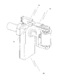
図3に気相成長装置のガス流出部及び昇降機構の斜視図を示す。ガス流出部14は、グローブボックスを貫通した4本のシャフト21にて連結している。4本のシャフト21は互いに2本ずつ1本のボールねじ22と連結している。連結しているボールねじ22は、一定の速度で回転しながら、連結しているシャフト21を上昇、あるいは下降させる。その結果、シャフト21に連結したガス流出部14が上昇、あるいは下降を一定の速度で行う。重量物であるガス流出部14は、4本のシャフト21及び2本のボールねじ22にて構成される事で、高さばらつきを抑えて精度良く、大径化したガス流出部14の上部にブレーキ部23を構成し、ボールねじ22の上昇の限界を超えた場合に強制的に静止出来る。さらに、2本のボールねじ22は、それぞれ上部において橋渡し部24を介して連結しており、ガス流出部によるボールねじへの負荷を均一に分散する効果を有している。図3では、ボールねじ22と4本のシャフト21の連結部分25は下部に位置しており、ガス流出部14が下降した状態を表している。
図4は、気相成長装置のガス流出部上部の昇降機構の斜視図である。図4では、図3に比べて連結部分25が上部に位置しており、図に記載した矢印方向にボールねじ22の回転によって4本のシャフト21が上昇し、ガス流出部14が上昇した状態を表している。2本のボールねじ22は、それぞれ上部において橋渡し部24を介して連結により、ガス流出部14によるボールねじ22への負荷を均一に分散しながら上昇し、上限にて強制的に静止している状態になっている。これらの構造により、4本のシャフト21の落下への安全性が連結されていない場合に比べて改善されている。
図5にシャフト21、ボールねじ22、モータ26のタイミングベルト27による駆動構造及びベルト破断検知センサ28、29、30、31の配置を上面図で示す。図5における2本のボールねじ22の回転駆動は、ボールねじ22に巻かれたタイミングベルト27によって、中継軸32を介して、それぞれ同じ1つのモータ26に連結されている。つまり、このモータ26からの駆動をタイミングベルト27が伝達し、各2本のボールねじ22の回転駆動へと変換する構造となっている。この時、いずれかのボールねじ22への過加重、あるいはタイミングベルト27の損傷の影響を受けて、タイミングベルト27が断線する事が想定される。そこで、モータ26と中継軸32を繋ぐ2本のタイミングベルト27にそれぞれ2カ所のベルト破断検知センサ28、31を配置し、中継軸32とボールねじ22を繋ぐ2本のタイミングベルト27の2カ所のベルト破断検知センサ29、30を配置し、各ベルト破断検知センサ28、29、30、31は、図5のようにモータ26を中心に左右ボールねじ22に対照な位置に配置されている。この構成を有する事で、いずれかのボールねじ22への過加重、あるいはタイミングベルト27の損傷の影響を受けて、タイミングベルト27が断線する場合に、いずれかのベルト破断検知センサ28、29、30、31がその状況を検知し、断線によるガス流出部14の落下を防止できる。また、複数のベルト位置のいずれにおいてもベルト破断検知センサ28、29、30、31を配置する事で、いずれもタイミングベルト27の破断時にも短時間に落下を防止出来る効果を有する。
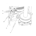
図6に一例として、ベルト破断検知センサ28の構造図を示す。ベルト破断検知センサ28は、主に発光部33と受光部34からなるフォトセンサとフラグ板35で構成される。さらに、図7において、ベルト破断検知センサの断線時の挙動について説明する。これらのベルト破断検知センサを使用し、図7のように、タイミングベルト27が断線していない状況では、タイミングベルト27によるテンションでフラグ板35が押され、発光部33と受光部34との間にフラグ板35が挿入した状態で受光部34には入光せず、ブレーキが常時通電となる。次に、図8のように、タイミングベルト27が断線した状況では、タイミングベルト27によるテンションが瞬時に失われ、フォトセンサにおけるフラグ板35の発光部33と受光部34との間の遮光が無くなり、受光部34に入光する。この状態ではブレーキは遮電されて、ガス流出部14の落下を防止する停止機構が瞬時に作動する。
(実施の形態2)
別の実施形態について図9に基づいて説明する。図9は、図5でベルト破断検知センサ28、29、30、31の配置構成のみが異なるため、異なる部分のみ説明する。
別の実施形態について図9に基づいて説明する。図9は、図5でベルト破断検知センサ28、29、30、31の配置構成のみが異なるため、異なる部分のみ説明する。
図9において、ベルト破断検知センサ30、31の配置状態を示す。本実施例では、モータ26と中継軸32を繋ぐ2本のタイミングベルト27のうち1カ所にベルト破断検知センサ31を配置し、中継軸32とボールねじ22を繋ぐ2本のタイミングベルト27のうち1カ所にベルト破断検知センサ30を配置している。
この構成により、ベルト破断検知センサの個数を削減でき、タイミングベルト27の破断時に、実施例1に対して検知時間は遅くなるが、より低コストで断線によるガス流出部14の落下防止を検知できる。また、ベルト破断検知センサ30、31は、タイミングベルト27の長さ方向に対して、垂直方向にフラグ板35が動作するように、グローボックス上に固定されている。
図9のように、タイミングベルト27のベルト27a、27bの方向位置が異なる場合、それぞれの方向位置に垂直な方向にフラグ板35が動作するように、ベルト破断検知センサ30、31の配置位置を変更している。
また、これらのベルトへの加重、たわみの一例の数値としては、ベルト27aでは36.5N、たわみ8.4mm程度、ベルト27bでは35.2N、たわみ3.3mm程度を最適な条件で設定されている。
今回開示された実施例はすべての点で例示であって制限的なものではないと考えられるべきである。本発明の範囲は上記した説明ではなくて請求の範囲によって示され、請求の範囲と均等の意味及び範囲内でのすべての変更が含まれることが意図される。
本発明は、昇降機構を有する気相成長装置に利用することができる。
1 MOCVD装置全体、2 成長室、3 基板加熱機構、4 昇降機構、5 反応炉、6 反応室隔壁、7 反応外部空間、8 反応室、9 パージガス供給管、10 被処理基板、11 基板保持部、12 回転伝達部、13 基板加熱ヒータ、14 ガス流出部、14a Oリング、15 第1ガス分配空間、16 第1ガス導入口、17 冷媒空間、17b 第1ガス供給管、18 中央プレート、18a プレート孔、19 第2ガス分配空間、19a 第2ガス導入口、20b 第2ガス供給管、21 シャフト、22 ボールねじ、23 ブレーキ部、24 橋渡し部、25 連結部分、26 モータ、27 タイミングベルト、27a ベルト、27b ベルト、28 ベルト破断検知センサ、29 ベルト破断検知センサ、30 ベルト破断検知センサ、31 ベルト破断検知センサ、32 中継軸、33 発光部、34 受光部、35 フラグ板、101 ガス供給源、102 反応炉、103 成長室、104 ガス配管、105 ガス流出部、106 基板、107 サセプタ、108 ヒータ、109 回転軸、110 ガス排気部、111 パージライン、112 排ガス処理装置、113 ベルト、114 透過型光センサ、115 ネジ棒、116 ナット、117 アイドラー、118 駆動チェーン、119 付勢機構、120 軸体、121 筐体、122 コイルばね、123 リミットスイッチ、124 位置検出器。
Claims (6)
- ガス流出部(14)と、複数のボールねじ部と、前記ボールねじ部に連結したガス流出部を昇降するシャフト部と、前記ボールねじ部とモータ部の間にタイミングベルト(27)による保持機構と、前記タイミングベルトの近傍にセンサ部とを備えた気相成長装置。
- 前記ボールねじ部とモータ部の間に中継軸(32)を有し、前記ボールねじ部と前記中継軸及び前記中継軸と前記モータ部間の全てのタイミングベルト近傍にセンサ部を備えた請求項1に記載の気相成長装置。
- 前記ボールねじ部とモータ部の間に中継軸(32)を有し、前記ボールねじ部と前記中継軸及び前記中継軸と前記モータ部間のいずれか一方のタイミングベルト近傍にセンサ部を備えた請求項1に記載の気相成長装置。
- 前記ガス流出部は、複数のガス配管からなるシャワーヘッド部を構成する請求項1に記載の気相成長装置。
- 前記ボールねじ部に、ガス流出部の上昇を停止するブレーキ部(23)を備えたことする請求項1に記載の気相成長装置。
- 前記ボールねじ部は、橋渡し部(24)を介して互いに連結されている請求項1に記載の気相成長装置。
Applications Claiming Priority (2)
| Application Number | Priority Date | Filing Date | Title |
|---|---|---|---|
| JP2011049090A JP5048853B2 (ja) | 2011-03-07 | 2011-03-07 | 昇降機構を有する気相成長装置 |
| JP2011-049090 | 2011-03-07 |
Publications (1)
| Publication Number | Publication Date |
|---|---|
| WO2012120970A1 true WO2012120970A1 (ja) | 2012-09-13 |
Family
ID=46797940
Family Applications (1)
| Application Number | Title | Priority Date | Filing Date |
|---|---|---|---|
| PCT/JP2012/053118 Ceased WO2012120970A1 (ja) | 2011-03-07 | 2012-02-10 | 昇降機構を有する気相成長装置 |
Country Status (2)
| Country | Link |
|---|---|
| JP (1) | JP5048853B2 (ja) |
| WO (1) | WO2012120970A1 (ja) |
Cited By (1)
| Publication number | Priority date | Publication date | Assignee | Title |
|---|---|---|---|---|
| US9227479B2 (en) | 2011-03-15 | 2016-01-05 | Jaguar Land Rover Limited | Wading vehicle control system |
Families Citing this family (1)
| Publication number | Priority date | Publication date | Assignee | Title |
|---|---|---|---|---|
| JP7122907B2 (ja) * | 2018-08-24 | 2022-08-22 | 東京エレクトロン株式会社 | 昇降装置、半導体製造装置の組立装置、半導体製造装置の組立方法 |
Citations (3)
| Publication number | Priority date | Publication date | Assignee | Title |
|---|---|---|---|---|
| JP2002184761A (ja) * | 2000-12-15 | 2002-06-28 | Tokyo Electron Ltd | プラズマ処理装置、プラズマ処理装置の組付け解体方法及びその専用治具 |
| JP2004311887A (ja) * | 2003-04-10 | 2004-11-04 | Sumitomo Heavy Ind Ltd | 基板処理装置及びそのメンテナンス方法 |
| JP2011192912A (ja) * | 2010-03-16 | 2011-09-29 | Tokyo Electron Ltd | プラズマ処理装置 |
-
2011
- 2011-03-07 JP JP2011049090A patent/JP5048853B2/ja not_active Expired - Fee Related
-
2012
- 2012-02-10 WO PCT/JP2012/053118 patent/WO2012120970A1/ja not_active Ceased
Patent Citations (3)
| Publication number | Priority date | Publication date | Assignee | Title |
|---|---|---|---|---|
| JP2002184761A (ja) * | 2000-12-15 | 2002-06-28 | Tokyo Electron Ltd | プラズマ処理装置、プラズマ処理装置の組付け解体方法及びその専用治具 |
| JP2004311887A (ja) * | 2003-04-10 | 2004-11-04 | Sumitomo Heavy Ind Ltd | 基板処理装置及びそのメンテナンス方法 |
| JP2011192912A (ja) * | 2010-03-16 | 2011-09-29 | Tokyo Electron Ltd | プラズマ処理装置 |
Cited By (1)
| Publication number | Priority date | Publication date | Assignee | Title |
|---|---|---|---|---|
| US9227479B2 (en) | 2011-03-15 | 2016-01-05 | Jaguar Land Rover Limited | Wading vehicle control system |
Also Published As
| Publication number | Publication date |
|---|---|
| JP2012186355A (ja) | 2012-09-27 |
| JP5048853B2 (ja) | 2012-10-17 |
Similar Documents
| Publication | Publication Date | Title |
|---|---|---|
| CN100568449C (zh) | 立式热处理装置及立式热处理装置中移载机构的控制方法 | |
| US7905700B2 (en) | Vertical-type heat processing apparatus and method of controlling transfer mechanism in vertical-type heat processing apparatus | |
| CN102653883B (zh) | 衬底处理装置及衬底的制造方法 | |
| KR101885434B1 (ko) | 구동 모듈 및 이를 포함하는 타워 리프트 | |
| US10766056B2 (en) | Purge device, purge stocker, and method for feeding purge gas | |
| CN102154623B (zh) | 用于气相沉积系统中基板检测的主动观察端口检测组件 | |
| US20180135166A1 (en) | Epitaxial growth device, production method for epitaxial wafer, and lift pin for epitaxial growth device | |
| WO2012096466A2 (ko) | 박막 증착 장치 및 이를 포함한 기판 처리 시스템 | |
| JP2012049342A (ja) | 基板処理装置および基板処理方法 | |
| WO2011105370A1 (ja) | 半導体装置の製造方法及び基板製造方法及び基板処理装置 | |
| KR102552110B1 (ko) | 처리 장치 | |
| JP5048853B2 (ja) | 昇降機構を有する気相成長装置 | |
| WO2006038584A1 (ja) | 半導体製造装置及び半導体装置の製造方法 | |
| KR20180126828A (ko) | 타워 리프트 | |
| KR20180069389A (ko) | 타워 리프트 | |
| WO2016017685A1 (ja) | 基板処理装置、基板搬送方法及び半導体装置の製造方法並びに記録媒体 | |
| CN102267073B (zh) | 桥式晶体材料双头磨床 | |
| KR20160043486A (ko) | 유기금속화학기상증착장치 | |
| CN114256048B (zh) | 一种等离子体反应装置、方法及机械臂 | |
| JP2013051374A (ja) | 基板処理装置 | |
| US20230307255A1 (en) | Systems and methods for controlling accretion in semiconductor processing system exhaust arrangements | |
| CN220148355U (zh) | 一种传送机构及移载机器人 | |
| KR20140017088A (ko) | 셔틀 및 그를 가지는 기판처리장치 | |
| JP2013045884A (ja) | 基板処理装置 | |
| JP2010074073A (ja) | 基板処理装置 |
Legal Events
| Date | Code | Title | Description |
|---|---|---|---|
| 121 | Ep: the epo has been informed by wipo that ep was designated in this application |
Ref document number: 12755768 Country of ref document: EP Kind code of ref document: A1 |
|
| NENP | Non-entry into the national phase |
Ref country code: DE |
|
| 122 | Ep: pct application non-entry in european phase |
Ref document number: 12755768 Country of ref document: EP Kind code of ref document: A1 |