WO2012120875A1 - 変倍光学系および撮像装置 - Google Patents
変倍光学系および撮像装置 Download PDFInfo
- Publication number
- WO2012120875A1 WO2012120875A1 PCT/JP2012/001519 JP2012001519W WO2012120875A1 WO 2012120875 A1 WO2012120875 A1 WO 2012120875A1 JP 2012001519 W JP2012001519 W JP 2012001519W WO 2012120875 A1 WO2012120875 A1 WO 2012120875A1
- Authority
- WO
- WIPO (PCT)
- Prior art keywords
- lens
- lens group
- positive
- optical system
- focal length
- Prior art date
- Legal status (The legal status is an assumption and is not a legal conclusion. Google has not performed a legal analysis and makes no representation as to the accuracy of the status listed.)
- Ceased
Links
Images


Classifications
-
- G—PHYSICS
- G02—OPTICS
- G02B—OPTICAL ELEMENTS, SYSTEMS OR APPARATUS
- G02B15/00—Optical objectives with means for varying the magnification
- G02B15/14—Optical objectives with means for varying the magnification by axial movement of one or more lenses or groups of lenses relative to the image plane for continuously varying the equivalent focal length of the objective
- G02B15/144—Optical objectives with means for varying the magnification by axial movement of one or more lenses or groups of lenses relative to the image plane for continuously varying the equivalent focal length of the objective having four groups only
- G02B15/1441—Optical objectives with means for varying the magnification by axial movement of one or more lenses or groups of lenses relative to the image plane for continuously varying the equivalent focal length of the objective having four groups only the first group being positive
- G02B15/144113—Optical objectives with means for varying the magnification by axial movement of one or more lenses or groups of lenses relative to the image plane for continuously varying the equivalent focal length of the objective having four groups only the first group being positive arranged +-++
-
- G—PHYSICS
- G02—OPTICS
- G02B—OPTICAL ELEMENTS, SYSTEMS OR APPARATUS
- G02B15/00—Optical objectives with means for varying the magnification
- G02B15/14—Optical objectives with means for varying the magnification by axial movement of one or more lenses or groups of lenses relative to the image plane for continuously varying the equivalent focal length of the objective
-
- G—PHYSICS
- G02—OPTICS
- G02B—OPTICAL ELEMENTS, SYSTEMS OR APPARATUS
- G02B3/00—Simple or compound lenses
- G02B3/02—Simple or compound lenses with non-spherical faces
- G02B3/04—Simple or compound lenses with non-spherical faces with continuous faces that are rotationally symmetrical but deviate from a true sphere, e.g. so called "aspheric" lenses
Definitions
- the present invention relates to a variable magnification optical system and an imaging apparatus used for a video camera, an electronic still camera, and the like, and is particularly suitable for use as a surveillance camera and can be used in both the visible range and the near infrared range, and the variable magnification optical system.
- the present invention relates to an image pickup apparatus including a double optical system.
- CCTV Closed-circuit
- imaging devices such as video cameras, electronic still cameras, and surveillance cameras that use an imaging device such as a CCD (Charge-Coupled Device) or CMOS (Complementary Metal-Oxide Semiconductor) as a recording medium.
- CCD Charge-Coupled Device
- CMOS Complementary Metal-Oxide Semiconductor
- Variable Television has been developed.
- a variable magnification optical system for CCTV a four-group configuration has many advantages such as simplicity and ease of handling of the lens barrel / magnification mechanism, and many have been proposed.
- Patent Documents 1 and 2 listed below in order from the object side, one lens unit having a positive refractive power and fixed at the time of zooming and a negative refractive power and moving in the optical axis direction at the time of zooming
- the second lens group, the stop fixed at the time of zooming, the third lens group having positive refractive power and fixed at the time of zooming, and the positive refractive power, and the optical axis direction at the time of zooming A zoom lens having a four-group configuration in which a fourth lens group that moves to the center and performs a focusing action is arranged is described.
- the present invention has been made in view of the above circumstances, and while being small and inexpensive, the F value is small, chromatic aberration is well corrected in a wide wavelength range from the visible range to the near infrared range, and high optical performance is achieved. It is an object of the present invention to provide a variable magnification optical system and an image pickup apparatus including the variable magnification optical system.
- the variable magnification optical system of the present invention includes, in order from the object side, a first lens group having a positive refractive power, a second lens group having a negative refractive power, a stop, and a third lens having a positive refractive power. And a fourth lens group having a positive refractive power.
- the first lens group, the stop, and the third lens group are fixed with respect to the image plane.
- a variable power optical system configured such that the lens group moves in the optical axis direction and the fourth lens group has a focusing function, and the third lens group has at least one aspheric surface,
- the lens includes a positive lens and a cemented lens obtained by bonding a positive lens and a biconcave lens, and satisfies the following conditional expressions (1) to (4).
- f3 focal length of the third lens group
- fw focal length of the entire system at the wide angle end
- f31p focal length of the positive lens closest to the object side in the third lens group
- f3C focal length ⁇ 3Cn of the cemented lens of the third lens group
- Abbe number ⁇ 3Cp for the d-line of the biconcave lens constituting the cemented lens of the third lens group Abbe number for the d-line of the positive lens constituting the cemented lens of the third lens group
- the biconcave lens of the third lens group is configured so that the absolute value of the radius of curvature of the image side surface is larger than the object side.
- the second lens group of the variable magnification optical system of the present invention includes, in order from the object side, a negative lens, a positive meniscus lens having a concave surface facing the object side, a biconcave lens, and a positive lens. ) To (7) are preferably satisfied.
- f2 focal length ⁇ 2p of second lens group: Abbe number dz2 with respect to d-line of positive meniscus lens of second lens group: movement amount of second lens group in optical axis direction when zooming from wide angle end to telephoto end
- the sign of dz2 is positive when moving to the image side.
- the first lens unit of the variable magnification optical system includes, in order from the object side, a negative lens having a concave surface directed to the image side and three positive lenses having a concave surface directed to the image side. It is preferable to satisfy 8) to (10). 1.0 ⁇
- the fourth lens group of the variable magnification optical system includes, in order from the object side, a biconvex lens, a negative meniscus lens having a concave surface facing the image side, and a positive lens.
- the following conditional expressions (11), (12 ) Is preferably satisfied.
- f4pF focal length of the biconvex lens of the fourth lens group
- f4pR focal length of the positive lens closest to the image side in the fourth lens group
- f4n focal length of the negative meniscus lens of the fourth lens group
- f4 focal length of the fourth lens group
- the surface shape of the lens and the sign of refractive power in the variable magnification optical system according to the present invention are considered in the paraxial region when an aspheric surface is included.
- the number of lenses in the variable magnification optical system of the present invention is the number of lenses as constituent elements. For example, when there is a cemented lens in which a plurality of single lenses of different materials are cemented, the number of single lenses constituting the cemented lens is counted.
- the imaging apparatus of the present invention is characterized by including the above-described variable magnification optical system of the present invention.
- the zoom optical system of the present invention includes, in order from the object side, a positive first lens group, a negative second lens group, a stop, a positive third lens group, and a positive fourth lens group.
- the first lens group, the stop, and the third lens group are fixed with respect to the image plane
- the second lens group G2 and the fourth lens group G4 move in the optical axis direction
- the fourth lens group G4 In the lens system having a focusing function, the lens configuration of the third lens group is suitably set so as to satisfy the conditional expressions (1) to (4) at the same time.
- good chromatic aberration correction and high optical performance in a wide wavelength range from the visible range to the near infrared range can be realized.
- the imaging apparatus of the present invention includes the variable magnification optical system of the present invention, it can be configured to be small and inexpensive, can be photographed at low illuminance, and has a wide wavelength range from the visible range to the near infrared range. Therefore, a good image can be obtained.
- Sectional drawing which shows the lens structure in the telephoto end of the variable magnification optical system concerning one Embodiment of this invention are cross-sectional views showing lens configurations at the wide-angle end, intermediate focal length state, and telephoto end of the variable magnification optical system according to Example 1 of the present invention, respectively.
- 3A to 3C are cross-sectional views showing lens configurations at the wide-angle end, the intermediate focal length state, and the telephoto end of the variable magnification optical system according to Example 2 of the present invention, respectively.
- FIGS. 4A to 4C are cross-sectional views showing lens configurations at the wide-angle end, the intermediate focal length state, and the telephoto end of the variable magnification optical system according to Example 3 of the present invention, respectively.
- FIGS. 5A to 5C are sectional views showing lens configurations at the wide-angle end, the intermediate focal length state, and the telephoto end of the variable magnification optical system according to Example 4 of the present invention, respectively.
- FIGS. 6A to 6C are sectional views showing lens configurations at the wide-angle end, the intermediate focal length state, and the telephoto end of the variable magnification optical system according to Example 5 of the present invention, respectively.
- FIGS. 7A to 7C are cross-sectional views showing lens configurations at the wide-angle end, intermediate focal length state, and telephoto end of the variable magnification optical system according to Example 6 of the present invention, respectively.
- FIGS. 8A to 8C are sectional views showing lens configurations at the wide-angle end, the intermediate focal length state, and the telephoto end of the variable magnification optical system according to Example 7 of the present invention, respectively.
- FIGS. 9A to 9C are sectional views showing lens configurations at the wide-angle end, the intermediate focal length state, and the telephoto end of the variable magnification optical system according to the eighth embodiment of the present invention, respectively.
- FIGS. 10A to 10C are cross-sectional views showing lens configurations at the wide-angle end, the intermediate focal length state, and the telephoto end of the variable magnification optical system according to Example 9 of the present invention, respectively.
- 11A to 11I are diagrams showing aberrations of the variable magnification optical system according to Example 1 of the present invention.
- FIGS. 12A to 12I are diagrams showing aberrations of the variable magnification optical system according to Example 2 of the present invention.
- FIGS. 13A to 13I are diagrams showing aberrations of the variable magnification optical system according to Example 3 of the present invention.
- FIGS. 14A to 14I are diagrams showing aberrations of the variable magnification optical system according to Example 4 of the present invention.
- FIGS. 15A to 15I are diagrams showing aberrations of the variable magnification optical system according to Example 5 of the present invention.
- FIGS. 16A to 16I are diagrams showing aberrations of the variable magnification optical system according to Example 6 of the present invention.
- 17A to 17I are diagrams showing aberrations of the variable magnification optical system according to Example 7 of the present invention.
- FIGS. 18A to 18I are graphs showing aberrations of the variable magnification optical system according to Example 8 of the present invention.
- FIGS. 19A to 19I are diagrams showing aberrations of the variable magnification optical system according to Example 9 of the present invention.
- 1 is a schematic configuration diagram of an imaging apparatus according to an embodiment of the present invention.
- 1A and 1B are cross-sectional views showing a configuration example of a variable magnification optical system according to an embodiment of the present invention.
- 1A and 1B show lens arrangements at the wide-angle end and the telephoto end, respectively, in a state in which an object at infinity is in focus, and corresponds to a variable power optical system of Example 1 described later.
- 1A and 1B the left side is the object side and the right side is the image side
- the cross-sectional views of FIGS. 1A and 1B show the axial light beams 2A and 2B, the off-axis light beam 3A at the maximum field angle, 3B is also shown.
- the variable magnification optical system includes, in order from the object side along the optical axis Z, a first lens group G1 having a positive refractive power, a second lens group G2 having a negative refractive power, an aperture stop St, A third lens group G3 having a positive refractive power and a fourth lens group G4 having a positive refractive power are provided.
- the aperture stop St shown in FIG. 1 does not necessarily indicate the size or shape, but indicates the position on the optical axis Z.
- FIG. 1 shows an example in which a parallel plate-shaped optical member PP that assumes these is arranged between the fourth lens group G4 and the image plane Sim.
- variable magnification optical system at the time of variable magnification, the first lens group G1, the aperture stop St, and the third lens group G3 are fixed with respect to the image plane Sim, and the second lens group G2 and the fourth lens group G4. Is configured to move in the optical axis direction.
- the second lens group G2 has a zooming function
- the fourth lens group G4 is configured to have a focusing function when the object distance varies or when zooming.
- the above four-group configuration relating to the zooming optical system is a zoom lens or varifocal lens having a zooming ratio of the 10x class, and has many advantages such as simplicity of the lens barrel and zooming mechanism and easy handling.
- This variable power optical system aims to achieve a small F value and high optical performance while being small and inexpensive, and in particular, from the visible range to the near infrared range in the entire zoom range from the wide-angle end to the telephoto end.
- the objective is to realize good chromatic aberration correction in a wide wavelength range up to.
- the lens configuration of the third lens group G3. This is because the third lens group G has the highest axial light beam height on the wide-angle side in the entire system, and the aperture stop St is disposed immediately before the object side. This is because the lens group has a low height and is therefore less affected by off-axis aberrations and can easily correct axial chromatic aberration.
- achromaticity with the near-infrared region uses a material with a large Abbe number for the negative lens and a material with a larger Abbe number for the positive lens.
- the axial chromatic aberration between the near-infrared region and the visible region on the wide-angle side can be minimized as much as possible.
- the first lens group G1 is a lens group that has the highest axial light beam height on the telephoto side, and therefore has a strong influence on the axial chromatic aberration, so the configuration of the first lens group G1 is optimized. This is advantageous for chromatic aberration correction on the telephoto side. It is preferable to use an anomalous dispersion material for the first lens group G1 to suppress the occurrence of longitudinal chromatic aberration.
- the beam height of the off-axis light beam in the first lens group G1 on the wide-angle side becomes low.
- the lens diameter can be reduced and the cost can be reduced.
- the refractive power distribution of the second lens group G2 is also an important factor.
- a variable magnification optical system having a large variable magnification ratio of about 10 times in order to suppress variations in various aberrations such as chromatic aberration and spherical aberration at an intermediate magnification, it is necessary to consider the configuration of the second lens group G2 that controls magnification. preferable.
- the third lens group G3 which is most important for correcting chromatic aberration, has at least one aspheric surface, and is a positive lens L31 and a positive lens in order from the object side, as shown in FIG. 1A.
- the lens L32 and the lens L33 that is a biconcave lens are combined to form a cemented lens.
- the third lens group G3 is configured to satisfy the following conditional expressions (1) to (4). 3.5 ⁇ f3 / fw ⁇ 6 (1) 0.4 ⁇ f31p / f3 ⁇ 1.2 (2) -0.8 ⁇ f3 / f3C ⁇ 0.1 (3) 45 ⁇ 3Cn ⁇ 3Cp (4)
- f3 focal length of the third lens group G3
- fw focal length of the entire system at the wide-angle end
- f31p focal length of the lens L31 that is the most object-side positive lens of the third lens group
- G3 f3C of the third lens group G3
- Focal length ⁇ 3Cn of the cemented lens Abbe number ⁇ 3Cp with respect to the d-line of the lens L33 that is a biconcave lens constituting the cemented lens of the third lens group G3: Lens L32 that is a positive lens constituting the cemented lens of the third lens group G3 Abbe number for d-line
- achromaticity in the near-infrared region is obtained by using a material with an Abbe number greater than 45 for the negative lens for the lenses L32 and L33 constituting the cemented lens of the third lens group G3. It is effective to combine, as a positive lens, a material that is used and has a larger Abbe number and a very small difference in the partial dispersion ratio in the near infrared region with respect to the negative lens. This makes it possible to minimize axial chromatic aberration as much as possible in both the near-infrared region and the visible region, particularly on the wide-angle side.
- the refractive power of each of the positive and negative lenses increases, and in particular, the occurrence of spherical aberration increases. Therefore, the combined positive and negative lenses are joined together to reduce the air contact surface, thereby suppressing the occurrence of spherical aberration.
- the cemented surface of the cemented lens of the third lens group G3 has a large curvature.
- the surface refractive power at the cemented surface becomes weak, and the amount of aberration generated on the cemented surface with this strong curvature is small for various aberrations other than chromatic aberration. It is effective to correct the color difference on this joint surface.
- the curvature of the cemented surface is limited to be small, correction of chromatic aberration will be insufficient unless the refractive power of each positive and negative lens is appropriately maintained, and the refractive power of each of the positive and negative lenses will be a surface other than the cemented surface.
- the lens L33 has a shape in which the absolute value of the curvature radius of the image side surface is larger than the absolute value of the curvature radius of the object side surface.
- the combined focal length of this cemented lens is assumed to be slightly negative from the vicinity of 0 and slightly divergent.
- the positive lens L31 is disposed on the object side of the cemented lens.
- spherical aberration can be further reduced by providing the third lens group G3 with an aspherical surface. At this time, it is preferable in manufacturing that the lens L31 which is a single lens is selected as the lens having the aspherical surface.
- Conditional expression (1) defines the refractive power distribution of the third lens group G3 in the entire system. If the lower limit of conditional expression (1) is not reached, it is necessary to increase the refractive power of the first lens group G1 and the second lens group G2, which is effective for reducing the size of the entire lens system. It becomes too large to maintain good imaging performance in the entire zoom range. If the upper limit of conditional expression (1) is exceeded, the imaging performance is improved, but the amount of movement of the second lens group G2 at the time of zooming becomes large, which is not preferable because the entire lens system becomes large.
- Conditional expression (2) is an expression related to the refractive power distribution of the positive lens L31 closest to the object side of the third lens group G3 with respect to the third lens group G3, and maintains both spherical aberration and axial chromatic aberration well. This is a conditional expression.
- the lens system has a small telephoto ratio, the back focus of the entire system becomes too short, and the diverging action of off-axis light is promoted, and the flatness of the field curvature is deteriorated in the entire imaging region.
- conditional expression (2) If the upper limit of conditional expression (2) is exceeded, the positive refractive power of the lens L31 becomes too weak, the back focus of the entire system becomes too long, and the ray height of the off-axis peripheral luminous flux at the fourth lens group G4 is too high. It becomes higher and the outer diameter of the lens of the fourth lens group G4 has to be increased, which is against the miniaturization of the entire lens system.
- Conditional expression (3) relates to the refractive power distribution of the cemented lens of the third lens group G3 with respect to the third lens group G3, and is a conditional expression for maintaining both spherical aberration and axial chromatic aberration well. . If the lower limit of conditional expression (3) is not reached, the negative refracting power of this cemented lens becomes too strong, the telephoto ratio of the third lens group G3 becomes small, and the diverging action of off-axis light is promoted. The flatness of the field curvature is deteriorated. If the upper limit of conditional expression (3) is exceeded, the positive refracting power of the lens L31 must be weakened, resulting in the same adverse effect as when the upper limit of conditional expression (2) is exceeded.
- Conditional expression (4) relates to the Abbe number of the material of the positive and negative lenses used in the cemented lens of the third lens group G3. If the lower limit of conditional expression (4) is not reached, the cemented lens of the third lens group G3 is a combination of materials having a large difference in the partial dispersion ratio in the near infrared region, and axial chromatic aberration in the near infrared region and the visible region is allowed. The amount is not possible. Further, when the magnitude relationship between ⁇ 3Cn and ⁇ 3Cp is contrary to the conditional expression (4), it is inappropriate for selection of the optical material for the positive and negative lenses, and it cannot be achromatic.
- conditional expression (4-1) 55 ⁇ 3Cn ⁇ 3Cp (4-1)
- the lens unit L23 is composed of a positive lens L24, and it is preferable that the following conditional expressions (5) to (7) are satisfied.
- f2 Focal length ⁇ 2p of the second lens group G2: Abbe number dz2 with respect to the d-line of the lens L22 which is a positive meniscus lens of the second lens group G2: of the second lens group G2 when zooming from the wide angle end to the telephoto end Movement amount in the optical axis direction
- the lens system can be enlarged from the visible region to the near infrared region without increasing the size of the lens system.
- These fluctuations can be suppressed in the entire zoom range, such as on-axis chromatic aberration, off-axis chromatic aberration of magnification, and coma aberration shift at each wavelength.
- Conditional expression (5) imposes a limit on the influence of the negative refractive power of the second lens group G2 on the entire system. If the lower limit of conditional expression (5) is not reached, the amount of movement of the second lens group G2 becomes small with respect to a predetermined zoom ratio, the total lens length can be shortened, and the lens outer diameter of the first lens group G1 can be reduced. Although it can be made smaller, it is effective for reducing the size of the lens system. However, the positive refractive power of the first lens group G1 and the third lens group G3 increases, and the aberration fluctuations become too large. It cannot be maintained uniformly and well.
- the second lens group G2 includes, in order from the object side, a negative lens L21, a positive meniscus lens L22 having a concave surface facing the object side, a biconcave lens L23, and a positive lens L24. If conditional expression (5) is satisfied, variations such as spherical aberration, field curvature, and chromatic aberration can be suppressed without sacrificing compactness, and good imaging performance can be maintained over the entire imaging region. it can.
- the second lens group G2 has a wide-angle end, the light beam height of the off-axis light beam 3A is higher than the light beam height of the on-axis light beam 2A, the off-axis light beam 3A is largely away from the optical axis, and at the telephoto end, Conversely, the light beam height of the on-axis light beam 2B is higher than the light beam height of the principal light beam of the off-axis light beam 3B.
- the positive lens L22 is disposed immediately after the image side. What is necessary is just to ease the divergence which the lens L21 has.
- the negative refracting power of the entire second lens group G2 is limited by the expression (5), it cannot be so strong, and the negative refracting power of the lens L21 that contributes most to the negative refracting power of the entire second lens group G2. It is necessary to keep the positive refractive power of the lens L22 to an appropriate weakness so that the force does not become stronger. Therefore, by using the lens L22 as a positive meniscus lens having a concave surface directed toward the object side, it is possible to have an appropriate positive refractive power while having a strong convergence.
- conditional expression (6) When the lens L22 is set in this way, it is necessary to limit the Abbe number of the material of the lens L22 as in the conditional expression (6). If the lower limit of conditional expression (6) is not reached, lateral chromatic aberration increases on the near infrared wavelength side on the wide angle side, and axial chromatic aberration on the near infrared wavelength side increases on the telephoto side.
- conditional expression (6) If the upper limit of conditional expression (6) is exceeded, the lateral chromatic aberration on the short wavelength side increases on the wide angle side, the axial chromatic aberration on the short wavelength side increases on the telephoto side, and other lens elements in the second lens group G2 Even if it is changed, it leads to an increase in field curvature and coma fluctuation, and the performance cannot be maintained well in the whole area.
- conditional expression (6-1) 20 ⁇ 2p ⁇ 45 (6-1)
- Conditional expression (7) is a conditional expression that arises from the demand for compactness of the lens system, and is complementary to conditional expression (5). If the lower limit of conditional expression (7) is not reached, the lens system will become shorter and better in terms of compactness, but the refractive powers of the first lens group G1 to the third lens group G3 will become too strong, so The imaging performance cannot be maintained well. If the upper limit of conditional expression (7) is surpassed, the imaging performance is good, but the diameter increases and the compactness is impaired. Contrary to
- the lens L21 is preferably a negative meniscus lens having a convex surface facing the object side.
- the lens L23 and the lens L24 are cemented. In this case, a cemented lens can be disposed in the vicinity of the aperture stop St, which is advantageous for correcting axial chromatic aberration.
- the first lens group G1 for example, as shown in FIG. 1A, is a lens L11 that is a negative lens with a concave surface facing the image side and three positive lenses with a concave surface facing the image side in order from the object side. It is preferable that the lens is composed of lenses L12 to L14, and it is preferable that the following conditional expressions (8) to (10) are satisfied.
- f1n focal length f1 of the lens L11 which is a negative lens of the first lens group G1: focal length N1n of the first lens group G1: refractive index ⁇ 1n with respect to the d line of the lens L11 which is a negative lens of the first lens group G1.
- a first lens group having a positive refractive power a first lens group having a positive refractive power
- a second lens group having a negative refractive power a stop
- a third lens having a positive refractive power The first lens group is composed of, in order from the object side, a negative lens, a positive lens, and a positive meniscus lens. Things have been done.
- the combined refractive power of the plurality of positive lenses included in the first lens group G1 needs to be stronger than that of the conventional one for the following reason. It is preferable to use three positive lenses.
- the first lens group G1 In order to realize a zoom lens system for a wide wavelength range from the visible range to the near-infrared range, the first lens group G1 needs to have particularly small axial chromatic aberration as well as the third lens group G3.
- the first lens group G1 On the telephoto side, the first lens group G1 has a higher beam height of the axial light beam 2B than the third lens group G3, and the influence on the axial chromatic aberration becomes stronger.
- the lens configuration and material selection of the first lens group G1 should be selected without relying only on the optimization of the configuration of the third lens group G3. It is preferable to consider.
- the occurrence of longitudinal chromatic aberration can be suppressed. Therefore, in the first lens group G1, it is necessary to increase the Abbe number of the negative lens more than usual, and accordingly, the combined refractive power of the plurality of positive lenses included in the first lens group G1 is stronger to satisfy the achromatic condition. It becomes necessary to do.
- the positive lens of the first lens group G1 is set to three to distribute the refractive power.
- the first lens group G1 is preferably configured with three positive lenses following the negative lens.
- Conditional expression (8) defines the relationship between the negative refractive power of the lens L11, which is the negative lens of the first lens group G1, and the refractive power of the first lens group G1. If the lower limit of conditional expression (8) is not reached, the negative refracting power of the lens L11 becomes stronger, the Abbe number of the lens L11 becomes larger due to achromaticity, and the axial chromatic aberration is improved, but three positive lenses are combined. In addition, the positive refractive power also becomes strong, and the spherical aberration particularly on the telephoto side becomes insufficiently corrected. In order to avoid this, the refractive power of the first lens group G1 must be weakened.
- the negative refracting power of the lens L11 becomes weaker, and the occurrence of spherical aberration may be reduced contrary to the case where the lower limit of conditional expression (8) is not reached. For this reason, the Abbe number of the negative lens L11 has to be reduced, the axial chromatic aberration on the telephoto side increases, and a focus shift occurs between the visible range and the near infrared range, leading to performance degradation in the near infrared range. .
- Conditional expression (9) is a conditional expression for suppressing spherical aberration mainly occurring in the first lens group G1.
- the degree of occurrence of spherical aberration is particularly high at the telephoto end.
- the negative lens included in the first lens group G1 is only the lens L11.
- the lens L12 which is a subsequent positive lens. For this reason, the difference in refractive index at the joint surface is important.
- the positive lens L12 to be joined to the lens L11 is premised on the use of a material having a large Abbe number and anomalous dispersion due to the achromatic condition. Therefore, the refractive index of the lens L12 is 1.5 or less. Therefore, a material having a low refractive index is used.
- the lens L11 is shaped to have a concave surface facing the image side, which is advantageous for correcting curvature of field at the wide-angle end, It is preferable that the lens L11 has an effect of canceling out spherical aberration caused by strong convergence in the first lens unit G1 having positive refractive power as much as possible.
- conditional expression (9) If the lower limit of conditional expression (9) is not reached, the refractive index difference becomes too small, the divergence of the lens L11 is reduced, the spherical aberration becomes insufficiently corrected, and the imaging performance deteriorates. If the upper limit of conditional expression (9) is exceeded, further improvement in performance can be expected, but such an optical material cannot be obtained or the cost becomes very high, so it cannot be adopted as a realistic one. .
- conditional expression (9-1) 1.8 ⁇ N1n ⁇ 2.0 (9-1)
- Conditional expression (10) is a condition for favorably maintaining axial chromatic aberration from the visible range to the near infrared on the telephoto side. If the lower limit of conditional expression (10) is not reached, axial chromatic aberration from the visible range to the near infrared on the telephoto side cannot be maintained well. If the upper limit of conditional expression (10) is exceeded, axial chromatic aberration can be maintained satisfactorily. However, because of achromaticity, the sum of the refractive powers of the three positive lenses in the first lens group G1 is increased, and the telephoto side is increased. Deteriorates spherical aberration and coma.
- a lens L41 that is a biconvex lens, a lens L42 that is a negative meniscus lens having a concave surface facing the image side, and a lens that is a positive lens L43 is preferable, and the following conditional expressions (11) and (12) are preferably satisfied.
- f4pF focal length of the lens L41 which is a biconvex lens of the fourth lens group
- G4 f4pR focal length of the lens L43 which is the most image-side positive lens of the fourth lens group
- G4 f4n a negative meniscus lens of the fourth lens group
- Focal length f4 of a certain lens L42 focal length of the fourth lens group G4
- the preferred configuration of the fourth lens group G4 described above relates to the detailed configuration and refractive power distribution of the fourth lens group G4.
- the fourth lens group G4 has a refractive power arrangement of a positive lens, a negative lens, and a positive lens in order from the object side.
- the F value is F1.6 on the wide-angle side
- F2.3 is small on the telephoto side. It is possible to obtain high performance image quality over the entire imaging region while maintaining the value with less coma.
- Conditional expression (11) indicates the ratio of refractive power between the most object-side positive lens L41 and the most image-side positive lens L43 of the fourth lens group G4.
- Spherical aberration, field curvature, and distortion aberration This is an equation for maintaining a good balance with off-axis aberrations.
- conditional expression (11) If the lower limit of conditional expression (11) is not reached, the positive refractive power of the lens L41 becomes stronger, the back focus of the entire system becomes smaller, and spherical aberration is insufficiently corrected. Even if correction is made by bending the object-side surface and the image-side surface of the subsequent negative lens L42, the off-axis light beam is excessively divergent, and the field curvature and coma aberration are deteriorated.
- conditional expression (11) If the upper limit of conditional expression (11) is exceeded, the positive refracting power of the lens L41 will become weak and the amount of spherical aberration may be reduced, but the ratio of the positive refracting power of the lens L43 will increase and a negative image surface will be generated. Increases curvature. If it is within the range of conditional expression (11), the balance between the spherical aberration amount and the curvature of field and coma aberration can be maintained well, and the imaging performance of the entire imaging region can be maintained well.
- Conditional expression (12) is an expression relating to the refractive power distribution of the negative lens L42 with respect to the refractive power of the fourth lens group G4. If the lower limit of conditional expression (12) is not reached, the negative refracting power in the fourth lens group G4 becomes weak, the spherical aberration becomes insufficiently corrected, and the field curvature becomes insufficiently corrected. Cannot be obtained. If the upper limit of conditional expression (12) is exceeded, the negative refracting power in the fourth lens group G4 becomes too strong and the spherical aberration becomes overcorrected, which is not preferable. If it is within the range of conditional expression (12), good imaging performance can be maintained over the entire imaging region.
- variable magnification optical system When the variable magnification optical system is used in harsh environments, a protective multilayer coating is preferably applied. Further, in addition to the protective coat, an antireflection coat for reducing ghost light during use may be applied.
- the optical member PP is arranged between the lens system and the image plane Sim.
- a low-pass filter various filters that cut a specific wavelength range, and the like are arranged.
- these various filters may be arranged between the lenses, or a coating having the same action as the various filters may be applied to the lens surface of any lens.
- FIGS. 2A, 2B, and 2C show lens arrangements at the wide-angle end, the intermediate focal length state, and the telephoto end, respectively, of the variable magnification optical system of Example 1.
- the left side is the object side
- the right side is the image side
- the illustrated aperture stop St necessarily represents the size and shape. It is not a thing but shows the position on the optical axis Z. 2A and 2B, and between FIG. 2B and FIG. 2C, the movement of the second lens group G2 and the fourth lens group G4 that move with zooming.
- the trajectory is schematically indicated by arrows.
- FIGS. 3 (A) to 3 (C) and FIGS. 4 (A) to 4 respectively.
- FIGS. 8 (A) to 8 (C) FIG. 9 (A) to FIG. 9 (C)
- FIG. 10 (A) to FIG. 10 (C) The variable magnification optical systems of Examples 1 to 10 are configured as varifocal lenses.
- Table 1 The basic lens data of the variable magnification optical system of Example 1 is shown in the upper part of Table 1, the data relating to magnification is shown in the lower part of Table 1, and the aspherical coefficient is shown in Table 2.
- Tables 3 to 18 similarly show the zoom optical systems of Examples 2 to 9. In the following, the meaning of the symbols in the table will be described using the example 1 as an example, but the same applies to the examples 2 to 9.
- the i-th (i 1, 2, 3,%) Surface that sequentially increases toward the image side with the most object-side component surface as the first in the Si column.
- the radius of curvature of the i-th surface is shown in the Ri column, and the distance between the i-th surface and the i + 1-th surface on the optical axis Z is shown in the Di column.
- the Ndi column shows the refractive index for the d-line (wavelength 587.6 nm) of the medium between the i-th surface and the (i + 1) -th surface, and the most object side optical element is the first in the ⁇ dj column.
- the sign of the radius of curvature is positive when the surface shape is convex on the object side and negative when the surface shape is convex on the image side.
- the basic lens data includes the aperture stop St and the optical member PP.
- the field Ri corresponding to the aperture stop St describes ⁇ (aperture stop), and the field Ri corresponding to the image plane describes ⁇ (image plane).
- variable interval variable 2
- variable 3 variable 4
- variable 4 is the distance between the fourth lens group G4 and the optical member PP.
- the data on the lower magnification in Table 1 includes variable 1, variable 2, variable 3, variable 4, total system focal length, back focus Bf ′, F value (at wide angle end, intermediate focal length state, and telephoto end, respectively). Fno.), The value of the total angle of view 2 ⁇ .
- degrees are used as the unit of angle
- mm is used as the unit of length, but the optical system can be used even with proportional enlargement or reduction.
- Various units can also be used.
- Table 2 shows the aspheric coefficients related to these aspheric surfaces.
- the numerical values “E ⁇ n” (n: integer) shown in Table 2 mean “ ⁇ 10 ⁇ n ”.
- Zd C ⁇ h 2 / ⁇ 1+ (1 ⁇ ⁇ C 2 ⁇ h 2 ) 1/2 ⁇ + ⁇ Am ⁇ h m (A)
- Zd Depth of aspheric surface (length of a perpendicular line drawn from a point on the aspherical surface at height h to a plane perpendicular to the optical axis where the aspherical vertex contacts)
- h Height (distance from the optical axis to the lens surface)
- C paraxial curvature ⁇
- Table 19 shows values corresponding to conditional expressions (1) to (12) of the variable magnification optical systems of Examples 1 to 9 and related values.
- the d-line is used as a reference wavelength, and the values shown in the above data table for zooming and the following table 19 are for this reference wavelength.
- FIGS. 11A to 11I show aberration diagrams of the variable magnification optical system of Example 1.
- FIG. 11 (A), 11 (B), and 11 (C) show spherical aberration, field curvature, and distortion (distortion) at the wide-angle end, respectively
- FIG. 11 (D), FIG. 11 (E), and FIG. 11 (F) shows spherical aberration, curvature of field, and distortion (distortion) in the intermediate focal length state, respectively
- FIGS. 11 (G), 11 (H), and 11 (I) show spherical aberration at the telephoto end, respectively.
- Field curvature and distortion (distortion) are shown.
- the d-line aberration is a solid line
- the g-line (wavelength 435.8 nm) aberration is a short dashed line
- the C-line (wavelength 656.3 nm) aberration is a long dashed line
- the aberration about the wavelength 880 nm is a dashed line.
- the field curvature diagram aberrations regarding the d-line, g-line, and C-line are shown, the sagittal direction is indicated by a solid line, and the tangential direction is indicated by a dotted line.
- the distortion diagram relates to the d-line.
- the vertical axis of the spherical aberration diagram corresponds to the F value. In the graphs of field curvature and distortion, the vertical axis is the image height (unit is mm), and the minimum value of the vertical axis is 0.
- the sagittal and tangential field curvature values at the image height 0 coincide with each other.
- the order of arrangement of the aberration curves for each wavelength at the image height 0 in the field curvature diagram is the same as the order of the aberration curves for each wavelength at the lowest position on the vertical axis of the spherical aberration diagram.
- the figure of distortion is described in TV distortion.
- degree of distortion of the object image perpendicular to the optical axis connected by the optical system of the planar object perpendicular to the optical axis is expressed as distortion, a photographic lens, etc.
- the numerical value divided by the image height is expressed as a percentage, whereas in the field of TV lenses, a different definition formula is used to distinguish it as TV distortion. According to this definition, the amount of bending on the long side of the TV screen is treated as a distortion amount.
- the TV distortion DTV is obtained by dividing the long side bending depth ⁇ h by the vertical screen length 2h and expressed as a percentage, and is expressed by the following equation.
- DTV ⁇ h / 2h ⁇ 100
- the real image height Y from the optical axis is four points in the diagonal direction of the screen 4 from the optical axis center
- a rectangular planar object on the object side of the planar image connected by these four points is assumed.
- the real image height at the center of the long side of this image is h
- the difference from the vertical height to the optical axis of the diagonal point is ⁇ h.
- the numerical values differ depending on the aspect ratio of the screen.
- the ratio is 3: 4, which is a typical TV screen. It has been calculated.
- FIGS. 12A to 12I show aberration diagrams at the wide-angle end, the intermediate focal length state, and the telephoto end of the variable magnification optical system of Example 2, and FIG.
- Aberration diagrams at the wide-angle end, the intermediate focal length state, and the telephoto end are shown in FIGS. 13A to 13I, and each of the variable-power optical system of Example 4 at the wide-angle end, intermediate focal length state, and telephoto end is shown.
- Aberration diagrams are shown in FIGS. 14A to 14I, and aberration diagrams at the wide-angle end, the intermediate focal length state, and the telephoto end of the variable magnification optical system of Example 5 are shown in FIGS. FIG. 16A to FIG.
- FIGS. 17 (A) to 17 (I) Aberration diagrams at the wide-angle end, intermediate focal length state, and telephoto end of the system are shown in FIGS. 17 (A) to 17 (I).
- FIGS. 18A to 18I Aberration diagrams at the wide-angle end, the intermediate focal length state, and the telephoto end are shown in FIGS. 18A to 18I, and each of the variable-power optical system of Example 9 at the wide-angle end, intermediate focal length state, and telephoto end is shown.
- Aberration diagrams are shown in FIGS. 19A to 19I.
- FIG. 20 shows a schematic configuration diagram of an imaging apparatus 10 using the variable magnification optical system 1 of the embodiment of the present invention as an example of the imaging apparatus of the embodiment of the present invention.
- the imaging device include a surveillance camera, a video camera, and an electronic still camera.
- An imaging apparatus 10 shown in FIG. 20 includes a variable magnification optical system 1, a filter 2 disposed on the image side of the variable magnification optical system 1, and an imaging element 3 that captures an image of a subject formed by the variable magnification optical system.
- a signal processing unit 4 that performs arithmetic processing on an output signal from the image sensor 3, a zooming control unit 5 for performing zooming of the zooming optical system 1, and a focus control unit 6 for performing focus adjustment.
- the variable magnification optical system 1 includes a positive first lens group G1 that is fixed at the time of zooming, a negative second lens group G2 that moves along the optical axis Z at the time of zooming, an aperture stop St, and a zooming power. It has a positive third lens group G3 that is sometimes fixed and a positive fourth lens group G4 that moves along the optical axis Z during focus adjustment.
- FIG. 20 schematically shows each lens group.
- the image pickup device 3 picks up an optical image formed by the variable magnification optical system 1 and converts it into an electric signal, and the image pickup surface thereof is arranged so as to coincide with the image plane of the variable magnification optical system.
- a CCD or a CMOS can be used as the imaging element 3.
- the present invention has been described with reference to the embodiments and examples. However, the present invention is not limited to the above-described embodiments and examples, and various modifications can be made.
- the values of the radius of curvature, the surface interval, the refractive index, the Abbe number, the aspherical coefficient, etc. of each lens component are not limited to the values shown in the above numerical examples, and can take other values.
Landscapes
- Physics & Mathematics (AREA)
- General Physics & Mathematics (AREA)
- Optics & Photonics (AREA)
- Lenses (AREA)
Abstract
変倍光学系において、小型、安価、小さなF値、可視域から近赤外域まで良好な色収差補正、高性能を実現する。 変倍光学系は、物体側から順に、正の第1レンズ群(G1)、負の第2レンズ群(G2)、絞り、正の第3レンズ群(G3)、正の第4レンズ群(G4)を備える。変倍時に、第1レンズ群(G1)、絞り、第3レンズ群(G3)は固定され、第2レンズ群(G2)、第4レンズ群(G4)は光軸方向に移動し、第4レンズ群(G4)は合焦機能を有する。第3レンズ群(G3)は、少なくとも1面の非球面を有し、物体側から順に、正のレンズ(L31)、正のレンズ(L32)と両凹形状のレンズ(L33)の接合レンズからなる。第3レンズ群(G3)の焦点距離、レンズ(L31)の焦点距離、第3レンズ群(G3)の接合レンズの焦点距離、該接合レンズのアッベ数等に関する条件式を満たす。
Description
本発明は、ビデオカメラや電子スチルカメラ等に用いられる変倍光学系および撮像装置に関し、特に監視カメラ用途として好適で、可視域と近赤外域の両方で使用可能な変倍光学系および該変倍光学系を備えた撮像装置に関するものである。
従来、CCD(Charge Coupled Device)やCMOS(Complementary Metal Oxide Semiconductor)等の撮像素子を記録媒体とするビデオカメラや電子スチルカメラ、監視カメラなどの撮像装置に用いられる光学系として、CCTV(Closed-circuit Television)用変倍光学系が開発されている。このようなCCTV用変倍光学系として、4群構成のものは、鏡胴・変倍機構の簡素さおよび扱い易さ等の利点が多く、多くのものが提案されている。
例えば、下記特許文献1、2には、物体側から順に、正の屈折力を持ち、変倍時に固定されている1レンズ群と、負の屈折力を持ち、変倍時に光軸方向に移動する第2レンズ群と、変倍時に固定されている絞りと、正の屈折力を持ち、変倍時に固定されている第3レンズ群と、正の屈折力を持ち、変倍時に光軸方向に移動して合焦作用を行う第4レンズ群とが配列された4群構成のズームレンズが記載されている。
ところで、近年では監視カメラ市場がとみに拡大してきたことから開発競争が激化しており、低照度の撮影条件下でも使用可能なように大口径比である等の高諸元を満たし、高性能で小型かつ低コストに構成されたレンズ系が求められている。さらに、昨今では監視カメラ用として日中だけでなく夜間でも撮像が可能なように、可視域と近赤外域の両方で使用可能であり、高い結像性能を有することが強く要望されるようになっている。
しかしながら、従来のレンズ系では、上記要望全てを同時に満足させることは難しい。従来のレンズ系は、上記特許文献1、2記載のズームレンズのように、可視域での色収差除去を目的としたものが多く、可視域から近赤外域までの広範囲にわたる波長帯域に対応させようとすると、色収差が大きいという不具合がある。
本発明は、上記事情に鑑みてなされたもので、小型かつ安価でありながら、F値が小さく、可視域から近赤外域までの広い波長域で色収差が良好に補正されて、高い光学性能を有する変倍光学系および該変倍光学系を備えた撮像装置を提供することを目的とするものである。
本発明の変倍光学系は、物体側から順に、正の屈折力を持つ第1レンズ群と、負の屈折力を持つ第2レンズ群と、絞りと、正の屈折力を持つ第3レンズ群と、正の屈折力を持つ第4レンズ群とを備え、第1レンズ群、絞り、および第3レンズ群が像面に対して固定されており、変倍時に第2レンズ群および第4レンズ群が光軸方向に移動し、第4レンズ群が合焦機能を有するように構成された変倍光学系であって、第3レンズ群は、少なくとも1面の非球面を有し、物体側から順に、正レンズと、正レンズおよび両凹レンズを貼り合わせた接合レンズとからなり、下記条件式(1)~(4)を満たすことを特徴とするものである。
3.5<f3/fw<6 … (1)
0.4<f31p/f3<1.2 … (2)
-0.8<f3/f3C<0.1 … (3)
45<ν3Cn<ν3Cp … (4)
ただし、
f3:第3レンズ群の焦点距離
fw:広角端での全系の焦点距離
f31p:第3レンズ群の最も物体側の正レンズの焦点距離
f3C:第3レンズ群の接合レンズの焦点距離
ν3Cn:第3レンズ群の接合レンズを構成する両凹レンズのd線に対するアッベ数
ν3Cp:第3レンズ群の接合レンズを構成する正レンズのd線に対するアッベ数
3.5<f3/fw<6 … (1)
0.4<f31p/f3<1.2 … (2)
-0.8<f3/f3C<0.1 … (3)
45<ν3Cn<ν3Cp … (4)
ただし、
f3:第3レンズ群の焦点距離
fw:広角端での全系の焦点距離
f31p:第3レンズ群の最も物体側の正レンズの焦点距離
f3C:第3レンズ群の接合レンズの焦点距離
ν3Cn:第3レンズ群の接合レンズを構成する両凹レンズのd線に対するアッベ数
ν3Cp:第3レンズ群の接合レンズを構成する正レンズのd線に対するアッベ数
本発明の変倍光学系においては、第3レンズ群の両凹レンズは、物体側より像側の面の曲率半径の絶対値が大きくなるように構成することが好ましい。
本発明の変倍光学系の第2レンズ群は、物体側から順に、負レンズと、物体側に凹面を向けた正メニスカスレンズと、両凹レンズと、正レンズとからなり、下記条件式(5)~(7)を満たすことが好ましい。
1.0<|f2|/fw<1.4 … (5)
20<ν2p<60 … (6)
2.8<dz2/fw<3.5 … (7)
ただし、
f2:第2レンズ群の焦点距離
ν2p:第2レンズ群の正メニスカスレンズのd線に対するアッベ数
dz2:広角端から望遠端に変倍する際の第2レンズ群の光軸方向の移動量
なお、上記dz2の符号は、像側へ移動するときを正とする。
1.0<|f2|/fw<1.4 … (5)
20<ν2p<60 … (6)
2.8<dz2/fw<3.5 … (7)
ただし、
f2:第2レンズ群の焦点距離
ν2p:第2レンズ群の正メニスカスレンズのd線に対するアッベ数
dz2:広角端から望遠端に変倍する際の第2レンズ群の光軸方向の移動量
なお、上記dz2の符号は、像側へ移動するときを正とする。
本発明の変倍光学系の第1レンズ群は、物体側から順に、像側に凹面を向けた負レンズと、像側に凹面を向けた3枚の正レンズとからなり、下記条件式(8)~(10)を満たすことが好ましい。
1.0<|f1n|/f1<2.6 … (8)
1.7<N1n<2.0 … (9)
33<ν1n<43 … (10)
ただし、
f1n:第1レンズ群の負レンズの焦点距離
f1:第1レンズ群の焦点距離
N1n:第1レンズ群の負レンズのd線に対する屈折率
ν1n:第1レンズ群の負レンズのd線に対するアッベ数
1.0<|f1n|/f1<2.6 … (8)
1.7<N1n<2.0 … (9)
33<ν1n<43 … (10)
ただし、
f1n:第1レンズ群の負レンズの焦点距離
f1:第1レンズ群の焦点距離
N1n:第1レンズ群の負レンズのd線に対する屈折率
ν1n:第1レンズ群の負レンズのd線に対するアッベ数
本発明の変倍光学系の第4レンズ群は、物体側から順に、両凸レンズと、像側に凹面を向けた負メニスカスレンズと、正レンズとからなり、下記条件式(11)、(12)を満たすことが好ましい。
0.8<f4pF/f4pR<2.0 … (11)
-1.3<f4n/f4<-0.6 … (12)
ただし、
f4pF:第4レンズ群の両凸レンズの焦点距離
f4pR:第4レンズ群の最も像側の正レンズの焦点距離
f4n:第4レンズ群の負メニスカスレンズの焦点距離
f4:第4レンズ群の焦点距離
0.8<f4pF/f4pR<2.0 … (11)
-1.3<f4n/f4<-0.6 … (12)
ただし、
f4pF:第4レンズ群の両凸レンズの焦点距離
f4pR:第4レンズ群の最も像側の正レンズの焦点距離
f4n:第4レンズ群の負メニスカスレンズの焦点距離
f4:第4レンズ群の焦点距離
なお、上記本発明の変倍光学系におけるレンズの面形状、屈折力の符号は、非球面が含まれているものについては近軸領域で考えるものとする。
なお、上記本発明の変倍光学系におけるレンズ枚数は、構成要素となるレンズの枚数である。例えば、材質の異なる複数の単レンズが接合された接合レンズがある場合は、この接合レンズを構成する単レンズの枚数で数えるものとする。
本発明の撮像装置は、上記記載の本発明の変倍光学系を備えたことを特徴とするものである。
本発明の変倍光学系は、物体側から順に、正の第1レンズ群と、負の第2レンズ群と、絞りと、正の第3レンズ群と、正の第4レンズ群とを備え、変倍時に、第1レンズ群、絞り、第3レンズ群は像面に対して固定し、第2レンズ群G2、第4レンズ群G4は光軸方向に移動し、第4レンズ群G4が合焦機能を有するレンズ系において、第3レンズ群のレンズ構成を好適に設定し、条件式(1)~(4)を同時に満たすようにしているため、小型かつ安価でありながら、小さなF値と、可視域から近赤外域までの広い波長域での良好な色収差補正、および高い光学性能を実現することができる。
また、本発明の撮像装置は、本発明の変倍光学系を備えているため、小型で安価に構成でき、低照度での撮影が可能で、可視域から近赤外域までの広い波長域に対応可能であり、良好な像を得ることができる。
以下、本発明の実施形態について図面を参照して詳細に説明する。図1A、図1Bに、本発明の一実施形態にかかる変倍光学系の構成例の断面図を示す。図1A、図1Bはそれぞれ、無限遠物体に合焦した状態での広角端、望遠端におけるレンズ配置を示しており、後述の実施例1の変倍光学系に対応している。なお、図1A、図1Bはともに左側が物体側、右側が像側であり、図1A、図1Bそれぞれの断面図には、軸上光束2A、2B、最大画角での軸外光束3A、3Bも合わせて示している。
この変倍光学系は、光軸Zに沿って、物体側から順に、正の屈折力を持つ第1レンズ群G1と、負の屈折力を持つ第2レンズ群G2と、開口絞りStと、正の屈折力を持つ第3レンズ群G3と、正の屈折力を持つ第4レンズ群G4とを備えている。なお、図1に示す開口絞りStは必ずしも大きさや形状を表すものではなく、光軸Z上の位置を示すものである。
この変倍光学系を撮像装置に適用する際には、レンズを装着するカメラ側の構成に応じて、光学系と像面Simの間にカバーガラス、プリズム、赤外線カットフィルタやローパスフィルタなどの各種フィルタを配置することが好ましいため、図1では、これらを想定した平行平板状の光学部材PPを第4レンズ群G4と像面Simとの間に配置した例を示している。
この変倍光学系は、変倍時には、第1レンズ群G1、開口絞りSt、および第3レンズ群G3は像面Simに対して固定されており、第2レン群G2および第4レンズ群G4は光軸方向に移動するように構成されている。第2レンズ群G2は変倍機能を有し、第4レンズ群G4は物体距離変動時または変倍時に合焦機能を有するように構成されている。
本変倍光学系に係わる上記4群構成は、10倍クラスの変倍比を有するズームレンズまたはバリフォーカルレンズとして、鏡胴・変倍機構の簡素さと共に扱い易い等利点が多い構成である。
本変倍光学系は、小型かつ安価でありながら、小さなF値と、高い光学性能を実現することを目的としており、特に、広角端から望遠端の全変倍域において可視域から近赤外域までの広い波長域で良好な色収差補正を実現することを目的としている。
上記色収差補正を実現するには、可視域から近赤外域までの波長域で軸上色収差を小さく維持する必要があり、そのためには、第3レンズ群G3のレンズ構成を最適化する必要がある。というのは、第3レンズ群Gは、全系において広角側で最も軸上光束の光線高さが高く、且つその物体側直前に開口絞りStが配置されているため、軸外光束の主光線高さが低く、従って軸外諸収差の影響が小さく軸上色収差を補正し易いレンズ群だからである。
特に第3レンズ群G3では、近赤外域の部分分散比の分布から、近赤外域との色消しは、負レンズにアッベ数の大きな材料を使用し、それより大きなアッベ数の材料を正レンズに用いて接合し、色消しすることで特に広角側での近赤外と可視域との軸上色収差を極力小さくすることができる。
一方、第1レンズ群G1は、望遠側で最も軸上光束の光線高さが高く、従って軸上色収差への影響が強いレンズ群であることから、第1レンズ群G1の構成を最適化することが望遠側における色収差補正に有利である。第1レンズ群G1に異常分散材料を使用し、軸上色収差の発生を抑えることが好ましい。
色収差を補正する場合、使用される正負レンズの材料のアッベ数の差が大きいほど、これら正負レンズの屈折力がともに弱くなる。これは、球面収差を小さく維持し、小さなF値を実現するには有効である。このため、球面収差と色収差を共に良好に維持するためには、材料の選択が重要となる。異常分散材料は材料費・加工費ともに高コストとなるため、できるだけ外径・中心厚を小さくすることが望ましい。
例えば、第2レンズ群G2の負の屈折力を強くして、広角端から望遠端までの移動量を小さくすれば、広角側での軸外光束の第1レンズ群G1における光線高さが低くなり、レンズ径を小さくできコストも抑えられる。このような事情から第2レンズ群G2の屈折力配分も重要な要素となる。10倍程度の変倍比の大きな変倍光学系では、中間倍率での色収差や球面収差等諸収差の変動を小さく抑えるには、変倍を司る第2レンズ群G2の構成を配慮することが好ましい。
上記事情から、本変倍光学系の構成は以下に述べるものとなる。まず、色収差の補正に最も重要な第3レンズ群G3は、少なくとも1面の非球面を有し、図1Aに示すように、物体側から順に、正レンズであるレンズL31と、正レンズであるレンズL32および両凹レンズであるレンズL33を貼り合わせた接合レンズとからなるように構成される。
また、第3レンズ群G3に関して、下記条件式(1)~(4)を満たすように構成される。
3.5<f3/fw<6 … (1)
0.4<f31p/f3<1.2 … (2)
-0.8<f3/f3C<0.1 … (3)
45<ν3Cn<ν3Cp … (4)
ただし、
f3:第3レンズ群G3の焦点距離
fw:広角端での全系の焦点距離
f31p:第3レンズ群G3の最も物体側の正レンズであるレンズL31の焦点距離
f3C:第3レンズ群G3の接合レンズの焦点距離
ν3Cn:第3レンズ群G3の接合レンズを構成する両凹レンズであるレンズL33のd線に対するアッベ数
ν3Cp:第3レンズ群G3の接合レンズを構成する正レンズであるレンズL32のd線に対するアッベ数
3.5<f3/fw<6 … (1)
0.4<f31p/f3<1.2 … (2)
-0.8<f3/f3C<0.1 … (3)
45<ν3Cn<ν3Cp … (4)
ただし、
f3:第3レンズ群G3の焦点距離
fw:広角端での全系の焦点距離
f31p:第3レンズ群G3の最も物体側の正レンズであるレンズL31の焦点距離
f3C:第3レンズ群G3の接合レンズの焦点距離
ν3Cn:第3レンズ群G3の接合レンズを構成する両凹レンズであるレンズL33のd線に対するアッベ数
ν3Cp:第3レンズ群G3の接合レンズを構成する正レンズであるレンズL32のd線に対するアッベ数
近赤外域の部分分散比の分布を考慮すると、近赤外域での色消しは、第3レンズ群G3の接合レンズを構成するレンズL32、33について、負レンズにアッベ数が45より大きな材料を使用し、それより大きなアッベ数を持ち、負レンズに対する近赤外域での部分分散比の差が極めて小さい材料を正レンズとして組み合わせることが有効である。これにより、特に広角側での近赤外域と可視域両方における軸上色収差を極力小さくすることが可能となる。
このとき組み合わせた正・負レンズのアッベ数の差が小さくなると、正・負レンズ各々の屈折力が強くなり、特に球面収差の発生を増大させてしまう。そこで、組み合わせた正・負レンズを相互に接合して空気接触面を減らして球面収差の発生を抑制している。
また、この第3レンズ群G3の接合レンズの接合面は、曲率の大きな面とすることが好ましい。接合レンズを構成する正・負レンズの屈折率差が小さいと、接合面での面屈折力は弱くなり、この強い曲率の接合面で発生する収差量は色収差以外の諸収差のものは小さいため、この接合面で色数差の補正を行うことが有効である。逆に接合面の曲率を小さくなるように制限すると、正・負レンズ各々の屈折力を適宜維持しなければ色収差の補正が不十分となり、正・負レンズ各々の屈折力を接合面以外の面で補完すると、諸収差が発生し易い空気接触面の曲率を大きくせねばならず、球面収差、像面湾曲が大きくなって結像性能を良好に維持出来ない。上記事情から、レンズL33は、物体側の面の曲率半径の絶対値より像側の面の曲率半径の絶対値が大きな形状とすることが好ましい。
さらに、この接合レンズの合成焦点距離を0近傍からややマイナス側の値として、僅かに発散性を有するものとする。そして、第3レンズ群G3の正屈折力を維持する為に、接合レンズの物体側に正のレンズL31を配置させる。また、第3レンズ群G3に非球面を持たせることで、球面収差をより小さくすることができる。この際、非球面を持たせるレンズは、単レンズであるレンズL31を選択することが製造上好ましい。
条件式(1)は、全系における第3レンズ群G3の屈折力配分を規定した式である。条件式(1)の下限を下回れば、第1レンズ群G1および第2レンズ群G2の屈折力を強くする必要があり、レンズ系全体の小型化には有効だが、変倍時の収差変動が大きくなりすぎて全変倍域で良好な結像性能を維持できなくなる。条件式(1)の上限を上回れば、結像性能は良くなるが、変倍の際の第2レンズ群G2の移動量が大きくなり、レンズ系全体が大型化して好ましくない。
条件式(2)は、第3レンズ群G3に対する第3レンズ群G3の最も物体側の正のレンズL31の屈折力配分に係わる式であり、球面収差と軸上色収差を共に良好に維持する為の条件式である。
条件式(2)の下限を下回れば、正のレンズL31の正屈折力が強くなり過ぎ、バランスをとるために第3レンズ群G3の接合レンズの負屈折力が強くなり、第3レンズ群G3として望遠比の小さいレンズ系となり、全系のバックフォーカスが短くなり過ぎ、また、軸外光の発散作用を助長し、結像領域全体で像面湾曲の平坦性が悪くなる。
条件式(2)の上限を上回れば、レンズL31の正屈折力が弱くなりすぎ、全系のバックフォーカスが長くなり過ぎ、また、軸外周辺光束の第4レンズ群G4での光線高さが高くなり第4レンズ群G4のレンズの外径を大きくしなければならなくなり、レンズ系全体の小型化に反することとなる。
条件式(3)は、第3レンズ群G3に対する、第3レンズ群G3の接合レンズの屈折力配分に係わる式であり、球面収差と軸上色収差を共に良好に維持する為の条件式である。条件式(3)の下限を下回れば、この接合レンズの負屈折力が強くなりすぎ、第3レンズ群G3の望遠比が小さくなり、軸外光の発散作用を助長し、結像領域全体で像面湾曲の平坦性が悪くなる。条件式(3)の上限を上回れば、レンズL31の正屈折力を弱くしなければならず、上述した条件式(2)の上限を上回った場合と同様の弊害が生じる。
条件式(4)は、第3レンズ群G3の接合レンズで使用される、正・負レンズの材料のアッベ数に関するものである。条件式(4)の下限を下回れば、第3レンズ群G3の接合レンズは近赤外域での部分分散比の差が大きな材料の組み合わせとなり、近赤外域と可視域での軸上色収差が許容できない量となる。また、ν3Cn、ν3Cpの大小関係が条件式(4)に反する場合、正・負レンズの光学材料の選択として不適当であり、色消し出来なくなる。
上記事情から、条件式(4)に代わり、下記条件式(4-1)を満足することがより好ましい。
55<ν3Cn<ν3Cp … (4-1)
55<ν3Cn<ν3Cp … (4-1)
第2レンズ群G2については、例えば図1Aに示すように、物体側から順に、負レンズであるレンズL21と、物体側に凹面を向けた正メニスカスレンズであるレンズL22と、両凹レンズであるレンズL23と、正レンズであるレンズL24とからなるように構成することが好ましく、さらに、下記条件式(5)~(7)を満たすことが好ましい。
1.0<|f2|/fw<1.4 … (5)
20<ν2p<60 … (6)
2.8<dz2/fw<3.5 … (7)
ただし、
f2:第2レンズ群G2の焦点距離
ν2p:第2レンズ群G2の正メニスカスレンズであるレンズL22のd線に対するアッベ数
dz2:広角端から望遠端へ変倍する際の第2レンズ群G2の光軸方向の移動量
1.0<|f2|/fw<1.4 … (5)
20<ν2p<60 … (6)
2.8<dz2/fw<3.5 … (7)
ただし、
f2:第2レンズ群G2の焦点距離
ν2p:第2レンズ群G2の正メニスカスレンズであるレンズL22のd線に対するアッベ数
dz2:広角端から望遠端へ変倍する際の第2レンズ群G2の光軸方向の移動量
小型化の為に負屈折力の強くなる第2レンズ群G2を上記レンズL21~L25からなるように構成することで、レンズ系を大型化することなく、可視域から近赤外域に於いて、軸上色収差や、軸外に於ける倍率色収差や各波長でのコマ収差のズレ等、全変倍域に於いてこれらの変動を抑えることが可能になる。
条件式(5)は、第2レンズ群G2の負屈折力の全系に及ぼす影響に制限を課したものである。条件式(5)の下限を下回ると、所定の変倍比に対して、第2レンズ群G2の移動量が小さくなって、レンズ全長を短くでき、且つ第1レンズ群G1のレンズ外径を小さく出来る等、レンズ系の小型化には有効だが、第1レンズ群G1、第3レンズ群G3の正屈折力が増大し、収差変動が大きく成りすぎて、変倍全域での結像性能を一様且つ良好に維持できなくなる。
条件式(5)の上限を上回ると、広角端から望遠端までの移動量が大きくなりすぎて、レンズ全長が大きくなったり、第1レンズ群G1のレンズが径大化したりして小型化に反する。第2レンズ群G2を、物体側から順に、負のレンズL21と、物体側に凹面を向けた正メニスカス形状のレンズL22と、両凹形状のレンズL23と、正のレンズL24とからなる構成とし、条件式(5)を満たすようにすれば、コンパクト性を損ねることなしに、球面収差、像面湾曲、色収差等変動が抑えられ、結像領域全域にわたり良好な結像性能を維持することができる。
第2レンズ群G2は、広角端で、軸外光束3Aの光線高さが軸上光束2Aの光線高さに比べて高く、軸外光束3Aが大きく光軸から離れており、望遠端では、逆に、軸上光束2Bの光線高さが軸外光束3Bの主光線の光線高さより高い。
これらの光線高さの差から生じる諸収差の変動を抑えるには、第2レンズ群G2の最も物体側に負のレンズL21を配した場合、正のレンズL22をその像側直後に配してレンズL21の持つ発散性を緩和すれば良い。一方、第2レンズ群G2全体の負屈折力は、(5)式で制限されるので、余り強くできず、第2レンズ群G2全体の負屈折力に最も寄与しているレンズL21の負屈折力がさらに強くならないようにレンズL22の正屈折力を適度な弱さに留める必要がある。そこでレンズL22を物体側に凹面を向けた正メニスカスレンズにすることで、強い収斂性を持たせながら、適度な正屈折力を持たせることができる。
このようにレンズL22を設定したとき、条件式(6)のように、レンズL22の材料のアッベ数に制限を加える必要が生じる。条件式(6)の下限を下回れば、広角側に於いて近赤外域の波長側で倍率色収差が増大し、望遠側においては、近赤外域の波長側での軸上色収差が増大する。条件式(6)の上限を上回れば、広角側において短波長側での倍率色収差が増大し、望遠側において短波長側の軸上色収差が増大し、第2レンズ群G2内の他のレンズ要素を変更しても、像面湾曲やコマ収差変動の増大化に繋がり、全域で良好に性能を維持出来ない。
上記事情から、条件式(6)に代わり、下記条件式(6-1)を満足することがより好ましい。
20<ν2p<45 … (6-1)
20<ν2p<45 … (6-1)
条件式(7)は、レンズ系のコンパクトさに対する要求から生じる条件式であり、条件式(5)と相補関係にある。条件式(7)の下限を下回れば、レンズ系は短くなり、コンパクトさにはより良い方向だが、第1レンズ群G1~第3レンズ群G3の各屈折力が強くなり過ぎて、全域での結像性能が良好に維持出来ない。条件式(7)の上限を上回れば、結像性能は良いが径大化しコンパクト性を損ねてしまい、監視用が主な用途であっても鏡胴径が大きくなりスペースが大きくとられ、小型化に反する。
なお、レンズL21は、物体側に凸面を向けた負メニスカスレンズであることが好ましい。レンズL21の物体側の面を凸面とすることで、第1レンズ群G1から射出した光線が第2レンズ群G2に入射するときの収差発生量を極力抑えることができる。また、レンズL23とレンズL24は接合されていることが好ましい。このようにした場合は、開口絞りSt近傍に接合レンズを配置することができ、軸上色収差の補正に有利となる。
第1レンズ群G1については、例えば図1Aに示すように、物体側から順に、像側に凹面を向けた負レンズであるレンズL11と、像側に凹面を向けた3枚の正レンズであるレンズL12~L14とからなるように構成することが好ましく、さらに、下記条件式(8)~(10)を満たすことが好ましい。
1.0<|f1n|/f1<2.6 … (8)
1.7<N1n<2.0 … (9)
33<ν1n<43 … (10)
ただし、
f1n:第1レンズ群G1の負レンズであるレンズL11の焦点距離
f1:第1レンズ群G1の焦点距離
N1n:第1レンズ群G1の負レンズであるレンズL11のd線に対する屈折率
ν1n:第1レンズ群G1の負レンズであるレンズL11のd線に対するアッベ数
1.0<|f1n|/f1<2.6 … (8)
1.7<N1n<2.0 … (9)
33<ν1n<43 … (10)
ただし、
f1n:第1レンズ群G1の負レンズであるレンズL11の焦点距離
f1:第1レンズ群G1の焦点距離
N1n:第1レンズ群G1の負レンズであるレンズL11のd線に対する屈折率
ν1n:第1レンズ群G1の負レンズであるレンズL11のd線に対するアッベ数
上述した第1レンズ群G1の好ましい構成を採用することにより、特に中間変倍域から望遠端にかけての色収差の発生を抑えることができる。
従来、本発明に係わる分野の変倍レンズ系では、正の屈折力を持つ第1レンズ群と、負の屈折力を持つ第2レンズ群と、絞りと、正の屈折力を持つ第3レンズ群と、正の屈折力を持つ第4レンズ群とからなる4群構成とし、第1レンズ群を、物体側から順に、負レンズと、正レンズと、正メニスカスレンズとからなるように構成することが行われてきた。
しかし、本実施形態の変倍光学系では、以下に述べる理由により、第1レンズ群G1が有する複数の正レンズの合成屈折力を従来のものより強くする必要があるため、第1レンズ群G1の正レンズを3枚にすることが好ましい。
可視域から近赤外域までの広い波長域用の変倍レンズ系を実現するためには、第3レンズ群G3同様、第1レンズ群G1も特に軸上色収差を小さくする必要がある。
望遠側では、第1レンズ群G1の方が第3レンズ群G3よりも軸上光束2Bの光線高が高くなって、軸上色収差への影響がより強くなる。望遠側で可視域に対して近赤外域での軸上色収差を小さくするには、第3レンズ群G3の構成の最適化のみに頼ることなく、第1レンズ群G1のレンズ構成と材料選択を考慮することが好ましい。
第1レンズ群G1に異常分散材料を使用することで、軸上色収差の発生を抑えることができる。この為、第1レンズ群G1では、負レンズのアッベ数を通常より大きくする必要が生じ、それに伴って第1レンズ群G1が有する複数の正レンズの合成屈折力も色消し条件を満たす為により強くすることが必要になる。
しかし、このことは、特に望遠側での球面収差量の増加に繋がってしまう。そこで、球面収差を小さく抑える為に第1レンズ群G1の正レンズを3枚にして屈折力を分配するようにしている。結果として、第1レンズ群G1は、負レンズに続き正レンズ3枚の構成とすることが好ましい。
条件式(8)は、第1レンズ群G1の負レンズであるレンズL11の負屈折力と第1レンズ群G1の屈折力との関係を規定するものである。条件式(8)の下限を下回れば、レンズL11の負屈折力が強く成り、色消しの為にレンズL11のアッベ数が大きくなり、軸上色収差は良くなるが、3枚の正レンズを合わせた正屈折力も強くなって、特に望遠側での球面収差が補正不足となり、これを避ける為、第1レンズ群G1の屈折力を弱くしなければならなくなる。第1レンズ群G1、第3レンズ群G3を固定群とする変倍系が成立する為に第2レンズ群G2、第3レンズ群G3の屈折力が弱くなって、結果として第2レンズ群G2の移動量が大きくなり、レンズ系全体が大型化し、コンパクト性、コスト共に満足出来ないものとなる。
条件式(8)の上限を上回れば、レンズL11の負屈折力が弱くなって、条件式(8)の下限を下回った場合と反対に球面収差の発生がより小さくなって良いが、色消しの為に負のレンズL11のアッベ数を小さくせねばならず、望遠側での軸上色収差が大きくなって、可視域と近赤外域とでピントズレを生じ、近赤外域での性能劣化に繋がる。
条件式(9)は、主として第1レンズ群G1で発生する球面収差を抑制する為の条件式である。第1レンズ群G1に於いては、特に望遠端で球面収差の発生度合いが高い。一方、第1レンズ群G1が有する負レンズはレンズL11だけであり、レンズL11での収差発生量を抑えるには後続の正レンズであるレンズL12との接合によるしかない。この為、接合面での屈折率差が重要である。
レンズL11の接合相手の正のレンズL12は、色消し条件から、アッベ数の大きな且つ異常分散性を有する材料を使用することが前提にあるので、このレンズL12には屈折率が1.5以下の低屈折率の材料を使用することになる。そのため、レンズL11の屈折率を大きくし、レンズL11とレンズL12の屈折率差を利用して、レンズL11を広角端での像面湾曲の補正に有利な像側に凹面を向けた形状とし、なるべく強い発散性を持たせるようにし、正の屈折力を持つ第1レンズ群G1内の強い収斂性により生じる球面収差を相殺する効果をレンズL11に持たせるようにすることが好ましい。
条件式(9)の下限を下回れば、屈折率差が小さくなりすぎてレンズL11の発散性が減じて、球面収差が補正不足となり、結像性能の劣化を来す。条件式(9)の上限を上回れば、性能の更なる向上を期待できるが、このような光学材料は入手できないか、コストが非常に高くなるため、現実的なものとして採用することは出来ない。
上記事情から、条件式(9)に代わり、下記条件式(9-1)を満足することがより好ましい。
1.8<N1n<2.0 … (9-1)
1.8<N1n<2.0 … (9-1)
条件式(10)式は、特に望遠側での可視域から近赤外までの、軸上色収差を良好に維持するための条件である。条件式(10)の下限を下回れば、望遠側での可視域から近赤外までの軸上色収差を良好に維持できなくなる。条件式(10)の上限を上回れば、軸上色収差は良好に維持出来るが、色消しの為、第1レンズ群G1中の3枚の正レンズの屈折力の総和が強くなって望遠側の球面収差やコマ収差を劣化させる。
第4レンズ群G4については、例えば図1Aに示すように、物体側から順に、両凸レンズであるレンズL41と、像側に凹面を向けた負メニスカスレンズであるレンズL42と、正レンズであるレンズL43とからなるように構成することが好ましく、さらに、下記条件式(11)、(12)を満たすことが好ましい。
0.8<f4pF/f4pR<2.0 … (11)
-1.3<f4n/f4<-0.6 … (12)
ただし、
f4pF:第4レンズ群G4の両凸レンズであるレンズL41の焦点距離
f4pR:第4レンズ群G4の最も像側の正レンズであるレンズL43の焦点距離
f4n:第4レンズ群G4の負メニスカスレンズであるレンズL42の焦点距離
f4:第4レンズ群G4の焦点距離
0.8<f4pF/f4pR<2.0 … (11)
-1.3<f4n/f4<-0.6 … (12)
ただし、
f4pF:第4レンズ群G4の両凸レンズであるレンズL41の焦点距離
f4pR:第4レンズ群G4の最も像側の正レンズであるレンズL43の焦点距離
f4n:第4レンズ群G4の負メニスカスレンズであるレンズL42の焦点距離
f4:第4レンズ群G4の焦点距離
上述した第4レンズ群G4の好ましい構成は、第4レンズ群G4の詳細構成と屈折力配分に関するものである。第4レンズ群G4は、物体側から順に、正レンズ、負レンズ、正レンズという屈折力配置とすることで、例えば広角側でF値がF1.6、望遠側でもF2.3と、小さなF値を確保しながらコマ収差も少なく、結像領域全域に渡って高性能な画質が得ることが可能になる。
条件式(11)は、第4レンズ群G4の最も物体側の正のレンズL41と最も像側の正のレンズL43との屈折力の比率を示すもので、球面収差と像面湾曲や歪曲収差等、軸外収差とのバランスを良好に維持する為の式である。
条件式(11)の下限を下回れば、レンズL41の正屈折力が強くなって、全系のバックフォーカスがより小さくなり、また球面収差が補正不足となり好ましくない。後続の負のレンズL42の物体側の面および像側の面のベンディングにより補正しようとしても、軸外光束に過剰の発散性をもたせることとなり、像面湾曲やコマ収差を劣化させてしまう。
条件式(11)の上限を上回れば、レンズL41の正屈折力が弱くなって、球面収差の発生量は減じて良いが、レンズL43の正屈折力の割合が大きくなって、負の像面湾曲を増大させてしてしまう。条件式(11)の範囲内で有れば、球面収差量と像面湾曲やコマ収差とのバランスが良好に維持され、結像領域全体の結像性能を良好に維持することができる。
条件式(12)は、第4レンズ群G4の屈折力に対する、負のレンズL42の屈折力配分に関する式である。条件式(12)の下限を下回れば、第4レンズ群G4中の負屈折力が弱まり、球面収差が補正不足になったり、像面湾曲が補正不足になったりして、良好な結像性能が得られない。条件式(12)の上限を上回れば、第4レンズ群G4中の負屈折力が強くなりすぎて、球面収差が補正過剰となり好ましくない。条件式(12)の範囲内に有れば、結像領域全体に亘り良好な結像性能を維持することができる。
本変倍光学系が厳しい環境において使用される場合には、保護用の多層膜コートが施されることが好ましい。さらに、保護用コート以外にも、使用時のゴースト光低減等のための反射防止コートを施すようにしてもよい。
図1A、図1Bに示す例では、レンズ系と像面Simとの間に光学部材PPを配置した例を示したが、ローパスフィルタや特定の波長域をカットするような各種フィルタ等を配置する代わりに、各レンズの間にこれらの各種フィルタを配置してもよく、あるいは、いずれかのレンズのレンズ面に、各種フィルタと同様の作用を有するコートを施してもよい。
次に、本発明の変倍光学系の数値実施例について説明する。実施例1の変倍光学系の広角端、中間焦点距離状態、望遠端でのレンズ配置をそれぞれ図2(A)、図2(B)、図2(C)に示す。図2(A)~図2(C)においては、光学部材PPも合わせて示しており、左側が物体側、右側が像側であり、図示されている開口絞りStは必ずしも大きさや形状を表すものではなく、光軸Z上の位置を示すものである。図2(A)と図2(B)の間、図2(B)と図2(C)の間には、変倍に伴い移動する第2レンズ群G2と第4レンズ群G4それぞれの移動軌跡を模式的に矢印で示している。
同様に、実施例2~9の変倍光学系の広角端、中間焦点距離状態、望遠端でのレンズ配置をそれぞれ図3(A)~図3(C)、図4(A)~図4(C)、図5(A)~図5(C)、図6(A)~図6(C)、図7(A)~図7(C)、図8(A)~図8(C)、図9(A)~図9(C)、図10(A)~図10(C)に示す。実施例1~10の変倍光学系は、バリフォーカルレンズとして構成されている。
実施例1の変倍光学系の基本レンズデータを表1の上段に、変倍に関するデータを表1の下段に、非球面係数を表2に示す。実施例2~9の変倍光学系のものについても同様に表3~表18に示す。以下では、表中の記号の意味について、実施例1のものを例にとり説明するが、実施例2~9のものについても基本的に同様である。
表1の上段の基本レンズデータにおいて、Siの欄には最も物体側の構成要素の面を1番目として像側に向かうに従い順次増加するi番目(i=1、2、3、…)の面番号を示し、Riの欄にはi番目の面の曲率半径を示し、Diの欄にはi番目の面とi+1番目の面との光軸Z上の面間隔を示している。また、Ndiの欄にはi番目の面とi+1番目の面との間の媒質のd線(波長587.6nm)に対する屈折率を示し、νdjの欄には最も物体側の光学要素を1番目として像側に向かうに従い順次増加するj番目(j=1、2、3、…)の光学要素のd線に対するアッベ数を示している。
なお、曲率半径の符号は、面形状が物体側に凸の場合を正、像側に凸の場合を負としている。基本レンズデータには、開口絞りSt、光学部材PPも含めて示している。開口絞りStに相当する面のRiの欄には∞(開口絞り)と記載しており、像面に相当する面のRiの欄には∞(像面)と記載している。
表1の基本レンズデータにおいて、変倍時に間隔が変化する面間隔の欄にはそれぞれ可変1、可変2、可変3、可変4と記載している。可変1は第1レンズ群G1と第2レンズ群G2との間隔であり、可変2は第2レンズ群G2と開口絞りStとの間隔であり、可変3は第3レンズ群G3と第4レンズ群G4との間隔であり、可変4は第4レンズ群G4と光学部材PPとの間隔である。
表1の下段の変倍に関するデータに、広角端、中間焦点距離状態、望遠端それぞれにおける、可変1、可変2、可変3、可変4、全系の焦点距離、バックフォーカスBf’、F値(Fno.)、全画角2ωの値を示す。基本レンズデータおよび変倍に関するデータにおいて、角度の単位としては度を用い、長さの単位としてはmmを用いているが、光学系は比例拡大又は比例縮小しても使用可能なため他の適当な単位を用いることもできる。
表1の基本レンズデータでは、非球面は面番号に*印を付しており、非球面の曲率半径として近軸の曲率半径の数値を示している。表2は、これら非球面に関する非球面係数を示すものである。表2に記載の数値の「E-n」(n:整数)は「×10-n」を意味する。非球面係数は、以下の式(A)で表される非球面式における各係数κ、Am(m=4、6、8、10)の値である。ただし、式(A)におけるΣはm(m=4、6、8、10)の項に関する和を意味する。
Zd=C・h2/{1+(1-κ・C2・h2)1/2}+ΣAm・hm … (A)
ただし、
Zd:非球面深さ(高さhの非球面上の点から、非球面頂点が接する光軸に垂直な平面に下ろした垂線の長さ)
h:高さ(光軸からのレンズ面までの距離)
C:近軸曲率
κ、Am:非球面係数(m=4、6、8、10)
Zd=C・h2/{1+(1-κ・C2・h2)1/2}+ΣAm・hm … (A)
ただし、
Zd:非球面深さ(高さhの非球面上の点から、非球面頂点が接する光軸に垂直な平面に下ろした垂線の長さ)
h:高さ(光軸からのレンズ面までの距離)
C:近軸曲率
κ、Am:非球面係数(m=4、6、8、10)




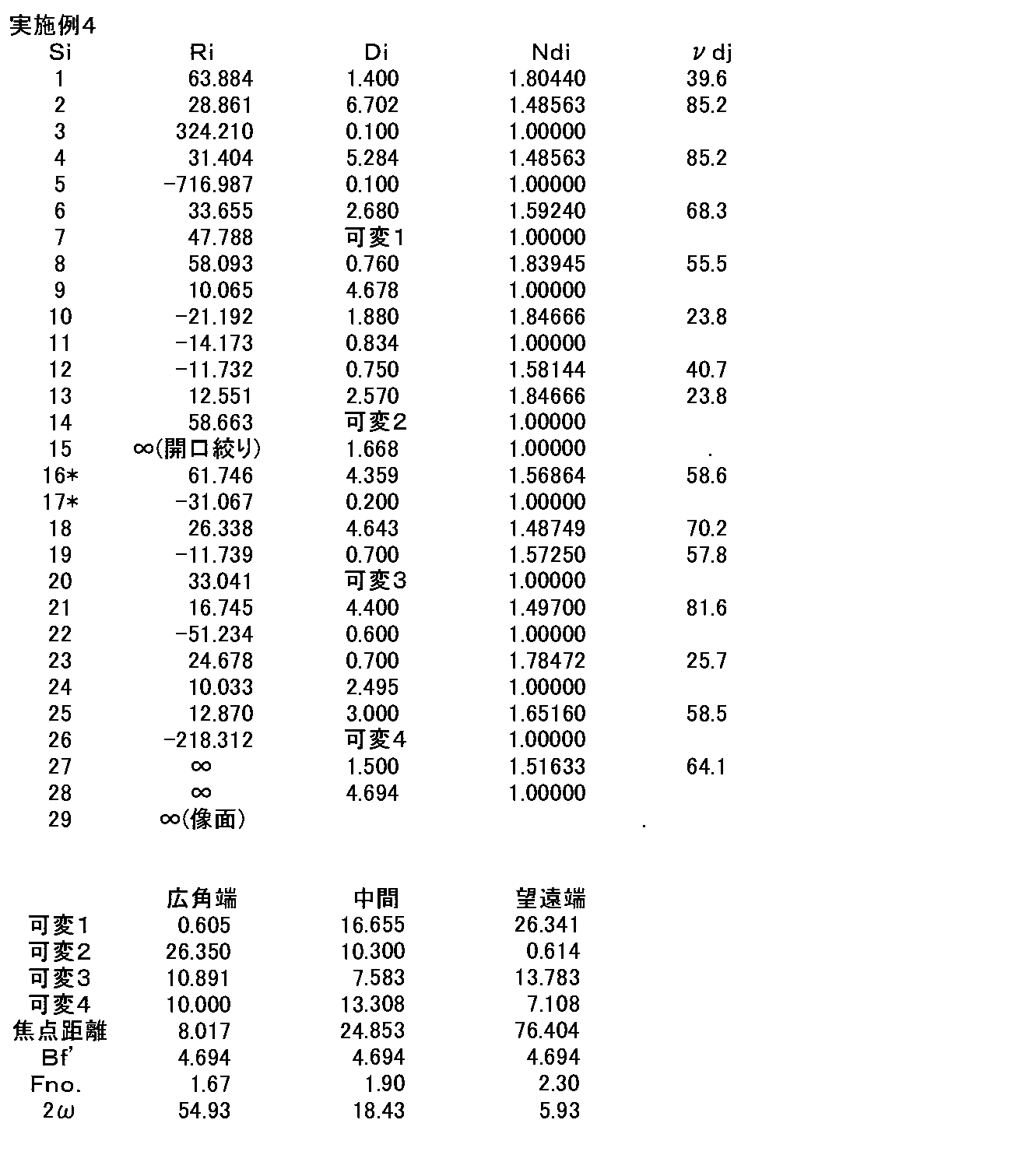





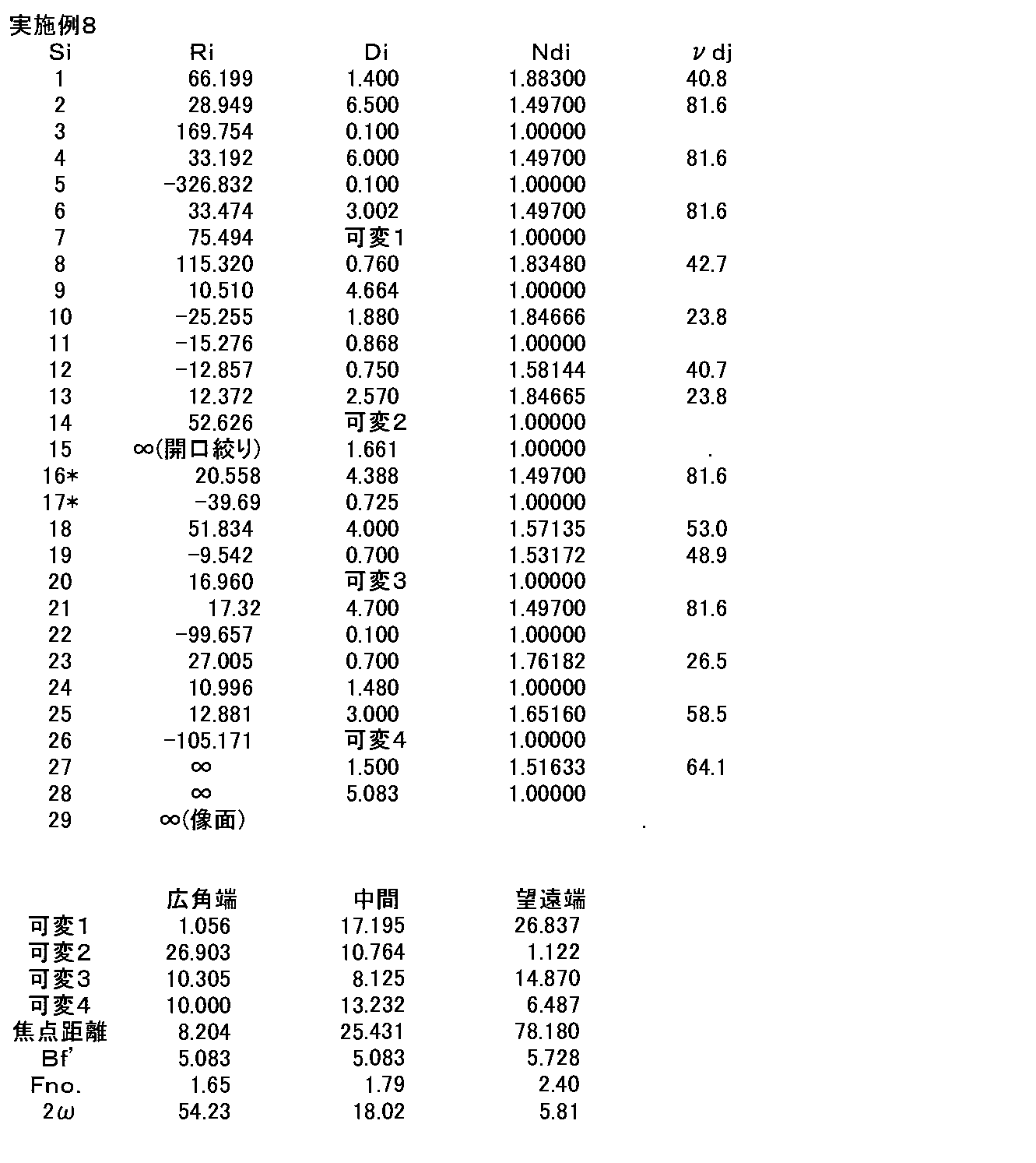


実施例1~9の変倍光学系の条件式(1)~(12)に対応する値、関連する値を表19に示す。なお、全ての実施例においてd線を基準波長としており、上記の変倍におけるデータの表および下記の表19に示す値はこの基準波長におけるものである。
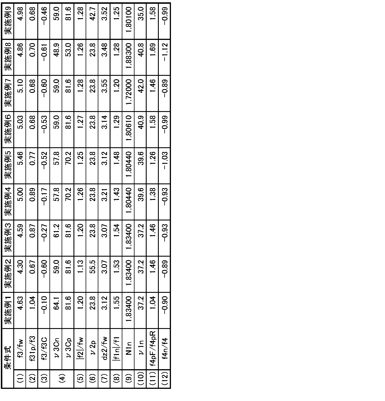
実施例1の変倍光学系の各収差図を図11(A)~図11(I)に示す。図11(A)、図11(B)、図11(C)はそれぞれ広角端における球面収差、像面湾曲、歪曲収差(ディストーション)を示し、図11(D)、図11(E)、図11(F)はそれぞれ中間焦点距離状態における球面収差、像面湾曲、歪曲収差(ディストーション)を示し、図11(G)、図11(H)、図11(I)はそれぞれ望遠端における球面収差、像面湾曲、歪曲収差(ディストーション)を示す。
球面収差の図ではd線に関する収差を実線で、g線(波長435.8nm)に関する収差を短い破線で、C線(波長656.3nm)に関する収差を長い破線で、波長880nmに関する収差を一点鎖線で示している。像面湾曲の図では、d線、g線、C線に関する収差を示し、サジタル方向については実線で、タンジェンシャル方向については点線で示している。歪曲収差の図はd線に関するものである。球面収差の図の縦軸はF値に対応する。像面湾曲と歪曲収差の図において、縦軸は像高(単位はmm)であり、縦軸の最小値は0である。
像高0は光軸上であるから、像高0におけるサジタル方向とタンジェンシャル方向の像面湾曲の値は一致する。像面湾曲の図の像高0における収差曲線の波長ごとの配列順は、球面収差の図の縦軸の最も下の位置における収差曲線の波長ごとの配列順と同じである。例えば、球面収差の図の縦軸の最も下の位置においては、左から順に、d線、g線、C線の収差曲線が並んでいる場合は、同じ変倍状態での像面湾曲の図の像高0の位置においては、同様に左から順に、d線のサジタル方向とタンジェンシャル方向、g線のサジタル方向とタンジェンシャル方向、C線のサジタル方向とタンジェンシャル方向の収差曲線が並ぶことになる。
なお、歪曲収差の図はTVディストーションで記載してある。光軸に垂直な平面物体の光学系によって結ばれる光軸に垂直な物体像のゆがみの程度を歪曲収差として表すが、写真レンズ等は一般的な、理想像高と実像高との差を理想像高で割った数値を百分率で表したものであるのに対して、TVレンズの分野ではこれとは異なった定義式を用い、これをTVディストーションとして区別している。この定義によれば、TV画面における長辺の曲がり量を対象として歪曲量として扱う。
具体的には、TVディストーションDTVは、長辺の曲がりの深さΔhを垂直画面長2hで割って百分率で表したもので、下記式の通り表される。
DTV=Δh/2h×100
歪曲収差図は、光軸からの実像高Yを光軸中心からの画面4対角方向の4点とし、これらの4点で結ばれた平面像の物体側での矩形平面物体を想定し、この像の長辺の中央部での実像高がhであり、対角上の点の光軸までの垂直高さからの差がΔhである。従って、画面の縦横比で異なる数値になるが、図11(C)、図11(F)、図11(I)に示す歪曲収差の図では、TV画面で一般的な3:4の比率で算出したものとなっている。
DTV=Δh/2h×100
歪曲収差図は、光軸からの実像高Yを光軸中心からの画面4対角方向の4点とし、これらの4点で結ばれた平面像の物体側での矩形平面物体を想定し、この像の長辺の中央部での実像高がhであり、対角上の点の光軸までの垂直高さからの差がΔhである。従って、画面の縦横比で異なる数値になるが、図11(C)、図11(F)、図11(I)に示す歪曲収差の図では、TV画面で一般的な3:4の比率で算出したものとなっている。
同様に、実施例2の変倍光学系の広角端、中間焦点距離状態、望遠端における各収差図を図12(A)~図12(I)に示し、実施例3の変倍光学系の広角端、中間焦点距離状態、望遠端における各収差図を図13(A)~図13(I)に示し、実施例4の変倍光学系の広角端、中間焦点距離状態、望遠端における各収差図を図14(A)~図14(I)に示し、実施例5の変倍光学系の広角端、中間焦点距離状態、望遠端における各収差図を図15(A)~図15(I)に示し、実施例6の変倍光学系の広角端、中間焦点距離状態、望遠端における各収差図を図16(A)~図16(I)に示し、実施例7の変倍光学系の広角端、中間焦点距離状態、望遠端における各収差図を図17(A)~図17(I)に示し、実施例8の変倍光学系の広角端、中間焦点距離状態、望遠端における各収差図を図18(A)~図18(I)に示し、実施例9の変倍光学系の広角端、中間焦点距離状態、望遠端における各収差図を図19(A)~図19(I)に示す。
次に、本発明の実施形態にかかる撮像装置について説明する。図20に、本発明の実施形態の撮像装置の一例として、本発明の実施形態の変倍光学系1を用いた撮像装置10の概略構成図を示す。撮像装置としては、例えば、監視カメラ、ビデオカメラ、電子スチルカメラ等を挙げることができる。
図20に示す撮像装置10は、変倍光学系1と、変倍光学系1の像側に配置されたフィルタ2と、変倍光学系によって結像される被写体の像を撮像する撮像素子3と、撮像素子3からの出力信号を演算処理する信号処理部4と、変倍光学系1の変倍を行うための変倍制御部5と、フォーカス調整を行うためのフォーカス制御部6とを備える。
変倍光学系1は、変倍時に固定されている正の第1レンズ群G1と、変倍時に光軸Zに沿って移動する負の第2レンズ群G2と、開口絞りStと、変倍時に固定されている正の第3レンズ群G3と、フォーカス調整時に光軸Zに沿って移動する正の第4レンズ群G4とを有するものである。なお、図20では各レンズ群を概略的に示している。撮像素子3は、変倍光学系1により形成される光学像を撮像して電気信号に変換するものであり、その撮像面は変倍光学系の像面に一致するように配置される。撮像素子3としては例えばCCDやCMOS等を用いることができる。
以上、実施形態および実施例を挙げて本発明を説明したが、本発明は上記実施形態および実施例に限定されず、種々の変形が可能である。例えば、各レンズ成分の曲率半径、面間隔、屈折率、アッベ数、非球面係数等の値は、上記各数値実施例で示した値に限定されず、他の値をとり得るものである。
Claims (9)
- 物体側から順に、正の屈折力を持つ第1レンズ群と、負の屈折力を持つ第2レンズ群と、絞りと、正の屈折力を持つ第3レンズ群と、正の屈折力を持つ第4レンズ群とを備え、
前記第1レンズ群、前記絞り、および前記第3レンズ群が像面に対して固定されており、変倍時に前記第2レンズ群および前記第4レンズ群が光軸方向に移動し、前記第4レンズ群が合焦機能を有するように構成された変倍光学系であって、
前記第3レンズ群は、少なくとも1面の非球面を有し、物体側から順に、正レンズと、正レンズおよび両凹レンズを貼り合わせた接合レンズとからなり、
下記条件式(1)~(4)を満たすことを特徴とする変倍光学系。
3.5<f3/fw<6 … (1)
0.4<f31p/f3<1.2 … (2)
-0.8<f3/f3C<0.1 … (3)
45<ν3Cn<ν3Cp … (4)
ただし、
f3:前記第3レンズ群の焦点距離
fw:広角端での全系の焦点距離
f31p:前記第3レンズ群の最も物体側の前記正レンズの焦点距離
f3C:前記接合レンズの焦点距離
ν3Cn:前記接合レンズを構成する前記両凹レンズのd線に対するアッベ数
ν3Cp:前記接合レンズを構成する前記正レンズのd線に対するアッベ数 - 下記条件式(4-1)を満たすことを特徴とする請求項1記載の変倍光学系。
55<ν3Cn<ν3Cp … (4-1) - 前記第3レンズ群の前記両凹レンズは、物体側より像側の面の曲率半径の絶対値が大きいものであることを特徴とする請求項1または2記載の変倍光学系。
- 前記第2レンズ群が、物体側から順に、負レンズと、物体側に凹面を向けた正メニスカスレンズと、両凹レンズと、正レンズとからなり、
下記条件式(5)~(7)を満たすことを特徴とする請求項1から3のいずれか1項記載の変倍光学系。
1.0<|f2|/fw<1.4 … (5)
20<ν2p<60 … (6)
2.8<dz2/fw<3.5 … (7)
ただし、
f2:前記第2レンズ群の焦点距離
ν2p:前記第2レンズ群の前記正メニスカスレンズのd線に対するアッベ数
dz2:広角端から望遠端へ変倍する際の前記第2レンズ群の光軸方向の移動量 - 下記条件式(6-1)を満たすことを特徴とする請求項4記載の変倍光学系。
20<ν2p<45 … (6-1) - 前記第1レンズ群が、物体側から順に、像側に凹面を向けた負レンズと、像側に凹面を向けた3枚の正レンズとからなり、
下記条件式(8)~(10)を満たすことを特徴とする請求項1から5のいずれか1項記載の変倍光学系。
1.0<|f1n|/f1<2.6 … (8)
1.7<N1n<2.0 … (9)
33<ν1n<43 … (10)
ただし、
f1n:前記第1レンズ群の前記負レンズの焦点距離
f1:前記第1レンズ群の焦点距離
N1n:前記第1レンズ群の前記負レンズのd線に対する屈折率
ν1n:前記第1レンズ群の前記負レンズのd線に対するアッベ数 - 下記条件式(9-1)を満たすことを特徴とする請求項6記載の変倍光学系。
1.8<N1n<2.0 … (9-1) - 前記第4レンズ群が、物体側から順に、両凸レンズと、像側に凹面を向けた負メニスカスレンズと、正レンズとからなり、
下記条件式(11)、(12)を満たすことを特徴とする請求項1から7のいずれか1項記載の変倍光学系。
0.8<f4pF/f4pR<2.0 … (11)
-1.3<f4n/f4<-0.6 … (12)
ただし、
f4pF:前記第4レンズ群の前記両凸レンズの焦点距離
f4pR:前記第4レンズ群の最も像側の前記正レンズの焦点距離
f4n:前記第4レンズ群の前記負メニスカスレンズの焦点距離
f4:前記第4レンズ群の焦点距離 - 請求項1から8のいずれか1項に記載の変倍光学系を備えたことを特徴とする撮像装置。
Priority Applications (3)
| Application Number | Priority Date | Filing Date | Title |
|---|---|---|---|
| CN201280012619.3A CN103443686B (zh) | 2011-03-10 | 2012-03-06 | 可变放大率光学系统和成像设备 |
| JP2013503389A JP5694508B2 (ja) | 2011-03-10 | 2012-03-06 | 変倍光学系および撮像装置 |
| US13/971,871 US8681433B2 (en) | 2011-03-10 | 2013-08-21 | Variable magnification optical system and imaging apparatus |
Applications Claiming Priority (2)
| Application Number | Priority Date | Filing Date | Title |
|---|---|---|---|
| JP2011-052728 | 2011-03-10 | ||
| JP2011052728 | 2011-03-10 |
Related Child Applications (1)
| Application Number | Title | Priority Date | Filing Date |
|---|---|---|---|
| US13/971,871 Continuation US8681433B2 (en) | 2011-03-10 | 2013-08-21 | Variable magnification optical system and imaging apparatus |
Publications (1)
| Publication Number | Publication Date |
|---|---|
| WO2012120875A1 true WO2012120875A1 (ja) | 2012-09-13 |
Family
ID=46797846
Family Applications (1)
| Application Number | Title | Priority Date | Filing Date |
|---|---|---|---|
| PCT/JP2012/001519 Ceased WO2012120875A1 (ja) | 2011-03-10 | 2012-03-06 | 変倍光学系および撮像装置 |
Country Status (4)
| Country | Link |
|---|---|
| US (1) | US8681433B2 (ja) |
| JP (1) | JP5694508B2 (ja) |
| CN (1) | CN103443686B (ja) |
| WO (1) | WO2012120875A1 (ja) |
Cited By (3)
| Publication number | Priority date | Publication date | Assignee | Title |
|---|---|---|---|---|
| JP2016153862A (ja) * | 2015-02-20 | 2016-08-25 | 株式会社タムロン | ズームレンズ |
| US10833748B2 (en) | 2018-09-28 | 2020-11-10 | At&T Intellectual Property I, L.P. | Determining channel state information in 5G wireless communication systems with phase tracking |
| CN115698815A (zh) * | 2020-04-21 | 2023-02-03 | Lg 伊诺特有限公司 | 光学系统及包含其的相机模块 |
Families Citing this family (19)
| Publication number | Priority date | Publication date | Assignee | Title |
|---|---|---|---|---|
| US9316820B1 (en) | 2014-03-16 | 2016-04-19 | Hyperion Development, LLC | Optical assembly for a wide field of view point action camera with low astigmatism |
| US10545314B1 (en) | 2014-03-16 | 2020-01-28 | Navitar Industries, Llc | Optical assembly for a compact wide field of view digital camera with low lateral chromatic aberration |
| US9316808B1 (en) | 2014-03-16 | 2016-04-19 | Hyperion Development, LLC | Optical assembly for a wide field of view point action camera with a low sag aspheric lens element |
| US10139595B1 (en) | 2014-03-16 | 2018-11-27 | Navitar Industries, Llc | Optical assembly for a compact wide field of view digital camera with low first lens diameter to image diagonal ratio |
| US9726859B1 (en) | 2014-03-16 | 2017-08-08 | Navitar Industries, Llc | Optical assembly for a wide field of view camera with low TV distortion |
| US10386604B1 (en) | 2014-03-16 | 2019-08-20 | Navitar Industries, Llc | Compact wide field of view digital camera with stray light impact suppression |
| US9494772B1 (en) | 2014-03-16 | 2016-11-15 | Hyperion Development, LLC | Optical assembly for a wide field of view point action camera with low field curvature |
| US9995910B1 (en) | 2014-03-16 | 2018-06-12 | Navitar Industries, Llc | Optical assembly for a compact wide field of view digital camera with high MTF |
| EP3203292B1 (en) * | 2014-10-03 | 2023-02-22 | Sony Group Corporation | Medical-use stereoscopic microscope optical system and medical-use observation device |
| CN105785555B (zh) * | 2016-03-28 | 2018-04-03 | 中山联合光电科技股份有限公司 | 一种大像面、高倍率、高分辨率的光学系统 |
| JP6452646B2 (ja) | 2016-06-01 | 2019-01-16 | キヤノン株式会社 | 光学系及びそれを有する撮像装置 |
| JP6452645B2 (ja) | 2016-06-01 | 2019-01-16 | キヤノン株式会社 | 光学系及びそれを有する撮像装置 |
| JP6381582B2 (ja) * | 2016-06-01 | 2018-08-29 | キヤノン株式会社 | 光学系及びそれを有する撮像装置 |
| JP6891078B2 (ja) | 2017-09-11 | 2021-06-18 | キヤノン株式会社 | 光学系及びそれを有する撮像装置 |
| JP6469284B1 (ja) * | 2018-01-29 | 2019-02-13 | キヤノン株式会社 | 投射レンズ及びこれを用いた投射型表示装置 |
| WO2019187874A1 (ja) * | 2018-03-28 | 2019-10-03 | ソニー株式会社 | 硬性鏡用光学系、撮像装置及び内視鏡システム |
| CN109633875B (zh) * | 2019-01-14 | 2023-10-27 | 广东奥普特科技股份有限公司 | 一种可连续变倍的远心镜头 |
| EP4063931B1 (en) * | 2019-11-18 | 2026-03-25 | LG Innotek Co., Ltd. | Optical system and camera module including same |
| CN111929859B (zh) * | 2020-09-22 | 2021-04-02 | 江西联益光学有限公司 | 长焦镜头及移动终端 |
Citations (11)
| Publication number | Priority date | Publication date | Assignee | Title |
|---|---|---|---|---|
| JPH08248318A (ja) * | 1995-03-08 | 1996-09-27 | Sony Corp | ズームレンズ |
| JP2001221948A (ja) * | 2000-02-10 | 2001-08-17 | Matsushita Electric Ind Co Ltd | ズームレンズ |
| JP2001356268A (ja) * | 2000-06-12 | 2001-12-26 | Olympus Optical Co Ltd | ズーム撮像光学系 |
| JP2005128186A (ja) * | 2003-10-22 | 2005-05-19 | Matsushita Electric Ind Co Ltd | ズームレンズ、並びにそれを用いたビデオカメラ及びデジタルスチルカメラ |
| JP2006113111A (ja) * | 2004-10-12 | 2006-04-27 | Matsushita Electric Ind Co Ltd | ズームレンズ系、撮像装置及びカメラ |
| JP2007298831A (ja) * | 2006-05-01 | 2007-11-15 | Nikon Corp | ズームレンズとこれを具備する光学装置 |
| JP2008310222A (ja) * | 2007-06-18 | 2008-12-25 | Canon Inc | ズームレンズ及びそれを有する撮像装置 |
| JP2009180897A (ja) * | 2008-01-30 | 2009-08-13 | Tamron Co Ltd | ズームレンズ |
| JP2009204942A (ja) * | 2008-02-28 | 2009-09-10 | Canon Inc | ズームレンズ及びそれを有する撮像装置 |
| JP2010102096A (ja) * | 2008-10-23 | 2010-05-06 | Fujinon Corp | ズームレンズおよび撮像装置 |
| JP2010145759A (ja) * | 2008-12-19 | 2010-07-01 | Nikon Corp | ズームレンズ、このズームレンズを備えた光学機器、及び、ズームレンズの製造方法 |
Family Cites Families (5)
| Publication number | Priority date | Publication date | Assignee | Title |
|---|---|---|---|---|
| JP4454731B2 (ja) | 1999-09-21 | 2010-04-21 | キヤノン株式会社 | ズームレンズ |
| JP2003295055A (ja) | 2002-04-03 | 2003-10-15 | Matsushita Electric Ind Co Ltd | 非球面ズームレンズ及びそれを用いたビデオカメラ |
| JP2006267676A (ja) * | 2005-03-24 | 2006-10-05 | Fujinon Corp | 像ぶれ補正機能付き変倍光学系 |
| US8503099B2 (en) | 2006-05-01 | 2013-08-06 | Nikon Corporation | Zoom lens system and optical apparatus using the same |
| JP5274200B2 (ja) * | 2008-10-23 | 2013-08-28 | キヤノン株式会社 | ズームレンズ及びそれを有する撮像装置 |
-
2012
- 2012-03-06 JP JP2013503389A patent/JP5694508B2/ja not_active Expired - Fee Related
- 2012-03-06 WO PCT/JP2012/001519 patent/WO2012120875A1/ja not_active Ceased
- 2012-03-06 CN CN201280012619.3A patent/CN103443686B/zh not_active Expired - Fee Related
-
2013
- 2013-08-21 US US13/971,871 patent/US8681433B2/en not_active Expired - Fee Related
Patent Citations (11)
| Publication number | Priority date | Publication date | Assignee | Title |
|---|---|---|---|---|
| JPH08248318A (ja) * | 1995-03-08 | 1996-09-27 | Sony Corp | ズームレンズ |
| JP2001221948A (ja) * | 2000-02-10 | 2001-08-17 | Matsushita Electric Ind Co Ltd | ズームレンズ |
| JP2001356268A (ja) * | 2000-06-12 | 2001-12-26 | Olympus Optical Co Ltd | ズーム撮像光学系 |
| JP2005128186A (ja) * | 2003-10-22 | 2005-05-19 | Matsushita Electric Ind Co Ltd | ズームレンズ、並びにそれを用いたビデオカメラ及びデジタルスチルカメラ |
| JP2006113111A (ja) * | 2004-10-12 | 2006-04-27 | Matsushita Electric Ind Co Ltd | ズームレンズ系、撮像装置及びカメラ |
| JP2007298831A (ja) * | 2006-05-01 | 2007-11-15 | Nikon Corp | ズームレンズとこれを具備する光学装置 |
| JP2008310222A (ja) * | 2007-06-18 | 2008-12-25 | Canon Inc | ズームレンズ及びそれを有する撮像装置 |
| JP2009180897A (ja) * | 2008-01-30 | 2009-08-13 | Tamron Co Ltd | ズームレンズ |
| JP2009204942A (ja) * | 2008-02-28 | 2009-09-10 | Canon Inc | ズームレンズ及びそれを有する撮像装置 |
| JP2010102096A (ja) * | 2008-10-23 | 2010-05-06 | Fujinon Corp | ズームレンズおよび撮像装置 |
| JP2010145759A (ja) * | 2008-12-19 | 2010-07-01 | Nikon Corp | ズームレンズ、このズームレンズを備えた光学機器、及び、ズームレンズの製造方法 |
Cited By (3)
| Publication number | Priority date | Publication date | Assignee | Title |
|---|---|---|---|---|
| JP2016153862A (ja) * | 2015-02-20 | 2016-08-25 | 株式会社タムロン | ズームレンズ |
| US10833748B2 (en) | 2018-09-28 | 2020-11-10 | At&T Intellectual Property I, L.P. | Determining channel state information in 5G wireless communication systems with phase tracking |
| CN115698815A (zh) * | 2020-04-21 | 2023-02-03 | Lg 伊诺特有限公司 | 光学系统及包含其的相机模块 |
Also Published As
| Publication number | Publication date |
|---|---|
| JPWO2012120875A1 (ja) | 2014-07-17 |
| US20130335831A1 (en) | 2013-12-19 |
| CN103443686A (zh) | 2013-12-11 |
| CN103443686B (zh) | 2015-10-14 |
| US8681433B2 (en) | 2014-03-25 |
| JP5694508B2 (ja) | 2015-04-01 |
Similar Documents
| Publication | Publication Date | Title |
|---|---|---|
| JP5694508B2 (ja) | 変倍光学系および撮像装置 | |
| JP5698342B2 (ja) | 変倍光学系および撮像装置 | |
| JP6192338B2 (ja) | ズームレンズ及びそれを有する撮像装置 | |
| CN110501810B (zh) | 光学系统和摄像装置 | |
| JP2014202841A5 (ja) | ||
| JP5745188B2 (ja) | ズームレンズおよび撮像装置 | |
| JP5303310B2 (ja) | ズームレンズ | |
| JP4817551B2 (ja) | ズームレンズ | |
| JPWO2013031180A1 (ja) | ズームレンズおよび撮像装置 | |
| WO2013031185A1 (ja) | ズームレンズおよび撮像装置 | |
| JP6649287B2 (ja) | ズームレンズおよび撮像装置 | |
| JP5462081B2 (ja) | ズームレンズおよび撮像装置 | |
| JP5566814B2 (ja) | 変倍光学系および撮像装置 | |
| JP5143532B2 (ja) | ズームレンズおよび撮像装置 | |
| JP5767330B2 (ja) | ズームレンズおよび撮像装置 | |
| JP4537114B2 (ja) | ズームレンズ | |
| JP4585796B2 (ja) | ズームレンズ及びそれを有する撮像装置 | |
| JP2010066661A (ja) | ズームレンズおよび撮像装置 | |
| JP5063211B2 (ja) | ズームレンズおよび撮像装置 | |
| WO2013031183A1 (ja) | ズームレンズおよび撮像装置 | |
| JP2020030285A (ja) | ズームレンズ及び撮像装置 | |
| JP5767710B2 (ja) | ズームレンズおよび撮像装置 | |
| JP5767334B2 (ja) | ズームレンズおよび撮像装置 | |
| JPWO2013031178A1 (ja) | ズームレンズおよび撮像装置 | |
| WO2013031186A1 (ja) | ズームレンズおよび撮像装置 |
Legal Events
| Date | Code | Title | Description |
|---|---|---|---|
| 121 | Ep: the epo has been informed by wipo that ep was designated in this application |
Ref document number: 12755505 Country of ref document: EP Kind code of ref document: A1 |
|
| ENP | Entry into the national phase |
Ref document number: 2013503389 Country of ref document: JP Kind code of ref document: A |
|
| NENP | Non-entry into the national phase |
Ref country code: DE |
|
| 122 | Ep: pct application non-entry in european phase |
Ref document number: 12755505 Country of ref document: EP Kind code of ref document: A1 |