WO2012118206A1 - 状態推定装置、状態推定方法及びプログラム - Google Patents
状態推定装置、状態推定方法及びプログラム Download PDFInfo
- Publication number
- WO2012118206A1 WO2012118206A1 PCT/JP2012/055462 JP2012055462W WO2012118206A1 WO 2012118206 A1 WO2012118206 A1 WO 2012118206A1 JP 2012055462 W JP2012055462 W JP 2012055462W WO 2012118206 A1 WO2012118206 A1 WO 2012118206A1
- Authority
- WO
- WIPO (PCT)
- Prior art keywords
- driver
- identification
- result
- group
- state
- Prior art date
Links
Images


Classifications
-
- G—PHYSICS
- G06—COMPUTING; CALCULATING OR COUNTING
- G06V—IMAGE OR VIDEO RECOGNITION OR UNDERSTANDING
- G06V20/00—Scenes; Scene-specific elements
- G06V20/50—Context or environment of the image
- G06V20/59—Context or environment of the image inside of a vehicle, e.g. relating to seat occupancy, driver state or inner lighting conditions
- G06V20/597—Recognising the driver's state or behaviour, e.g. attention or drowsiness
-
- G—PHYSICS
- G06—COMPUTING; CALCULATING OR COUNTING
- G06F—ELECTRIC DIGITAL DATA PROCESSING
- G06F18/00—Pattern recognition
- G06F18/20—Analysing
- G06F18/24—Classification techniques
- G06F18/243—Classification techniques relating to the number of classes
- G06F18/2431—Multiple classes
-
- G—PHYSICS
- G06—COMPUTING; CALCULATING OR COUNTING
- G06F—ELECTRIC DIGITAL DATA PROCESSING
- G06F18/00—Pattern recognition
- G06F18/20—Analysing
- G06F18/25—Fusion techniques
- G06F18/254—Fusion techniques of classification results, e.g. of results related to same input data
-
- G—PHYSICS
- G06—COMPUTING; CALCULATING OR COUNTING
- G06V—IMAGE OR VIDEO RECOGNITION OR UNDERSTANDING
- G06V10/00—Arrangements for image or video recognition or understanding
- G06V10/70—Arrangements for image or video recognition or understanding using pattern recognition or machine learning
- G06V10/764—Arrangements for image or video recognition or understanding using pattern recognition or machine learning using classification, e.g. of video objects
-
- G—PHYSICS
- G06—COMPUTING; CALCULATING OR COUNTING
- G06V—IMAGE OR VIDEO RECOGNITION OR UNDERSTANDING
- G06V10/00—Arrangements for image or video recognition or understanding
- G06V10/70—Arrangements for image or video recognition or understanding using pattern recognition or machine learning
- G06V10/77—Processing image or video features in feature spaces; using data integration or data reduction, e.g. principal component analysis [PCA] or independent component analysis [ICA] or self-organising maps [SOM]; Blind source separation
- G06V10/80—Fusion, i.e. combining data from various sources at the sensor level, preprocessing level, feature extraction level or classification level
- G06V10/809—Fusion, i.e. combining data from various sources at the sensor level, preprocessing level, feature extraction level or classification level of classification results, e.g. where the classifiers operate on the same input data
-
- G—PHYSICS
- G08—SIGNALLING
- G08B—SIGNALLING OR CALLING SYSTEMS; ORDER TELEGRAPHS; ALARM SYSTEMS
- G08B21/00—Alarms responsive to a single specified undesired or abnormal condition and not otherwise provided for
- G08B21/02—Alarms for ensuring the safety of persons
- G08B21/06—Alarms for ensuring the safety of persons indicating a condition of sleep, e.g. anti-dozing alarms
-
- G—PHYSICS
- G08—SIGNALLING
- G08G—TRAFFIC CONTROL SYSTEMS
- G08G1/00—Traffic control systems for road vehicles
- G08G1/16—Anti-collision systems
Definitions
- the present invention relates to a state estimation device, a state estimation method, and a program, and more particularly, to a state estimation device that estimates a driver state, and a state estimation method and program for estimating a driver state.
- the estimation apparatus described in Patent Literature 1 is a state in which the driver's state is in a state of low attention, based on the driver's biological information and the output from the discriminator that receives information related to the vehicle that the driver drives. It is estimated whether it exists in. Specifically, the estimation apparatus performs weighting based on the reliability of the output result, and then estimates the result indicated by the majority of the output result from the discriminator as the driver state.
- the device described in Patent Document 2 estimates the degree of sleepiness felt by the driver based on a plurality of feature amounts related to the eyes, such as the time required for blinking and the degree of eye open / close.
- the driver state is estimated based on the output from the classifier. For this reason, it is difficult to estimate whether or not the driver is in a random state, and it is difficult to estimate the driver state in multiple stages.
- the estimation apparatus described in Patent Document 2 can estimate the driver state in multiple stages. However, the state of the driver changes almost continuously. Therefore, it is rare to transition from a state with a high degree of arousal to a state in which the degree of arousal is extremely reduced in a short time, or from a state with a very low arousal level to a state in which it has been awakened in a short time. Conceivable. Therefore, in order to accurately estimate the driver state, it is necessary to consider the continuity of the state transition.
- the present invention has been made under the above circumstances, and an object thereof is to accurately estimate the state of the driver in consideration of the continuous transition of the state of the driver.
- a state estimation device for estimating the state of a driver, A first group and a second group in which a plurality of classes defined using the feature amount related to the driver as an input value and the driver's activity level as an index are identified.
- the first group identifies the group to which the driver state belongs. 1 identification means;
- Estimation means for estimating a class to which the driver state belongs based on the identification result of the first identification means and the identification result of the second identification means; Verification means for verifying an estimation result of the estimation means; Output means for outputting an estimation result according to the verification result of the verification means; Is provided.
- a state estimation method includes: A state estimation method for estimating a driver state, A first group and a second group in which a plurality of classes defined using the feature amount related to the driver as an input value and the driver's activity level as an index are identified.
- the first group identifies the group to which the driver state belongs.
- 1 identification step A third group and a fourth group into which a plurality of classes defined using the feature amount related to the driver as an input value and the driver activity level as an index are identified.
- a program provides: On the computer, A first group for identifying the group to which the driver state belongs, out of a first group and a second group into which a plurality of classes determined by using a characteristic amount related to the driver as an input value and using the driver activity level as an index. Identification procedure, A third group and a fourth group into which a plurality of classes defined using the feature amount related to the driver as an input value and the driver activity level as an index are identified.
- Two identification procedures A step of estimating a class to which the driver state belongs based on a result of identification in the first identification procedure and a result of identification in the second identification procedure; Verifying the result of the estimation; A procedure for outputting an estimation result according to the verification result; Is executed.
- the estimation result estimated based on the identification result is verified. Therefore, when performing the verification, for example, by verifying the continuity of the transition of the driver state, the state of the driver can be accurately estimated.
- FIG. 1 is a block diagram showing a schematic configuration of a state estimation system 10 according to the present embodiment.
- the state estimation system 10 estimates the state of the driver based on, for example, the biological information of the driver driving the automobile. The estimation of this state estimates whether or not the driver is in a state of inducing a traffic accident due to sleepiness or fatigue.
- the driver state is class 1 for a state that does not seem to be totally sleepy, class 2 for a state that seems to be a little sleepy, and a state that seems to be sleepy.
- Class 3 is defined as class 4 which is very sleepy and class 5 is very sleepy, and it is estimated to which class the driver 60 belongs.
- the state estimation system 10 includes a photographing device 20 and an estimation device 30.
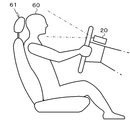
- the photographing device 20 photographs the face of the driver 60 seated on the seat 61. Then, an image obtained by photographing is converted into an electrical signal and output to the estimation device 30. As shown in FIG. 2, the photographing device 20 is installed, for example, on a handle column. Then, the viewing angle and the posture are adjusted so that the face of the driver 60 is positioned at the center of the viewing field.
- the estimation device 30 includes a feature amount output unit 31, identification units 32 a and 32 b, an estimated value calculation unit 33, a state estimation unit 34, a verification unit 35, and an estimation result output unit 36. .
- the feature amount output unit 31 extracts the biological information of the driver 60 as a feature amount from the image information output from the imaging device 20, for example, every 10 seconds. And the extracted feature-value is output to identification part 32a, 32b. Specifically, the feature amount output unit 31 determines, based on the image information, the eyelid opening degree a1 of the driver 60, the number of blinks a2 per unit time, the required time a3 from the start to the end of the blink, and the line-of-sight direction a4. , Biometric information such as face orientation a5 is extracted. Then, the extracted biological information a1 to a5 is sequentially output as the feature amount x N (a1, a2, a3, a4, a5).
- the feature amount x 1 (a1, a2, a3 , a4, a5), x 2 (a1, a2, a3, a4, a5), ⁇ , x N (a1, a2, a3, a4, a5) Is calculated approximately every 10 seconds and output to each of the identification units 32a and 32b.
- the feature amount x N (a1, a2, a3 , a4, a5), and displays the x N.
- N represents an integer of 1 or more.
- the first group composed of class 1, class 2 and class 3 the second group composed of class 4 and class 5, class 1, class 2, a third group composed of class 3 and class 4 and a four group composed of class 5 are defined.
- the estimation of the state of the driver 60 is performed based on the result obtained by the identification units 32a and 32b described below identifying the group to which the state of the driver 60 belongs.
- the identification unit 32a identifies whether the state of the driver 60 belongs to the first group consisting of class 1, class 2 and class 3, or belongs to the second group consisting of class 4 and class 5.
- the identification unit 32 a outputs the identification result ⁇ N (x) to the estimated value calculation unit 33 when the feature amount x N is input.
- the discriminator 32a for example, a weak discriminator that has been learned by AdaBoost can be used.
- the sign of ⁇ N (x) indicates the group to which the driver state belongs. For example, when the sign of ⁇ N (x) is ⁇ , it means that the state of the driver belongs to the first group, and when the sign of ⁇ N (x) is +, the state of the driver is It means belonging to the second group.
- the identification result alpha N (x) is the absolute value of ⁇ N (x)
- of magnitude indicates the reliability of the identification results. For example, when the sign of ⁇ N (x) is ⁇ , the larger the absolute value
- the identification unit 32b identifies whether the driver state belongs to the third group consisting of class 1, class 2, class 3, and class 4 or belongs to the fourth group consisting of class 5.
- the identification unit 32 b outputs the identification result ⁇ N (x) to the estimated value calculation unit 33 when the feature amount x is input.
- a weak classifier that has been learned by AdaBoost can be used as the identification unit 32b.
- the sign of ⁇ N (x) indicates the group to which the driver state belongs. For example, if the sign of ⁇ N (x) is ⁇ , it means that the state of the driver belongs to the third group, and if the sign of ⁇ N (x) is +, the state of the driver is the first state. It means belonging to 4 groups.
- the identification result beta N (x) is the absolute value of ⁇ N (x)
- of magnitude indicates the reliability of the identification results. For example, when the sign of ⁇ N (x) is ⁇ , the larger the absolute value
- the estimated value calculation unit 33 sequentially acquires the identification result ⁇ N (x) output from the identification unit 32a. Then, four identification result including the latest identification result ⁇ N (x) ⁇ N ( x), ⁇ N-1 (x), ⁇ N-2 (x), ⁇ N-3 using a (x) following The calculation shown by Formula (1) is performed. Thereby, the average value AVG ⁇ N of the four identification results ⁇ N (x), ⁇ N-1 (x), ⁇ N-2 (x), ⁇ N-3 (x) output from the identification unit 32a is calculated. Is done. Note that n is 4.
- the estimated value calculation unit 33 sequentially acquires the identification result ⁇ N (x) output from the identification unit 32b. Then, the latest identification result beta N (x) 4 single identification result including ⁇ N (x), ⁇ N -1 (x), ⁇ N-2 (x), ⁇ N-3 using a (x) following The calculation shown by Formula (2) is performed. Thus, the average value AVG ⁇ N of the four identification results ⁇ N (x), ⁇ N-1 (x), ⁇ N-2 (x), ⁇ N-3 (x) output from the identification unit 32b is calculated. Is done.
- the estimated value calculation unit 33 calculates the estimated values D34 N and D45 N by performing the operations shown in the following equations (3) and (4).
- the sign (X) function included in the above equations (3) and (4) outputs 1 when the sign of X is +, and outputs -1 when the sign of AVG ⁇ N is-. .
- X is zero
- the value of the estimation results D34 N and D45 N shown in the above equation (1) is one of 1, ⁇ 1, 0.
- the variable of the sign function in the above equation (1) is It is rare to become zero. Therefore, it can be considered that the values of the estimation results D34 N and D45 N are either 1 or -1.
- the state estimation unit 34 estimates the state of the driver 60 based on the estimated values D34 N and D45 N and the average values AVG ⁇ N and AVG ⁇ N.
- the identification result ⁇ N (x) means that the state of the driver 60 belongs to the first group when the sign is ⁇ .
- the identification result ⁇ N (x) means that the state of the driver 60 belongs to the second group when the sign is +. Therefore, the estimated value D34 N determined by the sign of the average value AVG ⁇ N of the identification result ⁇ N (x) indicates that the state of the driver 60 belongs to the first group when the sign is ⁇ . When the sign is +, it indicates that the state of the driver 60 belongs to the second group.
- the identification result ⁇ N (x) means that the state of the driver 60 belongs to the third group when the sign is ⁇ . Further, the identification result ⁇ N (x) means that the state of the driver 60 belongs to the fourth group when the sign is +. Therefore, the estimated value D45 N determined by the sign of the average value AVG ⁇ N of the identification result ⁇ N (x) indicates that the state of the driver 60 belongs to the third group when the sign is ⁇ . When the sign is +, it indicates that the state of the driver 60 belongs to the fourth group.
- the state estimating unit 34 assigns the class of the driver 60 to the classes 1 to 3 common to the first group and the third group. Presume that the state belongs.
- the estimated value D34 N is ⁇ 1 and the estimated value D45 N is 1, it can be determined that the state of the driver 60 belongs to the first group and the fourth group. However, as can be seen with reference to FIG. 3, there is no common part between the first group and the fourth group. In this case, state estimation unit 34, the absolute value of the average value AVG ⁇ N
- found the following, the absolute value of the average value AVG ⁇ N
- the state of the driver 60 belongs to the second group and the third group.
- the second group is composed of classes 4 and 5
- the third group is composed of classes 1 to 4. Therefore, when the estimated value D34 N is 1 and the estimated value D45 N is ⁇ 1, the state estimating unit 34 belongs to the class 4 common to the second group and the third group. It is estimated that
- the state estimating unit 34 includes the state of the driver 60 in class 5 common to the second group and the fourth group. Estimated.
- the state estimation unit 34 performs the above-described estimation and outputs an estimation result RST N to the verification unit 35.
- the verification unit 35 verifies the estimation result RST N of the state estimation unit 34. Specifically, the verification unit 35 first by performing an operation represented by the following equation (5), calculates and outputs the verification value CL N.
- the estimation result output unit 36 determines that the reliability of the estimation result RST N estimated by the state estimation unit 34 is low when the value of the verification value CL N output from the verification unit 35 is ⁇ 1.
- the estimation result RST N ⁇ 1 estimated before the estimation result RST N is estimated is output to an external device or the like.
- the estimation result output unit 36 is estimated before the estimation result RST N estimated by the state estimation unit 34 and the estimation result RST N are estimated.
- the estimated result RST N-1 is compared.
- the estimation result RST N is output to an external device or the like.
- the estimation result output unit 36 compares the estimation result RST N with the estimation result RST N ⁇ 1 . As a result, if the class to which the driver 60 belongs cannot be determined to have continuously changed, the estimation result output unit RST N N-1 is output to an external device or the like.
- the state of the driver 60 is estimated to belong to classes 1 to 3, a case estimated to belong to classes 4 and 5, a case estimated to belong to class 4, A case presumed to belong to class 5 can be considered. Therefore, the estimation result output unit 36, for example, indicates that the estimation result RST N-1 is an estimation result that the state of the driver 60 belongs to classes 1 to 3, and the next estimation result RST N indicates that the state of the driver 60 is a class. 4 or the estimation result that the state of the driver 60 belongs to the classes 1 to 3, it is determined that the class to which the driver 60 belongs has continuously changed, and the estimation result RST N is output to an external device or the like.
- the estimation result output unit 36 for example, the estimation result RST N-1 is an estimation result that the state of the driver 60 belongs to classes 1 to 3, and the next estimation result RST N If it is an estimation result that belongs to 5, it is determined that the class to which the state of the driver 60 belongs has continuously changed, and the estimation result RST N-1 is output to an external device or the like.
- the external device or the like can output, for example, an alarm for preventing the patient to fall asleep or an announcement for prompting a break based on the estimation result.
- the estimated values D34 and D45 are calculated based on the average value of the plurality of identification results ⁇ (x) and the identification results ⁇ (x). Based on the estimated values D34 and D45, the class to which the driver 60 belongs is estimated. Therefore, when the identification results ⁇ (x) and ⁇ (x) are sequentially calculated, even if an identification result with a large error is output, the class to which the driver 60 belongs can be estimated accurately.
- the verification value CL is calculated by executing the calculation shown in the above equation (5). Then, the estimation result RST is corrected based on the verification value CL. Specifically, when it is determined that the reliability of the estimation result RST N is low based on the verification value CL, the estimation result RST N-1 estimated last time is output as the estimation result RST. This makes it possible to output an estimation result with high reliability.
- the estimation result RST N and the estimation result RST N-1 are compared, and when it is determined that the class to which the driver 60 belongs has continuously changed, the estimation result RST N is output.
- the estimation result RST N and the estimation result RST N-1 are compared, and when it is not determined that the class to which the driver 60 belongs has continuously changed, the previous estimation result RST N-1 is output. For this reason, it is possible to output a highly reliable estimation result.
- the estimation result RST N-1 is an estimation result that the state of the driver 60 belongs to classes 1 to 3
- the next estimation result RST N is determined that the state of the driver 60 belongs to class 4. It is considered to be an estimation result or an estimation result that the state of the driver 60 belongs to classes 1 to 3.
- the estimation result RST N-1 is an estimation result that the state of the driver 60 belongs to classes 1 to 3
- the next estimation result RST N is determined that the state of the driver 60 belongs to class 5. It is unlikely that this is an estimation result. Therefore, it is possible to output an estimation result with high reliability by outputting only an estimation result having continuity with respect to the latest estimation result.
- the state estimation system 10 according to the present embodiment is different from the state estimation system 10 according to the first embodiment in that the estimation device 30 is realized by a general computer, a microcomputer, or the like.
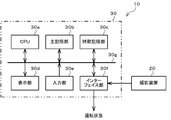
- FIG. 4 is a block diagram showing a physical configuration of the state estimation system 10. As shown in FIG. 4, the state estimation system 10 includes an imaging device 20 and an estimation device 30 including a computer.
- the estimation device 30 includes a CPU (Central Processing Unit) 30a, a main storage unit 30b, an auxiliary storage unit 30c, a display unit 30d, an input unit 30e, an interface unit 30f, and a system bus 30g that interconnects the above units. Yes.
- CPU Central Processing Unit
- the CPU 30a executes processing to be described later according to a program stored in the auxiliary storage unit 30c.
- the main storage unit 30b includes a RAM (Random Access Memory) and the like, and is used as a work area of the CPU 30a.
- RAM Random Access Memory
- the auxiliary storage unit 30c includes a non-volatile memory such as a ROM (Read Only Memory), a magnetic disk, and a semiconductor memory.
- the auxiliary storage unit 30c stores programs executed by the CPU 30a, various parameters, and the like. Further, information including image information output from the photographing apparatus 20 and a processing result by the CPU 30a is sequentially stored.
- the display unit 30d has, for example, an LCD (Liquid Crystal Display). Then, the processing result of the CPU 30a is displayed.
- LCD Liquid Crystal Display
- the input unit 30e has an input key and a pointing device.
- the operator's instruction is input via the input unit 30e, and is output to the CPU 30a via the system bus 30g.
- the interface unit 30f includes a serial interface or a LAN (Local Area Network) interface.
- the imaging device 20 is connected to the system bus 30g via the interface unit 30f.
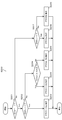
- the flowchart in FIG. 5 corresponds to a series of processing algorithms of a program executed by the CPU 30a.
- the process performed by the estimation device 30 will be described with reference to FIG. This process is executed after the CPU 30a outputs the image information from the photographing apparatus 20.
- step S101 CPU 30a, for example every 10 seconds, from the image information output from the photographing unit 20, extracts the biometric information of the driver 60 as the feature amount x N.
- CPU 30a the feature amount based on x N, the state of the driver 60, class 1, belongs to the first group of class 2 and class 3, or the second consisting of class 4 and class 5 Identify whether it belongs to a group. Then, the identification result ⁇ N (x) is calculated.
- CPU 30a based on the feature amount x N, the driver state, class 1, class 2, belongs to the third group of Class 3 and Class 4, or comprising such a class 5 belonging to the fourth group To identify. Then, the identification result ⁇ N (x) is calculated.
- the CPU 30a has four identification results ⁇ N (x), ⁇ N-1 (x), ⁇ N-2 (x), ⁇ N-3 including the latest identification result ⁇ N (x).
- (x) performs an operation represented by the above formula (1), calculates an average value AVG ⁇ N.
- the above four identification results ⁇ N (x), ⁇ N-1 (x), ⁇ N-2 (x), ⁇ N-3 (x) including the latest identification result ⁇ N (x) are used to The calculation represented by the equation (2) is executed to calculate the average value AVG ⁇ N.
- the CPU 30a calculates the estimated values D34 N and D45 N by performing the calculations shown in the above equations (3) and (4).
- the CPU 30a executes the process shown in the flowchart of FIG. 6 in order to calculate the estimation result RST.
- step S201 CPU 30a is the estimated value D34 N determines whether -1.
- step S201: Yes the CPU 30a proceeds to step S202.
- step S202 CPU 30a is the estimated value D45 N determines whether -1. If the estimated value D45 N is -1 (step S202: Yes), CPU 30a, the process proceeds to step S203, the state of the driver 60, it is estimated to belong to either class 1-3.
- step S202 if the estimated value D45 N is 1 (step S202: No), CPU 30a proceeds to step S204.
- step S204 CPU 30a, the absolute value of the average value AVG ⁇ N
- step S201 determines whether the estimated value D34 N is 1 in step S201 (step S201: No). If the estimated value D34 N is 1 in step S201 (step S201: No), the CPU 30a proceeds to step S207.
- step S207 CPU 30a is the estimated value D45 N determines whether -1. If the estimated value D45 N is -1 (step S207: Yes), CPU 30a, the process proceeds to step S208, the state of the driver 60, he is estimated to belong to the class 4. On the other hand, when the estimated value D45 N is 1 (step S207: No), CPU 30a, the process proceeds to step S209, the state of the driver 60, is estimated to belong to the class 5.
- the CPU 30a verifies the estimation result RST. Specifically, the CPU 30a calculates the verification value CL N by performing the calculation shown in the following equation (5).
- the CPU 30a determines that the reliability of the estimation result RST N is low and is estimated before the estimation result RST N is estimated.
- the estimated result RST N-1 is output to an external device or the like.
- the CPU 30a compares the estimation result RST N with the estimation result RST N ⁇ 1 estimated before the estimation result RST N is estimated. If the CPU 30a determines that the class to which the driver 60 belongs has continuously changed, the CPU 30a outputs the estimation result RST N to an external device or the like. Further, the CPU 30a compares the estimation result RST N with the estimation result RST N-1, and if the CPU 30a cannot determine that the class to which the driver 60 belongs has continuously changed, the CPU 30a obtains the previous estimation result RST N-1 . Output to an external device.
- the estimated values D34 and D45 are calculated based on the average value of the plurality of identification results ⁇ (x) and the identification results ⁇ (x). Based on the estimated values D34 and D45, the class to which the driver 60 belongs is estimated. Therefore, when the identification results ⁇ (x) and ⁇ (x) are sequentially calculated, even if an identification result with a large error is output, the class to which the driver 60 belongs can be estimated accurately.
- the verification value CL is calculated by executing the calculation shown in the above equation (5). Then, the estimation result RST is corrected based on the verification value CL. Specifically, when it is determined that the reliability of the estimation result RST N is low based on the verification value CL, the estimation result RST N-1 estimated last time is output as the estimation result RST. This makes it possible to output an estimation result with high reliability.
- the estimation result RST N and the estimation result RST N-1 are compared, and when it is determined that the class to which the driver 60 belongs has continuously changed, the estimation result RST N is output to an external device or the like. The Then, when the estimation result RST N and the estimation result RST N-1 are compared and it is not determined that the class to which the driver 60 belongs has continuously changed, the previous estimation result RST N-1 is transferred to an external device or the like. Is output. For this reason, it is possible to output a highly reliable estimation result.
- biometric information such as a driver's pulse and a respiration interval
- the verification value CL is calculated based on the formula (5).
- This formula (5) is an example, and a general formula for calculating the verification value CL is expressed by, for example, the following formula (6). Note that k is a constant.
- the estimation device 30 includes the two identification units 32a and 32b has been described. Not limited to this, the estimation device 30 may include three or more identification units.
- the function of the estimation device 30 according to each of the above embodiments can be realized by dedicated hardware or by a normal computer system.
- the programs stored in the auxiliary storage unit 30c of the estimation device 30 are flexible disk, CD-ROM (Compact Disk Read-Only Memory), DVD (Digital Versatile Disk), MO (Magneto-Optical Disk). ) Or the like may be stored and distributed in a computer-readable recording medium, and the program may be installed in the computer to constitute an apparatus that executes the above-described processing.
- the program may be stored in a disk device or the like of a predetermined server device on a communication network such as the Internet, and may be downloaded onto a computer by being superimposed on a carrier wave, for example.
- the program may be activated and executed while being transferred via a communication network.
- the program may be executed entirely or partially on the server device, and the above-described image processing may be executed while transmitting / receiving information related to the processing via the communication network.
- the state estimation device, state estimation method, and program of the present invention are suitable for estimating the driver state.
Abstract
推定結果に対する検証値を算出する。そして、算出した検証値に基づいて、推定結果を補正する。これにより、信頼性が高い推定結果を出力することが可能となる。また、ドライバが属するクラスが、連続的に推移したと判断できる場合には、推定結果を出力する。一方で、ドライバが属するクラスが連続的に推移したと判断できない場合には、最新の推定結果に代えて、以前の推定結果を出力する。これにより、信頼性が高い推定結果を出力することが可能となる。
Description
本発明は、状態推定装置、状態推定方法及びプログラムに関し、更に詳しくは、ドライバの状態を推定する状態推定装置、ドライバの状態を推定するための状態推定方法及びプログラムに関する。
近年、交通事故の死者数は減少傾向にあるものの、事故の発生件数自体は依然として高い水準で推移している。事故の原因は様々であるが、ドライバが漫然な状態(漫然状態)で車両の運転を行うことも、事故を誘発する原因の1つである。漫然状態は、運転中の会話や、携帯電話の使用など、ドライバが運転以外の行動を行うことにより、運転に対する注意力が散漫になる状態と、疲労や眠気などによってドライバの注意力が低下する状態とに概ね二分することができる。
疲労や眠気は、ドライバ自身での予防が困難である。このため、安全上の観点から、ドライバの居眠りや覚醒度の低下を正確に検出するためのシステムが種々提案されている(例えば特許文献1及び2参照)。
特許文献1に記載された推定装置は、ドライバの生体情報や、当該ドライバが運転する車両に関する情報を入力とする識別器からの出力に基づいて、ドライバの状態が、注意力が低下した漫然状態にあるか否かを推定する。具体的には、当該推定装置は、出力結果の信頼度に基づく重み付けを行ったうえで、識別器からの出力結果の多数派によって示される結果を、ドライバの状態として推定する。
また、特許文献2に記載された装置は、例えば瞬きに要する時間や眼の開閉度など、眼に関する複数の特徴量に基づいて、ドライバが感じている眠気の度合いを推定する。
特許文献1に記載された装置では、ドライバの状態の推定が、識別器からの出力に基づいて行われる。このため、ドライバが漫然状態にあるか否かを判断するに留まり、ドライバの状態を多段階に推定することが困難である。
特許文献2に記載された推定装置は、ドライバの状態を多段階に推定することができる。しかしながら、ドライバの状態は概ね連続的に移行する。そのため、覚醒度が高い状態から、短時間に極端に覚醒度が低下した状態に移行したり、覚醒度が極端に低下した状態から、短時間に覚醒した状態に移行することは稀であると考えられる。したがって、ドライバの状態を正確に推定するためには、状態の推移の連続性を考慮する必要がある。
本発明は、上述の事情の下になされたもので、ドライバの状態が連続的に推移することを考慮して、当該ドライバの状態を正確に推定することを目的とする。
上記目的を達成するため、本発明の第1の観点に係る状態推定装置は、
ドライバの状態を推定する状態推定装置であって、
前記ドライバに関する特徴量を入力値とし、前記ドライバの活性度合いを指標として定められた複数のクラスが分類される第1グループと第2グループのうち、前記ドライバの状態が属する前記グループを識別する第1の識別手段と、
前記ドライバに関する特徴量を入力値とし、前記ドライバの活性度合いを指標として定められた複数のクラスが分類される第3グループと第4グループのうち、前記ドライバの状態が属する前記グループを識別する第2の識別手段と、
前記第1の識別手段の識別結果、及び前記第2の識別手段の識別結果に基づいて、前記ドライバの状態が属するクラスを推定する推定手段と、
前記推定手段の推定結果を検証する検証手段と、
前記検証手段の検証結果に応じた推定結果を出力する出力手段と、
を備える。
上記目的を達成するため、本発明の第2の観点に係る状態推定方法は、
ドライバの状態を推定する状態推定方法であって、
前記ドライバに関する特徴量を入力値とし、前記ドライバの活性度合いを指標として定められた複数のクラスが分類される第1グループと第2グループのうち、前記ドライバの状態が属する前記グループを識別する第1の識別工程と、
前記ドライバに関する特徴量を入力値とし、前記ドライバの活性度合いを指標として定められた複数のクラスが分類される第3グループと第4グループのうち、前記ドライバの状態が属する前記グループを識別する第2の識別工程と、
前記第1の識別工程での識別の結果、及び前記第2の識別工程での識別の結果に基づいて、前記ドライバの状態が属するクラスを推定する工程と、
前記推定の結果を検証する工程と、
前記検証の結果に応じた推定結果を出力する工程と、
を含む。
上記目的を達成するため、本発明の第3の観点に係るプログラムは、
コンピュータに、
ドライバに関する特徴量を入力値とし、前記ドライバの活性度合いを指標として定められた複数のクラスが分類される第1グループと第2グループのうち、前記ドライバの状態が属する前記グループを識別する第1の識別手順と、
前記ドライバに関する特徴量を入力値とし、前記ドライバの活性度合いを指標として定められた複数のクラスが分類される第3グループと第4グループのうち、前記ドライバの状態が属する前記グループを識別する第2の識別手順と、
前記第1の識別手順での識別の結果、及び前記第2の識別手順での識別の結果に基づいて、前記ドライバの状態が属するクラスを推定する手順と、
前記推定の結果を検証する手順と、
前記検証の結果に応じた推定結果を出力する手順と、
を実行させる。
本発明によれば、識別結果に基づいて推定された推定結果が検証される。したがって、検証を行う際に、例えばドライバの状態の推移の連続性を検証することで、当該ドライバの状態を正確に推定することが可能となる。
《第1の実施形態》
以下、本発明の第1の実施形態を、図面を参照しつつ説明する。図1は本実施形態に係る状態推定システム10の概略的な構成を示すブロック図である。状態推定システム10は、例えば自動車を運転するドライバの生体情報に基づいてドライバの状態を推定する。この状態の推定は、眠気や疲労によりドライバが交通事故を誘発する状態にあるか否かを推定するものである。
以下、本発明の第1の実施形態を、図面を参照しつつ説明する。図1は本実施形態に係る状態推定システム10の概略的な構成を示すブロック図である。状態推定システム10は、例えば自動車を運転するドライバの生体情報に基づいてドライバの状態を推定する。この状態の推定は、眠気や疲労によりドライバが交通事故を誘発する状態にあるか否かを推定するものである。
本実施形態では、ドライバの状態を、新エネルギー・産業技術総合開発機構(NEDO)の定義にしたがって、全く眠くなさそうな状態をクラス1、やや眠そうな状態をクラス2、眠そうな状態をクラス3、かなり眠そうな状態をクラス4、非常に眠そうな状態をクラス5と規定し、ドライバ60の状態がどのクラスに属するかを推定する。
図1に示されるように、状態推定システム10は、撮影装置20及び推定装置30を有している。
撮影装置20は、シート61に着座するドライバ60の顔を撮影する。そして、撮影により得た画像を、電気信号に変換して推定装置30へ出力する。撮影装置20は、図2に示されるように、例えばハンドルコラムに設置されている。そして、視野中心にドライバ60の顔が位置するように、視野角及び姿勢が調整されている。
推定装置30は、図1に示されるように、特徴量出力部31、識別部32a,32b、推定値算出部33、状態推定部34、検証部35及び推定結果出力部36を有している。
特徴量出力部31は、例えば10秒ごとに、撮影装置20から出力される画像情報から、ドライバ60の生体情報を特徴量として抽出する。そして、抽出した特徴量を、識別部32a,32bへ出力する。具体的には、特徴量出力部31は、画像情報に基づいて、ドライバ60の瞼の開度a1、単位時間あたりの瞬き回数a2、瞬きの開始から終了までの所要時間a3、視線の方向a4、顔の向きa5等の生体情報を抽出する。そして、抽出した生体情報a1~a5を、特徴量xN(a1,a2,a3,a4,a5)として順次出力する。これにより、特徴量x1(a1,a2,a3,a4,a5),x2(a1,a2,a3,a4,a5),・・・,xN(a1,a2,a3,a4,a5)が、ほぼ10秒ごとに算出され、識別部32a,32bそれぞれに出力される。以下、説明の便宜上、特徴量xN(a1,a2,a3,a4,a5)を、xNと表示する。なお、Nは1以上の整数を示す。
図3のテーブルに示されるように、本実施形態では、クラス1、クラス2及びクラス3から構成される第1グループと、クラス4及びクラス5から構成される第2グループと、クラス1、クラス2、クラス3及びクラス4から構成される第3グループと、クラス5から構成さえる4グループとを定義する。ドライバ60の状態の推定は、以下に説明する識別部32a,32bが、ドライバ60の状態が属するグループを識別することにより得られた結果に基づいて行われる。
識別部32aは、ドライバ60の状態が、クラス1、クラス2及びクラス3からなる第1グループに属するか、或いはクラス4及びクラス5からなる第2グループに属するかを識別する。この識別部32aは、特徴量xNが入力された場合に、識別結果αN(x)を、推定値算出部33へ出力する。識別部32aとしては、例えばAdaBoostによる学習済みの弱識別器を用いることができる。
識別結果αN(x)は、αN(x)の符合が、ドライバの状態が属するグループを示している。例えば、αN(x)の符合が-である場合には、ドライバの状態が第1グループに属することを意味し、αN(x)の符合が+である場合には、ドライバの状態が第2グループに属することを意味する。
また、識別結果αN(x)は、αN(x)の絶対値|αN(x)|の大きさが、識別結果の信頼度を示している。例えば、αN(x)の符合が-である場合には、絶対値|αN(x)|が大きいほど、ドライバの状態が第1グループに属するとの判断の信頼度が高いことを意味する。そして、αN(x)の符合が+である場合には、絶対値|αN(x)|が大きいほど、ドライバの状態が第2グループに属するとの判断の信頼度が高いことを意味する。
識別部32bは、ドライバの状態が、クラス1、クラス2、クラス3及びクラス4からなる第3グループに属するか、或いはクラス5からななる第4グループに属するかを識別する。この識別部32bは、特徴量xが入力された場合に、識別結果βN(x)を、推定値算出部33へ出力する。同様に、識別部32bとしては、例えばAdaBoostによる学習済みの弱識別器を用いることができる。
識別結果βN(x)は、βN(x)の符合が、ドライバの状態が属するグループを示している。例えば、βN(x)の符合が-である場合には、ドライバの状態が第3グループに属することを意味し、βN(x)符合が+である場合には、ドライバの状態が第4グループに属することを意味する。
また、識別結果βN(x)は、βN(x)の絶対値|βN(x)|の大きさが、識別結果の信頼度を示している。例えば、βN(x)の符合が-である場合には、絶対値|βN(x)|が大きいほど、ドライバの状態が第3グループに属するとの判断の信頼度が高いことを意味する。そして、βN(x)の符合が+である場合には、絶対値|βN(x)|が大きいほど、ドライバの状態が第4グループに属するとの判断の信頼度が高いことを意味する。
推定値算出部33は、識別部32aから出力される識別結果αN(x)を順次取得する。そして、最新の識別結果αN(x)を含む4つの識別結果αN(x),αN-1(x),αN-2(x),αN-3(x)を用いて次式(1)で示される演算を実行する。これにより、識別部32aから出力される4つの識別結果αN(x),αN-1(x),αN-2(x),αN-3(x)の平均値AVGαNが算出される。なお、nは4である。

同様に、推定値算出部33は、識別部32bから出力される識別結果βN(x)を順次取得する。そして、最新の識別結果βN(x)を含む4つの識別結果βN(x),βN-1(x),βN-2(x),βN-3(x)を用いて次式(2)で示される演算を実行する。これにより、識別部32bから出力される4つの識別結果βN(x),βN-1(x),βN-2(x),βN-3(x)の平均値AVGβNが算出される。

次に、推定値算出部33は、以下の式(3)及び式(4)に示される演算を行うことで、推定値D34N,D45Nを算出する。
上記式(3)及び式(4)に含まれるsign(X)関数は、Xの符合が+である場合は1を出力し、AVGαNの符合が-である場合には-1を出力する。また、Xが零の場合は零を出力する。上記式(1)で示される推定結果D34N,D45Nの値は、1,-1,0のうちのいずれかになるが、本実施形態では、上記(1)式のsign関数の変数が零になるのは稀である。したがって、推定結果D34N,D45Nの値は、1か-1のいずれかになると考えて差し支えない。
状態推定部34は、推定値D34N,D45N、及び平均値AVGαN,AVGβNに基づいて、ドライバ60の状態を推定する。
上述したように、識別結果αN(x)は、その符合が-である場合には、ドライバ60の状態が第1グループに属することを意味する。また、識別結果αN(x)は、符合が+である場合には、ドライバ60の状態が第2グループに属することを意味する。したがって、識別結果αN(x)の平均値AVGαNの符合によって決定される推定値D34Nは、符合が-である場合には、ドライバ60の状態が、第1グループに属することを示す。そして、符合が+である場合には、ドライバ60の状態が、第2グループに属することを示す。
同様に、識別結果βN(x)は、その符合が-である場合には、ドライバ60の状態が第3グループに属することを意味する。また、識別結果βN(x)は、符合が+である場合には、ドライバ60の状態が第4グループに属することを意味する。したがって、識別結果βN(x)の平均値AVGβNの符合によって決定される推定値D45Nは、符合が-である場合には、ドライバ60の状態が、第3グループに属することを示す。そして、符合が+である場合には、ドライバ60の状態が、第4グループに属することを示す。
したがって、推定値D34Nが-1であり、推定値D45Nが-1であるときには、ドライバ60の状態が、第1グループ及び第3グループに属すると判断することができる。図3を参照するとわかるように、第1グループは、クラス1~3から構成され、第3グループは、クラス1~4から構成されている。そこで、状態推定部34は、推定値D34Nが-1であり、推定値D45Nが-1である場合には、第1グループ及び第3グループに共通するクラス1~3に、ドライバ60の状態が属していると推定する。
また、推定値D34Nが-1であり、推定値D45Nが1であるときには、ドライバ60の状態が、第1グループ及び第4グループに属すると判断することができる。しかしながら、図3を参照するとわかるように、第1グループと第4グループには共通する部分がない。この場合には、状態推定部34は、平均値AVGαNの絶対値|AVGαN|と、平均値AVGβNの絶対値|AVGβN|を比較する。そして、絶対値が大きい方の平均値AVGαN,AVGβNの符合によって規定される推定値D34N,D45Nに基づいて、ドライバ60の状態が属するグループを推定する。
例えば、平均値AVGαNの絶対値|AVGαN|の方が、平均値AVGβNの絶対値|AVGβN|よりも大きい場合は、状態推定部34は、第1グループを構成するクラス1~3に、ドライバ60の状態が属していると推定する。一方、絶対値|AVGβN|の方が、絶対値|AVGαN|よりも大きい場合は、状態推定部34は、第4グループを構成するクラス5に、ドライバ60の状態が属していると推定する。
また、推定値D34Nが1であり、推定値D45Nが-1であるときには、ドライバ60の状態が、第2グループ及び第3グループに属すると判断することができる。図3を参照するとわかるように、第2グループは、クラス4,5から構成され、第3グループは、クラス1~4から構成されている。そこで、状態推定部34は、推定値D34Nが1であり、推定値D45Nが-1である場合には、第2グループ及び第3グループに共通するクラス4に、ドライバ60の状態が属していると推定する。
また、推定値D34Nが1であり、推定値D45Nが1であるときには、ドライバ60の状態が、第2グループ及び第4グループに属すると判断することができる。図3を参照するとわかるように、第2グループは、クラス4,5から構成され、第4グループは、クラス5から構成されている。そこで、状態推定部34は、推定値D34Nが1であり、推定値D45Nが1である場合には、第2グループ及び第4グループに共通するクラス5に、ドライバ60の状態が属していると推定する。
状態推定部34は、上述の推定を行い、推定結果RSTNを、検証部35へ出力する。
検証部35は、状態推定部34の推定結果RSTNの検証を行う。具体的には、検証部35は、まず、次式(5)に示される演算を行うことにより、検証値CLNを算出し出力する。
推定結果出力部36は、検証部35から出力された検証値CLNの値が-1である場合には、状態推定部34によって推定された推定結果RSTNの信頼性が低いと判断し、当該推定結果RSTNが推定される前に推定された推定結果RSTN-1を外部装置等へ出力する。
一方、推定結果出力部36は、検証値CLNの値が1である場合には、状態推定部34によって推定された推定結果RSTNと、当該推定結果RSTNが推定される前に推定された推定結果RSTN-1とを比較する。そして、ドライバ60が属するクラスが連続的に推移したと判断した場合に、推定結果RSTNを外部装置等へ出力する。また、推定結果出力部36は、推定結果RSTNと推定結果RSTN-1とを比較した結果、ドライバ60が属するクラスが連続的に推移したと判断できなかった場合に、以前の推定結果RSTN-1を外部装置等へ出力する。
具体的には、本実施形態では、ドライバ60の状態が、クラス1~3に属すると推定されるケース、クラス4,5に属すると推定されるケース、クラス4に属すると推定されるケース、クラス5に属すると推定されるケースが考えられる。そこで、推定結果出力部36は、例えば推定結果RSTN-1が、ドライバ60の状態がクラス1~3に属するとの推定結果であり、次の推定結果RSTNが、ドライバ60の状態がクラス4に属するとの推定結果である場合、或いはドライバ60の状態がクラス1~3に属するとの推定結果である場合には、ドライバ60が属するクラスが連続的に推移したと判断し、推定結果RSTNを外部装置等へ出力する。
一方、推定結果出力部36は、例えば推定結果RSTN-1が、ドライバ60の状態がクラス1~3に属するとの推定結果であり、次の推定結果RSTNが、ドライバ60の状態がクラス5に属するとの推定結果である場合には、ドライバ60の状態が属するクラスが連続的に推移したと判断できないとして、推定結果RSTN-1を外部装置等へ出力する。
これにより、外部装置等は、例えば推定結果に基づいて、ドライバ60に対して、居眠りを防止するための警報の出力や、休憩を促すアナウンスの出力を行うことが可能となる。
以上説明したように、本実施形態では、複数の識別結果α(x)及び識別結果β(x)の平均値に基づいて、推定値D34,D45が算出される。そして、推定値D34,D45に基づいて、ドライバ60が属するクラスが推定される。このため、識別結果α(x),β(x)が順次算出される際に、万が一誤差が多い識別結果が出力されたとしても、正確にドライバ60が属するクラスを推定することができる。
本実施形態では、上記式(5)に示される演算が実行されることにより検証値CLが算出される。そして、当該検証値CLに基づいて、推定結果RSTが補正される。具体的には、検証値CLに基づいて、推定結果RSTNの信頼性が低いと判断された場合には、前回推定された推定結果RSTN-1が、推定結果RSTとして出力される。これにより、信頼性が高い推定結果を出力することが可能となる。
本実施形態では、推定結果RSTNと推定結果RSTN-1とが比較され、ドライバ60が属するクラスが連続的に推移したと判断された場合に、推定結果RSTNが出力される。また、推定結果RSTNと推定結果RSTN-1とが比較され、ドライバ60が属するクラスが連続的に推移したと判断されなかった場合に、以前の推定結果RSTN-1が出力される。このため、信頼性が高い推定結果を出力することが可能となる。
具体的には、ドライバの状態が急峻に変化することは稀であり、ドライバの状態が、あるクラスへ移行してから、次のクラスへ移行するまでに、最低45秒は必要であると考えられている。そのため、本実施形態のように、40秒間にサンプリングされた4つの識別結果αN(x),αN-1(x),αN-2(x),αN-3(x)と、4つの識別結果βN(x),βN-1(x),βN-2(x),βN-3(x)に基づいて、ドライバの状態が属するクラスが順次推定される場合には、ドライバの状態が属すると推定されるクラスは連続的に推移するはずである。
例えば、推定結果RSTN-1が、ドライバ60の状態がクラス1~3に属するとの推定結果である場合には、次の推定結果RSTNは、ドライバ60の状態がクラス4に属するとの推定結果であるか、或いはドライバ60の状態がクラス1~3に属するとの推定結果であると考えられる。一方、推定結果RSTN-1が、ドライバ60の状態がクラス1~3に属するとの推定結果である場合には、次の推定結果RSTNが、ドライバ60の状態がクラス5に属するとの推定結果であることは考えにくい。そのため、直近の推定結果に対して連続性をもつ推定結果のみを出力することで、信頼性が高い推定結果を出力することが可能となる。
《第2の実施形態》
次に、本発明の第2の実施形態を、図面を参照しつつ説明する。なお、第1の実施形態と同一又は同等の構成については、同等の符号を用いるとともに、その説明を省略又は簡略する。
次に、本発明の第2の実施形態を、図面を参照しつつ説明する。なお、第1の実施形態と同一又は同等の構成については、同等の符号を用いるとともに、その説明を省略又は簡略する。
本実施形態に係る状態推定システム10は、推定装置30が、一般的なコンピュータ、又はマイクロコンピュータ等によって実現されている点で、第1の実施形態に係る状態推定システム10と相違している。
図4は、状態推定システム10の物理的な構成を示すブロック図である。図4に示されるように、状態推定システム10は、撮影装置20と、コンピュータからなる推定装置30とから構成されている。
推定装置30は、CPU(Central Processing Unit)30a、主記憶部30b、補助記憶部30c、表示部30d、入力部30e、インターフェイス部30f、及び上記各部を相互に接続するシステムバス30gを有している。
CPU30aは、補助記憶部30cに記憶されているプログラムに従って、後述する処理を実行する。
主記憶部30bは、RAM(Random Access Memory)等を含んで構成され、CPU30aの作業領域として用いられる。
補助記憶部30cは、ROM(Read Only Memory)、磁気ディスク、半導体メモリ等の不揮発性メモリを含んで構成されている。この補助記憶部30cは、CPU30aが実行するプログラム、及び各種パラメータなどを記憶している。また、撮影装置20から出力される画像情報、及びCPU30aによる処理結果などを含む情報を順次記憶する。
表示部30dは、例えばLCD(Liquid Crystal Display)を有している。そして、CPU30aの処理結果を表示する。
入力部30eは、入力キーやポインティングデバイスを有している。オペレータの指示は、この入力部30eを介して入力され、システムバス30gを経由してCPU30aに出力される。
インターフェイス部30fは、シリアルインターフェイスまたはLAN(Local Area Network)インターフェイス等を含んで構成されている。撮影装置20は、インターフェイス部30fを介してシステムバス30gに接続される。
図5のフローチャートは、CPU30aによって実行されるプログラムの一連の処理アルゴリズムに対応している。以下、図5を参照しつつ、推定装置30が実行する処理について説明する。なお、この処理は、CPU30aが、撮影装置20から画像情報が出力された後に実行される。
ステップS101では、CPU30aは、例えば10秒ごとに、撮影装置20から出力される画像情報から、ドライバ60の生体情報を特徴量xNとして抽出する。
次のステップS102では、CPU30aは、特徴量xNに基づいて、ドライバ60の状態が、クラス1、クラス2及びクラス3からなる第1グループに属するか、或いはクラス4及びクラス5からなる第2グループに属するかを識別する。そして、識別結果αN(x)算出する。
同様に、CPU30aは、特徴量xNに基づいて、ドライバの状態が、クラス1、クラス2、クラス3及びクラス4からなる第3グループに属するか、或いはクラス5からななる第4グループに属するかを識別する。そして、識別結果βN(x)を算出する。
次のステップS103では、CPU30aは、最新の識別結果αN(x)を含む4つの識別結果αN(x),αN-1(x),αN-2(x),αN-3(x)を用いて上記式(1)で示される演算を実行し、平均値AVGαNを算出する。また、最新の識別結果βN(x)を含む4つの識別結果βN(x),βN-1(x),βN-2(x),βN-3(x)を用いて上記式(2)で示される演算を実行し、平均値AVGβNを算出する。
次のステップS104では、CPU30aは、上記式(3)及び式(4)に示される演算を行うことで、推定値D34N,D45Nを算出する。
次のステップS105では、CPU30aは、推定結果RSTを算出するために、図6のフローチャートに示される処理を実行する。
最初のステップS201では、CPU30aは、推定値D34Nが-1か否かを判断する。推定値D34Nが-1である場合には(ステップS201:Yes)、CPU30aは、ステップS202へ移行する。
ステップS202では、CPU30aは、推定値D45Nが-1か否かを判断する。推定値D45Nが-1である場合には(ステップS202:Yes)、CPU30aは、ステップS203へ移行し、ドライバ60の状態が、クラス1~3のいずれかに属すると推定する。
また、ステップS202で、推定値D45Nが1である場合には(ステップS202:No)、CPU30aは、ステップS204へ移行する。
次のステップS204では、CPU30aは、平均値AVGαNの絶対値|AVGαN|と平均値AVGβNの絶対値|AVGβN|とを比較する。そして、絶対値|AVGαN|の方が大きいと判断した場合には(ステップS204:Yes)、CPU30aは、ステップS205へ移行し、ドライバ60の状態が、クラス1~3のいずれかに属すると推定する。一方、CPU30aは、絶対値|AVGαN|の方が小さいと判断した場合には(ステップS204:No)、ステップS206へ移行し、ドライバ60の状態が、クラス4,5のいずれかに属すると推定する。
また、ステップS201で、推定値D34Nが1である場合には(ステップS201:No)、CPU30aは、ステップS207へ移行する。
ステップS207では、CPU30aは、推定値D45Nが-1か否かを判断する。推定値D45Nが-1である場合には(ステップS207:Yes)、CPU30aは、ステップS208へ移行し、ドライバ60の状態が、クラス4に属すると推定する。一方、推定値D45Nが1である場合には(ステップS207:No)、CPU30aは、ステップS209へ移行し、ドライバ60の状態が、クラス5に属すると推定する。
ステップS203,S205,S206,S208,S209での処理が終了すると、CPU30aは、ステップS106へ移行する。
次のステップS106では、CPU30aは、推定結果RSTの検証を行う。具体的には、CPU30aは、次式(5)に示される演算を行い、検証値CLNを算出する。
次のステップS107では、CPU30aは、検証値CLNの値が-1である場合には、推定結果RSTNの信頼性が低いと判断し、当該推定結果RSTNが推定される前に推定された推定結果RSTN-1を外部装置等へ出力する。
一方、CPU30aは、検証値CLNの値が1である場合には、推定結果RSTNと、当該推定結果RSTNが推定される前に推定された推定結果RSTN-1とを比較する。そして、CPU30aは、ドライバ60が属するクラスが連続的に推移したと判断した場合に、推定結果RSTNを外部装置等へ出力する。また、CPU30aは、推定結果RSTNと推定結果RSTN-1とを比較した結果、ドライバ60が属するクラスが連続的に推移したと判断できなかった場合に、以前の推定結果RSTN-1を外部装置等へ出力する。
以上説明したように、本実施形態では、複数の識別結果α(x)及び識別結果β(x)の平均値に基づいて、推定値D34,D45が算出される。そして、推定値D34,D45に基づいて、ドライバ60が属するクラスが推定される。このため、識別結果α(x),β(x)が順次算出される際に、万が一誤差が多い識別結果が出力されたとしても、正確にドライバ60が属するクラスを推定することができる。
本実施形態では、上記式(5)に示される演算が実行されることにより検証値CLが算出される。そして、当該検証値CLに基づいて、推定結果RSTが補正される。具体的には、検証値CLに基づいて、推定結果RSTNの信頼性が低いと判断された場合には、前回推定された推定結果RSTN-1が、推定結果RSTとして出力される。これにより、信頼性が高い推定結果を出力することが可能となる。
本実施形態では、推定結果RSTNと推定結果RSTN-1とが比較され、ドライバ60が属するクラスが連続的に推移したと判断された場合に、推定結果RSTNが外部装置等へ出力される。そして、推定結果RSTNと推定結果RSTN-1とが比較され、ドライバ60が属するクラスが連続的に推移したと判断されなかった場合に、以前の推定結果RSTN-1が外部装置等へ出力される。このため、信頼性が高い推定結果を出力することが可能となる。
以上、本発明の実施形態について説明したが、本発明は上記実施形態によって限定されるものではない。例えば、上記実施形態では、10秒ごとに特徴量xNが出力される場合について説明した。これに限らず、10秒未満の間隔で、特徴量xNを出力することとしてもよい。
上記実施形態では、特徴量をドライバ60の顔の画像から抽出する場合について説明した。これに限らず、特徴量として、ドライバの脈拍、呼吸間隔等の生体情報を用いてもよい。また、特徴量として、車両の進行方向に直交する方向の加速度等を用いてもよい。
上記実施形態では、検証値CLを式(5)に基づいて算出した。この式(5)は一例であり、検証値CLを算出するための一般式は、例えば次式(6)で示される。なお、kは定数である。
上記実施形態では、推定装置30が2つの識別部32a,32bを有している場合について説明した。これに限らず、推定装置30は、3つ以上の識別部を備えていてもよい。
上記各実施形態に係る推定装置30の機能は、専用のハードウェアによっても、また、通常のコンピュータシステムによっても実現することができる。
第2の実施形態において推定装置30の補助記憶部30cに記憶されているプログラムは、フレキシブルディスク、CD-ROM(Compact Disk Read-Only Memory)、DVD(Digital Versatile Disk)、MO(Magneto-Optical disk)等のコンピュータで読み取り可能な記録媒体に格納して配布し、そのプログラムをコンピュータにインストールすることにより、上述の処理を実行する装置を構成することとしてもよい。
また、プログラムをインターネット等の通信ネットワーク上の所定のサーバ装置が有するディスク装置等に格納しておき、例えば、搬送波に重畳させて、コンピュータにダウンロード等するようにしても良い。
また、プログラムは、通信ネットワークを介して転送しながら起動実行することとしてもよい。
また、プログラムは、全部又は一部をサーバ装置上で実行させ、その処理に関する情報を通信ネットワークを介して送受信しながら、上述の画像処理を実行することとしてもよい。
上述の機能を、OS(Operating System)が分担して実現する場合又はOSとアプリケーションとの協働により実現する場合等には、OS以外の部分のみを媒体に格納して配布してもよく、また、コンピュータにダウンロード等しても良い。
本発明は、本発明の広義の精神と範囲を逸脱することなく、様々な実施形態及び変形が可能とされるものである。また、上述した実施形態は、本発明を説明するためのものであり、本発明の範囲を限定するものではない。
本出願は、2011年3月3日に出願された、日本国特許出願2011-47028号に基づく。本明細書中に日本国特許出願2011-47028号の明細書、特許請求の範囲、図面全体を参照して取り込むものとする。
本発明の状態推定装置、状態推定方法及びプログラムは、ドライバの状態を推定するのに適している。
10 状態推定システム
20 撮影装置
30 推定装置
30a CPU
30b 主記憶部
30c 補助記憶部
30d 表示部
30e 入力部
30f インターフェイス部
30g システムバス
31 特徴量出力部
32a 識別部
32b 識別部
33 推定値算出部
34 状態推定部
35 検証部
36 推定結果出力部
60 ドライバ
61 シート
α,β 識別結果
D34,D45N 推定結果
RST 推定結果
20 撮影装置
30 推定装置
30a CPU
30b 主記憶部
30c 補助記憶部
30d 表示部
30e 入力部
30f インターフェイス部
30g システムバス
31 特徴量出力部
32a 識別部
32b 識別部
33 推定値算出部
34 状態推定部
35 検証部
36 推定結果出力部
60 ドライバ
61 シート
α,β 識別結果
D34,D45N 推定結果
RST 推定結果
Claims (8)
- ドライバの状態を推定する状態推定装置であって、
前記ドライバに関する特徴量を入力値とし、前記ドライバの活性度合いを指標として定められた複数のクラスが分類される第1グループと第2グループのうち、前記ドライバの状態が属する前記グループを識別する第1の識別手段と、
前記ドライバに関する特徴量を入力値とし、前記ドライバの活性度合いを指標として定められた複数のクラスが分類される第3グループと第4グループのうち、前記ドライバの状態が属する前記グループを識別する第2の識別手段と、
前記第1の識別手段の識別結果、及び前記第2の識別手段の識別結果に基づいて、前記ドライバの状態が属するクラスを推定する推定手段と、
前記推定手段の推定結果を検証する検証手段と、
前記検証手段の検証結果に応じた推定結果を出力する出力手段と、
を備える状態推定装置。 - 前記検証手段は、
前記第1の識別手段の識別結果の絶対値をA、前記第2の識別手段の識別結果の絶対値をB、定数をkとして、次式に示される演算を行って検証値CLを算出し、
前記出力手段は、前記検証値CLに応じた推定結果を出力する請求項1に記載の状態推定装置。

- 前記第1の識別手段の出力結果は、前記第1の識別手段の出力値の平均値であり、前記第2の識別手段の出力結果は、前記第2の識別手段の出力値の平均値である請求項1又は2に記載の状態推定装置。
- 前記第1の識別手段の出力結果、及び前記第2の識別手段の出力結果は、45秒間に出力された出力値の平均値である請求項3に記載の状態推定装置。
- 前記出力手段は、第1の推定結果が意味する前記クラスと、前記第1の推定結果の前に出力された第2の推定結果が意味するクラスとが、連続していない場合には、前記第2の推定結果を出力する請求項1乃至4のいずれか一項に記載の状態推定装置。
- 前記第1の識別手段及び前記第2の識別手段は、AdaBoostによる学習済みの識別器である請求項1乃至5のいずれか一項に記載の状態推定装置。
- ドライバの状態を推定する状態推定方法であって、
前記ドライバに関する特徴量を入力値とし、前記ドライバの活性度合いを指標として定められた複数のクラスが分類される第1グループと第2グループのうち、前記ドライバの状態が属する前記グループを識別する第1の識別工程と、
前記ドライバに関する特徴量を入力値とし、前記ドライバの活性度合いを指標として定められた複数のクラスが分類される第3グループと第4グループのうち、前記ドライバの状態が属する前記グループを識別する第2の識別工程と、
前記第1の識別工程での識別の結果、及び前記第2の識別工程での識別の結果に基づいて、前記ドライバの状態が属するクラスを推定する工程と、
前記推定の結果を検証する工程と、
前記検証の結果に応じた推定結果を出力する工程と、
を含む状態推定方法。 - コンピュータに、
ドライバに関する特徴量を入力値とし、前記ドライバの活性度合いを指標として定められた複数のクラスが分類される第1グループと第2グループのうち、前記ドライバの状態が属する前記グループを識別する第1の識別手順と、
前記ドライバに関する特徴量を入力値とし、前記ドライバの活性度合いを指標として定められた複数のクラスが分類される第3グループと第4グループのうち、前記ドライバの状態が属する前記グループを識別する第2の識別手順と、
前記第1の識別手順での識別の結果、及び前記第2の識別手順での識別の結果に基づいて、前記ドライバの状態が属するクラスを推定する手順と、
前記推定の結果を検証する手順と、
前記検証の結果に応じた推定結果を出力する手順と、
を実行させるためのプログラム。
Priority Applications (3)
| Application Number | Priority Date | Filing Date | Title |
|---|---|---|---|
| CN201280011540.9A CN103403756B (zh) | 2011-03-03 | 2012-03-02 | 状态推断装置、状态推断方法 |
| EP12751797.7A EP2682917A4 (en) | 2011-03-03 | 2012-03-02 | STATUS ESTIMATING APPARATUS, STATUS ESTIMATION METHOD AND PROGRAM THEREFOR |
| US14/002,619 US9064397B2 (en) | 2011-03-03 | 2012-03-02 | State estimation device, state estimation method, and program |
Applications Claiming Priority (2)
| Application Number | Priority Date | Filing Date | Title |
|---|---|---|---|
| JP2011047028A JP5627511B2 (ja) | 2011-03-03 | 2011-03-03 | 状態推定装置、状態推定方法及びプログラム |
| JP2011-047028 | 2011-03-03 |
Publications (1)
| Publication Number | Publication Date |
|---|---|
| WO2012118206A1 true WO2012118206A1 (ja) | 2012-09-07 |
Family
ID=46758130
Family Applications (1)
| Application Number | Title | Priority Date | Filing Date |
|---|---|---|---|
| PCT/JP2012/055462 WO2012118206A1 (ja) | 2011-03-03 | 2012-03-02 | 状態推定装置、状態推定方法及びプログラム |
Country Status (5)
| Country | Link |
|---|---|
| US (1) | US9064397B2 (ja) |
| EP (1) | EP2682917A4 (ja) |
| JP (1) | JP5627511B2 (ja) |
| CN (1) | CN103403756B (ja) |
| WO (1) | WO2012118206A1 (ja) |
Families Citing this family (5)
| Publication number | Priority date | Publication date | Assignee | Title |
|---|---|---|---|---|
| TW201501044A (zh) * | 2013-06-24 | 2015-01-01 | Utechzone Co Ltd | 偵測臉部動作以產生訊號的裝置、方法以及電腦可讀取紀錄媒體 |
| US9563530B2 (en) * | 2013-12-03 | 2017-02-07 | Kabushiki Kaisha Toshiba | Device state estimation apparatus, device power consumption estimation apparatus, and program |
| JP2018195656A (ja) * | 2017-05-16 | 2018-12-06 | ソニーセミコンダクタソリューションズ株式会社 | 半導体装置の製造方法及び半導体装置 |
| CN108995654B (zh) * | 2018-07-06 | 2020-04-10 | 北京理工大学 | 一种驾驶员状态识别方法及系统 |
| CN108995653B (zh) * | 2018-07-06 | 2020-02-14 | 北京理工大学 | 一种驾驶员驾驶风格识别方法及系统 |
Citations (5)
| Publication number | Priority date | Publication date | Assignee | Title |
|---|---|---|---|---|
| JP2004192551A (ja) * | 2002-12-13 | 2004-07-08 | Nissan Motor Co Ltd | 開閉眼判定装置 |
| JP2004199386A (ja) * | 2002-12-18 | 2004-07-15 | Oki Electric Ind Co Ltd | 顔画像合成装置および顔画像の瞬き検出方法 |
| JP2009090028A (ja) | 2007-10-11 | 2009-04-30 | Denso Corp | 眠気度判定装置 |
| JP2009301367A (ja) | 2008-06-13 | 2009-12-24 | Toyota Motor Corp | 運転者状態推定装置 |
| JP2010074735A (ja) * | 2008-09-22 | 2010-04-02 | Sony Corp | 操作入力装置、操作入力方法、プログラム |
Family Cites Families (4)
| Publication number | Priority date | Publication date | Assignee | Title |
|---|---|---|---|---|
| JP3350296B2 (ja) * | 1995-07-28 | 2002-11-25 | 三菱電機株式会社 | 顔画像処理装置 |
| JP3600755B2 (ja) * | 1999-05-13 | 2004-12-15 | 三菱電機株式会社 | 顔画像処理装置 |
| JP2006260397A (ja) * | 2005-03-18 | 2006-09-28 | Konica Minolta Holdings Inc | 開眼度推定装置 |
| JP5444898B2 (ja) | 2009-07-09 | 2014-03-19 | アイシン精機株式会社 | 状態検出装置、状態検出方法及びプログラム |
-
2011
- 2011-03-03 JP JP2011047028A patent/JP5627511B2/ja not_active Expired - Fee Related
-
2012
- 2012-03-02 WO PCT/JP2012/055462 patent/WO2012118206A1/ja active Application Filing
- 2012-03-02 CN CN201280011540.9A patent/CN103403756B/zh not_active Expired - Fee Related
- 2012-03-02 US US14/002,619 patent/US9064397B2/en not_active Expired - Fee Related
- 2012-03-02 EP EP12751797.7A patent/EP2682917A4/en not_active Withdrawn
Patent Citations (5)
| Publication number | Priority date | Publication date | Assignee | Title |
|---|---|---|---|---|
| JP2004192551A (ja) * | 2002-12-13 | 2004-07-08 | Nissan Motor Co Ltd | 開閉眼判定装置 |
| JP2004199386A (ja) * | 2002-12-18 | 2004-07-15 | Oki Electric Ind Co Ltd | 顔画像合成装置および顔画像の瞬き検出方法 |
| JP2009090028A (ja) | 2007-10-11 | 2009-04-30 | Denso Corp | 眠気度判定装置 |
| JP2009301367A (ja) | 2008-06-13 | 2009-12-24 | Toyota Motor Corp | 運転者状態推定装置 |
| JP2010074735A (ja) * | 2008-09-22 | 2010-04-02 | Sony Corp | 操作入力装置、操作入力方法、プログラム |
Non-Patent Citations (1)
| Title |
|---|
| See also references of EP2682917A4 |
Also Published As
| Publication number | Publication date |
|---|---|
| JP5627511B2 (ja) | 2014-11-19 |
| JP2012185586A (ja) | 2012-09-27 |
| EP2682917A4 (en) | 2014-08-20 |
| CN103403756B (zh) | 2016-04-13 |
| CN103403756A (zh) | 2013-11-20 |
| US9064397B2 (en) | 2015-06-23 |
| US20130335228A1 (en) | 2013-12-19 |
| EP2682917A1 (en) | 2014-01-08 |
Similar Documents
| Publication | Publication Date | Title |
|---|---|---|
| JP5444898B2 (ja) | 状態検出装置、状態検出方法及びプログラム | |
| JP6050069B2 (ja) | 正しい機器使用姿勢誘導装置及び方法 | |
| JP5585648B2 (ja) | 覚醒度判定装置、覚醒度判定方法及びプログラム | |
| WO2012118206A1 (ja) | 状態推定装置、状態推定方法及びプログラム | |
| US7853051B2 (en) | Recognizing apparatus and method, recording media, and program | |
| JP4915413B2 (ja) | 検出装置および方法、並びに、プログラム | |
| JP2018022229A (ja) | 安全運転行動通知システム及び安全運転行動通知方法 | |
| JP2009015550A (ja) | 脇見検出装置および方法、並びに、プログラム | |
| CN109472253B (zh) | 行车安全智能提醒方法、装置、智能方向盘和智能手环 | |
| JP2014071519A (ja) | 状態判定装置、運転支援システム、状態判定方法及びプログラム | |
| JP2007163864A (ja) | 表示制御装置、表示制御方法、表示制御プログラム、および表示制御プログラム記録媒体 | |
| US20170285687A1 (en) | Method, apparatus and computer program product | |
| KR20160062521A (ko) | 목디스크 예방시스템 및 방법 | |
| JP2012022579A (ja) | 顔方向検出装置、顔方向検出プログラムおよび顔方向検出方法 | |
| JP6459856B2 (ja) | 車両運転支援装置、車両運転支援方法、およびプログラム | |
| EP3471055B1 (en) | Comparison device and comparison method | |
| JP2012166579A (ja) | 状態判定装置、状態判定方法及びプログラム | |
| JP2012113450A (ja) | 覚醒度判定装置、覚醒度判定方法及びプログラム | |
| JP2010134489A (ja) | 視線検出装置および方法、並びに、プログラム | |
| CN112277956B (zh) | 一种用方向盘检测酒驾行为的方法和装置 | |
| WO2016153613A1 (en) | Impairment recognition mechanism | |
| US20210290129A1 (en) | State estimation device, method and computer program therefor | |
| CN114626090A (zh) | 图像数据的处理方法、装置和车辆 | |
| CN111368590B (zh) | 一种情绪识别方法、装置、电子设备及存储介质 | |
| JP7019394B2 (ja) | 視認対象検知装置、視認対象検知方法、およびプログラム |
Legal Events
| Date | Code | Title | Description |
|---|---|---|---|
| 121 | Ep: the epo has been informed by wipo that ep was designated in this application |
Ref document number: 12751797 Country of ref document: EP Kind code of ref document: A1 |
|
| WWE | Wipo information: entry into national phase |
Ref document number: 14002619 Country of ref document: US |
|
| NENP | Non-entry into the national phase |
Ref country code: DE |