WO2012117918A1 - 締結補助具及びリールの締結方法並びにリールアセンブリ - Google Patents
締結補助具及びリールの締結方法並びにリールアセンブリ Download PDFInfo
- Publication number
- WO2012117918A1 WO2012117918A1 PCT/JP2012/054317 JP2012054317W WO2012117918A1 WO 2012117918 A1 WO2012117918 A1 WO 2012117918A1 JP 2012054317 W JP2012054317 W JP 2012054317W WO 2012117918 A1 WO2012117918 A1 WO 2012117918A1
- Authority
- WO
- WIPO (PCT)
- Prior art keywords
- reel
- screw
- drive device
- reel hub
- fastening
- Prior art date
- Legal status (The legal status is an assumption and is not a legal conclusion. Google has not performed a legal analysis and makes no representation as to the accuracy of the status listed.)
- Ceased
Links
Images










Classifications
-
- G—PHYSICS
- G11—INFORMATION STORAGE
- G11B—INFORMATION STORAGE BASED ON RELATIVE MOVEMENT BETWEEN RECORD CARRIER AND TRANSDUCER
- G11B23/00—Record carriers not specific to the method of recording or reproducing; Accessories, e.g. containers, specially adapted for co-operation with the recording or reproducing apparatus ; Intermediate mediums; Apparatus or processes specially adapted for their manufacture
- G11B23/02—Containers; Storing means both adapted to cooperate with the recording or reproducing means
- G11B23/04—Magazines; Cassettes for webs or filaments
- G11B23/08—Magazines; Cassettes for webs or filaments for housing webs or filaments having two distinct ends
- G11B23/087—Magazines; Cassettes for webs or filaments for housing webs or filaments having two distinct ends using two different reels or cores
- G11B23/08707—Details
- G11B23/08757—Guiding means
-
- G—PHYSICS
- G11—INFORMATION STORAGE
- G11B—INFORMATION STORAGE BASED ON RELATIVE MOVEMENT BETWEEN RECORD CARRIER AND TRANSDUCER
- G11B23/00—Record carriers not specific to the method of recording or reproducing; Accessories, e.g. containers, specially adapted for co-operation with the recording or reproducing apparatus ; Intermediate mediums; Apparatus or processes specially adapted for their manufacture
- G11B23/02—Containers; Storing means both adapted to cooperate with the recording or reproducing means
- G11B23/037—Single reels or spools
-
- G—PHYSICS
- G11—INFORMATION STORAGE
- G11B—INFORMATION STORAGE BASED ON RELATIVE MOVEMENT BETWEEN RECORD CARRIER AND TRANSDUCER
- G11B23/00—Record carriers not specific to the method of recording or reproducing; Accessories, e.g. containers, specially adapted for co-operation with the recording or reproducing apparatus ; Intermediate mediums; Apparatus or processes specially adapted for their manufacture
- G11B23/02—Containers; Storing means both adapted to cooperate with the recording or reproducing means
- G11B23/04—Magazines; Cassettes for webs or filaments
- G11B23/08—Magazines; Cassettes for webs or filaments for housing webs or filaments having two distinct ends
- G11B23/087—Magazines; Cassettes for webs or filaments for housing webs or filaments having two distinct ends using two different reels or cores
- G11B23/08707—Details
- G11B23/08721—Brakes for tapes or tape reels
Definitions
- the present invention relates to a fastening aid used when a reel is incorporated into a drive device, a method for fastening the reel, and a reel assembly including the fastening aid.
- a recording tape cartridge in which a recording tape such as a magnetic tape used mainly as an information recording / reproducing medium (data backup) for a computer or the like is wound around a reel and the reel is housed in a single case. It is known (for example, see JP 2010-79989 A).
- the recording tape cartridge When this recording tape cartridge is loaded into the drive device, the recording tape is pulled out from the reel and taken up on the take-up reel of the drive device. Information is written to or read from the recording tape by the recording / reproducing head of the drive device.
- an object of the present invention is to obtain a fastening aid that can ensure the ease of assembling a reel incorporated in a drive device into the drive device, a reel fastening method thereof, and a reel assembly.
- a fastening aid incorporates a reel having a reel hub around which a recording tape is wound around an outer peripheral surface, into the drive device, and the rotation member of the drive device.
- the guide hole portion and the screw hole are formed by fitting the fitting portion of the guide cylinder portion to the fitting portion formed around the screw hole portion of the reel hub. Parts can be matched. Therefore, the screw can be guided to the screw hole portion of the reel hub by the guide tube portion. As a result, it is possible to ensure the ease of assembling the reel incorporated in the drive device into the drive device.
- a fastening aid according to a second aspect of the present invention is the fastening aid according to the first aspect, wherein the main body portion is inserted into a through hole formed in the reel hub, and the lower surface of the reel hub. It is characterized in that a locking portion to be locked to is formed.
- the reel can be supported by the fastening aid. That is, the reel can be transported to the drive device by gripping the fastening aid. Therefore, it is possible to ensure the ease of assembling the reel incorporated in the drive device into the drive device.
- a reel having a reel hub around which the recording tape is wound is incorporated into the drive device, and the fastening aid of the first aspect of the present invention is used.
- a reel fastening method in which the reel hub is screwed to the rotating member of the drive device, and the fitting portion formed around the screw hole portion of the reel hub is connected to the fitting portion of the guide tube portion.
- a fitting step for fitting a fitting portion; a screw is inserted into the guide hole portion of the main body portion; and the screw hole portion of the reel hub and the screw boss portion formed on the rotating member are passed through the guide tube portion.
- the guide hole portion and the screw hole portion are formed by fitting the fitting portion of the guide cylinder portion to the fitting portion formed around the screw hole portion of the reel hub. Can be matched. Therefore, the guide cylinder portion can guide the screw to the screw hole portion of the reel hub and the screw boss portion of the rotating member. As a result, it is possible to ensure the ease of assembling the reel incorporated in the drive device into the drive device.
- the other of the plurality of convex portions and the concave portion that fits with one of the plurality of convex portions and the concave portion formed on the upper surface side of the rotating member of the drive device.
- the reel can be rotated to the fastening aid by fitting the fitting portion of the guide tube portion to the fitting portion formed around the screw hole portion of the reel hub. Retained. Therefore, the convex portion and the concave portion can be fitted by adjusting the circumferential position of the reel with this fastening aid.
- the guide hole portion, the screw hole portion, and the screw boss portion coincide with each other, the screw can be guided to the screw hole portion of the reel hub and the screw boss portion of the rotating member by the guide tube portion. As a result, it is possible to ensure the ease of assembling the reel incorporated in the drive device into the drive device.
- FIG. 1 It is a perspective sectional view showing the 3rd modification of a rotation position regulation member provided with a guide cylinder part which guides a screw for attaching a reel to a rotation member. It is a perspective view which shows the attachment structure of the rotation position regulation member which concerns on a 3rd modification.
- the arrow UP in FIG. 1 is the upward direction
- the arrow DO is the downward direction
- the rotation axis direction of the reels 10 and 20 according to the present embodiment is the vertical direction (height direction).
- the reels 10 and 20 according to the present embodiment are made of synthetic resin such as polycarbonate (PC), for example.
- PC polycarbonate
- the housing 61 of the drive device 60 in FIG. 1, the bottom plate 61A and three Only one column 61B is shown).
- the reel 10 is used for feeding a recording tape T described later, and the reel 20 is used for winding a recording tape T described later.
- the recording tape T fed from the reel 10 is wound around the reel 20. While being taken, it comes into sliding contact with the recording / reproducing head 70. That is, the recording / reproducing head 70 records data on the recording tape T and reproduces data recorded on the recording tape T.
- a plurality of tape guides (main guides) 72 are provided on the bottom plate 61A on both sides of the recording / reproducing head 70 so that the tape guides (main guides) 72 are drawn out from the reel 10.
- the recording tape T wound around the reel 20 is guided by each tape guide 72.
- the magazine 100 for incorporating the pair of reels 10 and 20 into the drive device 60 will be described.
- the magazine 100 includes an upper cartridge 104 having a substantially rectangular box shape whose upper side is opened (a side wall is integrally provided on the peripheral edge of the top wall 105), and an upper cartridge 104.
- the cartridge 102 includes a flat lower cartridge 106 that can close the opened lower side.
- the material of the upper cartridge 104 and the lower cartridge 106 is not particularly limited.
- a groove (not shown) is formed in the lower end portion of the side wall of the upper cartridge 104, and the opposite edge portions of the lower cartridge 106 are inserted into the groove to be slid, thereby lowering the upper cartridge 104 relative to the upper cartridge 104.
- a configuration such that the cartridge 106 can be mounted may be employed.
- a pair of reels 10 and 20 described later are accommodated in the cartridge 102 of the magazine 100 side by side in the longitudinal direction of the cartridge 102.
- the magazine 100 defines a resin vertical position defining member 110 that defines the vertical (height) position of the reels 10 and 20 housed in the cartridge 102, and a circumferential (rotational direction) position.
- the vertical position defining member 110, the rotational position defining member 120, and the lock member 130 constitute reel holding means 90 that holds the reels 10 and 20.
- the top wall 105 of the upper cartridge 104 has a circular opening 105 ⁇ / b> A through which the rotation position defining member 120 and the vertical position defining member 110 are inserted for each of the reels 10 and 20. A pair is formed.
- the top wall 105 of the upper cartridge 104 has a long hole portion 105B through which a plurality of (four in the drawing) tape guides 132 (to be described later) of the lock member 130 are inserted.
- the same number (four as shown) is formed side by side in the longitudinal direction of the cartridge 102 with the direction orthogonal to the (longitudinal direction of the cartridge 102) as the longitudinal direction.
- a plurality (for example, two) of a plurality of (for example, two) positioning pins (engaging portions) 74 of the drive device 60 are inserted into the upper cartridge 104 of the magazine 100.
- Having a reference hole (engaged portion) 107 ⁇ / b> A is formed, and the bottom surface portion 107 and the lower cartridge 106 constitute the bottom wall of the cartridge 102.
- the arrangement position of the magazine 100 with respect to the drive device 60 is defined (positioned).
- the lower cartridge 106 of the magazine 100 has an annular support base 108A for supporting the reinforcing portions 18 and 28 of the reels 10 and 20 from below, and each reel 10 in the support base 108A. , 20 is integrally formed with a base portion 108 having a cylindrical screw boss portion 108B into which a fixing screw 37 to be described later is screwed.
- the lower cartridge 106 has a diameter slightly smaller than the outer diameter of the tape guide 132, and the lower end portion 132A is press-fitted so that the lock member 130 cannot be moved.
- a circular lock hole 109A to be locked is formed continuously with the same diameter as the lock hole 109A, and guides the lower end portion 132A of the tape guide 132 when the tape guide 132 moves along the long hole portion 105B.
- a guide lock portion 109 having a substantially elliptical guide groove 109B is integrally formed.
- the rotational position defining member 120 has an outer diameter larger than that of the opening 105 ⁇ / b> A and an engagement gear 124 formed over the entire outer periphery.
- the guide tube portion 126 is provided.
- each guide tube portion 126 On the radially outer side of the lower end portion of each guide tube portion 126, a semicircular arc shape as viewed from the bottom as a fitting portion to be fitted to an outer peripheral surface (fitted portion) 41A of a boss portion 41 described later of the reinforcing portions 18 and 28.
- the extending portion 126A is formed. That is, the lower end surface 126B of the guide tube portion 126 radially inward of the extending portion 126A is in contact with the upper surface of the boss portion 41, and the extending portion 126A covers the outer peripheral surface 41A of the boss portion 41. It is supposed to be.
- a through hole 122 ⁇ / b> B through which the vertical position defining member 110 is inserted is formed at the center of the main body 122.
- the vertical position defining member 110 has a disk-shaped main body 112 whose outer diameter is smaller than the main body 122 of the rotational position defining member 120 (substantially the same diameter as the opening 105 ⁇ / b> A).
- a cylindrical boss 114 projecting from the lower surface of the main body 112 so as to be coaxial with the screw hole 112A formed at the center position of the main body 112, the lower surface of the main body 112, and the main body
- a plurality of locking portions 116 for example, three protruding at equal intervals on the concentric circumference of the portion 112.
- a hook portion 118 that extends in the circumferential direction and in one direction is integrally formed at the lower end portion of each locking portion 116.
- the locking portion 116 and the boss portion 114 having the hook portion 118 are inserted into the through hole 122B of the rotational position defining member 120 and a plurality of (in this case) formed in the reinforcing portions 18 and 28, respectively.
- Three arcuate long hole portions (through holes) 43 and three hole portions 30 ⁇ / b> A at equal intervals are respectively inserted.
- each locking portion 116 inserted through each elongated hole portion 43 is in one direction in which the hook portion 118 extends (arrow R shown in FIG. 6A).
- Direction until the locking portion 116 comes into contact with the side surface of the connecting portion 45 which will be described later in the circumferential direction, thereby being locked to the lower surface of the connecting portion 45.
- each of the reels 10, 20 is in a state in which each of the vertical position defining members 110 sandwiches each rotational position defining member 120 between the reinforcing portions 18, 28 of each reel 10, 20.
- the reels 10 and 20 are suspended from the top wall 105 of the upper cartridge 104 by a rotation position defining member 120 having a main body 122 having a diameter larger than that of the opening 105A. The configuration is maintained in the state.
- the fixing screw 37 is inserted into a screw hole portion 112A formed at the center position of the main body portion 112 of the vertical position defining member 110, and is screwed into the screw boss portion 108B of the base portion 108 of the lower cartridge 106.
- the upper cartridge 104 and the lower cartridge 106 are joined, and the reels 10 and 20 are accommodated in the cartridge 102 in a state where the positions in the vertical direction are defined.
- the reels 10 and 20 are not only positioned and held on the upper cartridge 104 by the vertical position defining member 110 and the rotational position defining member 120, but are also lowered by the base portion 108 (support base 108A) of the lower cartridge 106.
- the upper flanges 14, 24 are not in contact with the inner surface of the top wall 105 of the upper cartridge 104, and the lower flanges 16, 26 are not in contact with the inner surface of the lower cartridge 106. It is the structure which becomes contact.
- the feeding reel 10 housed in the magazine 100 and supplied from the magazine 100 to the drive device 60 includes a substantially cylindrical reel hub 12 constituting an axial center portion, and an annular upper flange 14 provided on the upper end side thereof. And an annular lower flange 16 provided on the lower end side thereof, and a reinforcing portion 18 integrally connected to a substantially central portion in the height (axis) direction on the inner peripheral surface of the reel hub 12. .
- the take-up reel 20 housed in the magazine 100 and supplied from the magazine 100 to the drive device 60 also has a substantially cylindrical reel hub 22 constituting an axial center portion and an annular shape provided on the upper end side thereof.
- a recording tape T such as a magnetic tape as an information recording / reproducing medium is wound around the outer peripheral surface of the reel hub 12 in the reel 10, and is wound by the upper flange 14 and the lower flange 16. The end of the recording tape T in the width direction is held. Further, the recording tape T fed from the reel 10 is wound around the outer peripheral surface of the reel hub 22 in the reel 20, and the end in the width direction is held by the upper flange 24 and the lower flange 26. Yes.
- the “substantially cylindrical shape” in the present embodiment is a substantially columnar shape in which the outer peripheral surfaces (winding surfaces) of the reel hubs 12 and 22 around which the recording tape T is wound are formed in a drum shape or the like.
- a non-cylindrical hollow shape in which a rib or the like protrudes from the inner peripheral surface side of each reel hub 12, 22 is also included.
- the reel 20 has the same configuration as that of the reel 10, and therefore the reel 10 will be mainly described.
- the inner peripheral edge of the upper flange 14 is integrally formed with a cylindrical portion 15 that extends downward by a predetermined height
- the lower peripheral edge 16 has an inner peripheral edge.
- a cylindrical portion 17 extending upward by a predetermined height is integrally formed.
- each projecting portion 32, 34 is formed with a circular hole (not shown).
- cylindrical screw boss portions 33 and 35 having a female thread on the inner peripheral surface are provided on the lower surface and the upper surface on the outer peripheral edge side (the inner peripheral surface side of the reel hub 12) of the reinforcing portion 18 of the reel hub 12, respectively.
- Plural (for example, six) at equal intervals are provided at positions that do not overlap each other in plan view. And each screw boss part 33 and 35 and the hole of each overhang
- the screw 36 inserted from above into the hole of the overhanging portion 32 of the upper flange 14 is screwed into the screw boss portion 33, and the screw 36 inserted into the hole of the overhanging portion 34 of the lower flange 16 from below.
- the upper flange 14 and the lower flange 16 are each integrally attached to the reel hub 12 by being screwed into the screw boss portion 35.
- a central portion of the reinforcing portion 18 on the radially inner side of the cylindrical portion 15 and the cylindrical portion 17 is provided with a small cylindrical portion 30 and a large cylindrical portion 31 having a larger diameter than the small cylindrical portion 30.
- the outer peripheral surface of the small cylindrical portion 30 and the inner peripheral surface of the large cylindrical portion 31 are integrally connected by connecting portions 45 provided at three locations at equal intervals.
- the upper surface of the large cylindrical portion 31 is an annular upper surface portion 18A that protrudes upward so as not to protrude from the upper surface of the upper flange 14 in a side view, and the lower surface of the large cylindrical portion 31 is a lower flange in a side view.
- 16 is an annular lower surface portion 18 ⁇ / b> B that protrudes downward so as not to protrude from the lower surface of 16.
- a shaft protruding portion 62 (see FIG. 7), which will be described later, of the drive device 60 is inserted (fitted) into the hole portion 30A of the small cylindrical portion 30.
- the small cylindrical portion 30 and the large cylindrical portion 31 are formed at the same height on the upper surface and the lower surface of the reinforcing portion 18, and the connecting portion 45 is connected to the small cylindrical portion 30 and the large cylinder on the upper surface side of the reinforcing portion 18. It is formed at the same height as the portion 31.
- the connecting portion 45 is formed at a lower height than the small cylindrical portion 30 and the large cylindrical portion 31 on the lower surface side of the reinforcing portion 18, and the hook portion 118 that is locked to the lower surface is an annular lower surface portion 18B. (The hook portion 118 does not press the support base 108A relatively when the lower cartridge 106 is joined to the upper cartridge 104).
- each connecting portion 45 there are three cylindrical projecting portions (boss portions) 42 that project downward from the annular lower surface portion 18 ⁇ / b> B in a side view at regular intervals.
- Three cylindrical bosses 41 are formed at equal intervals on the upper surface side of the reinforcing portion 18 and on the radially outer side of each connecting portion 45 in a side view, which is lower than the annular upper surface portion 18A. Has been. And this boss
- each boss portion 41 is substantially the same as the height of each extending portion 126A (the protruding height from the lower end surface 126B), and each extending portion 126A. Is engaged with the outer peripheral surface 41A of the boss portion 41 projecting radially outward from the annular upper surface portion 18A, whereby the rotational position defining member 120 is prevented from rotating with respect to the reinforcing portion 18 of the reel 10, and the reel 10 and can be rotated together.
- the rotation position regulating member 120 is restricted from rotating by the lock member 130, so that the reel 10 is prevented from rotating carelessly.
- the guide cylinder portion 126 of the rotational position defining member 120 is configured such that when the reinforcing portions 18 and 28 of the reels 10 and 20 are attached to the rotating member 64 of the drive device 60, the reel fixing screw 38 is attached to the reinforcing portion 18 and 28 boss portions 41 (screw hole portions 40) and guide means for guiding to the boss boss portions 66 described later of the rotating member 64.
- a convex portion 68 projecting from the rotating member 64 of the drive device 60 is provided on the lower surface of the reinforcing portion 18 of the reel 10 and in the middle between the projecting portions 42 (screw hole portions 40). Are respectively formed (that is, three recesses 48 are formed at equal intervals). The recess 48 is formed so as to open outward in the radial direction.
- a motor (not shown) as a drive source is disposed in the drive device 60, and a pair of rotational driving force is transmitted from a rotation shaft (not shown) of the motor via a transmission gear (not shown).
- a transmission gear not shown
- the resin-made or metal-made rotating member 64 is provided rotatably.
- the reinforcing members 18 and 28 of the reel hubs 12 and 22 in the reels 10 and 20 are fixed to the rotating members 64 by screws 38, respectively. That is, three screw boss portions 66 into which the screws 38 inserted into the screw hole portions 40 of the reinforcing portions 18 and 28 are screwed are formed at equal intervals on the concentric circumference of each rotating member 64.
- the convex portions 68 that fit into the concave portions 48 formed in the reinforcing portions 18 and 28 of the reel hubs 12 and 22 are arranged at equal intervals so that the convex portions 68 are arranged between the screw boss portions 66 of the rotary members 64. Individually protruding. Further, a columnar shafting portion 62 inserted into the hole 30A of the reinforcing portions 18 and 28 (small cylindrical portion 30) protrudes upward at the central portion (rotational center portion) of each rotating member 64. It is installed.
- the lock member 130 As shown in FIG. 2, the lock member 130 is formed in a substantially “ ⁇ ” shape in plan view, and a lower surface of the tip portion 130 ⁇ / b> B of the central portion 130 ⁇ / b> A formed in the arc shape is used as a temporary guide. A plurality of cylindrical tape guides 132 (four in the drawing) are integrally provided so as to be aligned along the arc shape. 9A and 9B, lock gears 134 that mesh with the engagement gears 124 of the rotational position defining member 120 are formed at both ends 130C of the lock member 130.
- the lock member 130 is formed on the outer surface of the top wall 105 of the upper cartridge 104 by inserting the tape guide 132 from the outside into the plurality of long hole portions 105 ⁇ / b> B formed in the top wall 105 of the upper cartridge 104. It can be attached. That is, the lock member 130 in which the tape guide 132 is inserted into the long hole portion 105B is slid in the direction of arrow F shown in FIGS.
- the lower end portion 132A of the tape guide 132 is guided in the direction of arrow F by the guide groove 109B, and when the lower end portion 132A comes into contact with the tip end portion of the guide groove 109B, As shown, the lock gear 134 meshes with the engagement gear 124. Then, as shown in FIG. 8B, the distal end portion 130B of the central portion 130A of the lock member 130 is pressed downward (in the direction of arrow G) from above to lock the lower end portion 132A of the tape guide 132. Press fit (fit) into the hole 109A.
- the lock member 130 is fixedly disposed on the top wall 105 of the upper cartridge 104, and the reels 10 and 20 are prevented from inadvertently rotating until the magazine 100 is assembled into the drive device 60 ( Locked).
- the recording tape T that is unwound from the reel 10 and wound around the outer peripheral surface of the reel hub 22 of the reel 20 is held in a state where a certain amount of tension is applied by the tape guide 132. It is.
- the front end portion 130B of the lock member 130 is lifted upward from the lock hole 109A.
- the lower end 132A of the tape guide 132 is removed.
- the lock member 130 (tape guide 132) is slid along the long hole portion 105B in the direction opposite to the arrow F direction shown in FIGS. 2 and 8A (the direction of arrow E shown in FIG. 13), as shown in FIG. 9B.
- the lock gear 134 may be removed from the engagement gear 124.
- the extending portions 126A of the guide tube portions 126 of the rotational position defining member 120 are fitted to the outer peripheral surfaces 41A of the boss portions 41 of the reinforcing portions 18 and 28 in the reels 10 and 20 (fitting process).
- the rotational position defining members 120 are fixed to the reels 10 and 20 by the vertical position defining members 110, and the rotations of the rotational position defining members 120 are locked by the lock members 130, whereby the reels 10 and 20 rotate. Held impossible.
- the lower cartridge 106 is removed as shown in FIGS. 10A and 10B. That is, the fixing screw 37 screwed at the center position of the main body 112 of the vertical position defining member 110 is removed.
- the tip 130B side of the lock member 130 is pulled upward, and the lower end 132A of the tape guide 132 is removed from the lock hole 109A.
- the lower cartridge 106 is removed from the upper cartridge 104.
- the fixing screw 37 may be removed after the lower end 132A of the tape guide 132 is removed from the lock hole 109A.
- the upper cartridge 104 When the lower cartridge 106 is removed from the upper cartridge 104, the upper cartridge 104 is moved onto the bottom plate 61A of the housing 61, and positioning pins 74 protruding from the bottom plate 61A are attached to the bottom surface portion 107 of the upper cartridge 104. Insert into the formed reference hole 107A.
- the reels 10 and 20 are positioned with respect to the rotating members 64 of the drive device 60. That is, the reinforcing portions 18 and 28 of the reel hubs 12 and 22 in the reels 10 and 20 are positioned and arranged on the rotating members 64 of the drive device 60. This state is shown in FIG. 10B and FIG.
- the tape guides 132 of the lock member 130 are arranged between the tape guides 72 of the drive device 60 and on the side away from the recording / reproducing head 70 than the tape guides 72 (arrow F direction side). Therefore, it does not interfere with the tape guide 72 (see FIG. 12). Therefore, the upper cartridge 104 holding the reels 10 and 20 can be easily positioned and arranged on the bottom plate 61A of the housing 61 of the drive device 60.
- the tape guide 132 of the lock member 130 is slid along the long hole portion 105B in the direction of arrow E which is opposite to the direction of arrow F (retracted from the recording tape T). That is, as shown in FIGS. 9A and 9B, the lock gear 134 of the lock member 130 is removed from the engagement gear 124 of the rotational position defining member 120, and the rotational lock of the rotational position defining member 120 is released. Then, the lock member 130 is removed from the upper cartridge 104.
- the circumferential positions (rotation angles) of the reel hubs 12 and 22 (reinforcement portions 18 and 28) with respect to the rotation members 64 are accurately positioned, and the boss portions 41 (in the reinforcement portions 18 and 28 of the reel hubs 12 and 22 ( The position of the screw hole portion 40) and the screw boss portion 66 in each rotary member 64 are matched.
- the reels 10 and 20 are slightly rotated (the positions in the circumferential direction of the reels 10 and 20 are adjusted), and the protrusions 68 are fitted into the recesses 48. You may induce to match.
- the tape guide 132 is disposed on the direction side (arrow F direction side) away from the recording / reproducing head 70 with respect to the tape guide 72 of the drive device 60. T is slightly loosened. Therefore, the rotation position defining member 120 can be slightly rotated.
- the engagement gear 124 is formed on the outer peripheral portion of the rotational position defining member 120, when the rotational position defining member 120 is rotated with a finger, the finger is difficult to slide and easily rotates.
- the recording tape T is slightly slackened as described above.
- the reels 10 and 20 are slightly rotated to bring the recording tape T along the tape guide 72.
- the recording tape T guided by the tape guide 132 can be smoothly transferred to the tape guide 72 (the recording tape T can be easily passed when the reels 10 and 20 are assembled to the drive device 60). Can do).
- the vertical position defining member 110 is rotated in the direction opposite to the arrow R direction to lock the hook portion 118 with respect to the connecting portion 45. And the vertical position defining member 110 is removed from the upper cartridge 104 (rotational position defining member 120) as shown in FIG. 11A.
- the screws 38 can be inserted into the screw hole portions 40 of the boss portions 41 reliably and easily. Can be screwed into each screw boss 66.
- the reinforcing portion 18 of the reel hub 12 can be fixed to one rotating member 64, and the reinforcing portion 28 of the reel hub 22 can be fixed to the other rotating member 64.
- the shape of the reel fixing screw 38 may be the shape shown in FIG. 11A or the shape shown in FIGS. 14 and 15.
- the protrusions 42 formed on the lower surfaces of the reinforcing portions 18 and 28 of the reel hubs 12 and 22 come into contact with the upper surface of the rotating member 64, so that the reels 10 and 20 (reinforcement of the reel hubs 12 and 22).
- the portions 18, 28) are fixed with respect to the rotating members 64 with their positions in the height (axis) direction being accurately positioned.
- the rotating position defining member 120 and the upper cartridge 104 are placed inside the casing 61 (the bottom plate 61A) of the drive device 60. Remove from above (removal process). Note that the upper cartridge 104 may be removed from the inside of the casing 61 (on the bottom plate 61A) after the rotational position defining member 120 is removed from the upper cartridge 104.
- the extending portion 126 ⁇ / b> A is not formed at the lower end portion of the guide tube portion 126, but the reinforcing portions 18, 28 are formed by forming the boss portion 41 at the radially inner portion of the lower end portion.
- regulation member 120 set as the structure fitted to the circular arc-shaped notch wall surface 46 (refer also FIG. 14) as a to-be-fitted part provided in the outer peripheral part of the large cylindrical part 31 of this.
- the guide tube portions 126 are integrally connected to each other, and an arcuate wall portion 50 having an inner diameter that can be fitted to the outer peripheral surface of the large cylindrical portion 31 is formed on the rotational position defining member 120. It is integrally formed on the lower surface of the main body portion 122, and the radially inner portion at the lower end portion of the guide tube portion 126 is fitted to the notched wall surface 46. It is good also as the rotation position prescription
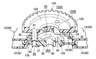
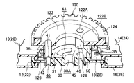
- the rotational position defining member 120 may have a shape as shown in FIGS. 18 to 21, for example. That is, on the lower surface of the main body portion 122 of the rotation position defining member 120 and in the middle between the guide tube portions 126, the claw portions 128 as the locking portions extending downward are integrated (that is, three at regular intervals). ), And the claw portions 128 may be inserted into the long hole portions 43 formed in the reinforcing portions 18 and 28 and may be locked to the annular lower surface portion 18B as shown in FIG.
- the reinforcing portions 18 and 28 can be sandwiched between the lower end portion of the guide tube portion 126 and the claw portion 128 from the vertical direction. Even if not, the reels 10 and 20 can be held directly. Therefore, in this case, the reels 10 and 20 can be directly incorporated into the drive device 60 by gripping the outer peripheral portion of the main body portion 122 of the rotational position defining member 120 with fingers or a gripping mechanism.
- the screw 38 for fastening the reinforcing portions 18 and 28 of the reel hubs 12 and 22 to the rotational member 64 of the drive device 60 is provided with the boss portion 41 ( The screw hole portion 40) and the screw boss portion 66 can be reliably and easily guided. Therefore, the pair of reels 10 and 20 are excellent in assemblability. Moreover, since the rotational position defining member 120 can be reused, it is preferable for the environment.
- the lower cartridge 106 is not limited to a configuration in which the lower cartridge 106 is completely removed from the upper cartridge 104, and may be configured to be slid and stored in the upper cartridge 104.
- the tape guide 132 as the temporary guide is not limited to a configuration in which a plurality of cylindrical guides are provided.
- a plurality of wall guides (plates) formed in a substantially arc shape in plan view are provided. You may make it the structure etc. which are provided.
- a concave portion 48 is formed in the rotating member 64, and convex portions 68 are formed in the reinforcing portions 18 and 28 of the reel hubs 12 and 22, respectively, for positioning in the circumferential direction (positions of the screw hole portion 40 and the screw boss portion 66). May be matched).
- the number of the concave portions 48 (the convex portions 68) and the screw hole portions 40 (the screw boss portions 66) is not limited to three.
- the projecting portion 42 is not limited to the one formed on the lower surface of the screw hole portion 40 and coaxially therewith, but on the concentric circumference different from the screw hole portion 40 on the lower surface of the reinforcing portions 18 and 28. It may be formed.
- the engaged portion is not limited to the illustrated reference hole 107A, and the engaging portion is not limited to the illustrated positioning pin 74.
- the reels 10 and 20 may be accommodated (held) in the magazine 100 in a state where the recording tape T is wound around each of the reels 10 and 20 and they are not connected.
Landscapes
- Storage Of Web-Like Or Filamentary Materials (AREA)
Abstract
記録テープTが外周面に巻回されるリールハブ(12)を備えたリール(10)をドライブ装置(60)へ組み込み、ドライブ装置(60)の回転部材(64)にリールハブ(12)をビス止めするときに使用される締結補助具(120)であって、本体部(122)と、本体部(122)に形成された複数のガイド孔部(122A)と同軸になるように本体部(122)の下面に突設され、ビス(38)をリールハブ(12)に形成されたビス孔部(40)へ案内するガイド筒部(126)と、ガイド筒部(126)の下端部に形成され、リールハブ(12)のビス孔部(40)の周囲に形成された被嵌合部(41A)に嵌合させる嵌合部(126A)と、を備える。ドライブ装置に組み込まれるリールのドライブ装置への組込性が確保できる。
Description
本発明は、ドライブ装置にリールを組み込むときに使用する締結補助具と、そのリールの締結方法及び締結補助具を備えたリールアセンブリに関する。
従来から、主にコンピューター等の情報記録再生媒体(データバックアップ)として使用される磁気テープ等の記録テープをリールに巻装し、そのリールをケース内に単一で収容してなる記録テープカートリッジが知られている(例えば、特開2010-79989号公報参照)。
この記録テープカートリッジは、ドライブ装置に装填されると、リールから記録テープが引き出され、ドライブ装置の巻取リールに巻き取られる。そして、ドライブ装置の記録再生ヘッドによって、その記録テープに対して情報の書き込み又は読み取りが行われるようになっている。
しかしながら、このようなシステムでは、記録テープカートリッジがドライブ装置に対してリムーバブルであるため、記録テープカートリッジ(記録テープに記録されている情報)に対してセキュリティ対策が必要となる。そのため、ドライブ装置内に直接リールを設け、そのリールが取り出されないようにすることが考えられたが、この場合、リールのドライブ装置に対する組込性を確保する必要がある。
そこで、本発明は、上記事情に鑑み、ドライブ装置に組み込まれるリールのドライブ装置への組込性を確保できる締結補助具と、そのリール締結方法及びリールアセンブリを得ることを目的とする。
上記の目的を達成するために、本発明の第1の態様の締結補助具は、記録テープが外周面に巻回されるリールハブを備えたリールをドライブ装置へ組み込み、該ドライブ装置の回転部材に前記リールハブをビス止めするときに使用される締結補助具であって、本体部と、前記本体部に形成された複数のガイド孔部と同軸になるように該本体部の下面に突設され、前記ビスを前記リールハブに形成されたビス孔部へ案内するガイド筒部と、前記ガイド筒部の下端部に形成され、前記リールハブの前記ビス孔部の周囲に形成された被嵌合部に嵌合させる嵌合部と、を有することを特徴としている。
上記第1の態様の締結補助具によれば、リールハブのビス孔部の周囲に形成された被嵌合部に、ガイド筒部の嵌合部を嵌合させることにより、ガイド孔部とビス孔部とを一致させることができる。したがって、そのガイド筒部により、リールハブのビス孔部にビスを案内することができる。これにより、ドライブ装置に組み込まれるリールのドライブ装置への組込性を確保することができる。
また、本発明の第2の態様の締結補助具は、上記第1の態様の締結補助具であって、前記本体部には、前記リールハブに形成された貫通孔に挿通され、該リールハブの下面に係止される係止部が形成されていることを特徴としている。
上記第2の態様によれば、締結補助具によってリールを支持できる。つまり、この締結補助具を把持することにより、リールをドライブ装置へ搬送することができる。したがって、ドライブ装置に組み込まれるリールのドライブ装置への組込性を確保することができる。
また、本発明の第3の態様のリールの締結方法は、記録テープが外周面に巻回されるリールハブを備えたリールをドライブ装置へ組み込み、本発明の第1の態様の締結補助具を使用して、該ドライブ装置の回転部材に前記リールハブをビス止めするリールの締結方法であって、前記リールハブの前記ビス孔部の周囲に形成された前記被嵌合部に、前記ガイド筒部の前記嵌合部を嵌合させる嵌合工程と、前記本体部の前記ガイド孔部にビスを挿入し、前記ガイド筒部を通して、前記リールハブの前記ビス孔部及び前記回転部材に形成されたビスボス部に前記ビスを供給する供給工程と、前記ビスボス部に供給された前記ビスを、前記本体部の前記ガイド孔部から挿入された工具によって該ビスボス部に螺合する螺合工程と、前記ビスを前記ビスボス部に螺合した後、前記締結補助具を前記リールハブから除去する除去工程と、を含むことを特徴としている。
上記本発明の第3の態様によれば、リールハブのビス孔部の周囲に形成された被嵌合部に、ガイド筒部の嵌合部を嵌合させることにより、ガイド孔部とビス孔部とを一致させることができる。したがって、そのガイド筒部により、リールハブのビス孔部及び回転部材のビスボス部にビスを案内することができる。これにより、ドライブ装置に組み込まれるリールのドライブ装置への組込性を確保することができる。
また、本発明の第4の態様のリールアセンブリは、ドライブ装置の回転部材の上面側に形成された複数の凸部及び凹部の何れか一方と嵌合する複数の凸部及び凹部の何れか他方がリールハブの下面側に形成され、前記凸部と前記凹部とを嵌合させることにより、前記回転部材のビスボス部に対して前記リールハブのビス孔部を一致させるように構成されたリールと、前記嵌合部を前記被嵌合部に嵌合させることで、前記リールを回転可能に保持する第1の態様又は第2の態様の締結補助具と、を有することを特徴としている。
本発明の第4の態様によれば、リールハブのビス孔部の周囲に形成された被嵌合部に、ガイド筒部の嵌合部を嵌合させることにより、リールが締結補助具に回転可能に保持される。したがって、この締結補助具でリールの周方向の位置を調整することにより、凸部と凹部とを嵌合させることができる。また、これに伴い、ガイド孔部とビス孔部とビスボス部とが一致するため、ガイド筒部により、リールハブのビス孔部及び回転部材のビスボス部にビスを案内することができる。これにより、ドライブ装置に組み込まれるリールのドライブ装置への組込性を確保することができる。
以上のように、本発明によれば、ドライブ装置に組み込まれるリールのドライブ装置への組込性を確保できる締結補助具と、そのリール締結方法及びリールアセンブリを提供することができる。
以下、本発明に係る実施の形態について、図面を基に詳細に説明する。なお、説明の便宜上、図1における矢印UPを上方向、矢印DOを下方向とし、本実施形態に係るリール10、20の回転軸方向を上下方向(高さ方向)とする。
本実施形態に係るリール10、20は、例えばポリカーボネート(PC)等の合成樹脂製とされており、図1で示すように、ドライブ装置60の筐体61(図1では底板61Aと3本の支柱61Bのみが示されている)内に一対で設けられている。
すなわち、リール10は、後述する記録テープTの繰り出し用とされ、リール20は、後述する記録テープTの巻き取り用とされており、リール10から繰り出された記録テープTが、リール20に巻き取られつつ、記録再生ヘッド70に摺接するようになっている。つまり、この記録再生ヘッド70によって、その記録テープTに対してデータが記録されたり、その記録テープTに記録されたデータが再生されたりするようになっている。
なお、記録再生ヘッド70の両側における底板61Aには、複数個(図示のものは2個ずつで計4個)のテープガイド(本ガイド)72が回転自在に設けられており、リール10から引き出され、リール20に巻き取られる記録テープTが、各テープガイド72によって、ガイドされるようになっている。
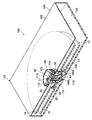
ここで、そのドライブ装置60へ一対のリール10、20を組み込むためのマガジン100について説明する。図2、図3で示すように、このマガジン100は、下方側が開放された(天壁105の周縁部に側壁が一体に立設された)略矩形箱状の上カートリッジ104と、上カートリッジ104の開放された下方側を閉塞可能な平板状の下カートリッジ106とからなるカートリッジ102を有している。
なお、上カートリッジ104及び下カートリッジ106の材質は特に限定されない。例えば、板金等の金属材料で成形してもよいし、リール10、20と同じPC等の合成樹脂材料で成形してもよい。また、下カートリッジ106を上カートリッジ104に取り外し可能に設ける構成は、任意の構成を採用して構わない。
例えば、上カートリッジ104の側壁の下端部に溝部(図示省略)を形成し、その溝部内に下カートリッジ106の互いに対向する辺縁部を進入させてスライドさせることにより、上カートリッジ104に対して下カートリッジ106を装着可能にするなどの構成を採用すればよい。そして、このマガジン100のカートリッジ102内には、後述する一対のリール10、20が、カートリッジ102の長手方向に並んで収容されている。
このマガジン100には、カートリッジ102内に収容されたリール10、20の上下方向(高さ方向)の位置を規定する樹脂製の上下位置規定部材110と、周方向(回転方向)の位置を規定する締結補助具としての樹脂製の回転位置規定部材120と、搬送時等において(ドライブ装置60に組み込まれるまで)、回転位置規定部材120(リール10、20)の回転をロックする樹脂製のロック部材130と、が備えられている。そして、これら上下位置規定部材110、回転位置規定部材120、ロック部材130により、各リール10、20を保持するリール保持手段90が構成されている。
図2、図3で示すように、上カートリッジ104の天壁105には、リール10、20毎に回転位置規定部材120及び上下位置規定部材110等を挿通させるための円形状の開口部105Aが一対で形成されている。そして、上カートリッジ104の天壁105には、ロック部材130の後述する複数本(図示のものは4本)のテープガイド132を挿通させるための長孔部105Bが、リール10、20の並び方向(カートリッジ102の長手方向)と直交する方向を長手方向として同数(図示のものは4つ)、カートリッジ102の長手方向に並んで形成されている。
なお、マガジン100の上カートリッジ104には、図1、図10A、10Bで示すように、ドライブ装置60の複数(例えば2個)の位置決めピン(係合部)74に挿通させる複数(例えば2個)の基準孔(被係合部)107Aを有する底面部107が形成されており、この底面部107と下カートリッジ106とで、カートリッジ102の底壁を構成するようになっている。そして、これにより、ドライブ装置60に対するマガジン100の配設位置が規定される(位置決めされる)ようになっている。
また、図3で示すように、マガジン100の下カートリッジ106には、各リール10、20の補強部18、28を下方から支持する環状の支持台108Aと、その支持台108A内における各リール10、20の回転中心位置に、後述する固定ビス37が螺合される円筒状のビスボス部108Bと、を有するベース部108が一体に形成されている。
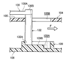
そして、この下カートリッジ106には、図8A、8Bで詳細に示すように、テープガイド132の外径よりも若干小径とされ、その下端部132Aが圧入されることでロック部材130を移動不能にロックする円形状のロック穴109Aと、ロック穴109Aと同径で連続して形成され、テープガイド132が長孔部105Bに沿って移動する際に、そのテープガイド132の下端部132Aをガイドする略楕円形状のガイド溝109Bと、を有するガイドロック部109が一体に形成されている。
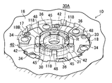
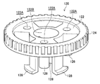
また、図4、図5で示すように、回転位置規定部材120は、外径が開口部105Aよりも大径とされ、外周部の全周に亘って係合ギア124が形成された円板状の本体部122と、本体部122の同心円周上に等間隔に複数(例えば3個)形成されたガイド孔部122Aと同軸になるように、本体部122の下面に突設された円筒状のガイド筒部126と、を有している。
各ガイド筒部126の下端部の径方向外側には、補強部18、28の後述するボス部41の外周面(被嵌合部)41Aに嵌合する嵌合部としての底面視半円弧状の延設部126Aが形成されている。つまり、延設部126Aよりも径方向内側のガイド筒部126の下端面126Bが、ボス部41の上面に当接するようになっており、延設部126Aがボス部41の外周面41Aを被覆するようになっている。そして、本体部122の中心部には、上下位置規定部材110を挿通させるための貫通孔122Bが形成されている。
また、図5で示すように、上下位置規定部材110は、外径が回転位置規定部材120の本体部122よりも小径(開口部105Aと略同径)とされた円板状の本体部112と、本体部112の中心位置に形成されたビス孔部112Aと同軸になるように、本体部112の下面に突設された円筒状のボス部114と、本体部112の下面で、かつ本体部112の同心円周上に等間隔に複数(例えば3個)突設された係止部116と、を有している。
各係止部116の下端部には、周方向で、かつ一方向に延在するフック部118が一体に形成されている。そして、このフック部118を備えた係止部116及びボス部114が、回転位置規定部材120の貫通孔122Bに挿通されるとともに、補強部18、28にそれぞれ形成されている複数(この場合は等間隔に3個)の円弧状の長孔部(貫通孔)43及び孔部30Aに、それぞれ挿通されるようになっている。
ここで、各長孔部43に挿通された各係止部116のフック部118は、図6A、6Bで示すように、フック部118の延在している一方向(図6Aで示す矢印R方向)に、後述する連結部45の周方向を向く側面に係止部116が当接するまで回転されることで、その連結部45の下面に係止されるようになっている。
これにより、図4で示すように、各上下位置規定部材110が、各リール10、20の補強部18、28との間に各回転位置規定部材120を挟んだ状態で、各リール10、20に取り付けられ(固定され)、各リール10、20が、開口部105Aよりも大径とされた本体部122を備えた回転位置規定部材120によって、上カートリッジ104の天壁105に吊下された状態に保持される構成である。
そして、この状態で、固定ビス37が上下位置規定部材110の本体部112における中心位置に形成されたビス孔部112Aに挿通され、下カートリッジ106のベース部108におけるビスボス部108Bに螺合されることにより、上カートリッジ104と下カートリッジ106とが接合され、カートリッジ102内において、各リール10、20が上下方向の位置を規定された状態で収容されるようになっている。
つまり、これにより、各リール10、20が、上下位置規定部材110及び回転位置規定部材120によって上カートリッジ104に位置決め保持されるだけではなく、下カートリッジ106のベース部108(支持台108A)によって下方から支持され、マガジン100(カートリッジ102)内において、各上フランジ14、24が上カートリッジ104の天壁105の内面に非接触となり、かつ、各下フランジ16、26が下カートリッジ106の内面に非接触となる構成である。
ここで、リール10、20について、主に図5、図6A、6Bを基に説明する。マガジン100に収容され、そのマガジン100からドライブ装置60へ供給される繰り出し用リール10は、軸心部を構成する略円筒状のリールハブ12と、その上端部側に設けられる環状の上フランジ14と、その下端部側に設けられる環状の下フランジ16と、リールハブ12の内周面における高さ(軸)方向略中央部に一体に連設された補強部18と、を含んで構成されている。
同様に、マガジン100に収容され、そのマガジン100からドライブ装置60へ供給される巻き取り用リール20も、軸心部を構成する略円筒状のリールハブ22と、その上端部側に設けられる環状の上フランジ24と、その下端部側に設けられる環状の下フランジ26と、リールハブ22の内周面における高さ(軸)方向略中央部に一体に連設された補強部28と、を含んで構成されている。
そして、リール10におけるリールハブ12の外周面には、情報記録再生媒体としての磁気テープ等の記録テープTが巻回されるようになっており、上フランジ14及び下フランジ16によって、巻回された記録テープTの幅方向の端部が保持されるようになっている。そして更に、リール10から繰り出された記録テープTは、リール20におけるリールハブ22の外周面に巻回され、上フランジ24及び下フランジ26によって、その幅方向の端部が保持されるようになっている。
なお、本実施形態における「略円筒状」には、記録テープTが巻回される各リールハブ12、22の外周面(巻面)の形状が太鼓形状等に形成されている概ね円柱状であるもの、及び各リールハブ12、22の内周面側にリブ等が突設されている完全な円筒状でない中空状であるものなども含まれる。
また、以下においては、リール20はリール10と同一の構成であるため、主にリール10について説明する。図5、図6A、6Bで示すように、上フランジ14の内周縁部には、下方へ所定高さ延在する円筒部15が一体に形成されており、下フランジ16の内周縁部には、上方へ所定高さ延在する円筒部17が一体に形成されている。
円筒部15の内周面及び円筒部17の内周面には、それぞれ径方向内側(リール10の回転中心部)に向かって突出する平板状の張出部32、34が等間隔に複数個(例えば6個ずつ)、平面視で互いに重ならない位置に形成されており、各張出部32、34には、それぞれ円形状の孔部(図示省略)が形成されている。
また、リールハブ12の補強部18における外周縁部側(リールハブ12の内周面側)の下面及び上面には、内周面に雌ネジが切られた円筒状のビスボス部33、35が、それぞれ等間隔に複数個(例えば6個ずつ)、平面視で互いに重ならない位置に突設されている。そして、各ビスボス部33、35と各張出部32、34の孔部とが互いに連通されるようになっている。
したがって、上方から上フランジ14の張出部32の孔部に挿入されたビス36がビスボス部33に螺合され、下方から下フランジ16の張出部34の孔部に挿入されたビス36がビスボス部35に螺合されることにより、上フランジ14及び下フランジ16が、それぞれリールハブ12に一体的に取り付けられるようになっている。
また、円筒部15及び円筒部17よりも径方向内側における補強部18の中心部分には、小円筒部30と、小円筒部30よりも大径とされた大円筒部31とが設けられており、小円筒部30の外周面と大円筒部31の内周面とが、等間隔に3箇所設けられた連結部45によって一体に連結されて構成されている。
そして、大円筒部31の上面が、側面視で上フランジ14の上面から突出しない程度に上方へ向かって突出された環状上面部18Aとされ、大円筒部31の下面が、側面視で下フランジ16の下面から突出しない程度に下方へ向かって突出された環状下面部18Bとされている。
なお、小円筒部30の孔部30Aに、ドライブ装置60の後述する軸出部62(図7参照)が挿入(嵌合)されるようになっている。また、小円筒部30と大円筒部31とは、補強部18の上面及び下面において同じ高さに形成されており、連結部45は、補強部18の上面側では小円筒部30及び大円筒部31と同じ高さに形成されている。
すなわち、この連結部45は、補強部18の下面側では小円筒部30及び大円筒部31よりも低い高さに形成されており、その下面に係止されるフック部118が環状下面部18Bと略面一になる(下カートリッジ106を上カートリッジ104に接合したときに、フック部118が支持台108Aを相対的に押圧しない)ように構成されている。
また、補強部18の下面側で、かつ各連結部45の径方向外側には、側面視で環状下面部18Bよりも下方へ突出する円筒状の突出部(ボス部)42が等間隔に3個形成され、補強部18の上面側で、かつ各連結部45の径方向外側には、側面視で環状上面部18Aよりも高さの低い円筒状のボス部41が等間隔に3個形成されている。そして、このボス部41(突出部42)が、ドライブ装置60の後述する回転部材64に補強部18を固定するためのビス38(図11A、11B、図14参照)が挿通されるビス孔部40を構成している。
また、補強部18の上面側において、各ボス部41の高さは、各延設部126Aの高さ(下端面126Bからの突出高さ)と略同一とされており、各延設部126Aが、環状上面部18Aよりも径方向外側に張り出すボス部41の外周面41Aに嵌合することにより、回転位置規定部材120が、リール10の補強部18に対して回り止めされ、そのリール10と一体に回転可能とされている。
つまり、この回転位置規定部材120が、ロック部材130によって、その回転が規制されることで、リール10の不用意な回転が阻止されるようになっている。そして、この回転位置規定部材120のガイド筒部126は、ドライブ装置60の回転部材64へリール10、20の補強部18、28を取り付けるときに、そのリール固定用のビス38を補強部18、28のボス部41(ビス孔部40)及び回転部材64の後述するビスボス部66へ案内するガイド手段になっている。
また、図7で示すように、リール10の補強部18の下面で、かつ突出部42(ビス孔部40)同士の中間には、ドライブ装置60の回転部材64に突設された凸部68が嵌合される凹部48がそれぞれ形成されている(即ち、この凹部48は等間隔に3個形成されている)。なお、この凹部48は、径方向外側へ向けて開口するように形成されている。
一方、ドライブ装置60には、駆動源としてのモーター(図示省略)が配置されており、そのモーターの回転軸(図示省略)から伝達ギア(図示省略)を介して回転駆動力が伝達される一対の樹脂製又は金属製の回転部材64(図7参照)が、ドライブ装置60の筐体61(底板61A)に形成された一対の開口部58(図10A、10B、図11A、11B参照)内にそれぞれ回転可能に設けられている。
各回転部材64には、各リール10、20におけるリールハブ12、22の補強部18、28が、ビス38によって固定されるようになっている。すなわち、各回転部材64の同心円周上には、各補強部18、28のビス孔部40に挿入されたビス38が螺合されるビスボス部66が等間隔に3個形成されている。
そして、各リールハブ12、22の補強部18、28に形成された凹部48に嵌合する凸部68が、各回転部材64のビスボス部66同士の中間に配置されるように、等間隔に3個突設されている。そして更に、各回転部材64の中央部(回転中心部)には、補強部18、28(小円筒部30)の孔部30Aに挿入される円柱状の軸出部62が上方に向かって突設されている。
したがって、記録テープTが巻回されたリール10と、記録テープTの自由端側がリールハブ22の外周面に取り付けられたリール20を、ドライブ装置60の各回転部材64に固定するときには、各軸出部62が各孔部30Aに挿入される。そして、各凹部48に各凸部68が嵌合されることにより、各ビス孔部40と各ビスボス部66との位置が一致され、上方からビス38が各ビス孔部40に挿入されて、各ビスボス部66に螺合されることにより、各リールハブ12、22と各回転部材64とが一体的に固定される。
次に、ロック部材130について説明する。このロック部材130は、図2で示すように、平面視略「Ω」字状に形成されており、その円弧状に形成された中央部130Aの先端部130Bの下面には、仮ガイドとしての円柱状のテープガイド132が複数本(図示のものは4本)、その円弧形状に沿って並ぶように一体に突設されている。そして、図9A、9Bで詳細に示すように、ロック部材130の両端部130Cには、回転位置規定部材120の係合ギア124と噛合するロックギア134が形成されている。
ここで、このロック部材130は、テープガイド132が上カートリッジ104の天壁105に形成された複数の長孔部105Bに外部から挿通されることにより、その上カートリッジ104の天壁105の外面に取り付けられるようになっている。すなわち、テープガイド132を長孔部105Bへ挿通させたロック部材130を、図2、図8Aで示す矢印F方向にスライドさせる。
すると、テープガイド132の下端部132Aは、図8Aで示すように、ガイド溝109Bによって矢印F方向にガイドされ、その下端部132Aがガイド溝109Bの先端部に当接したときに、図9Aで示すように、ロックギア134が係合ギア124に噛合するようになっている。そして、図8Bで示すように、ロック部材130の中央部130Aの肉厚とされた先端部130Bを下方に向けて(矢印G方向へ)上方から押圧し、テープガイド132の下端部132Aをロック穴109Aに圧入(嵌合)させる。
これにより、ロック部材130が、上カートリッジ104の天壁105に固定配置される構成であり、マガジン100がドライブ装置60に組み込まれるまで、各リール10、20の不用意な回転が阻止される(ロックされる)構成である。そして、図2で示すように、リール10から繰り出され、リール20のリールハブ22の外周面に巻回された記録テープTが、テープガイド132によってある程度の張力が付与された状態で保持される構成である。
なお、マガジン100内のリール10、20をドライブ装置60に組み込むために、ロック部材130による回転ロックを解除する際には、まず、ロック部材130の先端部130Bを上方へ引き上げ、ロック穴109Aからテープガイド132の下端部132Aを外す。そして、ロック部材130(テープガイド132)を長孔部105Bに沿って図2、図8Aで示す矢印F方向とは反対方向(図13で示す矢印E方向)にスライドさせ、図9Bで示すように、係合ギア124からロックギア134を外せばよい。
次に、このようなマガジン100を使用した場合のドライブ装置60へのリール10、20の組込方法(回転位置規定部材120を使用したリール10、20の締結方法)について説明する。記録テープTが巻回されたリール10と、記録テープTの自由端側がリールハブ22に取り付けられたリール20は、リール保持手段90により、上カートリッジ104に保持され、固定ビス37により下カートリッジ106が上カートリッジ104に接合されることで、カートリッジ102内に収容されている。
すなわち、各リール10、20における補強部18、28の各ボス部41の外周面41Aに、回転位置規定部材120の各ガイド筒部126の延設部126Aが嵌合し(嵌合工程)、上下位置規定部材110により、各回転位置規定部材120が各リール10、20に固定されるとともに、ロック部材130により回転位置規定部材120の回転がロックされることにより、各リール10、20が回転不能に保持されている。
そして、その状態で、上フランジ14、24及び下フランジ16、26が、上カートリッジ104及び下カートリッジ106の内面に非接触とされている。したがって、マガジン100の搬送時等において、そのマガジン100に衝撃が加わっても、マガジン100内に収容されている特にリール10の上フランジ14及び下フランジ16の変形が抑制又は防止される。よって、リール10に巻回されている記録テープTの幅方向両端部(エッジ)にダメージが発生し難い。
さて、このマガジン100をドライブ装置60へ組み込むときには、まず、図10A,図10Bで示すように、下カートリッジ106を取り外す。すなわち、上下位置規定部材110の本体部112における中心位置に螺合されている固定ビス37を取り外す。
そして、ロック部材130の先端部130B側を上方へ引き上げ、ロック穴109Aからテープガイド132の下端部132Aを外す。これにより、下カートリッジ106が上カートリッジ104から取り外される。なお、ロック穴109Aからテープガイド132の下端部132Aを外した後、固定ビス37を取り外すようにしてもよい。
下カートリッジ106を上カートリッジ104から取り外したら、その上カートリッジ104を筐体61の底板61A上へ移動させ、その底板61A上に突設されている位置決めピン74を、上カートリッジ104の底面部107に形成された基準孔107Aに挿通させる。
これにより、ドライブ装置60の各回転部材64に対して、各リール10、20が位置決めされる。すなわち、各リール10、20におけるリールハブ12、22の補強部18、28が、ドライブ装置60の各回転部材64の上に位置決めされて配置される。この状態を図10B及び図12で示す。
なお、このとき、ロック部材130のテープガイド132は、ドライブ装置60の各テープガイド72の間で、かつ各テープガイド72よりも記録再生ヘッド70から離れる方向側(矢印F方向側)に配置されているため、そのテープガイド72に干渉しない(図12参照)。したがって、各リール10、20を保持している上カートリッジ104を、ドライブ装置60の筐体61の底板61A上へ位置決めして配置することが容易にできる。
その後、図13で示すように、ロック部材130のテープガイド132を長孔部105Bに沿って矢印F方向とは反対方向である矢印E方向へスライドさせる(記録テープTから退避させる)。つまり、図9A、9Bで示したように、回転位置規定部材120の係合ギア124からロック部材130のロックギア134を外し、回転位置規定部材120の回転ロックを解除する。そして、ロック部材130を上カートリッジ104から取り除く。
一方、各リールハブ12、22の補強部18、28が、各回転部材64の上に配置されると、各回転部材64の軸出部62が各補強部18、28(小円筒部30)の孔部30Aに挿入され、各回転部材64に対する各リールハブ12、22(補強部18、28)の径方向の位置が精度良く位置決めされる(センタリングされる)。そして、各回転部材64の複数(ビスボス部66と同数)の凸部68が、各リールハブ12、22の補強部18、28に形成された複数(ビス孔部40と同数)の凹部48に嵌合される。
したがって、各回転部材64に対する各リールハブ12、22(補強部18、28)の周方向の位置(回転角度)が精度良く位置決めされ、各リールハブ12、22の補強部18、28におけるボス部41(ビス孔部40)と、各回転部材64におけるビスボス部66との位置が一致される。なお、このとき、回転位置規定部材120を手動で回転させることにより、リール10、20を僅かに回転させ(リール10、20の周方向の位置を調整し)、凹部48に凸部68を嵌合させるように誘導してもよい。
すなわち、上カートリッジ104からロック部材130を取り除くと、テープガイド132は、ドライブ装置60のテープガイド72よりも記録再生ヘッド70から離れる方向側(矢印F方向側)に配置されているので、記録テープTは僅かに弛んだ状態となっている。そのため、回転位置規定部材120を僅かに回転させることが可能となっている。しかも、回転位置規定部材120の外周部には、係合ギア124が形成されているので、回転位置規定部材120を手指で回転させるときに、手指が滑り難く回転させ易い。
また、リール10、20を僅かに回転させることなく、凹部48に凸部68を嵌合させることができた場合でも、上記のように記録テープTは僅かに弛んだ状態となっているため、リール10、20を僅かに回転させ、記録テープTをテープガイド72に沿わせる。これにより、テープガイド132にガイドされていた記録テープTを、テープガイド72にスムーズに受け渡すことができる(各リール10、20のドライブ装置60への組み付け時に記録テープTを容易にパスさせることができる)。
こうして、回転部材64に対するリールハブ12、22の補強部18、28の位置が規定されたら、上下位置規定部材110を矢印R方向とは反対方向に回転させて連結部45に対するフック部118の係止を解除し、図11Aで示すように、上カートリッジ104(回転位置規定部材120)から、その上下位置規定部材110を取り外す。
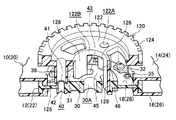
そして、図14、図15で示すように、回転位置規定部材120のガイド孔部122Aにビス38を挿入することにより(供給工程)、ボス部41のビス孔部40にビス38を挿通し、次いで、図示しない工具をガイド孔部122Aに挿入し、そのビス38をビスボス部66に螺合する(螺合工程)。
すなわち、このときには、各リール10、20の補強部18、28に設けられたボス部41(ビス孔部40)と回転部材64のビスボス部66とが連通(一致)し、回転位置規定部材120のガイド筒部126の延設部126Aが、ボス部41の外周面41Aに嵌合していることにより、ガイド孔部122Aとビス孔部40とが連通(一致)している。
したがって、各ガイド筒部126のガイド孔部122Aに、それぞれビス38を挿入することにより、確実かつ容易に各ボス部41のビス孔部40に各ビス38を挿通することができ、各ビス38を各ビスボス部66に螺合することができる。
これにより、一方の回転部材64にリールハブ12の補強部18を固定することができ、他方の回転部材64にリールハブ22の補強部28を固定することができる。なお、リール固定用のビス38の形状は、図11Aで示す形状であってもよいし、図14、図15で示す形状であってもよい。
また、このとき、各リールハブ12、22の補強部18、28の下面に形成されている突出部42が回転部材64の上面に当接するので、各リール10、20(各リールハブ12、22の補強部18、28)は、各回転部材64に対して、その高さ(軸)方向の位置が精度良く位置決めされて固定される。
こうして、各リール10、20の補強部18、28を各回転部材64に固定したら、図11Bで示すように、回転位置規定部材120と上カートリッジ104をドライブ装置60の筐体61内(底板61A上)から取り除く(除去工程)。なお、回転位置規定部材120を上カートリッジ104から取り除いた後、上カートリッジ104を筐体61内(底板61A上)から取り除くようにしてもよい。
本実施形態に係る回転位置規定部材120は、以上のような構成であるが、この回転位置規定部材120の形状は、図5、図14、図15で示した形状に限定されるものではなく、例えば図16、図17で示すような形状(図16、図17では上カートリッジ104を省略している)とされてもよい。
すなわち、例えば図16で示すように、ガイド筒部126の下端部に延設部126Aを形成せず、その下端部の径方向内側部分を、ボス部41を形成することによって補強部18、28の大円筒部31の外周部に設けられた被嵌合部としての円弧状の切欠壁面46(図14も参照)に嵌合させる構成とされた回転位置規定部材120としてもよい。
また、例えば図17で示すように、ガイド筒部126同士を一体に連結するとともに大円筒部31の外周面に嵌合可能な内径とされた円弧状壁部50を、回転位置規定部材120の本体部122の下面に一体に形成し、ガイド筒部126の下端部における径方向内側部分を切欠壁面46に嵌合させるとともに、円弧状壁部50の内周面を大円筒部31の外周面(被嵌合部)に嵌合させる構成とされた回転位置規定部材120としてもよい。
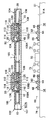
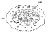
また、本実施形態に係る回転位置規定部材120は、例えば図18~図21で示すような形状としてもよい。すなわち、回転位置規定部材120の本体部122の下面で、かつ各ガイド筒部126同士の中間に、下方へ延在する係止部としての爪部128を一体に(即ち、等間隔に3個)形成し、各爪部128を補強部18、28に形成された各長孔部43に挿通させるとともに、図21で示すように、環状下面部18Bに係止させる構成にしてもよい。
このような構成の回転位置規定部材120にすると、ガイド筒部126の下端部と爪部128とで補強部18、28を上下方向から狭持することができるので、上下位置規定部材110を使用しなくても、直接リール10、20を保持することができる。したがって、この場合は、回転位置規定部材120の本体部122の外周部を手指又は把持機構で把持することにより、各リール10、20をドライブ装置60へ直接組み込むことができる。
なお、本体部122の外周部には、係合ギア124(ギア形状)が形成されている方が滑り防止の観点から望ましいが、係合ギア124が形成されていなくてもよい。また、この回転位置規定部材120によってリール10、20をドライブ装置60に組み込んだ後は、筐体61の底板61Aとリール10、20との間に形成される隙間から取外治具(図示省略)を差し込み、環状下面部18Bに対する爪部128の係止を解除しつつ回転位置規定部材120をリール10、20から取り除けばよい。
何れにしても、本実施形態に係る回転位置規定部材120によれば、リールハブ12、22の補強部18、28をドライブ装置60の回転部材64に締結するためのビス38を、ボス部41(ビス孔部40)及びビスボス部66へ確実かつ容易に案内することができる。したがって、一対のリール10、20の組込性に優れる。しかも、この回転位置規定部材120は再使用可能であるため、環境にも好ましい。
以上、本実施形態に係る締結補助具(回転位置規定部材120)及びその締結方法並びにリールアセンブリ(回転位置規定部材120を備えたリール10、20)について図面を基に説明したが、本実施形態に係る締結補助具及びその締結方法並びにリールアセンブリは、図示のものに限定されるものではなく、本発明の要旨を逸脱しない範囲内で適宜設計変更可能なものである。
また、マガジン100において、下カートリッジ106は、上カートリッジ104から完全に取り外される構成に限定されるものではなく、スライドして上カートリッジ104内に収納される構成等にしてもよい。また、仮ガイドとしてのテープガイド132は、円柱状のものが複数個設けられる構成に限定されるものではなく、例えば平面視略円弧状に形成された壁状(板状)のものが複数個設けられる構成等にしてもよい。
更に、回転部材64に凹部48を形成し、各リールハブ12、22の補強部18、28に凸部68を形成して、周方向の位置決めをする(ビス孔部40とビスボス部66との位置を一致させる)ようにしてもよい。なお、凹部48(凸部68)及びビス孔部40(ビスボス部66)の数量も3個に限定されるものではない。
また、突出部42は、ビス孔部40の下面に、それと同軸に形成されているものに限定されるものではなく、補強部18、28の下面のビス孔部40とは異なる同心円周上に形成されていてもよい。また、被係合部は図示の基準孔107Aに限定されるものではなく、係合部も図示の位置決めピン74に限定されるものではない。また、リール10、20は、それぞれに記録テープTが巻回されていて、それらが接続されていない状態で、マガジン100内に収容(保持)されていてもよい。
Claims (4)
- 記録テープが外周面に巻回されるリールハブを備えたリールをドライブ装置へ組み込み、該ドライブ装置の回転部材に前記リールハブをビス止めするときに使用される締結補助具であって、
本体部と、
前記本体部に形成された複数のガイド孔部と同軸になるように該本体部の下面に突設され、前記ビスを前記リールハブに形成されたビス孔部へ案内するガイド筒部と、
前記ガイド筒部の下端部に形成され、前記リールハブの上面側における前記ビス孔部の周囲に形成された被嵌合部に嵌合させる嵌合部と、
を有することを特徴とする締結補助具。 - 前記本体部には、前記リールハブに形成された貫通孔に挿通され、該リールハブの下面に係止される係止部が形成されていることを特徴とする請求項1に記載の締結補助具。
- 記録テープが外周面に巻回されるリールハブを備えたリールをドライブ装置へ組み込み、請求項1に記載の締結補助具を使用して、該ドライブ装置の回転部材に前記リールハブをビス止めするリールの締結方法であって、
前記リールハブの上面側における前記ビス孔部の周囲に形成された前記被嵌合部に、前記ガイド筒部の前記嵌合部を嵌合させる嵌合工程と、
前記本体部の前記ガイド孔部にビスを挿入し、前記ガイド筒部を通して、前記リールハブの前記ビス孔部及び前記回転部材に形成されたビスボス部に前記ビスを供給する供給工程と、
前記ビスボス部に供給された前記ビスを、前記本体部の前記ガイド孔部から挿入された工具によって該ビスボス部に螺合する螺合工程と、
前記ビスを前記ビスボス部に螺合した後、前記締結補助具を前記リールハブから除去する除去工程と、
を含むことを特徴とするリールの締結方法。 - ドライブ装置の回転部材の上面側に形成された複数の凸部及び凹部の何れか一方と嵌合する複数の凸部及び凹部の何れか他方がリールハブの下面側に形成され、前記凸部と前記凹部とを嵌合させることにより、前記回転部材のビスボス部に対して前記リールハブのビス孔部を一致させるように構成されたリールと、
前記嵌合部を前記被嵌合部に嵌合させることで、前記リールを回転可能に保持する請求項1又は請求項2に記載の締結補助具と、
を有することを特徴とするリールアセンブリ。
Priority Applications (1)
| Application Number | Priority Date | Filing Date | Title |
|---|---|---|---|
| US13/948,180 US9524750B2 (en) | 2011-03-03 | 2013-07-23 | Fastening aids, method of fastening reel, and reel assembly |
Applications Claiming Priority (2)
| Application Number | Priority Date | Filing Date | Title |
|---|---|---|---|
| JP2011-046698 | 2011-03-03 | ||
| JP2011046698A JP2012185871A (ja) | 2011-03-03 | 2011-03-03 | 締結補助具及びリールの締結方法並びにリールアセンブリ |
Related Child Applications (1)
| Application Number | Title | Priority Date | Filing Date |
|---|---|---|---|
| US13/948,180 Continuation US9524750B2 (en) | 2011-03-03 | 2013-07-23 | Fastening aids, method of fastening reel, and reel assembly |
Publications (1)
| Publication Number | Publication Date |
|---|---|
| WO2012117918A1 true WO2012117918A1 (ja) | 2012-09-07 |
Family
ID=46757856
Family Applications (1)
| Application Number | Title | Priority Date | Filing Date |
|---|---|---|---|
| PCT/JP2012/054317 Ceased WO2012117918A1 (ja) | 2011-03-03 | 2012-02-22 | 締結補助具及びリールの締結方法並びにリールアセンブリ |
Country Status (3)
| Country | Link |
|---|---|
| US (1) | US9524750B2 (ja) |
| JP (1) | JP2012185871A (ja) |
| WO (1) | WO2012117918A1 (ja) |
Families Citing this family (1)
| Publication number | Priority date | Publication date | Assignee | Title |
|---|---|---|---|---|
| TWI656111B (zh) | 2015-12-31 | 2019-04-11 | Rohm And Haas Electronic Materials Llc | 光酸產生劑 |
Citations (2)
| Publication number | Priority date | Publication date | Assignee | Title |
|---|---|---|---|---|
| JP2004338043A (ja) * | 2003-05-15 | 2004-12-02 | Nec Saitama Ltd | ねじ浮き検出機構を備えたねじ締め装置 |
| JP2007226895A (ja) * | 2006-02-23 | 2007-09-06 | Mitsumi Electric Co Ltd | 記録再生装置及びそれに使用される巻取りリール |
Family Cites Families (14)
| Publication number | Priority date | Publication date | Assignee | Title |
|---|---|---|---|---|
| US2845232A (en) * | 1955-08-30 | 1958-07-29 | Leeds & Northrup Co | Chart-drive mechanism for a strip-chart recorder |
| US3000582A (en) * | 1959-08-13 | 1961-09-19 | Ampex | Tape reel hold down device |
| US3561699A (en) * | 1968-11-27 | 1971-02-09 | Minnesota Mining & Mfg | Dual hub assembly for reels |
| JPH1168383A (ja) * | 1997-08-11 | 1999-03-09 | Fuji Mach Mfg Co Ltd | テープ巻取体およびカバーテープ巻取装置 |
| US6062500A (en) * | 1998-06-01 | 2000-05-16 | Quantum Corporation | High speed reel |
| JP3441696B2 (ja) * | 1999-04-22 | 2003-09-02 | 日本サーボ株式会社 | チップマウンター用チップフィーダ |
| US6422502B1 (en) * | 2000-02-24 | 2002-07-23 | Ntn Corporation | Winding unit |
| JP3900802B2 (ja) * | 2000-07-27 | 2007-04-04 | 富士通株式会社 | ねじ締め装置 |
| JP2002358748A (ja) * | 2001-02-21 | 2002-12-13 | Fuji Photo Film Co Ltd | 記録メディアカートリッジおよび樹脂成形品 |
| JP2004039153A (ja) * | 2002-07-05 | 2004-02-05 | Fuji Photo Film Co Ltd | 記録テープカートリッジ |
| US7549602B2 (en) * | 2006-03-22 | 2009-06-23 | Hitachi Maxell, Ltd. | Tape cartridge |
| JP2007073184A (ja) * | 2006-12-04 | 2007-03-22 | Fujitsu Ltd | ディスク駆動装置のディスククランプリングのネジ締め装置 |
| JP4974990B2 (ja) | 2008-09-25 | 2012-07-11 | 富士フイルム株式会社 | 記録テープカートリッジ |
| US9087550B2 (en) * | 2012-03-20 | 2015-07-21 | Oracle International Corporation | Method for fabricating an apparatus for use in a tape drive |
-
2011
- 2011-03-03 JP JP2011046698A patent/JP2012185871A/ja active Pending
-
2012
- 2012-02-22 WO PCT/JP2012/054317 patent/WO2012117918A1/ja not_active Ceased
-
2013
- 2013-07-23 US US13/948,180 patent/US9524750B2/en active Active
Patent Citations (2)
| Publication number | Priority date | Publication date | Assignee | Title |
|---|---|---|---|---|
| JP2004338043A (ja) * | 2003-05-15 | 2004-12-02 | Nec Saitama Ltd | ねじ浮き検出機構を備えたねじ締め装置 |
| JP2007226895A (ja) * | 2006-02-23 | 2007-09-06 | Mitsumi Electric Co Ltd | 記録再生装置及びそれに使用される巻取りリール |
Also Published As
| Publication number | Publication date |
|---|---|
| US20130306778A1 (en) | 2013-11-21 |
| JP2012185871A (ja) | 2012-09-27 |
| US9524750B2 (en) | 2016-12-20 |
Similar Documents
| Publication | Publication Date | Title |
|---|---|---|
| JP5621527B2 (ja) | テープカートリッジ | |
| US7533840B2 (en) | Reel and recording tape cartridge | |
| JP3563300B2 (ja) | テープ・スレッディング装置 | |
| WO2012117918A1 (ja) | 締結補助具及びリールの締結方法並びにリールアセンブリ | |
| US7690594B2 (en) | Recording tape cartridge | |
| EP1293352B1 (en) | Ink film holding device and ink film reel | |
| JP5496932B2 (ja) | リールの組込方法及びマガジン | |
| JP2003272341A (ja) | 記録テープカートリッジ | |
| JP5570904B2 (ja) | リール | |
| JP2007301835A (ja) | 塗膜転写具 | |
| WO2016147363A1 (ja) | テープフィーダのリール保持装置 | |
| CN116728981B (zh) | 盒 | |
| JP3839741B2 (ja) | 記録テープカートリッジ | |
| JP3642938B2 (ja) | 磁気テープカートリッジ | |
| JP6256584B2 (ja) | テープカートリッジ | |
| JP2005149648A (ja) | 磁気テープカートリッジ | |
| JP6052449B2 (ja) | テープカートリッジ | |
| US7364107B2 (en) | Tape cartridge | |
| JP3613452B2 (ja) | 運行記録計の記録紙装着機構 | |
| JP2007052831A (ja) | リール及び記録テープカートリッジ | |
| JPS639884Y2 (ja) | ||
| JP2015006804A (ja) | テープリール装置 | |
| JPH11213610A (ja) | 磁気テープカートリッジ | |
| JP2007066466A (ja) | リール及び記録テープカートリッジ | |
| JP2007080326A (ja) | リール及び記録テープカートリッジ |
Legal Events
| Date | Code | Title | Description |
|---|---|---|---|
| 121 | Ep: the epo has been informed by wipo that ep was designated in this application |
Ref document number: 12752397 Country of ref document: EP Kind code of ref document: A1 |
|
| NENP | Non-entry into the national phase |
Ref country code: DE |
|
| 122 | Ep: pct application non-entry in european phase |
Ref document number: 12752397 Country of ref document: EP Kind code of ref document: A1 |