WO2012117903A1 - インプラント用紫外線照射装置 - Google Patents
インプラント用紫外線照射装置 Download PDFInfo
- Publication number
- WO2012117903A1 WO2012117903A1 PCT/JP2012/054190 JP2012054190W WO2012117903A1 WO 2012117903 A1 WO2012117903 A1 WO 2012117903A1 JP 2012054190 W JP2012054190 W JP 2012054190W WO 2012117903 A1 WO2012117903 A1 WO 2012117903A1
- Authority
- WO
- WIPO (PCT)
- Prior art keywords
- ultraviolet
- housing
- implant
- irradiation device
- connector
- Prior art date
- Legal status (The legal status is an assumption and is not a legal conclusion. Google has not performed a legal analysis and makes no representation as to the accuracy of the status listed.)
- Ceased
Links
Images



Classifications
-
- A—HUMAN NECESSITIES
- A61—MEDICAL OR VETERINARY SCIENCE; HYGIENE
- A61L—METHODS OR APPARATUS FOR STERILISING MATERIALS OR OBJECTS IN GENERAL; DISINFECTION, STERILISATION OR DEODORISATION OF AIR; CHEMICAL ASPECTS OF BANDAGES, DRESSINGS, ABSORBENT PADS OR SURGICAL ARTICLES; MATERIALS FOR BANDAGES, DRESSINGS, ABSORBENT PADS OR SURGICAL ARTICLES
- A61L2/00—Disinfection or sterilisation of materials or objects, in general; Accessories therefor
- A61L2/02—Disinfection or sterilisation of materials or objects, in general; Accessories therefor using physical processes
- A61L2/08—Radiation
- A61L2/10—Ultraviolet [UV] radiation
-
- A—HUMAN NECESSITIES
- A61—MEDICAL OR VETERINARY SCIENCE; HYGIENE
- A61C—DENTISTRY; APPARATUS OR METHODS FOR ORAL OR DENTAL HYGIENE
- A61C8/00—Means to be fixed to the jaw-bone for consolidating natural teeth or for fixing dental prostheses thereon; Dental implants; Implanting tools
-
- A—HUMAN NECESSITIES
- A61—MEDICAL OR VETERINARY SCIENCE; HYGIENE
- A61L—METHODS OR APPARATUS FOR STERILISING MATERIALS OR OBJECTS IN GENERAL; DISINFECTION, STERILISATION OR DEODORISATION OF AIR; CHEMICAL ASPECTS OF BANDAGES, DRESSINGS, ABSORBENT PADS OR SURGICAL ARTICLES; MATERIALS FOR BANDAGES, DRESSINGS, ABSORBENT PADS OR SURGICAL ARTICLES
- A61L2103/00—Materials or objects being the target of disinfection or sterilisation
- A61L2103/05—Living organisms or biological materials
Definitions
- the present invention relates to an implantable ultraviolet irradiation device that removes organic contaminants by irradiating the implant with ultraviolet rays, and more particularly to an implantable ultraviolet irradiation device that removes organic contaminants from dental implants using an ultraviolet lamp. It is related to.
- Implants especially dental implants, are implanted in the jawbone with the aim of substituting the lost tooth function, and in dental implant surgery, the dental implant can be sufficiently combined with the bone (osseointegration). It is essential. Therefore, for example, paragraph 0009 of Japanese Patent No. 3072303 (Patent Document 1) proposes to remove organic contaminants attached to the dental implant by irradiating the dental implant with ultraviolet rays. However, in this prior document, only description as an idea is made, and a specific device structure that realizes this is not proposed.
- the implant cannot be sufficiently treated with ultraviolet light, so the illuminance of the ultraviolet lamp needs to be monitored.
- the ultraviolet irradiation device ozone is generated inside the device by the irradiation of ultraviolet rays, and the object to be treated is cleaned by the ozone and ultraviolet rays. Therefore, the housing needs to be sealed and irradiated with ultraviolet rays.
- the illuminance meter (ultraviolet sensor) receives the ultraviolet ray and converts it into an electrical signal, and the electrical signal from the light receiving unit is the main body. And a main body for receiving the electrical signal and displaying the amount of light and operating the device.
- the light receiving unit must be disposed in the vicinity of the ultraviolet lamp in the housing, while the main body unit must be disposed outside the housing for checking illuminance and various operations. For this reason, it is necessary to electrically connect a light-receiving part and a main-body part in the boundary of sealed space. If such an illuminance meter (ultraviolet sensor) is to be used as it is, the light receiving part will be out of the casing and the main body will be out of the casing, and the sealed casing will not be in a sealed state.
- illuminance meter ultraviolet sensor
- the light receiving portion of the illuminometer deteriorates when the ultraviolet ray is continuously measured
- a connector capable of detaching the light receiving portion is provided inside the sealed space.
- a resin is used for insulation in the connector, and when the resin is exposed to the atmosphere in the processing chamber, there is a problem that the connector deteriorates and causes a failure of the connector.
- the present situation is that an ultraviolet irradiation device for implants that takes into consideration the viewpoint of safely and reliably monitoring the illuminance of the ultraviolet lamp while ensuring a sealed structure of the housing is expected.
- the problem to be solved by the present invention is to monitor the illuminance of an ultraviolet lamp in an implantable ultraviolet irradiation apparatus for removing organic contaminants of an implant such as an artificial tooth root using an ultraviolet lamp that emits ultraviolet rays. It is an object to provide a structure of an ultraviolet irradiation device for an implant which prevents the deterioration by inserting a light receiving portion into the housing every time it is monitored while maintaining the sealed structure of the housing.
- an ultraviolet irradiation device for an implant includes an ultraviolet lamp disposed inside a housing and an implant holder for holding the implant, and the implant is placed in the housing.
- a carriage that can be pulled out to carry the holder in and out, and a cable to the light receiving portion of the ultraviolet sensor is detachably connected to the wall of the casing inside the casing, and the ultraviolet sensor is outside the casing.
- a connector for detachably connecting a cable to the main body portion is provided, and a partition wall for shielding ultraviolet rays is provided between the connector and the ultraviolet lamp.
- the partition wall divides the housing into a processing chamber in which an ultraviolet lamp is accommodated and an ozone processing chamber in which ozone removing means is disposed, and the connector is disposed on the ozone processing chamber side. It is characterized by that. Further, the carriage is provided with positioning means for positioning a light receiving portion of the ultraviolet sensor.
- the ultraviolet irradiation device for implants of the present invention when monitoring the illuminance of the ultraviolet lamp, the light receiving portion of the ultraviolet sensor is inserted into the housing and the connection plug of the cable is connected to the connector. Since it is not necessary to always install the part in the housing, there is little deterioration of ultraviolet rays, and ultraviolet rays can be monitored while maintaining the sealed state of the housing. Further, since the connector blocks the ultraviolet rays from the ultraviolet lamp by the partition walls, the deterioration of the connector can be reduced. Furthermore, since the light receiving portion is placed on the carriage that carries the implant holder in and out, and stored in the housing, the positioning is easy.
- FIG. 2 is a cross-sectional view of FIG. 1. Sectional drawing at the time of illumination intensity monitoring of an ultraviolet lamp.
- FIG. 4 is a cross-sectional view of FIG. 3. Explanatory drawing of the light-receiving part positioning means of a carriage. Other forms of positioning means.
- the ultraviolet irradiation device for implants of the present invention includes a hermetic casing 1 and a door 2 that is opened and closed with respect to the casing 1.
- the housing 1 is partitioned into a processing chamber 4 and an ozone processing chamber 5 by a partition wall 3, and an ultraviolet lamp 6 is disposed in the processing chamber 4.
- the ultraviolet lamp 6 is a low-pressure mercury lamp that emits ultraviolet light having a wavelength of 185 to 254 nm, for example, and is a U-shaped arc tube in which two linear portions extending in the depth direction of the housing 1 are connected by a curved portion.
- a pair of ultraviolet lamps 6 are arranged so as to face each other in the processing chamber 4. Further, a reflecting mirror 7 is provided on the housing 1 so as to surround the ultraviolet lamp 6.
- a fan 8 that circulates the gas in the housing 1 and an ozone removing unit 9 are disposed in the ozone processing chamber 5.
- the ozone removing means 9 is, for example, an ozone removing filter in which an ozone removing catalyst made of, for example, manganese dioxide is supported on a substrate made of a honeycomb structure formed of inorganic fiber paper.
- the gas containing ozone in the processing chamber 4 flows into the ozone processing chamber 5 by the fan 8, and is circulated so that the ozone is removed by the ozone removing means 9 and flows into the processing chamber 4 again.
- FIG. 3 is an explanatory diagram of a state in which the implant holder 12 is placed on the carriage 10 interlocked with the door 2.
- a dental implant 13 supported by the holding body 12 is positioned between the pair of ultraviolet lamps 6 and 6 and arranged so that the implant 13 is within an effective light emitting region in the length direction of the ultraviolet lamp 6. Yes.
- a plurality of holding holes 12a are formed in the implant holding body 12 at a predetermined interval, and the end portion 13b of the implant 13 is inserted into the holding hole 12a so that the screw portion 13a embedded in the human body faces upward. Is supported by
- the implant cleaning process is performed as follows.
- the implant holder 12 on which the implant 13 is placed is placed and fixed on the carriage 10 in the released state of the door 2. Then, by closing the door 2, the housing 1 is sealed. At this time, the implant 13 is positioned between the ultraviolet lamps 6 as shown in FIG.
- the ultraviolet lamp 6 When the ultraviolet lamp 6 is turned on, ozone is generated in the housing 1 and the implant 13 is cleaned by the ozone and ultraviolet rays. After cleaning, the lamp 6 is turned off, and then the fan is driven to circulate the atmosphere in the processing chamber 4 to the ozone processing chamber.
- ozone removal processing is performed by the ozone removal filter 9. After this ozone removal process is completed, the door 2 is opened, the implant holder 10 is taken out, and the implant 13 is used for surgery.
- the connector 15 is attached to the side wall on the ozone treatment chamber 6 side above the partition wall 3 of the housing 1 so as to penetrate the wall and be airtight.
- the ultraviolet sensor 16 includes a main body portion 17 and a light receiving portion 18, and the main body portion 17 is provided with a display portion 17 a and an operation portion 17 b.
- a cable 19 and a cable 20 are connected to the main body portion 17 and the light receiving portion 18, respectively.
- These cables 19 and 20 are detachably connected to the connector 15, respectively. That is, the cable 19 of the main body portion 17 is connected to the connector 15 from the outside of the housing 1, and the cable 20 of the light receiving portion 18 is connected to the connector 15 from the inside of the housing 1.
- a connection plug is attached to the end of each of the cables 19 and 20 and is connected to the connector 15 via the connection plug.
- FIG. 5 and 6 show a state in which the light receiving unit 16 of the ultraviolet sensor 1 is placed on the carriage 10.
- 5A is a top view
- FIG. 5B is a side view thereof.
- a pin 22 is erected on the carriage 10 as positioning means.
- one positioning pin 22 is omitted.
- concave portions 24 that match the positioning pins 22 are formed.
- the light receiving unit mounting table 18 on which the light receiving unit 18 is mounted is mounted on the carriage 10 from above in FIG. At this time, the positioning pins 22 and the recesses 24 are engaged to be positioned.
- FIG. 6 shows another positioning means for the light receiving unit mounting table 23, and a positioning recess 25 is formed in the carriage 10.
- the light receiving unit mounting table 23 is placed on the carriage 10 so as to be accommodated in the recess 25. Placed on.
- the positioning means can be variously modified in addition to these.
- the door 2 In order to monitor the illuminance of the ultraviolet lamp 6, the door 2 is opened, the light receiving unit mounting table 23 is mounted on the carriage 10, and the light receiving unit 18 is mounted thereon. Then, the cable 20 of the light receiving unit 18 is connected to the connector 15. In this state, the door 2 is closed to seal the housing 1. On the other hand, the cable 19 of the main body 17 of the ultraviolet sensor 16 is connected to the connector 15 from the outside of the housing 1. In this state, the ultraviolet lamp 6 is turned on and the illuminance is measured.
- the carriage 10 is integrated with the open / close door 2.
- the carriage 10 may be a separate body.
- the door 2 is different from the guide 11 of the carriage 10.
- the guide mechanism can be pulled out and stored.
- the opening / closing door 2 with respect to the housing 1 may be a swing-type turning door using a hinge.
- the carriage 10 on which the implant holder 12 is placed is The door 2 may be pulled out separately from the opening and closing of the door 2 or may be moved back and forth while maintaining the horizontal state in conjunction with the rotation of the door 2.
- the ultraviolet irradiation device for implants has an ultraviolet lamp inside the housing, a carriage for carrying the implant holder into and out of the housing, and the housing on the wall of the housing.
- a cable to the light receiving part of the ultraviolet sensor is detachably connected inside, and a connector to which the cable to the main body part of the ultraviolet sensor is detachably connected outside the housing is provided between the connector and the ultraviolet lamp. Since the partition wall for shielding the ultraviolet rays is provided, the light receiving part only needs to be accommodated in the housing when monitoring the illuminance of the ultraviolet lamp, so that the influence of deterioration due to the ultraviolet rays can be reduced.
- the cable of the light receiving unit and the cable of the main unit from the outside of the housing are connected to the connector, monitoring can be performed while keeping the confidential state of the housing. Further, since the connector blocks the ultraviolet rays from the ultraviolet lamp by the partition walls, it is possible to avoid ultraviolet damage. In addition, the installation of the light receiving unit in the housing can be easily performed by using a carriage that carries the implant holder in and out.
Landscapes
- Health & Medical Sciences (AREA)
- Epidemiology (AREA)
- Life Sciences & Earth Sciences (AREA)
- Animal Behavior & Ethology (AREA)
- General Health & Medical Sciences (AREA)
- Public Health (AREA)
- Veterinary Medicine (AREA)
- Dental Prosthetics (AREA)
- Dental Tools And Instruments Or Auxiliary Dental Instruments (AREA)
- Apparatus For Disinfection Or Sterilisation (AREA)
Abstract
【課題】紫外線によりインプラントの有機汚染物除去を行うためのインプラント用紫外線照射装置において、紫外線ランプの照度をモニターする際に、筺体の気密状態が維持され、紫外線センサの受光部に対する紫外線によるダメージを最小限に抑えたインプラント用紫外線照射装置の構造を提供することである。 【解決手段】筐体内に配設された紫外線ランプと、前記筺体内にインプラント保持体を搬出入するキャリッジとを備え、前記筺体の壁に、該筺体内で紫外線センサの受光部へのケーブルが着脱可能に接続され、筺体外で紫外線センサの本体部へのケーブルが着脱可能に接続されるコネクタが設けられ、該コネクタと前記紫外線ランプとの間には紫外線を遮蔽する隔壁が設けられていることを特徴とする。
Description
この発明は、インプラントに紫外線を照射してその有機汚染物除去を行うインプラント用紫外線照射装置に関するものであり、特に、紫外線ランプを利用してデンタルインプラントの有機汚染物除去を行うインプラント用紫外線照射装置に係わるものである。
インプラント、特にデンタルインプラントは失われた歯の機能を代用させることを目的として顎骨に埋め込まれるものであり、そのデンタルインプラント手術においては、デンタルインプラントが十分に骨と結合(オッセオインテグレーション)することが肝要である。そのために、例えば、特許第3072303号公報(特許文献1)の段落0009には、デンタルインプラントに紫外線を照射することによって、当該デンタルインプラントに付着した有機汚染物を除去することが提案されている。
しかしながら、この先行文献においては単にアイディアとしての記述がなされているだけであり、これを実現した具体的な装置構造まで提案されているわけではない。
しかしながら、この先行文献においては単にアイディアとしての記述がなされているだけであり、これを実現した具体的な装置構造まで提案されているわけではない。
特に、インプラントの洗浄のための紫外線ランプが点灯時間の経過によって照度が低下するようなことがあると、インプラントを十分に紫外線処理することができないので、この紫外線ランプの照度をモニターする必要がある。
ところで、紫外線照射装置においては、紫外線の照射により装置内部にオゾンが発生し、該オゾンと紫外線によって被処理物の洗浄が行われるものであり、
するので、筺体は密閉状態にされて紫外線照射が行われる必要がある。
このような紫外線照射装置で、前記した紫外線ランプの照度モニターをする場合、その照度計(紫外線センサ)は、紫外線を受光して電気信号に変換する受光部と、該受光部から電機信号を本体部へ伝達するケーブルと、この電気信号を受け取って光量を表示したり、機器を操作したりする本体部を備えている。
ところで、紫外線照射装置においては、紫外線の照射により装置内部にオゾンが発生し、該オゾンと紫外線によって被処理物の洗浄が行われるものであり、
するので、筺体は密閉状態にされて紫外線照射が行われる必要がある。
このような紫外線照射装置で、前記した紫外線ランプの照度モニターをする場合、その照度計(紫外線センサ)は、紫外線を受光して電気信号に変換する受光部と、該受光部から電機信号を本体部へ伝達するケーブルと、この電気信号を受け取って光量を表示したり、機器を操作したりする本体部を備えている。
当然、前記受光部は筺体内の紫外線ランプ近傍に配置しなければならず、一方で、本体部は、照度の確認や各種の操作のために筐体の外部に配置しなければならない。このため、密閉空間の境界において、受光部と本体部とを電気的に接続する必要がある。
このような照度計(紫外線センサ)をそのまま使用しようとすると、受光部は筺体内、本体部は筺体外となり、密閉筺体が密閉状態とならなくなるという事態になる。
また、照度計の受光部は紫外線を測定し続けると劣化するという観点から、常に筐体内に配置することは好ましくなく、不使用時には取り外しできる構造にする必要がある。取り外し可能にするには、密閉空間の内部に、受光部を取り外しできるコネクタを設けることになる。
しかしながら、コネクタには絶縁のために樹脂が使用されており、当該樹脂が処理室内の雰囲気に曝されると、劣化してコネクタの故障の原因となるという問題がある。
このように、筺体の密閉構造を確保しつつ、紫外線ランプの照度を安全にかつ確実にモニターするといった観点が考慮されたインプラント用紫外線照射装置が期待されているのが現状である。
このような照度計(紫外線センサ)をそのまま使用しようとすると、受光部は筺体内、本体部は筺体外となり、密閉筺体が密閉状態とならなくなるという事態になる。
また、照度計の受光部は紫外線を測定し続けると劣化するという観点から、常に筐体内に配置することは好ましくなく、不使用時には取り外しできる構造にする必要がある。取り外し可能にするには、密閉空間の内部に、受光部を取り外しできるコネクタを設けることになる。
しかしながら、コネクタには絶縁のために樹脂が使用されており、当該樹脂が処理室内の雰囲気に曝されると、劣化してコネクタの故障の原因となるという問題がある。
このように、筺体の密閉構造を確保しつつ、紫外線ランプの照度を安全にかつ確実にモニターするといった観点が考慮されたインプラント用紫外線照射装置が期待されているのが現状である。
この発明が解決しようとする課題は、紫外線を放射する紫外線ランプを用いて人工歯根などのインプラントの有機汚染物を除去するためのインプラント用紫外線照射装置において、紫外線ランプの照度をモニターする際に、筺体の密閉構造を保持しつつ、モニターするたびに受光部を筺体内に挿入するようにしてその劣化を防止したインプラント用紫外線照射装置の構造を提供することである。
上記課題を解決するために、この発明に係るインプラント用紫外線照射装置は、筐体の内部に配置された紫外線ランプと、インプラントが保持されるインプラント保持体が載置されて、前記筺体内にインプラント保持体を搬出入するための引出し可能なキャリッジと、を有するとともに、前記筐体の壁には、該筺体内で紫外線センサの受光部へのケーブルが着脱可能に接続され、筺体外で紫外線センサの本体部へのケーブルが着脱可能に接続されるコネクタが設けられ、該コネクタと前記紫外線ランプとの間には紫外線を遮蔽する隔壁が設けられていることを特徴とする。
また、前記隔壁は、前記筺体内を紫外線ランプが収納される処理室と、オゾン除去手段が配置されるオゾン処理室とに区画していて、前記コネクタは前記オゾン処理室側に配置されていることを特徴とする。
また、前記キャリッジには、前記紫外線センサの受光部を位置決めする位置決め手段が設けられていることを特徴とする。
また、前記隔壁は、前記筺体内を紫外線ランプが収納される処理室と、オゾン除去手段が配置されるオゾン処理室とに区画していて、前記コネクタは前記オゾン処理室側に配置されていることを特徴とする。
また、前記キャリッジには、前記紫外線センサの受光部を位置決めする位置決め手段が設けられていることを特徴とする。
本発明のインプラント用紫外線照射装置によれば、紫外線ランプの照度をモニターする際には、紫外線センサの受光部を筺体内に挿入して、そのケーブルの接続プラグをコネクタに接続すればよく、受光部を常に筺体内に設置しておく必要がないので、紫外線劣化が少なく、また、筺体の密閉状態を維持したまま紫外線のモニターができる。
また、コネクタは隔壁により紫外線ランプからの紫外線が遮断されているので、該コネクタの劣化も少なくて済む。
更には、インプラント保持体を搬出入するキャリッジに受光部を載置して筺体内に収納するので、その位置決めが容易である。
また、コネクタは隔壁により紫外線ランプからの紫外線が遮断されているので、該コネクタの劣化も少なくて済む。
更には、インプラント保持体を搬出入するキャリッジに受光部を載置して筺体内に収納するので、その位置決めが容易である。
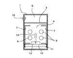
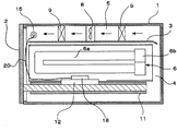
図1および図2に本発明のインプラント用紫外線照射装置の概要が示されている。図1において、本発明のインプラント用紫外線照射装置は、密閉型の筐体1と、該筐体1に対して気密に開閉される扉2とを備えている。前記筐体1内は隔壁3によって処理室4とオゾン処理室5とに区画され、処理室4内には紫外線ランプ6が配設されている。
上記紫外線ランプ6は、例えば波長185~254nmの紫外線を放射する低圧水銀ランプであって、筐体1の奥行き方向に伸びる2つの直線状部分が湾曲部分によって連結されてなるU字管状の発光管6aを有し、この2つの直線状部分が互いに上下に位置する関係で、直線状部分の長手方向が略水平方向となるように配置されていて、その一方端にはベース6bが取り付けられている。
図2に示されるように、該紫外線ランプ6処理室4内で対向するように一対配置されている。また、前記紫外線ランプ6を取り囲むように反射鏡7が筺体1に設けられている。
オゾン処理室5には、筐体1内のガスを循環させるファン8と、オゾン除去手段9が配置されている。オゾン除去手段9は、例えば、無機繊維ペーパーにより形成されたハニカム構造体からなる基体に、たとえば二酸化マンガンよりなるオゾン除去用触媒が担持されてなるオゾン除去フィルターである。
前記ファン8によって、処理室4内のオゾンを含むガスはオゾン処理室5に流れ、オゾン除去手段9によってオゾンを除去されて、再び処理室4に流れるように循環される。
上記紫外線ランプ6は、例えば波長185~254nmの紫外線を放射する低圧水銀ランプであって、筐体1の奥行き方向に伸びる2つの直線状部分が湾曲部分によって連結されてなるU字管状の発光管6aを有し、この2つの直線状部分が互いに上下に位置する関係で、直線状部分の長手方向が略水平方向となるように配置されていて、その一方端にはベース6bが取り付けられている。
図2に示されるように、該紫外線ランプ6処理室4内で対向するように一対配置されている。また、前記紫外線ランプ6を取り囲むように反射鏡7が筺体1に設けられている。
オゾン処理室5には、筐体1内のガスを循環させるファン8と、オゾン除去手段9が配置されている。オゾン除去手段9は、例えば、無機繊維ペーパーにより形成されたハニカム構造体からなる基体に、たとえば二酸化マンガンよりなるオゾン除去用触媒が担持されてなるオゾン除去フィルターである。
前記ファン8によって、処理室4内のオゾンを含むガスはオゾン処理室5に流れ、オゾン除去手段9によってオゾンを除去されて、再び処理室4に流れるように循環される。
筺体1に設けられる開閉扉2は、この実施例では引き出し型であって、この扉2と一体にキャリッジ10が取り付けられており、該キャリッジ10は筐体1に設けられたガイド11よってガイドされて、扉2の開閉と連動して引き出し可能となっている。なお、図示されてはいないが、この扉2は筐体1に対してシーリング材によって気密に密閉される。
図3は、扉2と連動するキャリッジ10上にインプラント保持体12が載置された状態の説明図であって、キャリッジ10上にインプラント保持体12を載置して扉2を閉めると、当該保持体12に支持されたデンタルインプラント13が、上記一対の紫外線ランプ6、6間に位置し、かつ該インプラント13が前記紫外線ランプ6の長さ方向の有効発光領域内に収まるように配置されている。
このインプラント保持体12には複数の保持孔12aが所定間隔で形成されており、インプラント13は、人体に埋め込まれる螺子部13aが上方を向くように、その端部13bを該保持孔12aに挿入することによって支持される。
図3は、扉2と連動するキャリッジ10上にインプラント保持体12が載置された状態の説明図であって、キャリッジ10上にインプラント保持体12を載置して扉2を閉めると、当該保持体12に支持されたデンタルインプラント13が、上記一対の紫外線ランプ6、6間に位置し、かつ該インプラント13が前記紫外線ランプ6の長さ方向の有効発光領域内に収まるように配置されている。
このインプラント保持体12には複数の保持孔12aが所定間隔で形成されており、インプラント13は、人体に埋め込まれる螺子部13aが上方を向くように、その端部13bを該保持孔12aに挿入することによって支持される。
上記構成において、インプラントの洗浄処理は以下のように行われる。
扉2の解放状態で、インプラント13が載置されたインプラント保持体12が、キャリッジ10上に載置固定される。そして、扉2を閉じることにより、筺体1は密閉され、このとき、図1に示すように、インプラント13は紫外線ランプ6間に位置するようになる。
紫外線ランプ6を点灯すると、筺体1内にはオゾンが発生し、該オゾンと紫外線によりインプラント13の洗浄が行なわれる。洗浄後、ランプ6を消灯し、その後ファンを駆動して処理室4内の雰囲気をオゾン処理室に循環し、この間にオゾン除去フィルター9によりオゾン除去処理が行われる。
このオゾン除去処理が終了したのち、扉2を開けてインプラント保持体10を取り出し、インプラント13を手術に供するものである。
扉2の解放状態で、インプラント13が載置されたインプラント保持体12が、キャリッジ10上に載置固定される。そして、扉2を閉じることにより、筺体1は密閉され、このとき、図1に示すように、インプラント13は紫外線ランプ6間に位置するようになる。
紫外線ランプ6を点灯すると、筺体1内にはオゾンが発生し、該オゾンと紫外線によりインプラント13の洗浄が行なわれる。洗浄後、ランプ6を消灯し、その後ファンを駆動して処理室4内の雰囲気をオゾン処理室に循環し、この間にオゾン除去フィルター9によりオゾン除去処理が行われる。
このオゾン除去処理が終了したのち、扉2を開けてインプラント保持体10を取り出し、インプラント13を手術に供するものである。
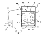
しかして、本発明においては、筺体1の隔壁3の上方のオゾン処理室6側の側壁にコネクタ15が壁を貫通し、かつ、気密状態で取り付けられている。
図4に示すように、紫外線センサ16は、本体部17と受光部18とからなり、前記本体部17には、表示部17aと操作部17bとが設けられている。そして、前記本体部17と受光部18には、それぞれ、ケーブル19とケーブル20が接続されていて、これらのケーブル19、20は、それぞれコネクタ15に着脱可能に接続される。即ち、本体部17のケーブル19は筺体1の外部から前記コネクタ15に接続され、受光部18のケーブル20は筺体1の内部からコネクタ15に接続される。
なお、図示していないが、各ケーブル19、20の先端には接続プラグが取り付けられていて、該接続プラグを介してコネクタ15に接続される。
図4に示すように、紫外線センサ16は、本体部17と受光部18とからなり、前記本体部17には、表示部17aと操作部17bとが設けられている。そして、前記本体部17と受光部18には、それぞれ、ケーブル19とケーブル20が接続されていて、これらのケーブル19、20は、それぞれコネクタ15に着脱可能に接続される。即ち、本体部17のケーブル19は筺体1の外部から前記コネクタ15に接続され、受光部18のケーブル20は筺体1の内部からコネクタ15に接続される。
なお、図示していないが、各ケーブル19、20の先端には接続プラグが取り付けられていて、該接続プラグを介してコネクタ15に接続される。
図5、図6には紫外線センサ1の受光部16がキャリッジ10上に載置された状態が示されている。
図5において、(A)は上面図であり、(B)はその側面図である。同図において、キャリッジ10には位置決め手段としてピン22が立設されている。なお、図5(A)においては、一方の位置決めピン22は省略して記載されている。
受光部18が載置固定される受光部載置台23の両端には、前記位置決めピン22に合致する凹部24が形成されている。
受光部18が載置された受光部載置台18は、図5(B)の上方からキャリッジ10上に載置される。このとき、位置決めピン22と凹部24とが係合することで位置決めされる。
図5において、(A)は上面図であり、(B)はその側面図である。同図において、キャリッジ10には位置決め手段としてピン22が立設されている。なお、図5(A)においては、一方の位置決めピン22は省略して記載されている。
受光部18が載置固定される受光部載置台23の両端には、前記位置決めピン22に合致する凹部24が形成されている。
受光部18が載置された受光部載置台18は、図5(B)の上方からキャリッジ10上に載置される。このとき、位置決めピン22と凹部24とが係合することで位置決めされる。
図6には、受光部載置台23の別の位置決め手段が示されていて、キャリッジ10に位置決め凹部25が形成され、受光部載置台23はこの凹部25内に収容されるようにキャリッジ10上に載置される。
なお、位置決め手段に関しては、これらの他に種々の変形が可能である。
なお、位置決め手段に関しては、これらの他に種々の変形が可能である。
紫外線ランプ6の照度モニターに当たっては、扉2を開放してキャリッジ10上に受光部載置台23を載置し、その上に受光部18を載置する。
そして、受光部18のケーブル20をコネクタ15に接続する。
この状態で扉2を閉めて、筺体1を密閉する。
一方、紫外線センサ16の本体部17のケーブル19を筺体1の外部からコネクタ15に接続する。
この状態で、紫外線ランプ6を点灯させてその照度を測定するものである。
そして、受光部18のケーブル20をコネクタ15に接続する。
この状態で扉2を閉めて、筺体1を密閉する。
一方、紫外線センサ16の本体部17のケーブル19を筺体1の外部からコネクタ15に接続する。
この状態で、紫外線ランプ6を点灯させてその照度を測定するものである。
なお、上記説明においては、キャリッジ10は開閉扉2と一体化したものを説明したが、これとは別体であってもよく、その場合、扉2は、キャリッジ10のガイド11とは別のガイド機構によって引き出し・収納可能に設けられる。
また、筐体1に対する開閉扉2としては、上記引き出し型の扉以外に、蝶番によるスイング式の回動扉であってもよく、その場合も、インプラント保持体12を載置するキャリッジ10は、扉2の開閉とは別に引き出し可能としてもよいし、扉2の回動に連動して水平状態を保って進退するようにしてもよい。
また、筐体1に対する開閉扉2としては、上記引き出し型の扉以外に、蝶番によるスイング式の回動扉であってもよく、その場合も、インプラント保持体12を載置するキャリッジ10は、扉2の開閉とは別に引き出し可能としてもよいし、扉2の回動に連動して水平状態を保って進退するようにしてもよい。
以上説明したように、本発明のインプラント用紫外線照射装置では、筺体の内部に紫外線ランプを有し、インプラント保持体を筺体内に搬出入するキャリッジを有し、前記筐体の壁に、該筺体内で紫外線センサの受光部へのケーブルが着脱可能に接続され、筺体外で紫外線センサの本体部へのケーブルが着脱可能に接続されるコネクタが設けられ、該コネクタと前記紫外線ランプとの間には紫外線を遮蔽する隔壁が設けられていることにより、紫外線ランプの照度モニターを行うときに、受光部を筺体内に収容すればよいので、紫外線による劣化の影響が少なくて済む。
その際には、コネクタには、筺体内部から受光部のケーブルと筺体外部から本体部のケーブルを接続するので、筺体の機密状態を保ったままでモニターすることができる。
また、コネクタは隔壁によって紫外線ランプからの紫外線を遮断されるので、紫外線ダメージを回避できる。
また、受光部の筺体内での設置には、インプラント保持体を搬出入するキャリッジを利用することで、簡便にその位置決めができる。
その際には、コネクタには、筺体内部から受光部のケーブルと筺体外部から本体部のケーブルを接続するので、筺体の機密状態を保ったままでモニターすることができる。
また、コネクタは隔壁によって紫外線ランプからの紫外線を遮断されるので、紫外線ダメージを回避できる。
また、受光部の筺体内での設置には、インプラント保持体を搬出入するキャリッジを利用することで、簡便にその位置決めができる。
1 筐体
2 扉
3 隔壁
4 処理室
5 オゾン処理室
6 紫外線ランプ
7 反射鏡
8 ファン
9 オゾン除去手段
10 キャリッジ
11 ガイド
12 インプラント保持体
13 インプラント
15 コネクタ
16 紫外線センサ
17 本体部
18 受光部
19 ケーブル
20 ケーブル
22 受光部載置台
23 凹部
24 位置決めピン
25 位置決め凹部
2 扉
3 隔壁
4 処理室
5 オゾン処理室
6 紫外線ランプ
7 反射鏡
8 ファン
9 オゾン除去手段
10 キャリッジ
11 ガイド
12 インプラント保持体
13 インプラント
15 コネクタ
16 紫外線センサ
17 本体部
18 受光部
19 ケーブル
20 ケーブル
22 受光部載置台
23 凹部
24 位置決めピン
25 位置決め凹部
Claims (3)
- 紫外線によりインプラントの有機汚染物除去を行うためのインプラント用紫外線照射装置において、
前記インプラント用紫外線照射装置は、
筐体と、
該筐体の内部に配置された紫外線ランプと、
インプラントが保持されるインプラント保持体が載置されて、前記筺体内にインプラント保持体を搬出入するための引出し可能なキャリッジと、
を有するとともに、
前記筐体の壁には、該筺体内で紫外線センサの受光部へのケーブルが着脱可能に接続され、筺体外で紫外線センサの本体部へのケーブルが着脱可能に接続されるコネクタが設けられ、
該コネクタと前記紫外線ランプとの間には紫外線を遮蔽する隔壁が設けられている、
ことを特徴とするインプラント用紫外線照射装置。 - 前記隔壁は、前記筺体内を紫外線ランプが収納される処理室と、オゾン除去手段が配置されるオゾン処理室とに区画していて、前記コネクタは前記オゾン処理室側に配置されていることを特徴とする請求項1に記載のインプラント用紫外線照射装置。
- 前記キャリッジには、前記紫外線センサの受光部を位置決めする位置決め手段が設けられていることを特徴とする請求項1に記載のインプラント用紫外線照射装置。
Applications Claiming Priority (2)
| Application Number | Priority Date | Filing Date | Title |
|---|---|---|---|
| JP2011041173A JP5299451B2 (ja) | 2011-02-28 | 2011-02-28 | インプラント用紫外線照射装置 |
| JP2011-041173 | 2011-02-28 |
Publications (1)
| Publication Number | Publication Date |
|---|---|
| WO2012117903A1 true WO2012117903A1 (ja) | 2012-09-07 |
Family
ID=46757842
Family Applications (1)
| Application Number | Title | Priority Date | Filing Date |
|---|---|---|---|
| PCT/JP2012/054190 Ceased WO2012117903A1 (ja) | 2011-02-28 | 2012-02-22 | インプラント用紫外線照射装置 |
Country Status (2)
| Country | Link |
|---|---|
| JP (1) | JP5299451B2 (ja) |
| WO (1) | WO2012117903A1 (ja) |
Cited By (1)
| Publication number | Priority date | Publication date | Assignee | Title |
|---|---|---|---|---|
| EP3266411A4 (en) * | 2015-03-05 | 2018-05-30 | Ushio Denki Kabushiki Kaisha | Ultraviolet irradiation device for implant |
Citations (4)
| Publication number | Priority date | Publication date | Assignee | Title |
|---|---|---|---|---|
| JPH01207070A (ja) * | 1987-10-22 | 1989-08-21 | Jr Robert E Duthie | 滅菌方法および装置 |
| US20040099812A1 (en) * | 2001-11-28 | 2004-05-27 | Humphreys Wesley G. | Apparatus for neutralizing chemical and biological threats |
| JP2005053520A (ja) * | 2003-08-01 | 2005-03-03 | Iwasaki Electric Co Ltd | 光パルス殺菌装置 |
| US20070023710A1 (en) * | 2005-07-08 | 2007-02-01 | Amarante Technologies, Inc. | Closed-loop control of ultraviolet (UV) sterilization systems |
Family Cites Families (2)
| Publication number | Priority date | Publication date | Assignee | Title |
|---|---|---|---|---|
| JPH04935U (ja) * | 1990-04-18 | 1992-01-07 | ||
| JP4300379B2 (ja) * | 1999-10-29 | 2009-07-22 | 東芝ライテック株式会社 | 照明器具 |
-
2011
- 2011-02-28 JP JP2011041173A patent/JP5299451B2/ja not_active Expired - Fee Related
-
2012
- 2012-02-22 WO PCT/JP2012/054190 patent/WO2012117903A1/ja not_active Ceased
Patent Citations (4)
| Publication number | Priority date | Publication date | Assignee | Title |
|---|---|---|---|---|
| JPH01207070A (ja) * | 1987-10-22 | 1989-08-21 | Jr Robert E Duthie | 滅菌方法および装置 |
| US20040099812A1 (en) * | 2001-11-28 | 2004-05-27 | Humphreys Wesley G. | Apparatus for neutralizing chemical and biological threats |
| JP2005053520A (ja) * | 2003-08-01 | 2005-03-03 | Iwasaki Electric Co Ltd | 光パルス殺菌装置 |
| US20070023710A1 (en) * | 2005-07-08 | 2007-02-01 | Amarante Technologies, Inc. | Closed-loop control of ultraviolet (UV) sterilization systems |
Cited By (1)
| Publication number | Priority date | Publication date | Assignee | Title |
|---|---|---|---|---|
| EP3266411A4 (en) * | 2015-03-05 | 2018-05-30 | Ushio Denki Kabushiki Kaisha | Ultraviolet irradiation device for implant |
Also Published As
| Publication number | Publication date |
|---|---|
| JP5299451B2 (ja) | 2013-09-25 |
| JP2012176160A (ja) | 2012-09-13 |
Similar Documents
| Publication | Publication Date | Title |
|---|---|---|
| KR101440251B1 (ko) | 생체 임플란트용 세정 처리 장치 | |
| US8729501B2 (en) | Ultraviolet irradiation device for implants | |
| JP5387537B2 (ja) | デンタルインプラント用光照射装置 | |
| KR101705830B1 (ko) | 치아 임플란트용 포장용기 | |
| JP4867883B2 (ja) | 殺菌装置 | |
| US20070023710A1 (en) | Closed-loop control of ultraviolet (UV) sterilization systems | |
| WO2012105093A1 (ja) | インプラント用紫外線照射装置 | |
| KR101675508B1 (ko) | 치아 임플란트용 포장용기 | |
| KR101991785B1 (ko) | 치아 임플란트의 표면처리용 자외선 조사장치 | |
| JP5838566B2 (ja) | インプラント用紫外線照射装置 | |
| KR102476398B1 (ko) | 플라즈마 처리 장치 및 이를 이용한 방법 | |
| JP5299451B2 (ja) | インプラント用紫外線照射装置 | |
| KR102590340B1 (ko) | 임플란트의 표면처리용 자외선 조사장치 | |
| US20190151485A1 (en) | Disinfecting and sterilizing device for medical sensor | |
| KR20220070602A (ko) | 내시경 살균기 | |
| JP6048915B2 (ja) | インプラント用紫外線照射装置 | |
| KR100940602B1 (ko) | 치공구용 회전 스탠드 | |
| JP2012000118A (ja) | 人工歯根の有機汚染物除去装置 | |
| JP2012000120A (ja) | 人工歯根の有機汚染物除去装置 | |
| EP1720581A4 (en) | UV STERILIZER OF DENTAL HANDPIECES | |
| KR20190088759A (ko) | 치아 임플란트의 표면처리용 자외선 조사장치 | |
| JP2012000119A (ja) | 人工歯根の有機汚染物除去装置 | |
| KR101834767B1 (ko) | 치아 임플란트용 포장용기 전원공급장치 | |
| WO2011158680A1 (ja) | 人工歯根の有機汚染物除去装置 | |
| CN220524309U (zh) | 一种无臭氧uvc空气杀菌器 |
Legal Events
| Date | Code | Title | Description |
|---|---|---|---|
| 121 | Ep: the epo has been informed by wipo that ep was designated in this application |
Ref document number: 12751981 Country of ref document: EP Kind code of ref document: A1 |
|
| NENP | Non-entry into the national phase |
Ref country code: DE |
|
| 122 | Ep: pct application non-entry in european phase |
Ref document number: 12751981 Country of ref document: EP Kind code of ref document: A1 |