WO2012117598A1 - ロータリーコンプレッサ - Google Patents
ロータリーコンプレッサ Download PDFInfo
- Publication number
- WO2012117598A1 WO2012117598A1 PCT/JP2011/071492 JP2011071492W WO2012117598A1 WO 2012117598 A1 WO2012117598 A1 WO 2012117598A1 JP 2011071492 W JP2011071492 W JP 2011071492W WO 2012117598 A1 WO2012117598 A1 WO 2012117598A1
- Authority
- WO
- WIPO (PCT)
- Prior art keywords
- cylinder
- vane
- rotary
- roller
- rotary compressor
- Prior art date
- Legal status (The legal status is an assumption and is not a legal conclusion. Google has not performed a legal analysis and makes no representation as to the accuracy of the status listed.)
- Ceased
Links
Images

Classifications
-
- F—MECHANICAL ENGINEERING; LIGHTING; HEATING; WEAPONS; BLASTING
- F04—POSITIVE - DISPLACEMENT MACHINES FOR LIQUIDS; PUMPS FOR LIQUIDS OR ELASTIC FLUIDS
- F04C—ROTARY-PISTON, OR OSCILLATING-PISTON, POSITIVE-DISPLACEMENT MACHINES FOR LIQUIDS; ROTARY-PISTON, OR OSCILLATING-PISTON, POSITIVE-DISPLACEMENT PUMPS
- F04C18/00—Rotary-piston pumps specially adapted for elastic fluids
- F04C18/30—Rotary-piston pumps specially adapted for elastic fluids having the characteristics covered by two or more of groups F04C18/02, F04C18/08, F04C18/22, F04C18/24, F04C18/48, or having the characteristics covered by one of these groups together with some other type of movement between co-operating members
- F04C18/34—Rotary-piston pumps specially adapted for elastic fluids having the characteristics covered by two or more of groups F04C18/02, F04C18/08, F04C18/22, F04C18/24, F04C18/48, or having the characteristics covered by one of these groups together with some other type of movement between co-operating members having the movement defined in group F04C18/08 or F04C18/22 and relative reciprocation between the co-operating members
- F04C18/356—Rotary-piston pumps specially adapted for elastic fluids having the characteristics covered by two or more of groups F04C18/02, F04C18/08, F04C18/22, F04C18/24, F04C18/48, or having the characteristics covered by one of these groups together with some other type of movement between co-operating members having the movement defined in group F04C18/08 or F04C18/22 and relative reciprocation between the co-operating members with vanes reciprocating with respect to the outer member
- F04C18/3562—Rotary-piston pumps specially adapted for elastic fluids having the characteristics covered by two or more of groups F04C18/02, F04C18/08, F04C18/22, F04C18/24, F04C18/48, or having the characteristics covered by one of these groups together with some other type of movement between co-operating members having the movement defined in group F04C18/08 or F04C18/22 and relative reciprocation between the co-operating members with vanes reciprocating with respect to the outer member the inner and outer member being in contact along one line or continuous surfaces substantially parallel to the axis of rotation
- F04C18/3564—Rotary-piston pumps specially adapted for elastic fluids having the characteristics covered by two or more of groups F04C18/02, F04C18/08, F04C18/22, F04C18/24, F04C18/48, or having the characteristics covered by one of these groups together with some other type of movement between co-operating members having the movement defined in group F04C18/08 or F04C18/22 and relative reciprocation between the co-operating members with vanes reciprocating with respect to the outer member the inner and outer member being in contact along one line or continuous surfaces substantially parallel to the axis of rotation the surfaces of the inner and outer member, forming the working space, being surfaces of revolution
-
- F—MECHANICAL ENGINEERING; LIGHTING; HEATING; WEAPONS; BLASTING
- F01—MACHINES OR ENGINES IN GENERAL; ENGINE PLANTS IN GENERAL; STEAM ENGINES
- F01C—ROTARY-PISTON OR OSCILLATING-PISTON MACHINES OR ENGINES
- F01C21/00—Component parts, details or accessories not provided for in groups F01C1/00 - F01C20/00
- F01C21/10—Outer members for co-operation with rotary pistons; Casings
- F01C21/104—Stators; Members defining the outer boundaries of the working chamber
- F01C21/106—Stators; Members defining the outer boundaries of the working chamber with a radial surface, e.g. cam rings
-
- F—MECHANICAL ENGINEERING; LIGHTING; HEATING; WEAPONS; BLASTING
- F04—POSITIVE - DISPLACEMENT MACHINES FOR LIQUIDS; PUMPS FOR LIQUIDS OR ELASTIC FLUIDS
- F04C—ROTARY-PISTON, OR OSCILLATING-PISTON, POSITIVE-DISPLACEMENT MACHINES FOR LIQUIDS; ROTARY-PISTON, OR OSCILLATING-PISTON, POSITIVE-DISPLACEMENT PUMPS
- F04C23/00—Combinations of two or more pumps, each being of rotary-piston or oscillating-piston type, specially adapted for elastic fluids; Pumping installations specially adapted for elastic fluids; Multi-stage pumps specially adapted for elastic fluids
- F04C23/008—Hermetic pumps
Definitions
- the present invention relates to a rotary compressor provided with a drive element and a rotary compression element in an airtight container.
- a rotary compressor of a multistage compression type is known, and when this compressor is energized through a terminal and a wiring provided in an end cap of a hermetic container, the drive element is activated.
- the rotor rotates. Due to the rotation of the rotor, the first and second rollers fitted to the first and second eccentric portions provided integrally with the rotation shaft of the drive element rotate eccentrically in the first and second cylinders.
- low-pressure refrigerant gas is drawn into the low-pressure chamber side of the first cylinder through the refrigerant introduction pipe and the first suction passage formed in the first support member.
- the low-pressure refrigerant gas sucked into the low-pressure chamber side of the first cylinder is compressed by the first stage by the operation of the first roller and the first vane to become an intermediate pressure, and the high-pressure chamber of the first cylinder. It is discharged from the side through the discharge port into the discharge silencer chamber.
- the intermediate-pressure refrigerant gas discharged into the discharge silencing chamber is sucked into the low pressure chamber side of the second cylinder through the second suction passage formed on the lower surface side of the second cylinder from the discharge silencing chamber. Is done.
- the intermediate-pressure refrigerant gas sucked into the low-pressure chamber side in the second cylinder is compressed in the second stage by the operation of the second roller and the second vane to become a high-temperature and high-pressure refrigerant gas. Is discharged from the high pressure chamber side of the cylinder through the discharge port into the discharge silencer chamber formed by the second support member and the second cover.
- the refrigerant gas discharged into the discharge silencer chamber is discharged into the hermetic container via a discharge hole formed in the second cover.
- the refrigerant gas discharged into the hermetic container rises between the stator and rotor of the drive element or through the gap between the hermetic container and stator, and moves to the space between the end cap and the drive element. It is discharged to the outside of the rotary compressor from a refrigerant discharge pipe that opens into the space (Patent Document 1).
- the first and second vanes are slidably provided in the vane slots.
- the first and second vanes are always urged against the rollers by springs, thereby preventing refrigerant leakage and improving the operation efficiency of the rotary compressor.
- the refrigerant discharged to the outside of the rotary compressor is gas-liquid separated by an accumulator, and only the refrigerant gas is sucked into the low pressure chamber side of the first cylinder, and this is repeated.
- an object of the present invention is to provide a rotary compressor that can suppress a decrease in operating efficiency due to vane jumping.
- the present invention relates to a compressor including a drive element and a rotary compression element driven by a rotary shaft of the drive element in an airtight container, wherein the rotary compression element is a cylinder and an eccentric portion formed on the rotary shaft.
- the rotary compression element is a cylinder and an eccentric portion formed on the rotary shaft.
- a roller that is fitted in the eccentric portion and rotates eccentrically in the cylinder, a vane that abuts the roller and divides the inside of the cylinder into a high pressure chamber and a low pressure chamber, and is formed in the cylinder and moves the vane Vane slots that can be freely stored and opened in the sealed container, and the cylinder has a communication portion that communicates the inside of the cylinder and the sealed container when the vane is separated from the roller. It is characterized by that.
- the communication portion may be a groove formed along the vane slot on the surface of the cylinder.
- the communication portion may be a groove formed on the surface of the cylinder so as to intersect with the vane slot.
- the communication part may be a groove formed along the vane slot on the wall surface of the vane slot.
- the communication portion may be a groove that penetrates the wall surface of the vane slot so as to intersect the vane slot.
- a discharge port formed in the cylinder may be provided, and the communication portion may be formed closer to the discharge port than the center of the vane slot.
- the rotary compression element may compress the carbon dioxide refrigerant.
- a communication portion that communicates between the inside of the cylinder and the inside of the vane slot is formed when the vane is separated from the roller. It is possible to escape from the vane slot into the sealed container through the section, and quickly eliminate the liquid compression state.
- FIG. 4 is a view corresponding to FIG. 3 showing another embodiment.
- FIG. 4 is a view corresponding to FIG. 3 showing another embodiment.
- FIG. 7 is a cross-sectional view taken along the line AA in FIG. 6.
- FIG. 4 is a view corresponding to FIG. 3 showing still another embodiment.
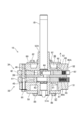
- FIG. 1 is a longitudinal side view of a rotary compressor to which the present invention is applied
- FIG. 2 is a longitudinal side view of a rotary compression element constituting the rotary compressor of the present invention.
- a rotary compressor 10 shown in FIG. 1 includes a vertical cylindrical airtight container 12 made of a steel plate, a drive element 14 disposed in an upper space in the airtight container 12, and a space below the drive element 14.
- the first rotary compression element 32 and the second rotary compression element 32 are arranged and driven by the rotary shaft 16 of the drive element 14 to constitute the rotary compression element 18.
- the rotary compressor 10 is a so-called internal high pressure type in which the refrigerant is compressed by the first rotary compression element 32 and further compressed by the second rotary compression element 34 and then discharged into the sealed container 12. This is a multistage compression type rotary compressor.
- the sealed container 12 includes a container body 12A that houses the drive element 14, the first and second rotary compression elements 32 and 34, and a substantially bowl-shaped end cap 12B (lid body) that closes the upper opening of the container body 12A. ), And the bottom is an oil reservoir 19.
- a circular mounting hole 12C is formed on the upper surface of the end cap 12B, and a terminal 20 (wiring is omitted) for supplying power to the driving element 14 is mounted in the mounting hole 12C.
- the drive element 14 includes a stator 22 that is welded and fixed in an annular shape along the inner peripheral surface of the upper space of the sealed container 12, and a rotor 24 that is inserted and installed inside the stator 22 with a slight gap therebetween. ing.
- the rotor 24 is fixed to a rotary shaft 16 that passes through the center of the sealed container 12 and extends in the vertical direction.
- the stator 22 includes a laminated body 26 in which annular electromagnetic steel plates are laminated, and a stator coil 28 wound around a tooth portion of the laminated body 26 by a direct winding (concentrated winding) method.
- the rotor 24 is also composed of a laminated body 30 of electromagnetic steel plates.
- the first and second rotary compression elements 32 and 34 are arranged with the first rotary compression element 32 that is the first stage compression on the opposite side of the drive element 14 with the intermediate partition plate 36 interposed therebetween (in this case,
- the second rotary compression element 34 that is the second-stage compression is disposed on the drive element 14 side in the hermetic container 12 (in this case, the upper side of the rotary compressor 10 and the lower side of the rotary compressor 10). Become).
- first and second rotary compression elements 32 and 34 are arranged such that the second rotary compression element 34 in the second stage is interposed between the intermediate partition plate 36 as shown in FIG.
- the first rotary compression element 32 which is the 14th side and the first stage is arranged on the side opposite to the drive element 14.
- the first rotary compression element 32 and the second rotary compression element 34 are arranged above and below the intermediate partition plate 36, and the first and second rotary compression elements 32, 34 constituting the first and second rotary compression elements 32, 34.
- the cylinders 41 and 42 (upper and lower cylinders) and the first and second eccentric parts 43 and 44 (upper and lower eccentric parts) formed on the rotary shaft 16 of the drive element 14 are fitted into the cylinders 41 and 42 to rotate eccentrically.
- the first roller 45 and the second roller 46 are provided.
- the first rotary compression element 32 and the second rotary compression element 34 are in contact with the rollers 45 and 46, respectively, and divide the cylinders 41 and 42 into a low pressure chamber side and a high pressure chamber side, respectively.
- Second vanes 47 and 48 (not shown in FIG. 1), and first and second springs 85 and 86 as spring members for constantly biasing the vanes 47 and 48 toward the rollers 45 and 46,
- a first support member 51 (lower support member) as a support member that closes one (lower side) opening of the first cylinder 41 (lower cylinder) and has a bearing 51A of the rotating shaft 16;
- the upper opening of the cylinder 42 (upper cylinder) is closed, and the second support member 52 (upper support member) having the bearing 52A of the rotating shaft 16 is configured.
- first cylinder 41 constituting the first rotary compression element 32
- first support member 51 one (lower side) opening of the first cylinder 41 constituting the first rotary compression element 32 is closed by the first support member 51
- the other (upper side) opening is closed by the intermediate partition plate 36.
- the first and second eccentric parts 43 and 44 are provided on the rotating shaft 16 with a phase difference of 180 degrees.
- the second support member 52 and the first support member 51 have first and second suction passages 53 and 54 communicating with the insides of the first and second cylinders 41 and 42, respectively (only FIG. 1 is shown).
- the discharge formed by recessing the surface (upper side) opposite to the second cylinder 42 of the second support member 52 and closing the recess with the second cover 60 (upper cover).
- the silencing chamber 58 and the first support member 51 on the opposite side (lower side) of the first cylinder 41 are recessed, and the recessed portion is closed by the first cover 59 (lower cover).
- a discharge silencer chamber 57 is provided.
- the second cover 60 is formed with a discharge hole 65 (shown only in FIG. 1) that allows the discharge silencer chamber 58 and the inside of the sealed container 12 to communicate with each other.
- the discharge silencing chamber 58 is closed with a second cover 60, and the discharge silencing chamber 57 is closed with a first cover 59.
- a bearing 52 ⁇ / b> A is formed upright at the center of the second support member 52, and a bearing 51 ⁇ / b> A is formed through the center of the first support member 51. Then, the second cover 60, the second support member 52, and the second cylinder 42 are positioned, and the four upper bolts from the second cover 60 side (upper side) to the first cover 59 direction (downward direction).
- the first cover 59 is composed of a donut-shaped circular steel plate, and four bolts 80 are arranged at four locations in the peripheral portion from the first cover 59 side (lower side) to the second cover 60 direction (upward direction). ... (only two are shown) are fixed to the second cylinder 42 to close the lower surface opening of the discharge silencing chamber 57 communicating with the inside of the first cylinder 41 constituting the first rotary compression element 32.
- two bolts 81 are installed on the first support member 51, and these bolts 81 are screwed onto the second support member 52, so that the first support member 51 and the second support member 52 are fixed integrally.
- a first vane slot 61 (see FIG. 3) for storing the first vane 47 in the first cylinder 41, and an outer side of the first vane slot 61 (closed container 12 side),
- a storage portion 85A for storing a first spring 85 as a spring member (coil spring) that constantly biases the first vane 47 toward the first roller 45 is formed.
- the storage portion 85A opens to the first vane 47 side and the closed container 12 side.
- the first spring 85 is in contact with the outer end portion of the first vane 47 and constantly urges the first vane 47 toward the first roller 45.
- the storage portion 86A is open to the second vane 48 side and the closed container 12 side.
- the second spring 86 also abuts on the outer end portion of the second vane 48 and constantly urges the second vane 48 toward the second roller 48 side.
- a metal plug 92 that serves to prevent the spring 86 from coming off is press-fitted into the housing 86A located on the airtight container 12 side of the spring 86 from the outside (sealed container 12 side) of the housing 86A.
- the outer diameter of the plug 92 is set slightly larger than the inner diameter of the storage portion 86A, and the plug 92 is press-fitted and fixed in the storage portion 86A.
- a communication portion A (see FIG. 2) is provided, and the vane back pressure is reduced in the sealed container 12 by the communication portion A. It plays the role of gas pressure (high pressure).
- a communication portion 37 is provided for communicating the first vane slot 61 and the inside of the sealed container 12 in order to return the compressed liquid into the sealed container 12.
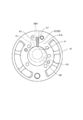
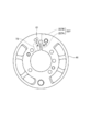
- the communication portion 37 is formed as a long groove 38 that is recessed by engraving the upper surface 41 ⁇ / b> A of the first cylinder 41 along the first vane slot 61 in the first cylinder 41.
- the long groove 38 (hereinafter referred to as the communication portion 37) extends along one side of the first vane 47 that fits in the first vane slot 61, and is formed in a substantially linear shape up to the first spring 85 storage portion. Has been.
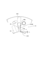
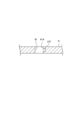
- One end 37 ⁇ / b> A of the communication portion 37 does not penetrate through the inner surface 41 ⁇ / b> B of the first cylinder 41 as shown in FIG. 4.
- One end 37 ⁇ / b> A of the communication portion 37 terminates away from the inner surface 41 ⁇ / b> B by a dimension L, and is positioned in the first vane slot 61 in which the first vane 47 slides.
- the other end 37 ⁇ / b> B of the communication portion 37 communicates with the storage portion 85 ⁇ / b> A of the first spring 85.
- the first spring 85 is inserted into the storage portion 85A of the first spring 85 from the opening outside the storage portion 85A (closed container 12 side), and the end portion is press-fitted and fixed.
- the first spring 85 is formed such that 6 to 10 turns on the inner surface side of the sealed container 12 are slightly larger than the inner diameter of the storage portion 85A, and the first vane 47 side is connected to the storage portion 85A.
- the diameter is slightly smaller than the inner diameter.
- the first spring 85 is press-fitted and fixed in the storage portion 85A, and the first vane 47 is constantly biased toward the first roller 45. That is, the inside of the first spring 85 serves as a communication portion (not shown), and the inside of the storage portion 85A communicates with the inside of the sealed container 12.
- the first cylinder 41 has a first suction port 73 on one side (low pressure side) across the first vane 47 and a first discharge port 71 on the other side (high pressure side). Yes. Specifically, a first suction port 73 for sucking refrigerant is opened on the low pressure side of the first cylinder 41, and the first suction port 73 is located at a position spaced apart from the first vane 47 by a predetermined distance. Is formed. A first discharge port 71 for discharging a high-temperature and high-pressure refrigerant is opened on the high-pressure side of the first cylinder 41, and the first discharge port 71 is a first vane on the inner surface of the first cylinder 41. It is formed near the slot 61.
- the one end 37 ⁇ / b> A of the communication portion 37 described above is formed at a position that does not overlap the first discharge port 71.
- the second cylinder 42 located downstream of the first cylinder 41 sucks and compresses the high-temperature and high-pressure refrigerant gas compressed in the first stage (first cylinder 41). In the first place, the refrigerant gas is not mixed into the refrigerant gas. For this reason, since the compression of the liquid refrigerant does not occur in the second cylinder 42, the communication portion 37 is not provided in the second cylinder 42.
- sleeves 93 are provided on the side surfaces of the container body 12 ⁇ / b> A constituting the sealed container 12 at positions corresponding to the upper side of the first suction passage 53 and the drive element 14 of the first cylinder 41. 95 is fixed by welding.
- One end of a refrigerant introduction pipe 94 for introducing refrigerant gas into the first cylinder 41 is inserted into and connected to the sleeve 93, and one end of the refrigerant introduction pipe 94 is connected to the first suction passage of the first cylinder 41. 53 is communicated.
- a refrigerant discharge pipe 96 is inserted and connected into the sleeve 95, and the refrigerant discharge pipe 96 is positioned on the upper side of the drive element 14 (on the terminal 20 side of the drive element 14), and an end portion is opened to communicate with the sealed container 12. ing.
- the low-pressure refrigerant gas is sucked into the low-pressure chamber side of the first cylinder 41 through the refrigerant introduction pipe 94 and the first suction passage 53 formed in the first support member 51.
- the low-pressure refrigerant gas sucked into the low-pressure chamber side of the first cylinder 41 is compressed by the first stage by the operation of the first roller 45 and the first vane 47 to become an intermediate pressure, and the first cylinder 41 is discharged into the discharge silencer chamber 57 from the high pressure chamber side through the discharge port.
- the intermediate-pressure refrigerant gas sucked into the low-pressure chamber side in the second cylinder 42 is compressed at the second stage by the operation of the second roller 46 and the second vane 48 to become a high-temperature and high-pressure refrigerant gas. From the high pressure chamber side of the second cylinder 42, it is discharged into a discharge silencer chamber 58 formed by the second support member 52 and the second cover 60 through a discharge port (not shown).
- the refrigerant gas discharged into the discharge silencer chamber 58 is discharged into the sealed container 12 through the discharge hole 65 formed in the second cover 60.
- the refrigerant gas discharged from the discharge hole 65 into the sealed container 12 rises between the stator 22 and the rotor 24 of the drive element 14, in the rotor 24, or through the gap between the sealed container 12 and the stator 22, and the drive element 14. It moves to the space with the upper end cap 12B, and is discharged from the opening of the refrigerant discharge pipe 96 connected to the upper side of the hermetic container 12 to the outside of the rotary compressor 10 through the refrigerant discharge pipe 96.
- the refrigerant discharged to the outside is not shown in the figure, the refrigerant is gas-liquid separated by an accumulator through a heat exchanger, an expansion valve, and a heat exchanger that constitute a refrigeration cycle. Repeated circulation inhaled.
- the liquid refrigerant may be sucked into the first cylinder 41 unless it is completely gas-liquid separated by the accumulator. Even when the accumulator is not provided, the liquid refrigerant may be sucked into the first cylinder 41. In this case, liquid compression occurs in the first cylinder 41, but when liquid compression occurs in the first cylinder 41, the first vane 47 is pushed by the liquid compression, and the vanes of the first vane 47 are pressed. The end portion P is separated from the first roller 45 (so-called vane jump). At this time, one end 37 ⁇ / b> A of the communication portion 37 is positioned in the vicinity of the first roller 45 in the first vane slot 61 as shown in FIG.
- the first vane 47 is the first roller 45.
- the first vane 47 floats upward in the drawing, the one end 37A of the communication portion 37 communicates with the inside of the first cylinder 41, and the first spring 85 is connected via the other end 37B of the communication portion 37.
- the high pressure of the refrigerant is released. That is, the first cylinder 41 communicates with the communication portion 37 by the separation of the first vane 47 (vane end portion P) and the first roller 45. Due to the communication in the first cylinder 41 and the communication portion 37, the liquid refrigerant compressed by liquid compression passes from the first cylinder 41 to the first vane slot 61 and the communication portion 37, and the first refrigerant is compressed.
- the first vane 47 when the first vane 47 is separated from the first roller 45, the first cylinder 41 and the storage portion 85A of the first spring 85 communicate with each other. Since the communication portion 37 is formed, when the first cylinder 41 constituting the rotary compression element 18 is in a liquid compression state and a so-called first vane 47 jump occurs, the liquid refrigerant in the first cylinder 41 Can be released into the sealed container 12 through the communication portion 37 and the storage portion 85 ⁇ / b> A of the first spring 85. Thereby, even when the inside of the first cylinder 41 is in a liquid compression state, the liquid compression state can be quickly eliminated.
- the communication portion 37 is formed integrally with the first cylinder 41, the relative positional relationship in the circumferential direction between the first vane 47 and the communication portion 37 is shifted. Will not occur. That is, even when a relative assembly shift in the circumferential direction occurs in each component, for example, the first cylinder 41 and the intermediate partition plate 36 when the rotary compressor 10 is assembled, the first vane 47 and the communication portion 37 There is no deviation in the positional relationship. Therefore, when the so-called vane jump occurs in the first vane 47, the communication part 37 functions accurately, so that the liquid refrigerant in the first cylinder 41 can be surely released into the sealed container 12, The liquid compression state can be quickly eliminated.
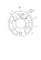
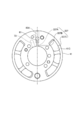
- FIG. 5 shows another embodiment.
- the same parts as those in the above-described embodiment are denoted by the same reference numerals, and description thereof is omitted.
- the first vane 47 and the first roller 45 are not shown.
- the upper surface 41A of the first cylinder 41 is formed with a communication portion 137 that functions in the same manner as in the previous embodiment.
- One end 137A of the communication portion 137 communicates with the first vane slot 61 and the other end.
- 137B extends in the horizontal direction in the drawing, communicates with the opening 41C of the first cylinder 41, and communicates with the inside of the sealed container 12 from here.
- the communication portion 37 that connects the inside of the first cylinder 41 and the opening 41C is provided.
- the liquid refrigerant in the first cylinder 41 is passed through the communication portion 37 and the opening 41 ⁇ / b> C. The air can be released into the sealed container 12, and the liquid compression state in the first cylinder 41 can be quickly eliminated.
- FIG. 6 and 7 show another embodiment. The same parts as those in the above-described embodiment are denoted by the same reference numerals, and description thereof is omitted.
- the inner wall surface 61A (see FIG. 7) of the first vane slot 61 of the first cylinder 41 has a communication portion 237 having a substantially rectangular cross section along the longitudinal direction of the first vane slot 61. Is formed.
- one end 237A of the communication portion 237 communicates with the first vane slot 61, and the other end 237B extends upward in the drawing, penetrates the first cylinder 41, and is sealed. It communicates with the inside of the container 12.
- the communication portion 237 that communicates the inside of the first cylinder 41 and the inside of the sealed container 12 is provided. 18, when the so-called first vane 47 jump occurs, the liquid refrigerant in the first cylinder 41 is supplied to the sealed container 12 via the communication portion 37. It can escape inside, and the liquid compression state can be eliminated.
- FIG. 8 shows yet another embodiment.
- the same parts as those in the above-described embodiment are denoted by the same reference numerals, and description thereof is omitted.
- the first vane 47 and the first roller 45 are not shown.
- a communication portion 337 that connects the first vane slot 61 of the first cylinder 41 and the opening 41C is formed.
- the communication portion 337 is formed by machining from the outer end 337 ⁇ / b> C of the first cylinder 41 toward the first vane slot 61.
- One end 337 ⁇ / b> A of the communication portion 337 opens into the first vane slot 61, and the other end 337 ⁇ / b> B extends in the horizontal direction in the drawing to communicate with the opening 41 ⁇ / b> C and further into the sealed container 12.
- the communication portion 337 that communicates the inside of the first cylinder 41 and the inside of the sealed container 12 is provided, the inside of the first cylinder 41 that constitutes the rotary compression element 18 is in a liquid compression state, so-called.
- the liquid refrigerant can escape into the sealed container 12 via the communication part 37.
- the present invention is not limited to this.
- the rotary compressor 10 may be applied to a rotary compressor using a highly compressed refrigerant (for example, nitrogen gas) other than carbon dioxide.
- a highly compressed refrigerant for example, nitrogen gas
- the multistage rotary compressor 10 has been described.
- the present embodiment may be applied to a single stage rotary compressor (not shown).
- the communication portions 37, 137, 237, and 337 are desirably provided on the upper surface 41 A of the first cylinder 41.
- the rotary compressor 10 has been described as a vertical type, the rotary compressor 10 is not limited to a vertical type and may be a horizontal type.
- the present invention is not limited to the configuration of the communication portions 37, 137, 237, and 337 shown in the above embodiment, and various other modifications can be made without departing from the spirit of the present invention.
- the present invention is also effective.
Landscapes
- Engineering & Computer Science (AREA)
- Mechanical Engineering (AREA)
- General Engineering & Computer Science (AREA)
- Applications Or Details Of Rotary Compressors (AREA)
Abstract
【課題】ベーン飛びによる運転効率の低下を抑制できるロータリーコンプレッサを提供することにある。 【解決手段】密閉容器内に駆動要素と、該駆動要素の回転軸にて駆動される回転圧縮要素を備えたコンプレッサにおいて、前記回転圧縮要素が、シリンダ41と、前記回転軸に形成された偏心部43と、前記偏心部に嵌合されてシリンダ内で偏心回転するローラ45と、前記ローラに当接してシリンダ内を高圧室と低圧室とに区画するベーン47と、前記シリンダに形成され、前記ベーンを移動自在に収納すると共に、前記密閉容器内に開放したベーンスロット61とを備え、前記シリンダ41に、前記ベーン47が前記ローラ45から離間したときに前記シリンダ41内と前記密閉容器内とを連通する連通部37を形成したことを特徴とする。
Description
本発明は、密閉容器内に駆動要素と回転圧縮要素とを備えたロータリーコンプレッサに関する。
一般に、多段圧縮式のロータリーコンプレッサが知られており、このコンプレッサは、密閉容器のエンドキャップに設けられたターミナル及び配線を介して駆動要素のステータコイルに通電されると、駆動要素が起動してロータが回転する。このロータの回転により駆動要素の回転軸と一体に設けた第1及び第2の偏心部に嵌合された第1及び第2のローラが第1及び第2のシリンダ内を偏心回転する。これにより、冷媒導入管及び第1の支持部材に形成された第1の吸込通路を経て、第1のシリンダの低圧室側に低圧の冷媒ガスが吸入される。第1のシリンダの低圧室側に吸入された低圧の冷媒ガスは、第1のローラと第1のベーンの動作により1段目の圧縮が行われて中間圧となり、第1のシリンダの高圧室側より吐出ポートを経て吐出消音室内に吐出される。
そして、吐出消音室に吐出された中間圧の冷媒ガスは、当該吐出消音室内から第2のシリンダの下面側に形成された第2の吸込通路を経て、第2のシリンダの低圧室側に吸入される。第2のシリンダ内の低圧室側に吸入された中間圧の冷媒ガスは、第2のローラと第2のベーンの動作により2段目の圧縮が行われて高温高圧の冷媒ガスとなり、第2のシリンダの高圧室側より吐出ポートを経て、第2の支持部材と第2のカバーにて形成された吐出消音室内に吐出される。吐出消音室内に吐出された冷媒ガスは、第2のカバーに形成された吐出孔を経由して密閉容器内に吐出される。密閉容器内に吐出された冷媒ガスは、駆動要素のステータとロータの間や、密閉容器とステータの隙間を通過して上昇し、エンドキャップと駆動要素との間の空間へと移動し、その空間に開口する冷媒吐出管からロータリーコンプレッサの外部に吐出される(特許文献1)。
ところで、従来の内部高圧型の多段圧縮式ロータリーコンプレッサでは、第1及び第2のベーンがそれぞれベーンスロット内に摺動自在に設けられている。第1及び第2のベーンはスプリングによって常時ローラに付勢されており、これによって、冷媒漏れを防止してロータリーコンプレッサの運転効率の向上が図られていた。ロータリーコンプレッサの外部に吐出された冷媒は、アキュムレータによって気液分離され、冷媒ガスだけが第1のシリンダの低圧室側に吸入され、これが繰り返される。
しかしながら、アキュムレータで完全に気液分離されずに第1のシリンダ内に液冷媒が吸入された場合、当該第1のシリンダ内で液圧縮を起こす。第1のシリンダ内で液圧縮が起きると、この液圧縮によって第1のベーンが押され、ローラから離間してベーン飛びが発生する。そして、圧縮が終了して冷媒吸入状態になると第1のベーンはスプリングの付勢力で戻ってローラに当たり、これが繰り返されるとベーン飛びによるカチカチ音が発生し運転効率が低下する問題があった。
そこで、本発明の目的は、ベーン飛びによる運転効率の低下を抑制できるロータリーコンプレッサを提供することにある。
そこで、本発明の目的は、ベーン飛びによる運転効率の低下を抑制できるロータリーコンプレッサを提供することにある。
本発明は、密閉容器内に駆動要素と、該駆動要素の回転軸にて駆動される回転圧縮要素を備えたコンプレッサにおいて、前記回転圧縮要素が、シリンダと、前記回転軸に形成された偏心部と、前記偏心部に嵌合されてシリンダ内で偏心回転するローラと、前記ローラに当接してシリンダ内を高圧室と低圧室とに区画するベーンと、前記シリンダに形成され、前記ベーンを移動自在に収納すると共に、前記密閉容器内に開放したベーンスロットとを備え、前記シリンダに、前記ベーンが前記ローラから離間したときに前記シリンダ内と前記密閉容器内とを連通する連通部を形成したことを特徴とする。
この場合において、前記連通部は、前記シリンダの面にベーンスロットに沿って形成した溝であってもよい。
また、前記連通部は、前記シリンダの面にベーンスロットに交差して形成した溝であってもよい。
前記連通部は、前記ベーンスロットの壁面にベーンスロットに沿って形成した溝であってもよい。
前記連通部は、前記ベーンスロットの壁面にベーンスロットに交差して貫通した溝であってもよい。
前記シリンダに形成された吐出ポートを備え、前記連通部は、前記ベーンスロットの中心より前記吐出ポート側に形成されていてもよい。
前記回転圧縮要素が二酸化炭素冷媒を圧縮してもよい。
この場合において、前記連通部は、前記シリンダの面にベーンスロットに沿って形成した溝であってもよい。
また、前記連通部は、前記シリンダの面にベーンスロットに交差して形成した溝であってもよい。
前記連通部は、前記ベーンスロットの壁面にベーンスロットに沿って形成した溝であってもよい。
前記連通部は、前記ベーンスロットの壁面にベーンスロットに交差して貫通した溝であってもよい。
前記シリンダに形成された吐出ポートを備え、前記連通部は、前記ベーンスロットの中心より前記吐出ポート側に形成されていてもよい。
前記回転圧縮要素が二酸化炭素冷媒を圧縮してもよい。
本発明では、所謂液圧縮状態となり、ベーン飛びが発生した場合、ベーンがローラから離間したときにシリンダ内とベーンスロット内とを連通する連通部を形成したので、シリンダ内の液冷媒を、連通部を介してベーンスロットより密閉容器内に逃がし、迅速に液圧縮状態を解消できる。
以下、本発明の一実施の形態を図面に基づき説明する。
本実施の形態では、図1において、エンドキャップ12B(蓋体)側を上側、回転圧縮要素32,34側を下側に配置した、所謂縦型のロータリーコンプレッサ10にて説明を行う。図1は、本発明を適用したロータリーコンプレッサの縦断側面図、図2は本発明のロータリーコンプレッサを構成する回転圧縮要素の縦断側面図である。
図1に示すロータリーコンプレッサ10は、鋼板から成る縦型円筒状の密閉容器12と、この密閉容器12内の上側の空間に配置された駆動要素14と、この駆動要素14の下側の空間に配置され、駆動要素14の回転軸16にて駆動されて回転圧縮要素18を構成する第1及び第2の回転圧縮要素32、34とから構成されている。そして、ロータリーコンプレッサ10は、第1の回転圧縮要素32で冷媒が圧縮され、更に第2の回転圧縮要素34にて冷媒が圧縮された後、密閉容器12内に吐出される、所謂内部高圧型の多段圧縮式ロータリーコンプレッサである。
該密閉容器12は、駆動要素14と第1及び第2の回転圧縮要素32、34を収納する容器本体12Aと、この容器本体12Aの上部開口を閉塞する略椀状のエンドキャップ12B(蓋体)とで構成され、底部をオイル溜まり19としている。このエンドキャップ12Bの上面には円形の取付孔12Cが形成され、この取付孔12Cには駆動要素14に電力を供給するためのターミナル20(配線を省略)が取り付けられている。
駆動要素14は、密閉容器12の上部空間の内周面に沿って環状に溶接固定されたステータ22と、このステータ22の内側に若干の間隔を設けて挿入設置されたロータ24とから構成されている。このロータ24は、密閉容器12の中心を通り、鉛直方向に延びる回転軸16に固定されている。
駆動要素14は、密閉容器12の上部空間の内周面に沿って環状に溶接固定されたステータ22と、このステータ22の内側に若干の間隔を設けて挿入設置されたロータ24とから構成されている。このロータ24は、密閉容器12の中心を通り、鉛直方向に延びる回転軸16に固定されている。
前記ステータ22は、環状の電磁鋼板を積層した積層体26と、この積層体26の歯部に直巻き(集中巻き)方式により巻装されたステータコイル28とを有している。ロータ24もステータ22と同様に電磁鋼板の積層体30にて構成されている。
前記第1及び第2の回転圧縮要素32、34は、中間仕切板36を挟んで、駆動要素14とは反対側に1段目圧縮となる第1の回転圧縮要素32を配置(この場合、ロータリーコンプレッサ10の下部側となる)し、密閉容器12内の駆動要素14側に2段目圧縮となる第2の回転圧縮要素34を配置している(この場合、ロータリーコンプレッサ10の上部側となる)。
前記第1及び第2の回転圧縮要素32、34は、中間仕切板36を挟んで、駆動要素14とは反対側に1段目圧縮となる第1の回転圧縮要素32を配置(この場合、ロータリーコンプレッサ10の下部側となる)し、密閉容器12内の駆動要素14側に2段目圧縮となる第2の回転圧縮要素34を配置している(この場合、ロータリーコンプレッサ10の上部側となる)。
即ち、第1及び第2の回転圧縮要素32、34は、図2に示すように中間仕切板36を挟んで、2段目となる第2の回転圧縮要素34を密閉容器12内の駆動要素14側、1段目となる第1の回転圧縮要素32を駆動要素14とは反対側に配置している。該第1の回転圧縮要素32と第2の回転圧縮要素34とは、中間仕切板36の上下に配置され、第1及び第2の回転圧縮要素32、34を構成する第1及び第2のシリンダ41、42(上下シリンダ)及び駆動要素14の回転軸16に形成された第1及び第2の偏心部43、44(上下偏心部)に嵌合されて各シリンダ41、42内で偏心回転する第1のローラ45及び第2のローラ46とを備えている。
また、第1の回転圧縮要素32と第2の回転圧縮要素34とは、各ローラ45、46に当接して各シリンダ41、42内を低圧室側と高圧室側にそれぞれ区画する第1及び第2のベーン47、48(図1では図示されない)と、各ベーン47、48を常時ローラ45、46側に付勢するためのバネ部材としての第1及び第2のスプリング85、86と、第1のシリンダ41(下シリンダ)の一方(下側)の開口を閉塞すると共に、回転軸16の軸受け51Aを有する支持部材としての第1の支持部材51(下部支持部材)と、第2のシリンダ42(上シリンダ)の上側の開口を閉塞すると共に、回転軸16の軸受け52Aを有する第2の支持部材52(上部支持部材)にて構成される。
即ち、第1の回転圧縮要素32を構成する第1のシリンダ41の一方(下側)の開口は第1の支持部材51により閉塞され、他方(上側)の開口は中間仕切板36にて閉塞されている。尚、上記第1及び第2の偏心部43、44はそれぞれ180度の位相差を有して回転軸16に設けられている。
即ち、第1の回転圧縮要素32を構成する第1のシリンダ41の一方(下側)の開口は第1の支持部材51により閉塞され、他方(上側)の開口は中間仕切板36にて閉塞されている。尚、上記第1及び第2の偏心部43、44はそれぞれ180度の位相差を有して回転軸16に設けられている。
第2の支持部材52及び第1の支持部材51には、第1及び第2のシリンダ41、42の内部とそれぞれ連通する第1及び第2の吸込通路53、54と(図1のみ図示)、第2の支持部材52の、第2のシリンダ42とは反対側(上側)の面を凹陥させ、この凹陥部を第2のカバー60(上部カバー)にて閉塞することにより形成された吐出消音室58と、第1の支持部材51の、第1のシリンダ41とは反対側(下側)の面を凹陥させ、この凹陥部を第1のカバー59(下部カバー)にて閉塞することにより形成された吐出消音室57とが設けられている。
第2のカバー60には、吐出消音室58と密閉容器12内とを連通する吐出孔65(図1のみ図示)が形成されている。該吐出消音室58は、第2のカバー60にて閉塞されると共に、吐出消音室57は第1のカバー59にて閉塞されている。
また、第2の支持部材52の中央には軸受け52Aが起立形成されると共に、第1の支持部材51の中央には軸受け51Aが貫通形成されている。そして、第2のカバー60と第2の支持部材52と第2のシリンダ42が位置決めされ、第2のカバー60側(上側)から第1のカバー59方向(下方向)に4本の上ボルト82(2本のみ図示)が挿通された後、螺合されて固定されている。
第1のカバー59はドーナッツ状の円形鋼板から構成されており、周辺部の4カ所を第1のカバー59側(下側)から第2のカバー60方向(上方向)に4本のボルト80…(2本のみ図示)にて第2のシリンダ42に固定されて、第1の回転圧縮要素32を構成する第1のシリンダ41内部と連通する吐出消音室57の下面開口部を閉塞する。それとは別に、第1の支持部材51に2本のボルト81(左側1本のみ図示)が設置されており、これらのボルト81が第2の支持部材52に螺合され、第1の支持部材51と第2の支持部材52とが一体に固定されている。
第1のシリンダ41内には第1のベーン47を収納する第1のベーンスロット61(図3参照。)と、この第1のベーンスロット61の外側(密閉容器12側)に位置して、第1のベーン47を常時第1のローラ45側に付勢するバネ部材(コイルバネ)としての第1のスプリング85を収納する収納部85Aとが形成されている。
この収納部85Aは第1のベーン47側と密閉容器12側に開口している。この第1のスプリング85は、第1のベーン47の外側端部に当接し、当該第1のベーン47を第1のローラ45側に常時付勢している。
第2のシリンダ42内にも第2のベーン48を収納する第2のベーンスロット62と、この第2のベーンスロット62の外側(密閉容器12側)に位置して、第2のベーン48を常時第2のローラ46側に付勢するバネ部材としての第2のスプリング86を収納する収納部86Aが形成されている。
この収納部86Aは第2のベーン48側と密閉容器12側に開口している。この第2のスプリング86も、第2のベーン48の外側端部に当接し、当該第2のベーン48を第2のローラ48側に常時付勢する。
スプリング86の密閉容器12側に位置する収納部86A内には、当該収納部86Aの外側(密閉容器12側)の開口からスプリング86の抜け止めの役目を果たす金属製のプラグ92が圧入され固定されている。このプラグ92の外径寸法は、収納部86Aの内径寸法より若干大きく設定されると共に、プラグ92は収納部86A内に圧入固定されている。このプラグ92に連続して、ベーン(第2のベーン48)飛び防止のため、連通部A(図2参照。)が設けられており、この連通部Aによってベーン背圧を密閉容器12内のガス圧(高圧)にする役目を果たしている。
本実施の形態では、所謂冷媒液圧縮が起きたときに、その圧縮液を密閉容器12内に戻すため、第1のベーンスロット61と密閉容器12内とを連通する連通部37を設けている。この連通部37は、図3に示すように、第1のシリンダ41における第1のベーンスロット61に沿うように、第1のシリンダ41の上面41Aを彫り込んで、凹陥させた長溝38とされており、この長溝38(以降連通部37と称す)は、第1のベーンスロット61に嵌る第1のベーン47の一側に沿って延びて、第1のスプリング85収納部まで略直線状に形成されている。
連通部37の一端37Aは、図4に示すように、第1のシリンダ41の内面41Bに貫通していない。連通部37の一端37Aは、内面41Bから寸法Lだけ外方に離れて終端し、第1のベーン47が摺動する第1のベーンスロット61内に位置している。連通部37の他端37Bは、第1のスプリング85の収納部85A内に連通している。該第1のスプリング85の収納部85A内には、当該収納部85Aの外側(密閉容器12側)の開口から第1のスプリング85が挿入され、端部が圧入固定される。
具体的には、第1のスプリング85は、密閉容器12内面側の6~10巻が収納部85Aの内径寸法より若干大径に形成されると共に、第1のベーン47側を収納部85Aの内径寸法より若干小径に形成されている。これによって、第1のスプリング85は収納部85Aに圧入固定されると共に、第1のベーン47を常時第1のローラ45側に付勢している。即ち、第1のスプリング85内が連通部(図示せず)となって収納部85A内と密閉容器12内とが連通している。
前記第1のシリンダ41は、第1のベーン47を挟んで一側(低圧側)に第1の吸込ポート73が形成され、他側(高圧側)に第1の吐出ポート71が設けられている。詳しくは、第1のシリンダ41の低圧側には冷媒を吸い込む第1の吸込ポート73が開口しており、この第1の吸込ポート73は第1のベーン47と所定の間隔を存した位置に形成されている。また、第1のシリンダ41の高圧側には高温高圧の冷媒を吐出する第1の吐出ポート71が開口しており、第1の吐出ポート71は第1のシリンダ41の内面で第1のベーンスロット61近傍に形成されている。そして、上述した連通部37の一端37Aは、この第1の吐出ポート71と重なり合わない位置に形成されている。尚、第1のシリンダ41の下流に位置する第2のシリンダ42は、1段目(第1のシリンダ41)で圧縮された高温高圧の冷媒ガスを吸引して圧縮するため、この高温高圧の冷媒ガスには、そもそも液冷媒が混入することがない。このため、第2のシリンダ42内では液冷媒の圧縮も発生しないので、第2のシリンダ42には連通部37を設けていない。
図1に示すように、密閉容器12を構成する容器本体12Aの側面には、第1のシリンダ41の、第1の吸込通路53及び駆動要素14の上側に対応する位置に、それぞれスリーブ93、95が溶接固定されている。
該スリーブ93内には第1のシリンダ41に冷媒ガスを導入するための冷媒導入管94の一端が挿入接続され、この冷媒導入管94の一端は第1のシリンダ41の、第1の吸込通路53に連通されている。スリーブ95内には冷媒吐出管96が挿入接続され、冷媒吐出管96は駆動要素14の上側(駆動要素14のターミナル20側)に位置し、端部は開口して密閉容器12内に連通されている。
該スリーブ93内には第1のシリンダ41に冷媒ガスを導入するための冷媒導入管94の一端が挿入接続され、この冷媒導入管94の一端は第1のシリンダ41の、第1の吸込通路53に連通されている。スリーブ95内には冷媒吐出管96が挿入接続され、冷媒吐出管96は駆動要素14の上側(駆動要素14のターミナル20側)に位置し、端部は開口して密閉容器12内に連通されている。
次にロータリーコンプレッサ10の動作を説明する。
ロータリーコンプレッサ10の冷媒回路内に封入される冷媒としては地球環境に優しく、自然冷媒である二酸化炭素(CO2)が使用される。そして、ターミナル20及び図示されない配線を介して駆動要素14のステータコイル28に通電されると、駆動要素14が起動してロータ24が反時計方向に回転する。このロータ24の回転により回転軸16と一体に設けた第1及び第2の偏心部43、44に嵌合された第1及び第2のローラ45、46が各シリンダ41、42内を偏心回転する。
これにより、冷媒導入管94及び第1の支持部材51に形成された第1の吸込通路53を経て、第1のシリンダ41の低圧室側に低圧の冷媒ガスが吸入される。第1のシリンダ41の低圧室側に吸入された低圧の冷媒ガスは、第1のローラ45と第1のベーン47の動作により1段目の圧縮が行われて中間圧となり、第1のシリンダ41の高圧室側より吐出ポートを経て吐出消音室57内に吐出される。
第1のシリンダ41の低圧側に液冷媒が吸い込まれない場合には、液圧縮が発生しないので、第1のローラ45から第1のベーン47のベーン端部Pは離間することがない(図3参照)。このとき、連通部37は、第1のベーン47により塞がれている。この場合、第1のローラ45に第1のベーン47のベーン端部Pが密着したまま、第1のローラ45は第1の偏心部43によって第1のシリンダ41内を回転する。吐出消音室57に吐出された中間圧の冷媒ガスは、当該吐出消音室57内から第2のシリンダ42の下面側に形成された第2の吸込通路54を経て、第2のシリンダ42の低圧室側に吸入される。第2のシリンダ42内の低圧室側に吸入された中間圧の冷媒ガスは、第2のローラ46と第2のベーン48の動作により2段目の圧縮が行われて高温高圧の冷媒ガスとなり、第2のシリンダ42の高圧室側より図示しない吐出ポートを経て、第2の支持部材52と第2のカバー60にて形成された吐出消音室58内に吐出される。
吐出消音室58に吐出された冷媒ガスは、第2のカバー60に形成された吐出孔65を経由して密閉容器12内に吐出される。吐出孔65から密閉容器12内に吐出された冷媒ガスは、駆動要素14のステータ22とロータ24の間やロータ24内、密閉容器12とステータ22の隙間を通過して上昇し、駆動要素14上側のエンドキャップ12Bとの空間へと移動し、当該密閉容器12上側に接続された冷媒吐出管96の開口から、当該冷媒吐出管96内を通りロータリーコンプレッサ10の外部に吐出される。
外部に吐出された冷媒は、図示しないが、冷凍サイクルを構成する熱交換器、膨張弁、熱交換器を順次経てアキュムレータによって気液分離されて、冷媒ガスだけが第1のシリンダ41の低圧側に吸い込まれる循環を繰り返す。
外部に吐出された冷媒は、図示しないが、冷凍サイクルを構成する熱交換器、膨張弁、熱交換器を順次経てアキュムレータによって気液分離されて、冷媒ガスだけが第1のシリンダ41の低圧側に吸い込まれる循環を繰り返す。
ロータリーコンプレッサ10では、アキュムレータで完全に気液分離されないと、第1のシリンダ41内に液冷媒が吸入されてしまう場合がある。アキュムレータを設けない場合も、第1のシリンダ41内に液冷媒が吸入されてしまう場合がある。
この場合、第1のシリンダ41内で液圧縮を起こしてしまうが、第1のシリンダ41内で液圧縮が起きると、液圧縮によって第1のベーン47が押され、第1のベーン47のベーン端部Pは第1のローラ45から離間(所謂ベーン飛び)する。
このとき、連通部37の一端37Aは、図3に示すように、第1のベーンスロット61内の第1のローラ45近傍に位置しているので、第1のベーン47が第1のローラ45より離間することで、第1のベーン47が図中上方に浮き上がり、連通部37の一端37Aが第1のシリンダ41内と連通し、連通部37の他端37Bを介して第1のスプリング85の収納部85A内に連通し、冷媒の高圧が逃がされる。
即ち、第1のベーン47(ベーン端部P)と第1のローラ45の離間によって、第1のシリンダ41内は連通部37内に連通する。この第1のシリンダ41内と連通部37内の連通によって、液圧縮によって圧縮された液冷媒は、第1のシリンダ41内から第1のベーンスロット61内、連通部37内を通り、第1のスプリング85の連通部を通り密閉容器12内に吐出される。これによって、第1のシリンダ41内での液圧縮は解消される。従って、従来のように、ベーン飛びによるカチカチ音が緩和され、運転効率低下の不具合も解消されるようになる。
以上詳述した如く、本実施の形態では、第1のベーン47が第1のローラ45から離間した場合に、第1のシリンダ41内と第1のスプリング85の収納部85A内とを連通する連通部37を形成したので、回転圧縮要素18を構成する第1のシリンダ41内が液圧縮状態となって、所謂第1のベーン47飛びが発生した場合、第1のシリンダ41内の液冷媒を、連通部37、第1のスプリング85の収納部85Aを介して密閉容器12内に逃がすことができる。これにより、第1のシリンダ41内が液圧縮状態になった場合でも、液圧縮状態を迅速に解消することができる。
また、本実施の形態では、上記連通部37が、第1のシリンダ41に一体に形成されているので、第1のベーン47と連通部37との周方向への相対的な位置関係にずれが発生することがない。すなわち、ロータリーコンプレッサ10の組み付け時に各部品、例えば、第1のシリンダ41と中間仕切板36とに周方向への相対的な組み付けずれが発生したとしても、第1のベーン47と連通部37との位置関係にずれがない。したがって、第1のベーン47に所謂ベーン飛びが発生したとき、連通部37が精度よく機能するために、第1のシリンダ41内の液冷媒を、密閉容器12内に確実に逃がすことができ、液圧縮状態を迅速に解消することができる。
また、本実施の形態では、上記連通部37が、第1のシリンダ41に一体に形成されているので、第1のベーン47と連通部37との周方向への相対的な位置関係にずれが発生することがない。すなわち、ロータリーコンプレッサ10の組み付け時に各部品、例えば、第1のシリンダ41と中間仕切板36とに周方向への相対的な組み付けずれが発生したとしても、第1のベーン47と連通部37との位置関係にずれがない。したがって、第1のベーン47に所謂ベーン飛びが発生したとき、連通部37が精度よく機能するために、第1のシリンダ41内の液冷媒を、密閉容器12内に確実に逃がすことができ、液圧縮状態を迅速に解消することができる。
図5は、別の実施の形態を示す。尚、前述の実施の形態と同じ部分にはこれと同じ符号を付し、説明を省略する。また、図5では、第1のベーン47や第1のローラ45の図示は省略している。
第1のシリンダ41の上面41Aには、前述の実施の形態と同様に機能する連通部137が形成され、この連通部137の一端137Aは、第1のベーンスロット61内に連通し、他端137Bは、図中で横方向に延び、第1のシリンダ41の開口41Cに連通し、ここから密閉容器12内に連通する。
したがって、本実施の形態では、第1のベーン47が第1のローラ45から離間した場合に、第1のシリンダ41内と開口41Cとを連通する連通部37を備えているので、回転圧縮要素18を構成する第1のシリンダ41内が液圧縮状態となって、所謂第1のベーン47飛びが発生した場合、第1のシリンダ41内の液冷媒を、連通部37、開口41Cを介して密閉容器12内に逃がすことができ、第1のシリンダ41内の液圧縮状態を迅速に解消することができる。
図6及び図7は、別の実施の形態を示す。尚、前述の実施の形態と同じ部分にはこれと同じ符号を付し、説明を省略する。また、図6では、第1のベーン47や第1のローラ45の図示は省略している。
第1のシリンダ41の、第1のベーンスロット61の内壁面61A(図7参照。)には、第1のベーンスロット61の長手方向に沿うように、断面が略矩形状の連通部237が形成されている。この連通部237の一端237Aは、図6に示すように、第1のベーンスロット61内に連通し、他端237Bは、図中で上方向に延び、第1のシリンダ41を貫通し、密閉容器12内に連通している。
本実施の形態では、第1のベーン47が第1のローラ45から離間した場合に、第1のシリンダ41内と密閉容器12内とを連通する連通部237を備えているので、回転圧縮要素18を構成する第1のシリンダ41内が液圧縮状態となって、所謂第1のベーン47飛びが発生した場合、第1のシリンダ41内の液冷媒を、連通部37を介して密閉容器12内に逃がすことができ液圧縮状態を解消できる。
図8は、更に別の実施の形態を示す。尚、前述の実施の形態と同じ部分にはこれと同じ符号を付し、説明を省略する。また、図8では、第1のベーン47や第1のローラ45の図示は省略している。
本実施の形態では、第1のシリンダ41の第1のベーンスロット61と開口41Cとを連通する連通部337が形成されている。
この連通部337は第1のシリンダ41の外端337Cから第1のベーンスロット61に向けて機械加工により形成されている。連通部337の一端337Aは、第1のベーンスロット61内に開口し、他端337Bは、図中で横方向に延びて、開口41C、更には密閉容器12内に連通している。
本構成では、第1のシリンダ41内と密閉容器12内とを連通する連通部337を備えているので、回転圧縮要素18を構成する第1のシリンダ41内が液圧縮状態となって、所謂第1のベーン47飛びが発生した場合、液冷媒を、連通部37を介して密閉容器12内に逃がすことができる。
以上、本発明の一実施の形態について説明したが、本発明は、これに限定されるものではない。また、例えば二酸化炭素を冷媒として用いたロータリーコンプレッサ10に適用したが、二酸化炭素以外の高圧縮の冷媒(例えば窒素ガスなど)を用いたロータリーコンプレッサに適用しても差し支えない。
また、実施の形態では、多段式のロータリーコンプレッサ10にて説明したが、本実施例を図示しない単段式のロータリーコンプレッサに適用しても差し支えない。
この場合、連通部37,137,237,337は第1のシリンダ41の上面41Aに設けることが望ましい。
ロータリーコンプレッサ10を縦型で説明したが、ロータリーコンプレッサ10は縦型に限られず、横置き型であってもよい。この場合、前述の実施の形態と同様の効果を得ることができる。勿論本発明は、上記実施形態で示した連通部37,137,237,337の構成などは、それに限定されるものではなく、この発明の趣旨を逸脱しない範囲で他の様々な変更を行っても本発明は有効である。
10 ロータリーコンプレッサ
12 密閉容器
18 回転圧縮要素
32 第1の回転圧縮要素
34 第2の回転圧縮要素
37,137,237,337 連通部
38 長溝
41 第1のシリンダ
42 第2のシリンダ
45 第1のローラ
46 第2のローラ
47 第1のベーン
48 第2のベーン
51 第1の支持部材
52 第2の支持部材
61 第1のベーンスロット
71 第1の吐出ポート
73 第1の吸込ポート
85 スプリング
85A 収納部
12 密閉容器
18 回転圧縮要素
32 第1の回転圧縮要素
34 第2の回転圧縮要素
37,137,237,337 連通部
38 長溝
41 第1のシリンダ
42 第2のシリンダ
45 第1のローラ
46 第2のローラ
47 第1のベーン
48 第2のベーン
51 第1の支持部材
52 第2の支持部材
61 第1のベーンスロット
71 第1の吐出ポート
73 第1の吸込ポート
85 スプリング
85A 収納部
Claims (7)
- 密閉容器内に駆動要素と、該駆動要素の回転軸にて駆動される回転圧縮要素を備えたコンプレッサにおいて、
前記回転圧縮要素が、シリンダと、前記回転軸に形成された偏心部と、前記偏心部に嵌合されてシリンダ内で偏心回転するローラと、前記ローラに当接してシリンダ内を高圧室と低圧室とに区画するベーンと、前記シリンダに形成され、前記ベーンを移動自在に収納すると共に、前記密閉容器内に開放したベーンスロットとを備え、
前記シリンダに、前記ベーンが前記ローラから離間したときに前記シリンダ内と前記密閉容器内とを連通する連通部を形成した、
ことを特徴とするロータリーコンプレッサ。 - 前記連通部は、前記シリンダの面にベーンスロットに沿って形成した溝であることを特徴とする請求項1に記載のロータリーコンプレッサ。
- 前記連通部は、前記シリンダの面にベーンスロットに交差して形成した溝であることを特徴とする請求項1に記載のロータリーコンプレッサ。
- 前記連通部は、前記ベーンスロットの壁面にベーンスロットに沿って形成した溝であることを特徴とする請求項1に記載のロータリーコンプレッサ。
- 前記連通部は、前記ベーンスロットの壁面にベーンスロットに交差して貫通した溝であることを特徴とする請求項1に記載のロータリーコンプレッサ。
- 前記シリンダに形成された吐出ポートを備え、前記連通部は、前記ベーンスロットの中心より前記吐出ポート側に形成されていることを特徴とする請求項1乃至5のいずれか一項に記載のロータリーコンプレッサ。
- 前記回転圧縮要素が二酸化炭素冷媒を圧縮することを特徴とする請求項1乃至6のいずれか一項に記載のロータリーコンプレッサ。
Applications Claiming Priority (2)
| Application Number | Priority Date | Filing Date | Title |
|---|---|---|---|
| JP2011-042276 | 2011-02-28 | ||
| JP2011042276A JP2014095291A (ja) | 2011-02-28 | 2011-02-28 | ロータリーコンプレッサ |
Publications (1)
| Publication Number | Publication Date |
|---|---|
| WO2012117598A1 true WO2012117598A1 (ja) | 2012-09-07 |
Family
ID=46757548
Family Applications (1)
| Application Number | Title | Priority Date | Filing Date |
|---|---|---|---|
| PCT/JP2011/071492 Ceased WO2012117598A1 (ja) | 2011-02-28 | 2011-09-21 | ロータリーコンプレッサ |
Country Status (2)
| Country | Link |
|---|---|
| JP (1) | JP2014095291A (ja) |
| WO (1) | WO2012117598A1 (ja) |
Families Citing this family (1)
| Publication number | Priority date | Publication date | Assignee | Title |
|---|---|---|---|---|
| JP5652527B1 (ja) * | 2013-09-30 | 2015-01-14 | 株式会社富士通ゼネラル | ロータリ圧縮機 |
Citations (2)
| Publication number | Priority date | Publication date | Assignee | Title |
|---|---|---|---|---|
| JPH0617776A (ja) * | 1992-07-03 | 1994-01-25 | Daikin Ind Ltd | ロータリー圧縮機 |
| JPH07332268A (ja) * | 1994-06-02 | 1995-12-22 | Daikin Ind Ltd | ロータリー圧縮機 |
-
2011
- 2011-02-28 JP JP2011042276A patent/JP2014095291A/ja not_active Withdrawn
- 2011-09-21 WO PCT/JP2011/071492 patent/WO2012117598A1/ja not_active Ceased
Patent Citations (2)
| Publication number | Priority date | Publication date | Assignee | Title |
|---|---|---|---|---|
| JPH0617776A (ja) * | 1992-07-03 | 1994-01-25 | Daikin Ind Ltd | ロータリー圧縮機 |
| JPH07332268A (ja) * | 1994-06-02 | 1995-12-22 | Daikin Ind Ltd | ロータリー圧縮機 |
Also Published As
| Publication number | Publication date |
|---|---|
| JP2014095291A (ja) | 2014-05-22 |
Similar Documents
| Publication | Publication Date | Title |
|---|---|---|
| JP4780971B2 (ja) | ロータリコンプレッサ | |
| JP2006152950A (ja) | 多段圧縮式ロータリコンプレッサ | |
| JP2003097468A (ja) | ロータリコンプレッサ | |
| US7381039B2 (en) | Rotary compressor having a stepped cover of a discharge muffler chamber | |
| JP2007132226A (ja) | ロータリコンプレッサ | |
| KR101278319B1 (ko) | 로터리 콤프레셔 | |
| WO2011125652A1 (ja) | ロータリコンプレッサ | |
| JP2007064045A (ja) | 密閉式電動圧縮機 | |
| JP4289975B2 (ja) | 多段圧縮式ロータリ圧縮機 | |
| JP2014095291A (ja) | ロータリーコンプレッサ | |
| JP3935854B2 (ja) | ロータリコンプレッサ | |
| JP4024056B2 (ja) | ロータリコンプレッサ | |
| JP5075534B2 (ja) | ロータリコンプレッサの製造方法 | |
| JP2003201982A (ja) | ロータリコンプレッサ | |
| JP2005256709A (ja) | 横型ロータリコンプレッサ及び車両用空気調和機 | |
| JP3913507B2 (ja) | ロータリコンプレッサ | |
| JP4902187B2 (ja) | 多段圧縮式ロータリコンプレッサ | |
| JP4401365B2 (ja) | ロータリコンプレッサ | |
| JP4100969B2 (ja) | ロータリコンプレッサ | |
| JP2006200374A (ja) | ロータリコンプレッサ | |
| JP3963691B2 (ja) | 密閉式電動圧縮機 | |
| JP2006214375A (ja) | ロータリコンプレッサ | |
| JP2006207535A (ja) | ロータリコンプレッサ | |
| JP2004092404A (ja) | 多段圧縮式ロータリコンプレッサ | |
| JP4401364B2 (ja) | ロータリコンプレッサ |
Legal Events
| Date | Code | Title | Description |
|---|---|---|---|
| 121 | Ep: the epo has been informed by wipo that ep was designated in this application |
Ref document number: 11859724 Country of ref document: EP Kind code of ref document: A1 |
|
| NENP | Non-entry into the national phase |
Ref country code: DE |
|
| 122 | Ep: pct application non-entry in european phase |
Ref document number: 11859724 Country of ref document: EP Kind code of ref document: A1 |
|
| NENP | Non-entry into the national phase |
Ref country code: JP |