WO2012117481A1 - 上肢訓練装置 - Google Patents
上肢訓練装置 Download PDFInfo
- Publication number
- WO2012117481A1 WO2012117481A1 PCT/JP2011/054435 JP2011054435W WO2012117481A1 WO 2012117481 A1 WO2012117481 A1 WO 2012117481A1 JP 2011054435 W JP2011054435 W JP 2011054435W WO 2012117481 A1 WO2012117481 A1 WO 2012117481A1
- Authority
- WO
- WIPO (PCT)
- Prior art keywords
- upper limb
- training apparatus
- tilt
- operation rod
- frame
- Prior art date
Links
Images


Classifications
-
- A—HUMAN NECESSITIES
- A61—MEDICAL OR VETERINARY SCIENCE; HYGIENE
- A61H—PHYSICAL THERAPY APPARATUS, e.g. DEVICES FOR LOCATING OR STIMULATING REFLEX POINTS IN THE BODY; ARTIFICIAL RESPIRATION; MASSAGE; BATHING DEVICES FOR SPECIAL THERAPEUTIC OR HYGIENIC PURPOSES OR SPECIFIC PARTS OF THE BODY
- A61H99/00—Subject matter not provided for in other groups of this subclass
-
- A—HUMAN NECESSITIES
- A61—MEDICAL OR VETERINARY SCIENCE; HYGIENE
- A61H—PHYSICAL THERAPY APPARATUS, e.g. DEVICES FOR LOCATING OR STIMULATING REFLEX POINTS IN THE BODY; ARTIFICIAL RESPIRATION; MASSAGE; BATHING DEVICES FOR SPECIAL THERAPEUTIC OR HYGIENIC PURPOSES OR SPECIFIC PARTS OF THE BODY
- A61H1/00—Apparatus for passive exercising; Vibrating apparatus ; Chiropractic devices, e.g. body impacting devices, external devices for briefly extending or aligning unbroken bones
- A61H1/02—Stretching or bending or torsioning apparatus for exercising
- A61H1/0274—Stretching or bending or torsioning apparatus for exercising for the upper limbs
-
- A—HUMAN NECESSITIES
- A63—SPORTS; GAMES; AMUSEMENTS
- A63B—APPARATUS FOR PHYSICAL TRAINING, GYMNASTICS, SWIMMING, CLIMBING, OR FENCING; BALL GAMES; TRAINING EQUIPMENT
- A63B21/00—Exercising apparatus for developing or strengthening the muscles or joints of the body by working against a counterforce, with or without measuring devices
- A63B21/00178—Exercising apparatus for developing or strengthening the muscles or joints of the body by working against a counterforce, with or without measuring devices for active exercising, the apparatus being also usable for passive exercising
-
- A—HUMAN NECESSITIES
- A63—SPORTS; GAMES; AMUSEMENTS
- A63B—APPARATUS FOR PHYSICAL TRAINING, GYMNASTICS, SWIMMING, CLIMBING, OR FENCING; BALL GAMES; TRAINING EQUIPMENT
- A63B21/00—Exercising apparatus for developing or strengthening the muscles or joints of the body by working against a counterforce, with or without measuring devices
- A63B21/005—Exercising apparatus for developing or strengthening the muscles or joints of the body by working against a counterforce, with or without measuring devices using electromagnetic or electric force-resisters
- A63B21/0058—Exercising apparatus for developing or strengthening the muscles or joints of the body by working against a counterforce, with or without measuring devices using electromagnetic or electric force-resisters using motors
-
- A—HUMAN NECESSITIES
- A63—SPORTS; GAMES; AMUSEMENTS
- A63B—APPARATUS FOR PHYSICAL TRAINING, GYMNASTICS, SWIMMING, CLIMBING, OR FENCING; BALL GAMES; TRAINING EQUIPMENT
- A63B21/00—Exercising apparatus for developing or strengthening the muscles or joints of the body by working against a counterforce, with or without measuring devices
- A63B21/02—Exercising apparatus for developing or strengthening the muscles or joints of the body by working against a counterforce, with or without measuring devices using resilient force-resisters
- A63B21/023—Wound springs
- A63B21/025—Spiral springs with turns lying substantially in plane surfaces
-
- A—HUMAN NECESSITIES
- A63—SPORTS; GAMES; AMUSEMENTS
- A63B—APPARATUS FOR PHYSICAL TRAINING, GYMNASTICS, SWIMMING, CLIMBING, OR FENCING; BALL GAMES; TRAINING EQUIPMENT
- A63B21/00—Exercising apparatus for developing or strengthening the muscles or joints of the body by working against a counterforce, with or without measuring devices
- A63B21/40—Interfaces with the user related to strength training; Details thereof
- A63B21/4027—Specific exercise interfaces
- A63B21/4033—Handles, pedals, bars or platforms
- A63B21/4035—Handles, pedals, bars or platforms for operation by hand
-
- A—HUMAN NECESSITIES
- A63—SPORTS; GAMES; AMUSEMENTS
- A63B—APPARATUS FOR PHYSICAL TRAINING, GYMNASTICS, SWIMMING, CLIMBING, OR FENCING; BALL GAMES; TRAINING EQUIPMENT
- A63B21/00—Exercising apparatus for developing or strengthening the muscles or joints of the body by working against a counterforce, with or without measuring devices
- A63B21/40—Interfaces with the user related to strength training; Details thereof
- A63B21/4041—Interfaces with the user related to strength training; Details thereof characterised by the movements of the interface
- A63B21/4047—Pivoting movement
-
- A—HUMAN NECESSITIES
- A63—SPORTS; GAMES; AMUSEMENTS
- A63B—APPARATUS FOR PHYSICAL TRAINING, GYMNASTICS, SWIMMING, CLIMBING, OR FENCING; BALL GAMES; TRAINING EQUIPMENT
- A63B23/00—Exercising apparatus specially adapted for particular parts of the body
- A63B23/035—Exercising apparatus specially adapted for particular parts of the body for limbs, i.e. upper or lower limbs, e.g. simultaneously
- A63B23/03508—For a single arm or leg
-
- A—HUMAN NECESSITIES
- A63—SPORTS; GAMES; AMUSEMENTS
- A63B—APPARATUS FOR PHYSICAL TRAINING, GYMNASTICS, SWIMMING, CLIMBING, OR FENCING; BALL GAMES; TRAINING EQUIPMENT
- A63B23/00—Exercising apparatus specially adapted for particular parts of the body
- A63B23/035—Exercising apparatus specially adapted for particular parts of the body for limbs, i.e. upper or lower limbs, e.g. simultaneously
- A63B23/12—Exercising apparatus specially adapted for particular parts of the body for limbs, i.e. upper or lower limbs, e.g. simultaneously for upper limbs or related muscles, e.g. chest, upper back or shoulder muscles
- A63B23/1209—Involving a bending of elbow and shoulder joints simultaneously
-
- A—HUMAN NECESSITIES
- A61—MEDICAL OR VETERINARY SCIENCE; HYGIENE
- A61H—PHYSICAL THERAPY APPARATUS, e.g. DEVICES FOR LOCATING OR STIMULATING REFLEX POINTS IN THE BODY; ARTIFICIAL RESPIRATION; MASSAGE; BATHING DEVICES FOR SPECIAL THERAPEUTIC OR HYGIENIC PURPOSES OR SPECIFIC PARTS OF THE BODY
- A61H2201/00—Characteristics of apparatus not provided for in the preceding codes
- A61H2201/12—Driving means
- A61H2201/1207—Driving means with electric or magnetic drive
- A61H2201/1215—Rotary drive
-
- A—HUMAN NECESSITIES
- A61—MEDICAL OR VETERINARY SCIENCE; HYGIENE
- A61H—PHYSICAL THERAPY APPARATUS, e.g. DEVICES FOR LOCATING OR STIMULATING REFLEX POINTS IN THE BODY; ARTIFICIAL RESPIRATION; MASSAGE; BATHING DEVICES FOR SPECIAL THERAPEUTIC OR HYGIENIC PURPOSES OR SPECIFIC PARTS OF THE BODY
- A61H2201/00—Characteristics of apparatus not provided for in the preceding codes
- A61H2201/14—Special force transmission means, i.e. between the driving means and the interface with the user
- A61H2201/1463—Special speed variation means, i.e. speed reducer
-
- A—HUMAN NECESSITIES
- A61—MEDICAL OR VETERINARY SCIENCE; HYGIENE
- A61H—PHYSICAL THERAPY APPARATUS, e.g. DEVICES FOR LOCATING OR STIMULATING REFLEX POINTS IN THE BODY; ARTIFICIAL RESPIRATION; MASSAGE; BATHING DEVICES FOR SPECIAL THERAPEUTIC OR HYGIENIC PURPOSES OR SPECIFIC PARTS OF THE BODY
- A61H2201/00—Characteristics of apparatus not provided for in the preceding codes
- A61H2201/16—Physical interface with patient
- A61H2201/1602—Physical interface with patient kind of interface, e.g. head rest, knee support or lumbar support
- A61H2201/1628—Pelvis
- A61H2201/1633—Seat
-
- A—HUMAN NECESSITIES
- A61—MEDICAL OR VETERINARY SCIENCE; HYGIENE
- A61H—PHYSICAL THERAPY APPARATUS, e.g. DEVICES FOR LOCATING OR STIMULATING REFLEX POINTS IN THE BODY; ARTIFICIAL RESPIRATION; MASSAGE; BATHING DEVICES FOR SPECIAL THERAPEUTIC OR HYGIENIC PURPOSES OR SPECIFIC PARTS OF THE BODY
- A61H2201/00—Characteristics of apparatus not provided for in the preceding codes
- A61H2201/16—Physical interface with patient
- A61H2201/1602—Physical interface with patient kind of interface, e.g. head rest, knee support or lumbar support
- A61H2201/1635—Hand or arm, e.g. handle
- A61H2201/1638—Holding means therefor
-
- A—HUMAN NECESSITIES
- A61—MEDICAL OR VETERINARY SCIENCE; HYGIENE
- A61H—PHYSICAL THERAPY APPARATUS, e.g. DEVICES FOR LOCATING OR STIMULATING REFLEX POINTS IN THE BODY; ARTIFICIAL RESPIRATION; MASSAGE; BATHING DEVICES FOR SPECIAL THERAPEUTIC OR HYGIENIC PURPOSES OR SPECIFIC PARTS OF THE BODY
- A61H2201/00—Characteristics of apparatus not provided for in the preceding codes
- A61H2201/16—Physical interface with patient
- A61H2201/1657—Movement of interface, i.e. force application means
- A61H2201/1676—Pivoting
-
- A—HUMAN NECESSITIES
- A61—MEDICAL OR VETERINARY SCIENCE; HYGIENE
- A61H—PHYSICAL THERAPY APPARATUS, e.g. DEVICES FOR LOCATING OR STIMULATING REFLEX POINTS IN THE BODY; ARTIFICIAL RESPIRATION; MASSAGE; BATHING DEVICES FOR SPECIAL THERAPEUTIC OR HYGIENIC PURPOSES OR SPECIFIC PARTS OF THE BODY
- A61H2201/00—Characteristics of apparatus not provided for in the preceding codes
- A61H2201/16—Physical interface with patient
- A61H2201/1683—Surface of interface
- A61H2201/1685—Surface of interface interchangeable
-
- A—HUMAN NECESSITIES
- A61—MEDICAL OR VETERINARY SCIENCE; HYGIENE
- A61H—PHYSICAL THERAPY APPARATUS, e.g. DEVICES FOR LOCATING OR STIMULATING REFLEX POINTS IN THE BODY; ARTIFICIAL RESPIRATION; MASSAGE; BATHING DEVICES FOR SPECIAL THERAPEUTIC OR HYGIENIC PURPOSES OR SPECIFIC PARTS OF THE BODY
- A61H2201/00—Characteristics of apparatus not provided for in the preceding codes
- A61H2201/50—Control means thereof
- A61H2201/5007—Control means thereof computer controlled
-
- A—HUMAN NECESSITIES
- A61—MEDICAL OR VETERINARY SCIENCE; HYGIENE
- A61H—PHYSICAL THERAPY APPARATUS, e.g. DEVICES FOR LOCATING OR STIMULATING REFLEX POINTS IN THE BODY; ARTIFICIAL RESPIRATION; MASSAGE; BATHING DEVICES FOR SPECIAL THERAPEUTIC OR HYGIENIC PURPOSES OR SPECIFIC PARTS OF THE BODY
- A61H2201/00—Characteristics of apparatus not provided for in the preceding codes
- A61H2201/50—Control means thereof
- A61H2201/5023—Interfaces to the user
- A61H2201/5035—Several programs selectable
-
- A—HUMAN NECESSITIES
- A61—MEDICAL OR VETERINARY SCIENCE; HYGIENE
- A61H—PHYSICAL THERAPY APPARATUS, e.g. DEVICES FOR LOCATING OR STIMULATING REFLEX POINTS IN THE BODY; ARTIFICIAL RESPIRATION; MASSAGE; BATHING DEVICES FOR SPECIAL THERAPEUTIC OR HYGIENIC PURPOSES OR SPECIFIC PARTS OF THE BODY
- A61H2201/00—Characteristics of apparatus not provided for in the preceding codes
- A61H2201/50—Control means thereof
- A61H2201/5023—Interfaces to the user
- A61H2201/5041—Interfaces to the user control is restricted to certain individuals
-
- A—HUMAN NECESSITIES
- A61—MEDICAL OR VETERINARY SCIENCE; HYGIENE
- A61H—PHYSICAL THERAPY APPARATUS, e.g. DEVICES FOR LOCATING OR STIMULATING REFLEX POINTS IN THE BODY; ARTIFICIAL RESPIRATION; MASSAGE; BATHING DEVICES FOR SPECIAL THERAPEUTIC OR HYGIENIC PURPOSES OR SPECIFIC PARTS OF THE BODY
- A61H2201/00—Characteristics of apparatus not provided for in the preceding codes
- A61H2201/50—Control means thereof
- A61H2201/5023—Interfaces to the user
- A61H2201/5043—Displays
-
- A—HUMAN NECESSITIES
- A61—MEDICAL OR VETERINARY SCIENCE; HYGIENE
- A61H—PHYSICAL THERAPY APPARATUS, e.g. DEVICES FOR LOCATING OR STIMULATING REFLEX POINTS IN THE BODY; ARTIFICIAL RESPIRATION; MASSAGE; BATHING DEVICES FOR SPECIAL THERAPEUTIC OR HYGIENIC PURPOSES OR SPECIFIC PARTS OF THE BODY
- A61H2201/00—Characteristics of apparatus not provided for in the preceding codes
- A61H2201/50—Control means thereof
- A61H2201/5058—Sensors or detectors
- A61H2201/5061—Force sensors
-
- A—HUMAN NECESSITIES
- A61—MEDICAL OR VETERINARY SCIENCE; HYGIENE
- A61H—PHYSICAL THERAPY APPARATUS, e.g. DEVICES FOR LOCATING OR STIMULATING REFLEX POINTS IN THE BODY; ARTIFICIAL RESPIRATION; MASSAGE; BATHING DEVICES FOR SPECIAL THERAPEUTIC OR HYGIENIC PURPOSES OR SPECIFIC PARTS OF THE BODY
- A61H2201/00—Characteristics of apparatus not provided for in the preceding codes
- A61H2201/50—Control means thereof
- A61H2201/5058—Sensors or detectors
- A61H2201/5064—Position sensors
-
- A—HUMAN NECESSITIES
- A61—MEDICAL OR VETERINARY SCIENCE; HYGIENE
- A61H—PHYSICAL THERAPY APPARATUS, e.g. DEVICES FOR LOCATING OR STIMULATING REFLEX POINTS IN THE BODY; ARTIFICIAL RESPIRATION; MASSAGE; BATHING DEVICES FOR SPECIAL THERAPEUTIC OR HYGIENIC PURPOSES OR SPECIFIC PARTS OF THE BODY
- A61H2201/00—Characteristics of apparatus not provided for in the preceding codes
- A61H2201/50—Control means thereof
- A61H2201/5058—Sensors or detectors
- A61H2201/5092—Optical sensor
-
- A—HUMAN NECESSITIES
- A61—MEDICAL OR VETERINARY SCIENCE; HYGIENE
- A61H—PHYSICAL THERAPY APPARATUS, e.g. DEVICES FOR LOCATING OR STIMULATING REFLEX POINTS IN THE BODY; ARTIFICIAL RESPIRATION; MASSAGE; BATHING DEVICES FOR SPECIAL THERAPEUTIC OR HYGIENIC PURPOSES OR SPECIFIC PARTS OF THE BODY
- A61H2201/00—Characteristics of apparatus not provided for in the preceding codes
- A61H2201/50—Control means thereof
- A61H2201/5097—Control means thereof wireless
-
- A—HUMAN NECESSITIES
- A61—MEDICAL OR VETERINARY SCIENCE; HYGIENE
- A61H—PHYSICAL THERAPY APPARATUS, e.g. DEVICES FOR LOCATING OR STIMULATING REFLEX POINTS IN THE BODY; ARTIFICIAL RESPIRATION; MASSAGE; BATHING DEVICES FOR SPECIAL THERAPEUTIC OR HYGIENIC PURPOSES OR SPECIFIC PARTS OF THE BODY
- A61H2203/00—Additional characteristics concerning the patient
- A61H2203/04—Position of the patient
- A61H2203/0425—Sitting on the buttocks
- A61H2203/0431—Sitting on the buttocks in 90°/90°-position, like on a chair
-
- A—HUMAN NECESSITIES
- A63—SPORTS; GAMES; AMUSEMENTS
- A63B—APPARATUS FOR PHYSICAL TRAINING, GYMNASTICS, SWIMMING, CLIMBING, OR FENCING; BALL GAMES; TRAINING EQUIPMENT
- A63B22/00—Exercising apparatus specially adapted for conditioning the cardio-vascular system, for training agility or co-ordination of movements
- A63B2022/0094—Exercising apparatus specially adapted for conditioning the cardio-vascular system, for training agility or co-ordination of movements for active rehabilitation, e.g. slow motion devices
-
- A—HUMAN NECESSITIES
- A63—SPORTS; GAMES; AMUSEMENTS
- A63B—APPARATUS FOR PHYSICAL TRAINING, GYMNASTICS, SWIMMING, CLIMBING, OR FENCING; BALL GAMES; TRAINING EQUIPMENT
- A63B71/00—Games or sports accessories not covered in groups A63B1/00 - A63B69/00
- A63B71/0054—Features for injury prevention on an apparatus, e.g. shock absorbers
- A63B2071/0072—Limiting the applied force, torque, movement or speed
-
- A—HUMAN NECESSITIES
- A63—SPORTS; GAMES; AMUSEMENTS
- A63B—APPARATUS FOR PHYSICAL TRAINING, GYMNASTICS, SWIMMING, CLIMBING, OR FENCING; BALL GAMES; TRAINING EQUIPMENT
- A63B71/00—Games or sports accessories not covered in groups A63B1/00 - A63B69/00
- A63B71/06—Indicating or scoring devices for games or players, or for other sports activities
- A63B71/0619—Displays, user interfaces and indicating devices, specially adapted for sport equipment, e.g. display mounted on treadmills
- A63B2071/0658—Position or arrangement of display
-
- A—HUMAN NECESSITIES
- A63—SPORTS; GAMES; AMUSEMENTS
- A63B—APPARATUS FOR PHYSICAL TRAINING, GYMNASTICS, SWIMMING, CLIMBING, OR FENCING; BALL GAMES; TRAINING EQUIPMENT
- A63B71/00—Games or sports accessories not covered in groups A63B1/00 - A63B69/00
- A63B71/06—Indicating or scoring devices for games or players, or for other sports activities
- A63B2071/0675—Input for modifying training controls during workout
- A63B2071/0683—Input by handheld remote control
-
- A—HUMAN NECESSITIES
- A63—SPORTS; GAMES; AMUSEMENTS
- A63B—APPARATUS FOR PHYSICAL TRAINING, GYMNASTICS, SWIMMING, CLIMBING, OR FENCING; BALL GAMES; TRAINING EQUIPMENT
- A63B2208/00—Characteristics or parameters related to the user or player
- A63B2208/02—Characteristics or parameters related to the user or player posture
- A63B2208/0228—Sitting on the buttocks
- A63B2208/0233—Sitting on the buttocks in 90/90 position, like on a chair
-
- A—HUMAN NECESSITIES
- A63—SPORTS; GAMES; AMUSEMENTS
- A63B—APPARATUS FOR PHYSICAL TRAINING, GYMNASTICS, SWIMMING, CLIMBING, OR FENCING; BALL GAMES; TRAINING EQUIPMENT
- A63B2220/00—Measuring of physical parameters relating to sporting activity
- A63B2220/10—Positions
- A63B2220/16—Angular positions
-
- A—HUMAN NECESSITIES
- A63—SPORTS; GAMES; AMUSEMENTS
- A63B—APPARATUS FOR PHYSICAL TRAINING, GYMNASTICS, SWIMMING, CLIMBING, OR FENCING; BALL GAMES; TRAINING EQUIPMENT
- A63B2220/00—Measuring of physical parameters relating to sporting activity
- A63B2220/18—Inclination, slope or curvature
-
- A—HUMAN NECESSITIES
- A63—SPORTS; GAMES; AMUSEMENTS
- A63B—APPARATUS FOR PHYSICAL TRAINING, GYMNASTICS, SWIMMING, CLIMBING, OR FENCING; BALL GAMES; TRAINING EQUIPMENT
- A63B2220/00—Measuring of physical parameters relating to sporting activity
- A63B2220/20—Distances or displacements
-
- A—HUMAN NECESSITIES
- A63—SPORTS; GAMES; AMUSEMENTS
- A63B—APPARATUS FOR PHYSICAL TRAINING, GYMNASTICS, SWIMMING, CLIMBING, OR FENCING; BALL GAMES; TRAINING EQUIPMENT
- A63B2220/00—Measuring of physical parameters relating to sporting activity
- A63B2220/20—Distances or displacements
- A63B2220/24—Angular displacement
-
- A—HUMAN NECESSITIES
- A63—SPORTS; GAMES; AMUSEMENTS
- A63B—APPARATUS FOR PHYSICAL TRAINING, GYMNASTICS, SWIMMING, CLIMBING, OR FENCING; BALL GAMES; TRAINING EQUIPMENT
- A63B2220/00—Measuring of physical parameters relating to sporting activity
- A63B2220/50—Force related parameters
- A63B2220/51—Force
-
- A—HUMAN NECESSITIES
- A63—SPORTS; GAMES; AMUSEMENTS
- A63B—APPARATUS FOR PHYSICAL TRAINING, GYMNASTICS, SWIMMING, CLIMBING, OR FENCING; BALL GAMES; TRAINING EQUIPMENT
- A63B2220/00—Measuring of physical parameters relating to sporting activity
- A63B2220/80—Special sensors, transducers or devices therefor
- A63B2220/805—Optical or opto-electronic sensors
-
- A—HUMAN NECESSITIES
- A63—SPORTS; GAMES; AMUSEMENTS
- A63B—APPARATUS FOR PHYSICAL TRAINING, GYMNASTICS, SWIMMING, CLIMBING, OR FENCING; BALL GAMES; TRAINING EQUIPMENT
- A63B2225/00—Miscellaneous features of sport apparatus, devices or equipment
- A63B2225/50—Wireless data transmission, e.g. by radio transmitters or telemetry
Definitions
- the present invention relates to a training apparatus, and more particularly to an upper limb training apparatus capable of training a human upper limb.
- the conventional upper limb training apparatus includes a frame, an operation rod, and an extension / contraction drive unit.
- the frame includes a fixed frame that can be disposed on the floor surface and a movable frame that tilts with respect to the fixed frame.
- the movable frame is supported by the fixed frame in all directions from the tilt center.
- the operation rod is connected to the movable frame so as to be tiltable.
- the operating rod can be expanded and contracted vertically.
- the movable frame can be tilted by electric drive.
- the operation rod is driven to extend / contract by an extension / contraction drive unit disposed in the middle part.
- An attachment according to training is detachably attached to the upper end of the operation rod.
- the patient grasps the attachment attached to the top of the operation rod with the handicapped arm or fixes the arm to the attachment, and moves or moves the operation rod with the arm.
- the arm is moved by to perform recovery training.
- Doctors and occupational therapists should appropriately determine the length of the operating rod by comprehensively judging the purpose of the training to be performed, the height of the patient, the height of the shoulder, the range of movement of the disabled arm and / or the type of attachment, etc.
- the rod length of the operation rod is set according to the patient, but depending on the patient, the function recovery training may be performed by operating the operation rod in the extension / contraction direction.
- the conventional upper limb training apparatus does not disclose a configuration for accurately detecting a tilting operation vector indicating a manipulation force and a tilting direction when a trainee (patient) tilts a manipulation rod. If the tilting operation vector of the person receiving training cannot be detected, a load corresponding to the person receiving training cannot be applied to the operating rod when training.
- An object of the present invention is to enable an upper limb training apparatus to accurately detect a tilt operation vector of a person receiving training.
- the upper limb training apparatus is an upper limb training apparatus capable of training an upper limb of a person receiving training.
- the upper limb training apparatus includes a frame, an operation rod, and a tilting operation force detection mechanism.
- the operating rod is supported by the frame so as to be tiltable in all directions, and is operated by the hand of a person receiving training.
- the tilting operation force detection mechanism is disposed between the frame and the operation rod, and includes a load member and a vector detection unit. In the tilting operation of the operating rod, the load member is displaced by a predetermined elastic resistance force corresponding to the tilting amount regardless of the tilting direction.
- the vector detection unit can detect the tilting operation force acting on the operation rod by the displacement of the load member and the tilting direction of the operation rod.
- the load member In this upper limb training apparatus, when a person undergoing training tilts the operating rod, the load member is displaced according to the operating force and the tilting direction. In the tilting operation of the operating rod, the load member is displaced by generating a predetermined elastic resistance force corresponding to the tilting amount regardless of the tilting direction. This displacement is detected by the vector detection unit, and a tilt operation vector including the tilt direction and tilt operation force of the person receiving training is detected.
- the load member generates and displaces a predetermined elastic resistance force corresponding to the amount of tilt regardless of the tilt direction, so that the vector detection unit suppresses the tilt operation force and tilt direction while suppressing the direction dependency of the load member. It is possible to detect the tilting operation vector including. For this reason, even if the operating rod is tilted in any direction, the tilting operation vector of the person receiving training can be detected with high accuracy. Using this detection result, it is possible to train an upper limb of a person who is trained by applying an appropriate load to the person who is trained, for example.
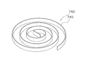
- the load member may include at least one spiral leaf spring.
- the leaf spring is formed by cutting out a thin metal plate and has a central portion where the lower end portion of the operation rod is disposed.
- the spiral leaf spring can be easily processed at the outer peripheral portion and the central portion, and can be processed with high accuracy. For this reason, it is possible to easily and accurately create a load member with reduced direction dependency.
- the leaf spring may further include an outer peripheral part disposed on the outer peripheral side of the central part, and a spiral part having a first end connected to the central part and a second end connected to the outer peripheral part. Thereby, a spiral part is arrange
- the load member may include a plurality of leaf springs arranged one above the other, and the plurality of leaf springs may be arranged with a phase in a rotational direction of a spiral portion of at least one leaf spring shifted.
- the load member may have an even number of leaf springs, and may be alternately overlapped with the front and back reversed by half of the leaf springs and the remaining half of the leaf springs.
- the tilt operation vector can be detected with high accuracy while suppressing the direction dependency of the load member.
- the load member has four leaf springs, and the two leaf springs and the remaining two leaf springs are reversed so that they are preferably alternately stacked and arranged in the same direction.
- the plate springs may be arranged with a phase shifted by 180 degrees. As a result, four types of leaf springs with different front and back surfaces and phases are arranged in an overlapping manner, and the tilt operation vector can be detected with high accuracy while further suppressing the direction dependency of the load member.
- the upper limb training apparatus may further include a plurality of spacers, preferably made of a thin metal plate, arranged between a plurality of leaf springs arranged one above the other. Thereby, interference between leaf springs can be avoided, and the influence of friction can be eliminated. For this reason, the tilting operation vector can be detected with higher accuracy.
- the spacer may have the same shape as the outer peripheral portion. As a result, a smooth appearance can be obtained even if the outer peripheral portion of the leaf spring and the spacer are arranged in an overlapping manner, and the load member can be easily used as a stopper member in the tilting direction of the operating rod.
- the outer peripheral portion may be a perfect circle.
- the spiral portion may have a plurality of arc portions having different radii arranged concentrically, and a connecting portion that connects the arc portion on the inner peripheral side and the arc portion on the outer peripheral side. Since the arc portion has little direction dependency, the above-described structure can reduce the direction dependency of the spiral portion.
- the connecting portion may be arranged so as to be biased within a predetermined angle range. Although the connection part is highly directional-dependent, it is arranged in a predetermined angle range. Therefore, by arranging the connection part by changing the phase, it is possible to cancel the direction dependency due to the connection part.
- the arc portion may occupy a 3/4 angle range of the spiral portion. As a result, since the arc portion occupies a large area of the spiral portion, the direction dependency of the spiral portion is reduced.
- the width of the spiral portion may be constant. Thereby, regardless of the tilting direction, the spiral portion is likely to generate a predetermined elastic resistance force with respect to the tilting amount.
- the plurality of leaf springs may be collectively attached to the frame. Thereby, attachment and detachment of a load member are easy.
- the load member may be a spiral spring formed by winding a metal wire.
- the spiral spring made of metal wire is easy to process.
- the load member may be a mainspring spring formed by spirally processing a metal strip.
- the metal spring spring is easy to process.
- the load member may be a disc-shaped rubber member in which wrinkles are formed concentrically. The rubber member is easy to process and can be manufactured at low cost.
- the vector detection unit suppresses the tilt operation force and the direction dependency of the load member.
- a tilt operation vector including the tilt direction can be detected. For this reason, even if the operating rod is tilted in any direction, the tilting operation vector of the person receiving training can be detected with high accuracy.
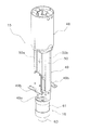
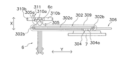
- the perspective view of the upper limb training apparatus as one embodiment of the present invention.
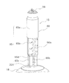
- the perspective view of an upper limb training apparatus The schematic sectional drawing of a training device main part.
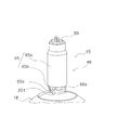
- the schematic sectional drawing of a training device main part The perspective view inside a training device main part.
- Sectional drawing of a training apparatus main body The perspective view inside a training device main part.
- the perspective view inside a training device main part The perspective view inside a training device main part.
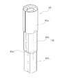
- the perspective view of an operation rod The perspective view of a movable stay.
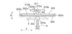
- the schematic plan view for demonstrating the positional relationship of a monitor, a monitor arm, and a monitor rod The schematic plan view for demonstrating the positional relationship of a monitor, a monitor arm, and a monitor rod.
- the schematic plan view for demonstrating the positional relationship of a monitor, a monitor arm, and a monitor rod The schematic plan view for demonstrating the positional relationship of a monitor, a monitor arm, and a monitor rod.
- the side view of a monitor arm. The top view of an upper limb training apparatus.
- the perspective view of a coupling tool The perspective view of a connection part. Sectional drawing of a connection part.
- the perspective view of a remote control The side view of a remote control.
- the perspective view of the load member of other embodiment Furthermore, the perspective view of the load member of other embodiment.
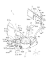
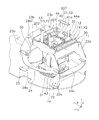
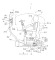
- the upper limb training apparatus 1 has impaired motor function of the upper limb (particularly the arm) due to cerebrovascular disorders and spinal cord injury. It has a function to support recovery of upper limb motor function to perform recovery training of the upper limb for the patient T.
- the upper limb training apparatus 1 includes a training apparatus main body 3, a chair 4, a connection mechanism 5 that connects the training apparatus main body 3 and the chair 4, a monitor stand 6 that is fixed to the training apparatus main body 3 and the monitor 7 is fixed, It has.
- the front-rear direction is the X direction in FIG. 1
- the left-right direction is the Y direction in FIG. 1
- the up-down direction is the Z direction in FIG.
- the front-rear and left-right directions are defined, and the front may be represented as the back side and the rear as the front side.
- the operation rod 15 tilts as will be described later, here, the direction when the operation rod 15 is oriented vertically upward with respect to the floor surface is defined as the Z direction, and on the plane perpendicular to the Z direction.
- X direction and Y direction are defined.
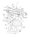
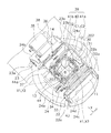
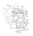
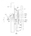
- the training apparatus body 3 includes a frame 10 having a fixed frame 11 and a movable frame 12, a tilting resistance applying mechanism 13, a tilting operation force detecting mechanism 14, and An operation rod 15, an expansion / contraction resistance applying mechanism 16, an expansion / contraction operation force detection mechanism 17, and an exterior cover 18 are provided.
- the fixed frame 11 can be arranged on the floor surface FL.
- the movable frame 12 is supported by the fixed frame 11 so as to be tiltable in all directions including the front-rear X direction and the left-right Y direction from the first tilt center C1.
- the tilting resistance applying mechanism 13 applies an appropriate resistance according to the patient T when the patient T tilts the operating rod 15, or the operating rod 15 is moved to the first tilting center.
- This is a mechanism for assisting the tilting operation of the operation rod 15 by the patient T by guiding the C1 to pivot back and forth and to the left and right or guiding the arm T by the patient T.
- the tilt operation force detection mechanism 14 is a mechanism for detecting an operation force applied to the operation rod 15 by the tilt operation of the patient T and a tilt operation vector indicating the direction of the operation force.
- the operation rod 15 is a rod operated by the patient T for functional recovery training of the upper limbs.
- the operating rod 15 is attached to the movable frame 12 and can be expanded and contracted in the vertical Z direction.
- the tilt operation force detection mechanism 14 is a mechanism for detecting a displacement amount of the operation rod 15 relative to the movable frame 12 by the patient T.
- the expansion / contraction resistance applying mechanism 16 provides an appropriate resistance corresponding to the patient T when the patient T performs the expansion / contraction operation of the operation rod 15, or supports the expansion / contraction operation of the operation rod 15 by the patient T by extending / contracting the operation rod 15. Or a mechanism for guiding the vertical movement of the arm by the patient T.
- the expansion / contraction resistance applying mechanism 16 also functions as an expansion / contraction drive unit that drives the operation rod 15 to expand and contract when the vertical position of the operation rod 15 is adjusted according to the patient T.
- the expansion / contraction operation force detection mechanism 17 is a mechanism for detecting the operation force in the vertical Z direction applied to the operation rod 15 by the vertical movement of the patient's T arm.
- the exterior cover 18 is a cover that covers the periphery of the fixed frame 11 and the movable frame 12.
- the fixed frame 11 is fixed to the base frame 21 that can move the floor surface FL or can be fixedly installed on the floor surface FL. And a first support bracket 22 and a second support bracket 23.
- the base frame 21 is a plate-like frame having a substantially semicircular rear portion (the lower right end portion in FIG. 5).
- One free wheel 21a with casters is arranged on the lower surface of the rear part of the base frame 21, and a pair of fixed wheels 21b arranged at intervals in the left-right direction are arranged on the lower surface of the front part.
- a pair of fixing adjusters 21c for disposing the training apparatus main body 3 so as to be immovable on the floor surface FL are disposed on both sides of the center portion in the front-rear direction of the base frame 21.
- a stand fixing part 21d to which the lower end of the monitor stand 6 is fixed is arranged in the center of the front part of the base frame 21.
- a stand support plate 25 is disposed above the front portion of the base frame 21 so as to extend in the left-right direction in parallel with the stand fixing portion 21d.
- the stand support plate 25 is fixed by a pair of fixing brackets 26 whose left and right ends are raised and fixed to the base frame 21. As shown in FIG.
- the stand support plate 25 has a stand support hole 25a that supports the base end portion 6a of the monitor stand 6 in a non-rotatable manner at the center. Further, the distal end of the base end portion 6 a of the monitor stand 6 is fixed so as not to rotate in a hole (not shown) formed in the stand fixing portion 21 d of the base frame 21. As described above, since the base end portion 6a of the monitor stand 6 is supported by the base frame 21 and the stand support plate 25 so as not to move at the upper and lower portions, the monitor stand is not easily displaced in the radial direction or the tilt direction.
- the posture of the monitor stand 6 with respect to the base frame 21 is maintained firmly. That is, the mounting strength of the monitor stand 6 is high, and it is difficult for a problem that the monitor stand 6 wobbles with respect to the mounting portion. Since the monitor stand 6 also functions as a part of the carry handle as will be described later, it is important that the mounting strength is improved as described above.
- the 1st support bracket 22 and the 2nd support bracket 23 are arrange
- the first support bracket 22 and the second support bracket 23 are formed by bending a steel plate, for example, and support the movable frame 12 at both ends in a tiltable manner.
- the first support bracket 22 is fixed to the rear portion (front side) of the base frame 21.
- the first support bracket 22 has a pair of left and right first fixed portions 22a and a first support portion 22b that connects the pair of first fixed portions 22a at the top.
- the first fixed portion 22 a is formed by bending both ends of the first support portion 22 b and is fixed to the base frame 21.
- the second support bracket 23 is fixed to the base frame 21 at a position facing the front of the first support bracket 22.
- the 2nd support bracket 23 is the structure substantially the same as the 1st support bracket 22, and has a pair of 2nd fixing
- the first support bracket 22 and the second support bracket 23 are reinforced by a reinforcing member 24.
- the reinforcing member 24 is a plate-like member having a D shape in plan view.
- the reinforcing member 24 constitutes a part of the tilt range regulating mechanism 20 that structurally regulates the tilt range of the operation rod 15.
- the tilt range restriction mechanism 20 will be described later.
- the reinforcing member 24 includes a pair of first reinforcing portions 24a that connect both outer surfaces of the first fixing portion 22a and the second fixing portion 23a, a second reinforcing portion 24b that connects the inner surface of the second fixing portion 23a, and a first And a third reinforcing portion 24c that connects the inner surface of the fixed portion 22a.
- a pair of 1st reinforcement part 24a and 2nd reinforcement part 24b are the members of the circular arc shape by planar view formed integrally.
- the pair of first reinforcing portions 24a is a line-symmetric member.
- the end surfaces on the inner peripheral side of the pair of first reinforcing portion 24a and second reinforcing portion 24b are formed in an arc shape.
- the 3rd reinforcement part 24c has connected between the inner surfaces of the 1st fixing
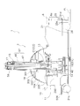
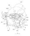
- the movable frame 12 has a first gimbal mechanism 30 as shown in FIGS.
- the first gimbal mechanism 30 includes a first movable part 31 that is rotatably attached to the fixed frame 11 and a second movable part 32 that is rotatably attached to the first movable part 31. .
- the first movable portion 31 is a plate-like member formed in a substantially rectangular frame shape formed by bending a steel plate at four locations.
- the first movable portion 31 is supported at both ends by the first support bracket 22 and the second support bracket 23 so as to be rotatable about an axis in the front-rear X direction.
- the second movable part 32 is a member made of a steel plate that is disposed inside the first movable part 31 and is bent into a rectangular frame shape smaller than the first movable part 31.
- the second movable part 32 is supported at both ends by the first movable part 31 so as to be rotatable about an axis in the left-right Y direction.
- the position where the first movable portion 31 is pivotally supported and the position where the second movable portion 32 is pivotally supported are the same vertical Z-direction position. Therefore, the rotation axis X1 of the first movable part 31 and the rotation axis Y1 of the second movable part 32 are arranged orthogonally. The intersection of the rotation axis X1 and the rotation axis Y1 is the first tilt center C1.
- the tilt resistance imparting mechanism 13 includes an electric X-axis motor 35 for rotationally driving the outer first movable portion 31, and an X-axis. And an X-axis reduction mechanism 36 that transmits the rotation of the output shaft of the motor 35 at a reduced speed.
- the tilting resistance imparting mechanism 13 transmits an electric Y-axis motor 33 for rotationally driving the inner second movable portion 32 and the rotation of the output shaft of the Y-axis motor 33 to reduce and transmit it. And further.
- the X-axis motor 35 and the X-axis reduction mechanism 36 are fixed to the second support bracket 23, for example.
- the X-axis speed reduction mechanism 36 is connected to the first movable part 31 and transmits the rotation of the output shaft of the X-axis motor 35 to the first movable part 31 with a reduction ratio of about 1/60.
- the X-axis motor 35 is disposed at a position close to the floor surface FL in the up-down Z direction with the X-axis reduction mechanism 36, and is connected to the X-axis reduction mechanism 36 by a toothed belt (not shown).
- the Y-axis motor 33 and the Y-axis speed reduction mechanism 34 are fixed to, for example, the outer first movable part 31.
- the Y-axis reduction mechanism 34 is connected to the second movable part 32, and transmits the rotation of the output shaft of the Y-axis motor 33 to the second movable part 32 with a reduction ratio of about 1/60.
- the Y-axis motor 33 is disposed at a position closer to the floor surface FL in the up-down Z direction than the Y-axis reduction mechanism 34 and is connected to the Y-axis reduction mechanism 34 by a toothed belt (not shown).
- the tilting amount of the operating rod 15 includes at least one of the angular position and the angular displacement calculated based on the outputs of the X-axis rotary encoder 37 and the Y-axis rotary encoder 38 and the rotation direction.
- the tilt resistance applying mechanism 13 drives and controls at least one of the angular position and the amount of angular displacement of the X-axis motor 33 and the Y-axis motor 35 and the rotation direction according to the operation force of the patient T detected by the tilt operation force detection mechanism 14. To provide resistance to the operating rod 15.
- the X-axis motor 33 and the Y-axis motor 35 are disposed below the first tilt center C1.
- the tilt operation force detection mechanism 14 is disposed between the movable frame 12 of the frame 10 and the operation rod 15, as shown in FIGS.
- the tilt operation force detection mechanism 14 includes tilt operation forces and tilt directions in all directions from the first tilt center C1 including the front-rear X direction and the left-right Y direction applied to the operation rod 15 by the tilt operation of the patient T as described above.
- This is a mechanism for detecting a tilt operation vector. That is, the tilt operation force detection mechanism 14 detects the direction of the operation force of the patient T when the operation rod 15 is tilted and the magnitude of the operation force.
- the tilt operation force detection mechanism 14 includes a load member 42 and a vector detection unit 39.
- the vector detection unit 39 detects the tilting operation force acting on the operation rod 15 by the displacement of the load member 42 and the tilting direction of the operation rod 15.
- the vector detection unit 39 includes a second gimbal mechanism 40, an X-axis potentiometer 41b, and a Y-axis potentiometer 41a.
- the load member 42 is displaced according to the operating force and the tilting direction.
- the load member 42 is displaced by generating a predetermined elastic resistance force corresponding to the tilting amount regardless of the tilting direction.
- This displacement is detected by the vector detection unit 39, and a tilting operation vector including the tilting direction and tilting operation force of the patient T is detected.
- the vector detecting unit 39 suppresses the direction dependency of the load member and the tilt detection force and tilt.
- a tilt operation vector including a direction can be detected. For this reason, the tilting operation vector of the patient T can be detected with high accuracy regardless of which direction the operating rod 15 is tilted. Using this detection result, for example, an appropriate load can be applied to the patient T to train the upper limb of the patient T.
- the second gimbal mechanism 40 is supported by the movable frame 12 so as to be tiltable in all directions from the second tilt center C2.
- the second gimbal mechanism 40 includes a third movable part 43 that is rotatably attached to the second movable part 32, and a fourth movable part 44 that is rotatably attached to the third movable part 43. ing.
- the third movable part 43 is connected to the second movable part 32 so as to be rotatable about an axis in the front-rear X direction.
- the third movable portion 43 is a steel plate member that is disposed inside the second movable portion 32 and is bent into a rectangular frame shape smaller than the second movable portion 32.
- the fourth movable portion 44 is connected to the third movable portion 43 so as to be rotatable about the axis in the left-right Y direction.
- the fourth movable portion 44 is a member made of a steel plate that is disposed inside the third movable portion 43 and is formed by being bent into a rectangular frame shape smaller than the third movable portion 43.
- Four rod fixing portions 44a for fixing the operation rod 15 are formed on the upper portion of the fourth movable portion 44 by bending them into two opposing pieces.
- the position where the third movable part 43 is rotatably supported and the position where the fourth movable part 44 is rotatably supported are the same vertical Z-direction position. Therefore, the rotation axis X2 of the third movable part 43 and the rotation axis Y2 of the fourth movable part 44 are arranged orthogonally. Further, in this embodiment, when the operating rod 15 is directed upward without being tilted, in the first gimbal mechanism 30 and the second gimbal mechanism 40, the rotation axis X1 and the rotation axis X2 are on the same line. The rotation axis Y1 and the rotation axis Y2 are arranged on the same line.
- the support positions of the first gimbal mechanism 30 and the second gimbal mechanism 40 are at the same height position in the vertical Z-axis direction. That is, the position where the movable frame 12 is pivotally supported with respect to the fixed frame 11 and the position where the operation rod 15 is pivotally supported with respect to the movable frame 12 are arranged on the same plane. ing.
- the intersection of the rotation axis X2 and the rotation axis Y2 is the second tilt center C2, and is at the same position as the first tilt center C1.
- the X-axis potentiometer 41b is fixed to the second movable part 32 and detects the amount of rotation around the rotation axis X2 of the third movable part 43.
- the Y-axis potentiometer 41a is fixed to the third movable part 43 and detects the amount of rotation around the rotation axis Y2 of the fourth movable part 44.
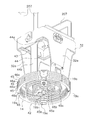
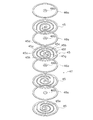
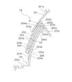
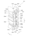
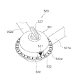
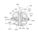
- the load member 42 is displaced by generating a predetermined elastic resistance force corresponding to the amount of tilting of the operation rod 15 regardless of the tilting direction. That is, the load member 42 is a member having a small direction dependency. As shown in FIG. 9, the load member 42 includes a plurality of (for example, four) plates disposed between the second movable portion 32 of the first gimbal mechanism 30 and the fourth movable portion 44 of the second gimbal mechanism 40. A spring 45 is provided. A pair of fixed brackets 32 a and a pair of fixed brackets 44 b for fixing the leaf spring 45 are respectively formed on the second movable part 32 and the fourth movable part 44 so as to extend downward. As shown in FIGS.
- the four leaf springs 45 are each formed by cutting out a thin metal plate and have the same shape.
- a thin metal spacer 46a is arranged between the four leaf springs 45 and in the uppermost layer. Thereby, interference between the leaf springs 45 when the load member 42 is displaced can be avoided, and the leaf spring 45 is likely to displace the central portion 45a relative to the outer peripheral portion 45b. For this reason, the tilting operation vector can be detected with high accuracy.
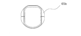
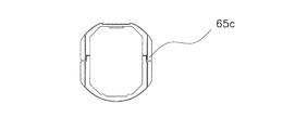
- Each leaf spring 45 has a central part 45a, an outer peripheral part 45b on the outer peripheral side, and a spiral part 45c having one end connected to the central part 45a and the other end connected to the outer peripheral part 45b.
- the lower end portion of the operation rod 15 is disposed at the central portion 45 a of the leaf spring 45, and the spiral portion 45 c is displaced according to the tilting operation force of the operation rod 15.
- the distal end portion of the fixed bracket 44b of the fourth movable portion 44 to which the operation rod 15 is fixed is fixed to the central portion 45a. Since the spiral part 45c is disposed between the outer peripheral part 45b and the central part 45a, the operation rod 15 fixed to the central part 45a is easily deformed with respect to the outer peripheral part 45b.
- the width of the spiral portion 45c is substantially constant. As a result, the spiral portion 45c is likely to generate a predetermined elastic resistance force with respect to the tilt amount regardless of the tilt direction.
- the spacer 46a is a ring-shaped member disposed so as to overlap the outer peripheral portion 45b.
- a washer 46b having the same thickness as the spacer 46a is disposed between the central portions 45a.
- the spiral leaf spring 45 can easily process the outer peripheral portion 45b and the central portion 45a and can perform processing with high accuracy. For this reason, the load member which suppressed direction dependence can be created easily with sufficient accuracy.
- the outer peripheral portion 45b has a perfect circular shape, and the spacer 46a and the outer peripheral surface have the same shape. Therefore, when the four leaf springs 45 and the four spacers are arranged so as to overlap each other, the outer peripheral surface of the load member 42 is arranged in a circular shape. As a result, a smooth appearance can be obtained even if the outer peripheral portion of the leaf spring 45 and the spacer 46a are overlapped, and the load member 42 can be easily used as a tilt limiting member (described later) in the tilt direction of the operating rod 15. .
- the load member 42 functions as a tilt limiting member for limiting the tilting range of the operating rod 15 in the tilting range regulating mechanism 20 (see FIG. 7) that mechanically regulates the tilting range of the operating rod 15. Also have. That is, the load member 42, that is, the tilt limiting member contacts the reinforcing member 24, and the tilt range of the operation rod 15 is structurally restricted.
- the spacer 46a and the outer peripheral part 45b of the leaf spring 45 have the same perfect circular shape, even if the load member 42 is used as the tilt limiting member, the spacer 46a tilts with respect to the inner peripheral side end surface of the reinforcing member 24. Regardless of the direction, the load member 42 can be brought into point contact. For this reason, the operation rod 15 can be regulated at substantially the same tilt angle regardless of the tilt direction.
- the outer peripheral portion 45b is fixed to the fixed bracket 32a of the second movable portion 32 by, for example, four bolt members 19a.
- the plurality of leaf springs 45 are attached to the movable frame 12 in a lump.
- the load member 42 can be easily attached and detached.
- the central portion 45a is fixed to the bottom surface of the fixed bracket 44b of the fourth movable portion 44, for example, by one bolt member 19b.
- the lower end part of the operating rod 15 is arrange
- the four leaf springs 45 are arranged with the front and back reversed and 180 degrees out of phase.
- the plate spring 45 in the second stage from the bottom is arranged with a phase difference of 180 degrees with respect to the plate spring 45 arranged in the lowermost stage.
- the second-stage leaf spring 45 from above the upper side is disposed so as to be reversed with respect to the second-stage plate spring 45 from the bottom.
- the uppermost leaf spring 45 is arranged 180 degrees out of phase with respect to the leaf spring 45 of the second step surface from above.
- the spiral part 45c is arranged concentrically with the first arc part 45d having a smaller diameter than the first arc part 45d and a first arc part 45d arranged concentrically with the outer peripheral part 45b.
- Second arc portion 45e Since the first arc portion 45d and the second arc portion 45e have small direction dependency, the direction dependency of the spiral portion 45c can be reduced.
- the spiral part 45c includes a first connection part 45f that connects the outer peripheral part 45b and the first arc part 45d, a second connection part 45g that connects the first arc part 45d and the second arc part 45e, A second arc portion 45e and a third connecting portion 45h for connecting the central portion 45a.
- the first arc portion 45d and the second arc portion 45e occupy an angular range of 3/4 or more of the spiral portion 45c. Since the first arc portion 45d and the second arc portion 45e having a small direction dependency occupy a large area of the spiral portion 45c, the direction dependency of the spiral portion 45c is reduced.
- the first connection part 45f, the second connection part 45g, and the third connection part 45h are arranged so as to be biased in the same predetermined angular range.
- the 1st connection part 45f, the 2nd connection part 45g, and the 3rd connection part 45h are arranged in the angle range between the starting point and the end point of the 1st circular arc part 45d and the 2nd circular arc part 45e. Since the first connection part 45f, the second connection part 45g, and the third connection part 45h having a large direction dependency are arranged in a predetermined angular range, the phase is changed and / or the front and back are reversed. By arranging the first connection part 45f, the second connection part 45g, and the third connection part 45h, it is possible to cancel the direction dependency due to the first connection part 45f, the second connection part 45g, and the third connection part 45h. .
- the load member 42 includes the four leaf springs 45, and the two leaf springs 45 and the remaining two leaf springs 45 are arranged so as to be reversed alternately and overlap each other.
- Two leaf springs 45 arranged in the same direction are arranged with the phase shifted by 180 degrees.
- four types of leaf springs 45 having different front and back surfaces and phases are arranged in an overlapping manner, so that the tilt operation vector can be detected with high accuracy while suppressing the direction dependency of the load member 42.
- the load member can be alternately and alternately placed with the half leaf spring and the remaining half leaf spring reversed.
- the load member can be alternately and alternately placed with the half leaf spring and the remaining half leaf spring reversed.
- the load member is not an even number, if the load member has a plurality of leaf springs, the rotational direction of at least one spiral portion of the leaf spring can be shifted.
- the elastic resistance force differs between the leaf springs arranged out of phase and the leaf springs not displaced, and the tilting operation can be performed with high accuracy while suppressing the direction dependency of the load member.
- a vector can be detected.
- the operation rod 15 is supported by the movable frame 12 so as to be tiltable in the front-rear X direction and the left-right Y direction by the tilt operation force detection mechanism 14.
- the operating rod 15 has an operating rod main body 57 and an attachment mounting portion 59.
- the operation rod main body 57 includes an expansion / contraction mechanism 47 and a rod cover 48 that covers the periphery of the expansion / contraction mechanism 47.
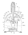
- the telescopic mechanism 47 includes a fixed stay 49, a movable stay 50 that moves up and down relative to the fixed stay 49, a linear guide 51 that linearly guides the movable stay 50, and a movable stay. And an elevating mechanism 52 that raises and lowers 50.
- the fixed stay 49 is attached to the movable frame 12, and more specifically, is fixed from above to the rod fixing portion 44a of the fourth movable portion 44 of the tilting operation force detection mechanism 14 shown in FIGS. . Thereby, the fixed stay 49 can be removed from the second gimbal mechanism 40 with the exterior cover 18 removed. For this reason, the operation rod 15 can be attached to and detached from the movable frame 12, and the operation rod 15 can be exchanged according to the training contents and the training environment or when a failure occurs.
- the fixed stay 49 is a member formed by bending a steel plate so that the cross section has a grooved steel shape.
- An L-shaped fixing bracket 49 b fixed to the rod fixing portion 44 a of the fourth movable portion 44 is fixed to the left and right surfaces on the lower end side of the fixed stay 49.
- a motor support portion 49 a formed by bending 90 degrees is formed below the fixed stay 49.
- a Z-axis motor 61 is fixed to the lower surface of the motor support 49a.
- a guide rail 53 that constitutes the linear guide 51 and is long in the vertical direction is fixed to the inner side surface of the fixed stay 49 (see FIG. 11).
- a ball screw shaft 55 constituting an elevating mechanism 52 extending over the upper and lower ends is rotatably supported at the lower end of the fixed stay 49.
- the movable stay 50 is a member that is disposed inside the fixed stay 49 and is long in the vertical direction.
- the movable stay 50 includes an inner frame member 50a and an outer frame member 50b formed by bending a steel plate so that the cross section has a gate shape (double housing) shape.
- the outer frame member 50b is disposed opposite to the outer surface of the inner frame member 50a so that the movable stay 50 has a rectangular cross section.
- the slide unit 54 guided by the guide rail 53 is fixed to the block 50d below the inner frame member 50a.
- the inner frame member 50a holds the slide unit 54 with the block 50d and the slide unit 54 sandwiched from both sides.
- the slide unit 54 and the guide rail 53 constitute a linear guide 51.
- a ball nut 56 constituting the elevating mechanism 52 is fixed to the block 50d, which is a portion where the slide unit 54 is fixed to the inner frame member 50a.
- the ball nut 56 is screwed onto the ball screw shaft 55.
- the movable stay 50 is linearly movable along the fixed stay 49 in the expansion / contraction direction (vertical Z direction).
- the ball nut 56 and the slide unit 54 are attached to the block 50d fixed to the movable stay 50, and the block 50d and the slide unit 54 are attached to the movable stay 50 so as to be sandwiched from both sides. Further, the ball screw shaft 55 and the guide rail 53 are attached to the fixed stay 49. For this reason, the slide unit 54 and the ball nut 56 are less likely to be misaligned with respect to the movable stay 50, and the strength of the fixed stay 49 can be improved.
- the lower end portion 50c of the inner frame member 50a is a detected portion 58 having a detected piece 58a that hangs downward.
- the detected part 58 is provided for detecting the lower end position of the movable stay 50 detected by the lower end position detecting part 60.
- the lower end position detection unit 60 is, for example, a light emitting / receiving photoelectric sensor (photo interrupter) 60 a fixed to the fixed stay 49.
- the photoelectric sensor 60a detects the lower end position of the movable stay 50 by blocking the opened optical path by the detected piece 58a.
- the lower end position of the movable stay 50 can be arranged as low as possible.
- the lower end position detecting unit 60 that requires wiring for sending a signal is fixed to the fixed stay 49, the wiring is difficult to cut even if the operation rod 15 expands and contracts.
- the ball screw shaft 55 Only the lower end of the ball screw shaft 55 is rotatably supported on the fixed stay 49 by a bearing. A lower end portion of the ball screw shaft 55 is coupled to an output shaft 61 a of an electric Z-axis motor 61 through a coupling 62 so as to be integrally rotatable.
- the output shaft 61a and the ball screw shaft 55 are arranged concentrically.
- the tilting range of the operating rod 15 is limited by the control based on the moving range regulation program and the tilting range regulation mechanism 20.
- Control based on the movement range regulation program is executed by the storage unit 100 and the control unit 110 included in the training apparatus body 3 as shown in FIG.
- the storage unit 100 stores various data.
- the storage unit 100 temporarily and / or long-term stores various programs, various parameters, various data, data being processed, and the like.
- the storage unit 100 includes a ROM (Read Only Memory) and a RAM (Random Access Memory).
- the control unit 110 issues control signals to various mechanisms and controls the various mechanisms.
- the control unit 110 executes various determination processes, and controls various mechanisms based on the determination results.
- the control unit 110 reads various programs related to control and calculation from the storage unit 100 to execute various controls, various determination processes, and various calculations, and controls various mechanisms.
- the control unit 110 includes, for example, a CPU (Central Processing Unit).
- the control unit 110 is connected to the storage unit 100 via the bus 115.
- the movement range restriction program is for restricting the movable range of the movable frame 12 and is stored in the storage unit 100.
- the control unit 110 controls the operation of the movable frame 12 based on the movement range restriction program.
- the movement range regulation program includes a detection unit 111 that detects the operation of the movable frame 12, a calculation unit 112 that calculates a state angle h that indicates the tilting state of the movable frame 12, and the state of the movable frame 12.
- a monitoring unit 113 that monitors whether the angle h exceeds a predetermined angle, and an operation stop unit 114 that stops the operation of the movable frame 12 when the state angle h of the movable frame 12 exceeds a predetermined angle.
- the above state angle h corresponds to the angle formed by the axis (Z axis) perpendicular to the floor surface and the axis of the operating rod 15 with respect to the first tilt center C1. That is, the state angle h corresponds to an angle obtained by combining the tilt angle ⁇ x around the X axis and the tilt angle ⁇ y around the Y axis.
- the detection unit 111 detects the operation of the movable frame 12 (S1). More specifically, the detection unit 111 detects the outputs of the X-axis rotary encoder 37 and the Y-axis rotary encoder 38. Then, the calculation unit 112 calculates the state angle h and the maximum of the movable frame 12 based on the outputs of the X-axis rotary encoder 37 and the Y-axis rotary encoder 38, for example, the tilt angle ⁇ x about the X axis and the tilt angle ⁇ y about the Y axis. The state angle h is calculated at predetermined time intervals (S2).
- the maximum state angle H is the maximum value of the state angle h permitted in the control based on the movement range restriction program.
- the maximum state angle H is set to an appropriate value by comprehensively considering the safety and effect of training.
- the monitoring unit 113 constantly monitors whether or not the state angle h of the movable frame 12 exceeds the maximum state angle H (S3), and the state angle h of the movable frame 12 exceeds the maximum state angle H.
- the operation stop unit 114 issues a drive stop command to the tilting resistance applying mechanism 13.
- the tilting resistance imparting mechanism 13 stops its operation, and the movable frame 12, that is, the operating rod 15, becomes unable to move to a range exceeding the maximum state angle H (S4).
- the tilt range of the operation rod 15 (second tilt range described later). Is set. Thereby, even if the patient T operates the operation rod 15 in any direction, the operation rod 15 cannot move beyond the predetermined tilting range, so that the patient T is less likely to slide off the chair 4 and the patient T T safety can be secured.
- the tilting range in which the operating rod 15 can be structurally operated is a tilting range in which the operating rod 15 can be operated in a state where the movable frame 12 is controlled based on the movement range regulation program.
- the first tilt range is set to a tilt range that is, for example, about 3 degrees larger than the second tilt range.
- the second tilt range is smaller than the first tilt range. That is, the maximum state angle H is set so that the second tilt range is smaller than the first tilt range.
- the maximum state angle H is set so that the second tilt range is smaller than the first tilt range by, for example, about 10 degrees.
- the tilting range restriction mechanism 20 includes a stopper portion 24d for restricting the tilting of the operating rod 15, and a load member 42 (tilting restriction member) that contacts the stopper portion 24d.
- the stopper portion 24d is an end surface on the inner peripheral side of the reinforcing members 24a to 24c.
- the operating rod 15 tilts and the load member 42 contacts the stopper portion 24d as a tilt limiting member, so that the tilting range of the operating rod 15 is structurally limited.
- the shape and range of the end surface on the inner peripheral side of the reinforcing member 24 c are formed so that the operating rod 15 does not interfere with the monitor 7.
- the stopper 24d that is, the end surface on the inner peripheral side of the reinforcing member 24 is formed in a D shape in plan view.
- the maximum movable range 320 of the load member 42 when the load member 42 moves along the end surface on the inner peripheral side of the reinforcing member 24 also has a D shape in plan view (see FIG. 27).
- the first tilt range is larger than the second tilt range
- the first maximum movable range of the end portion of the operating rod 15 limited by the stopper portion 24d is controlled based on the moving range regulation program. It is larger than the second maximum movable range at the end of the operating rod 15.
- the second maximum movable range is set in correspondence with the movable range of the movable frame 12 controlled based on the movement range restriction program.
- a part of the stopper portion 24d for example, the third reinforcing portion 24c of the reinforcing member 24 determines the maximum inclination of the operating rod 15 forward (back side, left side in FIG. 27) when viewed from the patient T. It is a part to do.
- the 3rd reinforcement part 24c restrict
- the third reinforcing portion 24c is provided at a position lower than the first reinforcing portion 24a and the second reinforcing portion 24b, and the inner peripheral portion protrudes toward the first tilting center C1.
- the inclination angle of the operation rod 15 when the load member 42 contacts the inner peripheral surface of the protruding portion of the third reinforcing portion 24c is such that the load member 42 has the inner peripheral surface of the first reinforcing portion 24a and the second reinforcing surface. It becomes smaller than the inclination angle of the operating rod 15 when it contacts the inner peripheral surface of the portion 24b.
- the absolute value of the difference between the inclination angles is set to about 10 degrees, for example.
- the movable frame 12 operates according to the tilt of the operation rod 15. Then, the state angle h of the movable frame 12 is calculated.
- the tilting resistance applying mechanism 13 stops its operation, and the operation rod 15 cannot move to the tilt range exceeding the maximum state angle H.
- the operation rod 15 is finally restricted by the tilt range restriction mechanism 20. Specifically, the operation rod 15 becomes inoperable when the operation rod 15 contacts the stopper portion 24d.
- the control unit 110 restricts the movable range of the movable frame 12 and restricts the tilting range of the operation rod 15. Is controlling. For this reason, even if the patient T has operated the operation rod 15 larger than necessary, the operation rod 15 cannot operate outside the range in which the patient T can safely operate. As described above, in the upper limb training apparatus 1, the movable range of the movable frame 12 is limited by the control unit 110 so that the patient T can safely train.
- the stopper portion 24d determines the maximum forward tilt of the operation rod 15 as viewed from the patient T. For this reason, even if the patient T has operated the operation rod 15 largely forwards more than necessary, the patient T can safely train without falling forward.
- the linear portion of the stopper portion 24d is provided lower than the other portion of the stopper portion 24d on the floor surface side, so that the maximum inclination of the operation rod 15 forward is achieved. Is set smaller. Thereby, even if the patient T has operated the operation rod 15 forward (back side) more than necessary, the operation rod 15 cannot move forward (back side) larger than the maximum inclination. Patient T can be safely trained.
- the maximum movable range of the end portion of the operating rod 15 is D-shaped in plan view. For this reason, for example, when the D-shaped linear portion is set as a portion that restricts the forward movement (back side) of the operation rod 15, the forward movement of the operation rod 15 is uniformly restricted at the same position.
- the Furthermore, the right and left and rear (front side) restrictions of the operating rod 15 are formed along the curve of the stopper portion 24d.
- the tilting range of the operation rod 15 is further limited by the moving range restricting mechanism 20 after being restricted based on the moving range restricting program. That is, when the patient T operates the operation rod 15, first, the tilt range of the operation rod 15 is limited by software based on the movement range restriction program, and then the tilt of the operation rod 15 is tilted by the tilt range restriction mechanism 20.
- the range is structurally limited. Thereby, even when the patient T suddenly operates the operation rod 15 and the control by the movement range restriction program cannot follow, the movement of the operation rod 15 can be reliably restricted by the tilt range restriction mechanism 20.
- the maximum movable range to the front (back side) of the movable frame 12 is also set so that the operation rod 15 does not interfere with the monitor. Even if the operation is performed more than necessary, there is no possibility that the hand of the patient T collides with the monitor.
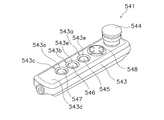
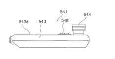
- each attachment AT has a plurality of contact terminals 159 as shown in FIG.
- the outer shape of the bottom surface side of the attachment AT is indicated by a two-dot chain line, and a plurality of contact terminals 159 provided on the bottom surface are indicated by solid lines.
- Each contact terminal 159 corresponds to each of a plurality of pin terminals 84a described later. That is, the plurality of contact terminals 159 are provided in the attachment AT so that the contact terminals 159 and the pin terminals 84a corresponding to the contact terminals 159 can contact each other.
- each of the plurality of attachments AT two predetermined contact terminals 159 among the plurality of contact terminals 159 are short-circuited.
- the combination of the two contact terminals 159 that are short-circuited in each of the plurality of attachments AT is different. That is, the plurality of contact terminals 159 are provided in each attachment AT so that the pattern (short circuit pattern) in which the two contact terminals 159 are short-circuited in each of the plurality of attachments AT is different.
- FIG. 23 shows a state in which the contact terminals 159 adjacent to the center contact terminal 159 in each row are short-circuited to each other.
- the attachment attachment portion 59 is for detachably attaching the attachment AT corresponding to the training program for the patient T, and is attached to the upper end portion of the movable stay 50.
- the expansion / contraction operation force detection mechanism 17 is attached to the attachment attachment portion 59.
- the attachment attachment portion 59 includes an attachment member 70 attached to the movable stay 50, an axial movement permission member 80 attached to the attachment member 70 so as to be movable in the axial direction, and an attachment member.
- a plurality of positioning members 95 for positioning, and a reference member 88 serving as a reference when detecting an operation force in the vertical Z direction applied to the operation rod 15 in the expansion / contraction operation force detection mechanism 17 are provided.
- the mounting member 70 has a stay mounting portion 71 mounted on the movable stay 50 and a shaft portion 72 provided on the stay mounting portion 71.
- the stay mounting portion 71 includes a disc portion 71a formed in a disc shape, and a pair of rectangular plate portions 71b (see FIGS. 23 and 24) that are integrally formed to protrude downward from the surface of the disc portion 71a. Only one is displayed).
- the disc portion 71a has a through hole 71c formed at the center.
- the pair of rectangular plate portions 71b are formed to face each other.
- Each rectangular plate portion 71 b is formed with a plurality of bolt holes, for example, four bolt holes, and the movable stay 50 is also formed with bolt holes corresponding to the bolt holes.
- the mounting member 70 is mounted on the movable stay 50 by inserting a bolt member into the bolt hole of each rectangular plate portion 71 b and the bolt hole of the movable stay 50 and screwing a nut member into the bolt member.
- the shaft portion 72 includes a shaft portion main body 72a formed in a cylindrical shape, and a flange portion 72b for the shaft portion integrally formed on the outer periphery on the lower end side of the shaft portion main body 72a.
- the shaft movement permission member 80 has a cylindrical portion 81 that is slidably mounted on the shaft portion 72 and an exterior portion 82 that covers the cylindrical portion 81.
- the cylindrical portion 81 has an annular groove portion 81a formed on the lower end side, a first flange portion 81b for the cylindrical portion formed on the upper end side, and a predetermined portion on one end side from the first flange portion 81b for the cylindrical portion.
- the second flange portion 81c for the cylindrical portion formed with an interval of and the step portion 81d formed on the inner peripheral surface.
- the exterior portion 82 includes an exterior portion main body 83, a terminal attachment member 84 to which a terminal for identifying the type of the attachment AT is attached, a cover member 85, and a plurality of pin members 86 for attaching the attachment AT. is doing.
- the exterior body 83 is formed in a circular shape in plan view.
- the exterior portion main body 83 includes a concave circular first step portion 83a, a second step portion 83b formed to be recessed with a smaller diameter than the first step portion 83a at the bottom center of the first step portion 83a, and a second step. And a through hole 83c formed in the center of the bottom of the portion 83b.
- the first flange portion 81b of the shaft movement permission member 80 is fitted to the second step portion 83b. More specifically, the outer peripheral surface of the first flange portion 81b of the shaft movement permission member 80 is fitted to the wall portion of the second step portion 83b, and the shaft movement permission member is disposed to the bottom of the second step portion 83b. The surface on the end side of the first first flange portion 81b of 80 is brought into contact.
- the terminal mounting member 84 is formed in a circular shape in plan view.
- a plurality of terminals 84a for example, ten pin terminals are mounted on the terminal mounting member 84 in such a manner that their contact portions are exposed upward.
- the cord extending from each of the plurality of pin terminals 84 a passes through the inside of the terminal mounting member 84 and extends below the terminal mounting member 84.
- FIG. 24 only a part of the code is shown.
- Such a terminal mounting member 84 is mounted in the through hole 83 c of the exterior body 83. More specifically, the surface of the terminal mounting member 84 opposite to the surface where the pin terminal 84a is exposed faces the end of the shaft movement permission member 80 on the side where the first flange portion 81b is formed.
- the terminal mounting member 84 is fitted into the through hole 83 c of the exterior body 83.
- the cover member 85 is formed in a cylindrical shape having a larger diameter than the exterior body 83. On the opening side above the cover member 85, an annular flange 85a is integrally formed.
- the cover member 85 is attached to the exterior part main body 83 by fitting the inner peripheral surface of the annular flange 85 a to the outer peripheral surface of the exterior part main body 83.
- an annular groove 85 b for mounting the positioning member 95 is formed on the inner peripheral surface of the cover member 85.
- the plurality of pin members 86 are fitted into mounting holes formed in the attachment AT so as to be recessed from the lower surface. As a result, the attachment AT is attached to the exterior portion 82, that is, the attachment attachment portion 59.
- a plurality of pin members 86 for example, two pin members are attached to the exterior body 83.
- the sliding bearing 90 is for sliding the shaft movement permission member 80 with respect to the mounting member 70.
- the slide bearing 90 is disposed between the shaft portion 72 of the mounting member 70 and the cylindrical portion 81 of the shaft movement permission member 80. More specifically, the slide bearing 90 is formed in a cylindrical shape, and is fitted into a stepped portion 81 d formed on the inner peripheral surface of the cylindrical portion 81 in the shaft movement permission member 80. In this state, by attaching the inner peripheral surface of the slide bearing 90 to the outer peripheral surface of the shaft portion 72 of the mounting member 70 so as to be slidable, the shaft movement permission member 80 is axially (vertically) with respect to the mounting member 70. It is movable.
- the sliding bearing 90 is a resin bush.
- the plurality of positioning members 95 are for positioning the elastic member 94.
- the plurality of positioning members 95 includes first to fourth positioning members 96, 97, 98, and 99.
- the first positioning member 96 is an annular plate member and is attached to the annular groove 85 b of the cover member 85.
- the pair of second positioning members 97 are disposed between a plurality of elastic members 94 described later.
- one second positioning member 97a is formed in a cylindrical shape.
- the second positioning member 97a is attached to the inner peripheral surface of the cover member 85. More specifically, the second positioning member 97a is formed by fitting a concave portion formed in the second positioning member 97a to a convex portion (not shown) formed on the inner peripheral surface of the cover member 85, thereby Attached to the inner peripheral surface of the member 85.
- the other second positioning member 97b is formed in a cylindrical shape.
- the cylinder diameter of the other second positioning member 97b is smaller than the cylinder diameter of the second positioning member 97a.
- the second positioning member 97b is attached to the outer peripheral surface of the cylindrical portion 81 of the shaft movement permission member 80.
- the second positioning member 97a disposed on the cover member 85 side is referred to as a second positioning member on the outer peripheral side
- the second positioning member 97b disposed on the tubular portion 81 side of the shaft movement permission member 80 is This is called an inner peripheral second positioning member.
- the pair of third positioning members 98 includes an elastic member 94 (94b) disposed on the lower end side of the cylindrical portion 81, for example, on the annular groove portion 81a side of the cylindrical portion 81, and a stay mounting portion of the mounting member 70. 71.
- one third positioning member 98a is formed in a cylindrical shape.
- the one third positioning member 98 a is attached to the inner peripheral surface of the cover member 85. More specifically, one third positioning member is formed by fitting a concave portion formed on one third positioning member 98a to a convex portion (not shown) formed on the inner peripheral surface of the cover member 85. 98 a is attached to the inner peripheral surface of the cover member 85.
- the other third positioning member 98b is formed in an annular shape.
- the ring diameter of the other third positioning member 98b is smaller than the cylinder diameter of the one third positioning member 98a.
- the other third positioning member 98 b is attached to the outer peripheral surface of the cylindrical portion 81 of the shaft movement permission member 80.
- the other third positioning member 98 b is an axial movement permission member between the elastic member 94 (94 b) disposed on the annular groove 81 a side (lower end side) of the cylindrical portion 81 and the reference member 88. Attached to the outer peripheral surface of 80 cylindrical portions 81.
- positioned at the cover member 85 side is called the 3rd positioning member of an outer peripheral side, and the 3rd positioning member 98 arrange
- the fourth positioning member 99 is attached to the lower end side of the cylindrical portion 81.
- the fourth positioning member 99 is formed in an annular shape and is attached to the outer peripheral surface of the cylindrical portion 81. More specifically, the fourth positioning member 99 is, for example, a C-type retaining ring, and is fitted into the annular groove portion 81 a of the tubular portion 81.
- the reference member 88 is a member that serves as a reference when detecting the operation force in the vertical Z direction applied to the operation rod 15 in the expansion / contraction operation force detection mechanism 17.
- the reference member 88 is in contact with an axial displacement detector 17a of an expansion / contraction operation force detection mechanism 17 described later.
- the reference member 88 is formed in an annular shape.
- the elastic member 94 is for absorbing a force (off-axis force) other than the axial direction with respect to the movable stay 50.
- the elastic member 94 is composed of a plurality of elastic members, and the plurality of elastic members 94 are arranged between the cylindrical portion 81 and the exterior portion 82 at a predetermined interval in the axial direction.
- the elastic member 94 is a spiral spring, for example, a plate-shaped spiral spring.
- the plurality of elastic members 94 includes two plate-like spiral springs 94a and 94b.
- the plate-like spiral springs 94a and 94b are arranged at a predetermined interval in the axial direction, the plate-like spiral springs 94a and 94b can generate a force in a direction intersecting the axial direction. The force at the time of moment generation can be absorbed reliably.
- the two plate-like spiral springs 94a and 94b have the same shape, and are turned upside down and arranged between the tubular portion 81 and the exterior portion 82 at a predetermined interval in the axial direction.
- Each of the two plate-like spiral springs 94 a and 94 b is disposed between the cylindrical portion 81 and the exterior portion 82 via the positioning member 95.
- one (upper) plate-like spiral spring 94a has its outer peripheral edge clamped between the second positioning member 97a and the first positioning member 96 on the outer peripheral side.
- one plate-like spiral spring 94 a has its inner peripheral edge clamped between the second positioning member 97 b on the inner peripheral side and the second flange 81 c of the axial movement permission member 80.
- the other (lower) plate-like spiral spring 94b has its outer peripheral edge clamped between the outer peripheral second positioning member 97a and the outer peripheral third positioning member 98a.
- the other plate-like spiral spring 94b has its inner peripheral edge sandwiched between the inner peripheral second positioning member 97b and the inner peripheral third positioning member 98b.
- the outer peripheral portions of the two plate-like spiral springs 94a and 94b are positioned by the second positioning member 97a on the outer peripheral side and the third positioning member 98a on the outer peripheral side.
- the inner peripheral portions of the two plate-like spiral springs 94a and 94b are positioned by an inner peripheral second positioning member 97b and an inner peripheral third positioning member 98b. Further, the axial movement of the inner peripheral portions of the two plate-like spiral springs 94 a and 94 b is restricted by the fourth positioning member 99 via the adjustment member 89 and the reference member 88.
- the signal receiving unit 184 for identifying a signal unique to the attachment AT in a state where the attachment AT is attached to the attachment mounting unit 59 is included in the control unit 110.
- the signal receiving unit 184 identifies a conduction pattern described later.
- the attachment mounting portion 59 further includes a plurality of pin terminals 84a, and each pin terminal 84a corresponds to each of the plurality of contact terminals 159 described above. That is, the plurality of pin terminals 84a are provided in the attachment mounting portion 59 so that each pin terminal 84a and the contact terminal 159 corresponding to each pin terminal 84a can contact each other. Specifically, the plurality of pin terminals 84a, for example, 10 pin terminals are mounted on the terminal mounting member 84 so as to protrude outward from the upper surface of the terminal mounting member 84.
- ten pin terminals 84 a arranged in two rows with five as one set are provided on the terminal mounting member 84. In this case, when the attachment AT is attached to the attachment attachment portion 59, the ten pin terminals 84a come into contact with the ten contact terminals 159 described above.
- each of the two short-circuited contact terminals 159 and the pin terminal 84a that contacts each of the two contact terminals 159 are connected by a one-dot chain line.
- a signal specific to the attachment AT corresponding to this conduction pattern is identified by the signal receiving unit 184.
- the control part 110 determines the kind of attachment AT based on this signal. And the control part 110 starts an upper limb training program according to the kind of attachment AT determined based on the signal, and controls an upper limb training apparatus based on an upper limb training program.
- the control unit 110 can automatically select the upper limb training program corresponding to the attachment AT.
- the upper limb training apparatus 1 can reliably or automatically select the upper limb training program corresponding to the attachment AT. For this reason, the doctor and the occupational therapist can automatically execute the training program corresponding to the attachment AT only by attaching the attachment AT to the attachment mounting portion 59. Thereby, the patient can perform optimal upper limb training using the attachment AT selected by the doctor and occupational therapist.
- the control unit 110 extracts several upper limb training programs corresponding to the type of the attachment AT and allows the user to select them, or automatically starts one upper limb training program. Since the upper limb training apparatus 1 is controlled, the doctor or occupational therapist can execute the training program corresponding to the attachment AT without mistake by simply attaching the attachment AT to the attachment attachment portion 59. Thereby, the patient can perform optimal upper limb training using the attachment AT selected by the doctor and occupational therapist.
- the rod cover 48 includes a cover structure 65 including a plurality of (for example, three) cover elements that cover the expansion / contraction mechanism 47 and are fitted in a nested structure that expands / contracts with the expansion / contraction mechanism 47.
- the cover element is fitted to the upper cover element 65a, the intermediate cover element 65b fitted to the inner peripheral side of the upper cover element 65a, and the inner peripheral surface of the intermediate cover element 65b.
- a lower cover element 65c is fitted to the upper cover element 65a, the intermediate cover element 65b fitted to the inner peripheral side of the upper cover element 65a, and the inner peripheral surface of the intermediate cover element 65b.
- the upper cover element 65 a is a cover element having the maximum diameter that is fixed to the upper end of the movable stay 50.
- the intermediate cover element 65b is an intermediate diameter cover element that expands and contracts together with the upper cover element 65a.
- the lower cover element 65c is a cover element having a minimum diameter that fits on the inner peripheral side of the intermediate cover element 65b.
- a tapered surface 65d that increases in thickness from the lower end edge upward is formed.
- the upper cover element 65a, the intermediate cover element 65b, and the lower cover element 65c have a structure that can be vertically divided into two as shown in FIGS. 17, 18, 19, and 20, respectively.
- the divided upper cover element 65a is connected to the movable stay 50 by screws.
- the divided intermediate cover element 65b is elastically connected to the upper cover element 65a in a suspended state.
- the divided lower cover element 65 c is elastically connected to the fixed stay 49.
- the upper outer peripheral surface of the intermediate cover element 65b is engaged with the inner peripheral surface of the lower end of the upper cover element 65a.
- a first scale 66a and a second scale 66b for indicating the extension length of the operation rod 15 are written on the outer peripheral surfaces of the lower cover element 65c and the intermediate cover element 65b.
- the first scale 66a of “H1, H2, H3...” Is written on the lower cover element 65c
- the second scale of “L0, L1, L2, L3.
- a scale 66b is shown.
- the upper cover element 65a has a circular cross section.
- the intermediate cover element 65b shown in FIG. 19 and the lower cover element 65c shown in FIG. 20 are non-circular (oval shapes) in which the cross section is formed by linearly cutting the top and the left of the circle.
- the lower cover element 65c has a shape in which the left and right sides are larger than the intermediate cover element 65b.
- the stretch resistance imparting mechanism 16 has the Z-axis motor 61 described above.
- the expansion / contraction resistance applying mechanism 16 drives the Z-axis motor 61 according to the expansion / contraction operation force detected by the expansion / contraction operation force detection mechanism 17 to apply resistance to the expansion / contraction operation of the operation rod 15, and assists or forcibly moves.
- the expansion / contraction resistance applying mechanism 16 also functions as an expansion / contraction drive unit that expands / contracts the operation rod 15 for the purpose of adjusting the training height.
- the Z-axis motor 61 of the expansion / contraction resistance applying mechanism 16 is located below the plane supporting position of the movable frame 12, that is, the plane including the rotation axis X1 and the rotation axis Y1 of the first gimbal mechanism 30 (on the floor surface FL). It is placed in a close position. That is, in the telescopic drive unit, the rotation axis X2 and the rotation axis Y2 of the second gimbal mechanism 40 are also in the same vertical Z-direction position. It is arranged at a position close to the FL. As shown in FIG. 11, the Z-axis motor 61 is provided with a Z-axis rotary encoder 63 for detecting the position in the Z-axis direction.
- the patient T tilts the operation rod 15 using, for example, the attachment AT using the upper limb.
- the operating rod 15 tilts in a state where resistance is applied, assisted, or forcibly moved by the tilt resistance applying mechanism 13.
- the upper limb of the patient T can be trained.
- the Z-axis motor 61 having a relatively large mass for expanding and contracting the operation rod 15 is disposed at a position closer to the floor surface FL than the first tilt center C1 where the movable frame 12 tilts, that is, below, the upper limb training. Since the center of gravity of the apparatus 1 is lowered, the upper limb training apparatus 1 is difficult to fall even if the installation area of the training apparatus body 3 is small. Further, since the center of the moment generated by the tilting of the operating rod 15 can be brought close to the first tilting center C1, the mechanical load can be reduced.
- the operation rod 15 is supported by the movable frame 12 so as to be tiltable in all directions from the second tilt center C2, and the expansion / contraction resistance applying mechanism 16 is disposed at a position closer to the floor surface FL than the second tilt center C2. ing.
- the upper limb training apparatus 1 is more difficult to fall.
- the 1st tilt center C1 and the 2nd tilt center C2 are arrange
- the output shaft 61a of the Z-axis motor 61 extends along the extending / contracting direction of the operation rod 15, and the ball screw shaft 55 of the operation rod 15 is connected to the output shaft 61a by a coupling 62 so as to be concentric with the output shaft 61a. And can be rotated together. Thereby, the heavy object including the Z-axis motor 61 can be disposed only directly below the operation rod 15, and the planar dimension of the upper limb training apparatus 1 can be reduced.
- the telescopic operating force detection mechanism 17 has an axial displacement detector 17a.
- the shaft displacement detector 17 a detects the position of the shaft movement permission member 80 in the axial direction with respect to the mounting member 70.
- the shaft displacement detector 17 a is disposed inside the operation rod 15 and is in contact with the reference member 88 of the mounting member 70.
- the shaft displacement detector 17a includes a linear potentiometer.
- the sensor head 17 b of the linear potentiometer is spring-biased and is always in contact with the lower surface of the reference member 88 fixed to the shaft movement permission member 80. More specifically, the sensor head 17b is set on the lower surface of the reference member 88 in a state where the sensor head 17b of the linear potentiometer 17a is contracted by a predetermined amount against the spring force of the coil spring disposed on the outer periphery of the sensor head 17b. Has been. The position of the sensor head 17b in this state is set to the initial position of the sensor head 17b.
- the sensor head 17b expands and contracts in the axial direction following the movement in the axial direction. Then, the linear potentiometer 17a outputs a voltage value corresponding to the amount of movement of the sensor head 17b with respect to the input reference voltage. Based on this voltage value, a processor (not shown) such as a CPU calculates the amount of movement of the sensor head 17b relative to the initial position of the sensor head. In this way, the shaft displacement detector 17a detects the displacement of the operation rod 15 in the axial direction. The axial displacement of the operating rod 15 takes a positive value or a negative value with reference to the initial position.
- the axial operation force applied to the operation rod 15 is calculated based on the axial displacement of the shaft movement permission member 80.
- a processing unit such as a CPU, generates an axial operation force applied to the operation rod 15 based on a correspondence table of the axial displacement of the axial movement permission member 80 and the axial force corresponding to the axial displacement.
- the correspondence table is set based on the rigidity of the plurality of elastic members 94, for example, the rigidity in the out-of-plane direction of the two plate-like spiral springs 94a and 94b.
- the attachment to which the attachment AT is attached when the patient T places his / her hand or arm on the attachment AT or holds the attachment AT and operates the operation rod 15 in the axial direction, the attachment to which the attachment AT is attached.
- the attachment portion 59 moves in the operation direction (up and down). Specifically, when a force component other than the axial direction is generated in the operating rod 15 when the patient T operates the operating rod 15 in the axial direction, the force component is absorbed by the elastic member 94. Then, the axial movement permission member 80 moves in the axial direction with respect to the mounting member 70 via the slide bearing 90 by the axial force generated in the operation rod 15.
- the reference member 88 fixed to the shaft movement permission member 80 also moves in the axial direction at the same time, and the sensor head in contact with the reference member 88 expands and contracts. Then, the expansion / contraction operation force detection mechanism 17 detects an axial force corresponding to the expansion / contraction amount of the sensor head, that is, an axial operation force applied to the operation rod 15.
- the axial displacement detection unit 17a detects an axial displacement corresponding to the axial force applied to the operation rod 15.
- the axial displacement detection unit 17 a absorbs the axial force acting on the operation rod 15 by the two plate-like spiral springs 94 a and 94 b while the axial displacement detection unit 17 a is in the axial direction. Since the displacement can be detected, the force acting only in the axial direction of the operating rod 15 can be accurately obtained.
- the shaft displacement detector 17a is disposed inside the operation rod 15, unnecessary external force such as impact force does not directly act on the shaft displacement detector 17a. Thereby, only the displacement (axial displacement) of the measurement object of the axial displacement detector 17a can be measured more accurately.
- the shaft displacement detector 17a is, for example, a linear potentiometer
- the shaft of the shaft movement permission member 80 relative to the mounting member 70 is brought into contact with the shaft movement permission member 80 by bringing the sensor head 17b of the linear potentiometer 17a into contact with the shaft movement permission member 80.
- the position in the direction can be detected more accurately.
- the two plate-like spiral springs 94 a and 94 b are arranged in the axial direction between the cylindrical portion 81 of the shaft movement permission member 80 and the exterior portion 82 of the shaft movement permission member 80. Since they are arranged at a predetermined interval, it is possible to reliably absorb forces other than the axial direction that can directly act on the operating rod 15, forces other than the axial direction when a moment is generated, and the like.
- the elastic member 94 that absorbs the force other than the axial direction acting on the operating rod 15 is the spiral springs 94a and 94b
- the direction dependency when absorbing the force can be reduced.
- plate-like spiral springs are used as the spiral springs 94a and 94b. Since the plate-like spiral springs 94a and 94b can be formed by cutting out a thin metal plate, the outer peripheral portion and the central portion can be easily processed and can be processed with high accuracy. As a result, the direction dependency of the spiral springs 94a and 94b itself can be further reduced.
- the shaft movement permission member 80 is The shaft moves smoothly with respect to the mounting member 70. Thereby, the displacement of the shaft movement permission member 80 with respect to the mounting member 70 can be measured more accurately.
- the material of the slide bearing 90 is resin, even if the shape of the slide bearing 90 is a bush shape, the slide bearing 90 can be easily molded with a predetermined size.
- the exterior cover 18 is a cover structure that covers internal mechanisms such as the first gimbal mechanism 30 and the second gimbal mechanism 40 from above so as not to be exposed to the outside. As shown in FIGS. 1 to 4, the exterior cover 18 is attached to the upper part of the main body cover 200 that covers the periphery of the lower part of the training apparatus main body 3 and covers the inside of the training apparatus main body 3 together with the main body cover 200. Thus, since the exterior cover 18 covers the first gimbal mechanism 30 and the second gimbal mechanism 40, dust and dust are prevented from adhering to the first gimbal mechanism 30 and the second gimbal mechanism 40. Further, it is possible to prevent a person from touching the first gimbal mechanism 30 and the second gimbal mechanism 40 by mistake.
- the exterior cover 18 includes a first moving cover 201, a second moving cover 202, a first driven cover 203, a second driven cover 204, and a fixed cover 205.
- These covers are dome-shaped members made of synthetic resin, and are arranged so as to overlap from top to bottom in the above order.
- the dome shape is a shape that becomes a part of a spherical surface.
- the small-diameter opening edge is located above, the large-diameter opening edge is located below, and smooth from the small-diameter opening edge toward the large-diameter opening edge. This is a curved shape.
- Each cover is movable relative to each other in the direction along the respective dome shape.
- the outer diameter of the upper cover is larger than the inner diameter of the lower cover, so that the large-diameter opening edge of the upper cover is above the small-diameter opening edge of the lower cover. overlapping.
- the first moving cover 201 is mainly composed of a dome-shaped portion 201a.
- the first moving cover 201 is fixed to the operation rod 15 so as to move integrally with the operation rod 15.
- the first moving cover 201 has a small-diameter opening edge 201 b fixed to the outer peripheral surface of the operation rod 15.
- the 1st moving cover 201 is comprised from two members of a half crack.
- the second moving cover 202 is mainly composed of a dome-shaped portion 202a.
- the second moving cover 202 is fixed so as to move integrally with the movable frame 12, and is relatively movable between the first moving cover 201 and the fixed cover 205.
- the second moving cover 202 is fixed to the second movable portion 32 of the movable frame 12. More specifically, as shown in FIGS. 5 to 9, the second movable portion 32 is provided with a connecting frame 207 extending upward, and the second moving cover 202 is fixed to the upper end of the connecting frame 207. Yes. Specifically, as shown in FIG.
- a cylindrical portion 202 c extends downward from the small-diameter opening edge 202 b of the second moving cover 202, and the cylindrical portion 202 c is connected to the connecting frame 207.
- a gap S ⁇ b> 1 is secured between the lower surface of the dome-shaped portion 201 a of the first moving cover 201 and the upper surface of the dome-shaped portion 202 a of the second moving cover 202. According to this, since the first moving cover 201 and the second moving cover 202 are not in contact, when the first moving cover 201 and the second moving cover 202 move relative to each other, no frictional resistance is generated between them. . Therefore, the tilting operation force detection mechanism 14 can accurately detect the operation force applied to the operation rod 15 by the tilting operation of the patient T and the tilting operation vector indicating the direction of the operation force even with a small operation force. Since the second moving cover 202 is fixed to the movable frame 12, the strength of the cover structure is improved.
- the first driven cover 203 and the second driven cover 204 include dome-shaped portions 203a and 204a, respectively.
- the first driven cover 203 and the second driven cover 204 are disposed between the second moving cover 202 and the fixed cover 205.
- the first driven cover 203 and the second driven cover 204 are not fixed to any of the fixed frame 11, the movable frame 12, and the operation rod 15.
- the second moving cover 202 and the first driven cover 203 are in contact with each other, and the first driven cover 203 and the second driven cover 204 are in contact with each other. Therefore, when the second moving cover 202 moves relative to the fixed cover 205, the first driven cover 203 and the second driven cover 204 follow the movement.
- the first driven cover 203 has a small-diameter opening edge 203b formed at the upper end thereof, a large-diameter opening edge formed at the lower end thereof, and the operation rod 15 is inserted through the small-diameter opening edge 203b and the large-diameter opening edge.
- An annular downward projection 203c is formed extending downward from the small-diameter opening edge 203b.
- the first driven cover 203 further has an annular protrusion 203d that extends downward from the large-diameter opening.
- the protrusion 203 d is in contact with the upper surface of the second driven cover 204. With such a structure, a gap S ⁇ b> 2 is secured between the lower surface of the dome-shaped portion 203 a of the first driven cover 203 and the upper surface of the dome-shaped portion 204 a of the second driven cover 204.
- the second driven cover 204 has a small-diameter opening edge 204b at its upper end, a large-diameter opening edge at its lower end, and the operation rod 15 is inserted through the small-diameter opening edge 204b and the large-diameter opening edge 204e.
- the second driven cover 204 has an annular downward projection 204c extending downward from the small diameter opening edge 204b and an annular upward projection 204d extending upward from the small diameter opening edge 204b.
- a tapered surface 204f On the upper surface of the large-diameter opening edge 204e at the lower end of the second driven cover 204, a tapered surface 204f whose thickness decreases downward is formed.
- the fixed cover 205 mainly includes a dome-shaped portion 205a and has an opening edge 205b at the upper end thereof. Further, the fixed cover 205 has an outer peripheral flange 205c extending radially outward from the large-diameter opening edge of the dome-shaped portion 205a.
- the exterior cover 18 covers the internal mechanisms such as the first gimbal mechanism 30 and the second gimbal mechanism 40 from above so as not to be exposed to the outside regardless of the tilting degree of the operation rod 15.
- the first driven cover 203 and the second driven cover 204 follow the movement of the second moving cover 202 as described above.
- the first driven cover 203 and the second driven cover 204 are rubbed or collide with each other, such a phenomenon does not affect the tilting operation force detection mechanism 14. This is because the second moving cover 202 is fixed to the movable frame 12.
- the circumferential length of the dome-shaped portion 202a of the second moving cover 202 is substantially equal to the circumferential length of the dome-shaped portion 203a of the first driven cover 203. Furthermore, the circumferential length of the dome-shaped portion 204a of the second driven cover 204 is longer than the circumferential length of the dome-shaped portion 202a of the second moving cover 202 and the dome-shaped portion 203a of the first driven cover 203, and is fixed. It is shorter than the circumferential length of the dome-shaped portion 205a of the cover 205.
- FIG. 22 a state where the covers are engaged with each other by moving in one direction will be described as shown in FIG. In FIG. 22, the second driven cover 204 is locked to the fixed cover 205, the first driven cover 203 is locked to the second driven cover 204, and the second moving cover 202 is locked to the first driven cover 203. ing. In this state, the large-diameter opening edge 204e at the lower end of the second driven cover 204 extends further downward than the large-diameter opening edges at the lower ends of the second moving cover 202 and the first driven cover 203.
- a clearance S ⁇ b> 3 is secured between the large-diameter opening edge 204 e at the lower end of the second driven cover 204 and the outer peripheral flange 205 c of the fixed cover 205. That is, the large-diameter opening edge 204e of the second driven cover 204 does not fall to the bottom, so that it is difficult for a person to pinch a finger between the second driven cover 204 and the outer peripheral flange 205c of the fixed cover 205. .
- the large-diameter opening edge 204e at the lower end of the second driven cover 204 is formed with a tapered surface 204f whose thickness decreases downward, so that the second driven cover 204 is inclined and the large-diameter opening at the lower end is inclined. Even when a part of the edge 204e moves to the lowermost position, a human finger is caught in the gap S3 between the large-diameter opening edge 204e at the lower end of the second driven cover 204 and the flat outer peripheral flange 205c of the fixed cover 205. Hateful.
- the amount by which the operating rod 15 can tilt with respect to the movable frame 12 is set smaller than the amount by which the movable frame 12 can tilt with respect to the fixed frame 11.
- the subordinate cover is disposed not between the first moving cover 201 and the second moving cover 202 but between the second moving cover 202 and the fixed cover 205.
- the operating rod needs to move the subordinate cover when the operating rod is operated. Some resistance to the patient's operating force is generated, which is not preferable.
- the chair 4 includes a chair body 511 and leg portions 512.
- the chair body 511 has a seat 511a, a backrest 511b, and a shoulder rest 511c.
- the leg portion 512 includes a column member 512a extending downward from the chair body 511, a plurality of legs 512b extending radially from the lower end of the column member 512a, and a caster 512c attached to the tip of the leg 512b.
- the column member 512a is, for example, a hexagonal column, and is non-rotatably connected to other members at both upper and lower ends.
- Each of the casters 512c is provided with a detent mechanism (not shown).
- the chair 4 is further provided with a restraining tool 515 for restraining the patient T on the chair body 511.
- the restraining tool 515 is a belt member such as a seat belt.
- the patient T operates the operation rod 15 while sitting on the chair body 511 and being restrained by the restraint 515 to the chair body 511. Since the patient T is restrained by the chair main body 511, the position and orientation of the patient T do not change, so that the upper limb can be accurately trained.
- connection mechanism 5 connects the chair 4 and the training apparatus main body 3 integrally.
- the connection mechanism 5 enables the chair 4 to be moved between the right arm training position and the left arm training position while maintaining the state where the chair 4 is connected to the training apparatus main body 3 by the connection mechanism 5, and the right arm training position 321 and the left arm
- the position is adjusted and fixed at the training position 322 (see FIG. 27).
- “fixed” refers to a state in which the chair 4 cannot change the position with respect to the training apparatus main body 3 and the direction cannot be changed. Therefore, the chair 4 can be easily fixed at an appropriate position according to the training condition of the upper limb.
- the chair 4 since the chair 4 is maintained in the state of being fixed to the training apparatus main body 3 by the connection mechanism 5, there is no problem that the chair 4 starts moving while the patient T operates the operation rod 15 of the training apparatus main body 3. Therefore, the upper limb of the patient T can be accurately trained.
- the connecting mechanism 5 has a first arm 501 and a second arm 502.
- the first end portion 501a of the first arm 501 and the first end portion 502a of the second arm 502 are rotatably connected by a first connecting portion 503.
- the second end portion 501b of the first arm 501 and the training apparatus main body 3 are rotatably connected by a second connecting portion 504.
- the second connecting portion 504 is fixed to a fixing portion 506 provided on the rear side (front side) in the front-rear X direction of the training apparatus main body 3.
- the second end 502b of the second arm 502 and the chair 4 are rotatably connected by a third connecting portion 505.
- a ring-shaped fixing member 507 is fixed to the third connecting portion 505.
- the fixing member 507 is fixed to the column member 512a of the chair 4 so as not to rotate.
- the portion 502b and the chair 4 are connected to each other by first to third connecting portions 503 to 505 so as to be rotatable and fixed. Therefore, the position and direction of the chair 4 with respect to the training apparatus main body 3 are determined by rotating the three places and adjusting the angular position.
- the doctor or occupational therapist By indicating the relative angular position, the specific position and orientation of the chair 4 can be instructed. Then, the operator can accurately position the chair 4 by following the instructions.
- connection mechanism 5 connects the chair 4 and the training apparatus main body 3 so that the chair 4 moves between the right arm training position and the left arm training position through the back (near side) of the training apparatus main body 3. In this case, the work for moving the chair 4 is easy, and the space for moving the chair 4 is reduced. In addition, since the 1st arm 501, the 2nd arm 502, and the 1st connection part 503 are arrange
- FIG. 36 shows the positional relationship between the chair 4 and the training apparatus main body 3 when the chair 4 is placed at the right arm training position 321.
- the coordinates at which the chair 4 should be fixed at the right arm training position 321 are illustrated with reference to the position of the operation rod 15 of the training apparatus body 3.
- a plurality of black dots in the figure are coordinates at which the center of the column member 512a of the chair 4 may be arranged.
- the 1st connection part 503, the 2nd connection part 504, and the 3rd connection part 505 are members which connect two types of members so that rotation is possible, and a basic structure is common.
- the first connecting portion 503 mainly includes an upper first member 521, a lower second member 522, and a lock mechanism 523.
- the first end portion 502a of the second arm 502 is fixed to the first member 521.
- the first member 521 is a cup-shaped member, and is arranged with the convex side face upward.
- the first member 521 has a curved portion 521a and a cylindrical first shaft 521b extending in the vertical direction at the center.
- a central hole 521c extending in the axial direction is formed in the first shaft 521b.
- the first end 502a of the second arm 502 passes through the bending portion 521a and is fixed to the first shaft 521b.
- the first end 501a of the first arm 501 is fixed to the second member 522.
- the second member 522 is a cup-shaped member, and is arranged with the convex side face downward.
- the second member 522 has a curved portion 522a and a cylindrical second shaft 522b extending in the vertical direction at the center.
- a center hole 522c extending in the axial direction is formed in the second shaft 522b of the second member 522.
- the first end 501a of the first arm 501 passes through the bending portion 522a and is fixed to the second shaft 522b.
- the second member 522 further has an annular flange 522d extending radially outward at the upper end.
- the first member 521 is arranged in a state of being placed on the second member 522 and is rotatable with respect to the second member 522.
- a thin triangular mark 531 is provided on the curved portion 521a of the first member 521, and a scale 532 is formed on the upper surface of the flange 522d of the second member 522 at a predetermined angular interval. Is provided. That is, the displacement angle of the first member 521 and the second member 522, that is, the angle formed by the first arm 501 and the second arm 502 can be determined depending on which number on the scale 532 the mark 531 indicates.
- the lock mechanism 523 is a mechanism for connecting and releasing the first member 521 and the second member 522 so that they cannot rotate.
- the lock mechanism 523 is disposed in a space defined by the first member 521 and the second member 522.
- the lock mechanism 523 includes a rotation shaft 524, a first lock member 525, a second lock member 526, an anti-rotation member 527, and a knob 528.
- the rotating shaft 524 extends through the center hole 521c of the first shaft 521b and the center hole 522c of the second shaft 522b.
- the rotating shaft 524 is supported so as to be rotatable with respect to the first member 521 and the second member 522, and is supported so as not to be detached in the axial direction.
- the threaded portion of the knob 528 is inserted through the end of the rotating shaft 524 on the first member 521 side.
- the first lock member 525 is an annular or ring-shaped plate member fixed to the upper end portion of the second member 522.
- the first lock member 525 has a plurality of first teeth 525a on the inner periphery.
- the second lock member 526 is an annular plate-like member disposed below the first lock member 525.
- the second lock member 526 has a plurality of second teeth 526a on the outer peripheral edge.
- the second teeth 526a extend obliquely upward and can be engaged with the first teeth 525a of the first lock member 525.
- the inner peripheral edge of the second lock member 526 is engaged with the outer peripheral surface of the rotating shaft 524 via the screw engaging portion 529.
- the anti-rotation member 527 is a member for connecting the second lock member 526 to the first member 521 so as to be movable in the axial direction and non-rotatable.
- the detent member 527 is an annular plate-like member disposed on the upper surface of the second lock member 526.
- the outer diameter of the rotation prevention member 527 is smaller than the inner diameter of the first lock member 525, and therefore the rotation prevention member 527 and the first lock member 525 do not interfere with each other.
- the detent member 527 is fixed to the second lock member 526.
- the inner peripheral edge of the rotation prevention member 527 is engaged with the outer peripheral surface of the rotation shaft 524 via the rotation prevention portion 530.
- the second lock member 526 and the rotation preventing member 527 move in the vertical direction. Accordingly, the second lock member 526 is movable between the lock position engaged with the first lock member 525 and the lock release position released from the first lock member 525. In FIG. 39, the second lock member 526 is in the unlocked position separated downward from the first lock member 525. When the second lock member 526 moves upward from this position, the second teeth 526a of the second lock member 526 engage with the first teeth 525a of the first lock member 525, and a locked state is established.
- the first teeth 525a and the second teeth 526a are formed at a constant pitch. That is, the first connecting portion 503 allows the first member 521 and the second member 522 to be fixed at a position rotated by a certain pitch unit.
- the first member is fixed to the first arm 501 and the second member is fixed to the fixing portion 506 of the training apparatus main body 3.
- the first member is fixed to the second arm 502 and the second member is fixed to the fixing member 507.
- the chair 4 can be moved within a predetermined training position range. Can be positioned freely within. Further, by setting the mark 531 to the target scale 532, the fixed position once set can be easily reproduced. For example, if the doctor tells the patient T in advance a set of numerical values that the mark 531 should point to at each connecting portion, the patient T may adjust each connecting portion so that the numbers are reproduced. Moreover, although said description is related to the position adjustment in the state which connected the chair 4 to the training apparatus main body 3, the chair 4 is disconnected from the training apparatus main body 3, and both members are carried to another place after that. This is also true when assembling.
- the chair 4 is connected to the training apparatus main body 3 by the connecting mechanism 5 while the chair 4 is placed between the right arm training position 321 and the left arm training position 322. It can be moved between. At that time, the chair 4 can move in the left-right Y direction through the back (front) of the training apparatus body 3 in the front-rear X direction. Furthermore, if all the connecting portions 503 to 505 are tightened, the chair 4 is connected to the training apparatus body 3 with sufficient strength. As a result, the chair 4 does not move relative to the training apparatus body 3 during training. Further, the coupling mechanism 5 makes it difficult for the chair 4 or the training apparatus body 3 to fall.
- the upper limb training apparatus 1 includes a remote control 541 and a remote control mounting seat 542 as shown in FIG.
- the remote controller 541 is a device for the patient T to operate the training apparatus main body 3 with a healthy arm, for example.
- the remote controller 541 and the training apparatus main body 3 are connected by wire or wirelessly.
- the remote control mounting seat 542 can be mounted on the left and right sides of the chair 4.
- the remote control mounting seats 542 may be mounted on both the left and right sides of the chair 4, but in reality, the remote control mounting seats 542 may be mounted on the opposite side of the patient T from the training arm. As a result, the patient T can operate the remote controller 541 with a healthy arm that has not been trained.
- a hook-and-loop fastener (not shown) is attached to the upper surface of the remote control mounting seat 542 and the lower surface of the remote controller 541, and both are fixed by the hook-and-loop fastener. Therefore, the remote controller 541 is unlikely to drop off from the remote control mounting seat 542.
- the remote controller 541 includes a housing 543, an emergency stop button 544, and operation buttons 545, 546, and 547 disposed in the recesses 543a, 543b, and 543c of the housing 543, respectively. is doing.
- the emergency stop button 544 is provided on the housing 543 and is a member for instructing the training apparatus body 3 to perform an emergency stop. For example, when an abnormality occurs in the training apparatus main body 3, the patient T can perform an emergency stop of the training apparatus main body 3 by operating the remote controller 541 while sitting on the chair 4 during the training. Therefore, the safety of the upper limb training apparatus 1 is improved. Operations such as determination and cancellation are assigned to the operation buttons 545 to 547 by the training software.
- the pressing surfaces of the operation buttons 545, 546, and 547 are inside the upper surface 543d of the housing 543 when not pressed. Therefore, as shown in FIG. 41, the operation buttons 545, 546, and 547 are not visible when the remote controller 541 is viewed from the side. Therefore, even if the patient T accidentally drops the remote controller 541 on the floor surface FL, the operation buttons 545, 546, or 547 are unlikely to be accidentally pressed. That is, malfunction of the training apparatus body 3 is unlikely to occur. Therefore, the safety of the upper limb training apparatus 1 is improved.
- the recesses 543a to 543c of the housing 543 have an annular tapered surface 543e inclined from the upper surface 543d of the housing 543 toward the center.
- the operation buttons 545 to 547 can be pushed by sliding the finger along the tapered surface 543e. Therefore, the operability when the patient T operates the operation buttons 545 to 547 is good.
- a cursor key 548 is provided between the operation buttons 545 to 547 and the emergency stop button 544. As shown in FIG. 41, the operation surface of the cursor key 548 protrudes from the upper surface 543d of the housing 543.
- the cursor key 548 is used only for setting the operation, and is important for the training apparatus body 3. Therefore, there is no particular safety problem.
- Monitor stand and monitor arm Corresponding to the chair 4 being placed at the right arm training position 321 or the left arm training position 322 with respect to the training apparatus main body 3 (see FIG. 27), the position where the patient T can easily see the monitor 7 A configuration to be moved to will be described.
- This configuration mainly includes a monitor arm 301 that is attached to the monitor stand 6 and supports the monitor 7.
- the monitor 7 is a thin display such as a liquid crystal display. Since the monitor stand 6, the monitor 7 and the monitor arm 301 are provided in an integral and inseparable manner with respect to the training apparatus body 3 (that is, not a separate apparatus), handling such as transportation is easy, Furthermore, positioning between the devices is easily and accurately performed.
- the monitor stand 6 is a rod-shaped member extending upward from the base frame 21.
- the monitor stand 6 is made of an aluminum frame, for example.
- the monitor stand 6 is bent by a crank, and has a base end portion 6a fixed to the base frame 21 on the front side in the front-rear X direction with respect to the operation rod 15, and a curved portion 6b curved from the base end portion 6a to the front side in the front-rear X direction.
- an upper end portion 6c provided with a monitor 7 located on the front side in the front-rear X direction from the base end portion 6a.
- the upper end 6c extends linearly in the vertical Z direction.
- the monitor stand 6 extends upward from the base end portion 6a, and the upper end portion 6c is disposed away from the operation rod 15 in the front-rear X direction front side, so that the installation area of the training apparatus body 3 is sufficiently small.
- the monitor 7 is sufficiently disposed on the front side in the front-rear X direction.
- the allowable value of the tilt angle when the operating rod 15 is tilted forward can be sufficiently increased. This is because the operation rod 15 or the attachment AT does not collide with the monitor 7 even if the operation rod 15 is tilted forward in the front-rear X direction.
- the maximum movable range 320 in which the operation rod 15 is inclined and the attachment AT moves is a linear shape in which the front limit 320a in the front-rear X direction extends in the left-right Y direction in plan view. It is a D-shape.
- the front limit 320a substantially coincides with the front end in the front-rear X direction of the training apparatus main body 3, but the monitor 7 is positioned further forward in the front-rear X direction than the front limit 320a.
- the monitor arm 301 is provided on the monitor stand 6 and supports the monitor 7 so that the position of the monitor 7 can be adjusted on both sides in the left and right Y directions, and more specifically, it slides horizontally.
- the monitor arm 301 includes a support member 302, a slide rail 303, a first support bracket 304, and a second support bracket 305.
- the support member 302 supports the slide rail 303 in an accommodated state, and can move integrally with the slide rail 303 as will be described later.
- the support member 302 includes a frame member 302a and a pair of rotating rollers 302b (described later) provided at both ends of the frame member 302a in the left-right Y direction.
- the frame member 302a has an upper frame 302c and a lower frame 302d that is arranged to be spaced downward from the upper frame 302c.
- the upper frame 302c and the lower frame 302d are connected to each other at portions that support the rotating roller 302b at both ends in the left-right Y direction.
- the slide rail 303 extends in the left-right Y direction and is supported by the monitor stand 6 so as to be slidable in the horizontal direction.
- the slide rail 303 is a double-sided slide rail, and a first support bracket 304 is slidably mounted horizontally on the back surface in the front-rear X direction, and a second surface is mounted on the front surface in the front-rear X direction.
- a support bracket 305 is slidably mounted in the horizontal direction.
- the back surface of the monitor 7 is fixed to the first support bracket 304.
- the second support bracket 305 is fixed to the upper end portion 6 c of the monitor stand 6.
- the slide rail 303 has a frame 303a and rails 303b to 303e.
- the frame 303a is a plate-like member having a predetermined width in the vertical Z direction and extending in the horizontal Y direction.
- a second plate-like portion 303f extending forward in the front-rear X direction is provided.
- a first rail 303b and a second rail 303c are fixed on the rear side in the front-rear X direction of the frame 303a so as to be aligned in the vertical Z direction.
- the third rail 303d and the fourth rail 303e are fixed to the front side of the frame 303a in the front-rear X direction so as to be aligned in the vertical Z direction.
- the rails 303b to 303e extend over the entire left and right Y direction of the frame 303a.
- the upper frame 302c and the lower frame 302d of the frame member 302a are respectively arranged on both sides in the vertical Z direction of the frame 303a.
- the upper frame 302c (and the lower frame 302d) has a first plate 302e having a predetermined width in the front-rear X direction and extending in the left-right Y direction, and a pair extending in the vertical Z direction from both sides in the front-rear X direction of the first plate 302e.
- the first plate 302e is provided with a protrusion 302g having a predetermined width in the vertical Z direction and extending in the horizontal Y direction.
- the protrusion 302g is in contact with the second plate-like portion 303f of the frame 303a from the vertical Z direction. In this way, the slide rail 303 is supported in the vertical direction by the support member 302.
- the first support bracket 304 has a first bracket body 304a, and a first bearing mechanism 304b and a second bearing mechanism 304c fixed to the first bracket body 304a. As shown in FIG. 31, the first bearing mechanism 304b and the second bearing mechanism 304c are slidably disposed on the first rail 303b and the second rail 303c, respectively.
- the second support bracket 305 includes a second bracket main body 305a, and a third bearing mechanism 305b and a fourth bearing mechanism 305c fixed to the second bracket main body 305a. As shown in FIG. 31, the third bearing mechanism 305b and the fourth bearing mechanism 305c are slidably disposed on the third rail 303d and the fourth rail 303e, respectively.
- the slide rail 303 slides in the horizontal direction with respect to the monitor stand 6, and the monitor 7 moves in the horizontal direction with respect to the slide rail 303, so that the monitor can be performed while keeping the slide rail slide stroke small. 7 can be increased, and when the monitor 7 is moved to one side in the left-right Y direction, the amount of the slide rail 303 protruding from the monitor stand 6 to the opposite side in the left-right Y direction can be reduced.
- the monitor 7 has moved to the left in the left-right Y direction, and in this case, the amount of the slide rail 303 and the support member 302 protruding from the monitor stand 6 further to the right in the left-right Y direction is small.
- FIG. 32 the monitor 7 has moved to the left in the left-right Y direction, and in this case, the amount of the slide rail 303 and the support member 302 protruding from the monitor stand 6 further to the right in the left-right Y direction is small.
- the monitor 7 is most moved to the right in the left-right Y direction, and the same effect can be obtained in this case.
- 32 is used for training when the chair 4 is in the right arm training position 321 (see FIG. 27), and the position of the monitor 7 in FIG. 34 is the position when the chair 4 is in the left arm training position 322. Adopted for training.
- the position of the monitor 7 can be adjusted by the monitor arm 301 on both sides in the left and right Y directions with respect to the monitor stand 6. Therefore, as shown in FIG. 27, the monitor 7 is positioned in the left and right Y directions using the monitor arm 301 when the chair 4 is at the right arm training position 321 and when the chair 4 is at the left arm training position 322. 7 can be placed at a position that is easy for the patient T to see (for example, the front of the patient T). In particular, since the monitor arm 301 supports the monitor 7 so as to slide horizontally, an operation for moving the monitor 7 in the left-right Y direction is easy.
- the operation of moving the monitor 7 in the left-right Y direction is merely sliding the monitor 7 in the left-right Y direction, that is, the work of removing and attaching the monitor 7 is not necessary. Therefore, in the upper limb training apparatus 1, the monitor 7 can be arranged at a position that is easy for the patient T to see by simple work.
- the monitor arm 301 will be described in more detail.
- the monitor arm 301 further has a belt 309.
- the belt 309 has an endless shape and is wound around the rotating roller 302b of the support member 302.
- the belt 309 has flexibility.
- the belt 309 covers the entire length of the slide rail 303. Therefore, the operator is prevented from touching the slide rail 303 directly.
- the first support bracket 304 and the second support bracket 305 are fixed to the belt 309, so that the first support bracket 304 and the slide rail 303 are interlocked in the left and right Y directions via the belt 309.
- the first support bracket 304 and the second support bracket 305 are respectively fixed to the belt 309 so that the support member 302 and the slide rail 303 coincide with each other at the center in the left-right Y direction.
- the belt 309 is disposed along the inside of the second plate 302f of the frame member 302a, and is disposed so as to cover the slide rail 303 together with the frame member 302a.
- the width (length in the vertical Z direction) of the belt 309 is longer than the length between the edges of the upper and lower second plates 302f.
- the belt 309 blocks the inside of the frame member 302a from the outside.
- the belt 309 is driven in accordance with the movement of the first support bracket 304, and thereby the slide rail 303 is also moved to the same side.
- cooperate, the movement of the monitor 7 can be performed by one operation
- the amount by which the first support bracket 304 slides relative to the monitor stand 6 is twice the amount by which the slide rail 303 slides relative to the monitor stand 6, so that the first support bracket 304 and the monitor 7 move.
- the speed is twice the moving speed of the slide rail 303. Therefore, when the monitor 7 is moved left and right, the monitor 7 can be quickly moved to a predetermined position.
- the monitor arm 301 further includes a monitor moving handle 306, a rubber roller 307, and a torsion spring 308, as shown in FIG.
- the monitor moving handle 306 is rotatably attached to the first support bracket 304 or the monitor 7. Specifically, it is supported by a pair of frames 304 d extending from the first support bracket 304.
- the monitor moving handle 306 has an extension part 306a extending in the left-right Y direction and a pair of handle parts 306b extending by being bent at right angles from both ends of the extension part 306a.
- the extension 306a is inserted into holes 304e formed in the pair of frames 304d of the first support bracket 304.
- the rubber roller 307 is fixed to the monitor moving handle 306. Specifically, the rubber roller 307 is fixed to a cam bracket 313 attached to an extension 306 a of the monitor moving handle 306.
- the rubber roller 307 is a columnar member made of a material having a high friction coefficient (for example, having a silicon rubber surface layer), and extends in the left-right Y direction.
- the torsion spring 308 urges the monitor moving handle 306 so that the rubber roller 307 contacts the lower surface of the lower frame member 302a of the support member 302.
- the torsion spring 308 is attached to the frame 304d.
- the torsion spring 308 has a direction in which the rubber roller 307 comes into contact with the lower surface of the lower frame member 302a with the monitor moving handle 306 centering on the axial center Q extending in the left-right Y direction of the extension 306a ( An elastic force is applied so as to rotate clockwise in FIG.
- the rubber roller 307 is pressed against the lower surface of the lower frame 302d of the frame member 302a of the support member 302.
- the first support bracket 304 is immovable with respect to the support member 302 and the slide rail 303. Further, since the first support bracket 304 is interlocked with the slide rail 303, the slide rail 303 is also immovable with respect to the monitor stand 6. In the state where the above-described movement of the monitor 7 in the left-right Y direction is prevented, as shown in FIG. 35, the handle portion 306b of the monitor moving handle 306 extends downward.
- the rubber roller 307 moves away from the support member 302 and the first support bracket 304 can move relative to the slide rail 303. Become. That is, the operator can move the first support bracket 304 and the monitor 7 in the left and right Y directions as they are while holding the monitor moving handle 306 and moving the first support bracket 304.
- the monitor moving handle 306 since the monitor moving handle 306 has handle portions 306b on both sides in the left-right direction, the operator can easily monitor the monitor 7 regardless of which side it is in the left-right Y direction.
- the moving handle 306 can be operated.
- a carrying handle 310 for carrying the upper limb training apparatus 1 is fixed to the monitor stand 6.
- the carrying handle 310 is attached to the upper end portion 6 c of the monitor stand 6.
- the carrying handle 310 includes a fixed portion 310a and a pair of handle portions 310b extending from the fixed portion 310a to both sides in the left-right Y direction.
- the carrying handle 310 is conspicuous and has an easy-to-use position and shape, so that the operator naturally holds the carrying handle 310 when carrying the upper limb training apparatus 1. That is, it is difficult for the operator to hold the monitor 7 or the monitor arm 301 for transportation. From the above, the upper limb training apparatus 1 is not easily damaged by external force.
- the slide rail 303 is supported by the monitor stand 6 so as to be movable in the vertical Z direction.
- the second support bracket 305 is fixed to the monitor stand 6 by the lock mechanism 311 and moves in the vertical Z direction within the range of the upper end portion 6c with respect to the monitor stand 6 when the lock mechanism 311 is released. It becomes possible.
- the lock mechanism 311 has a spring (not shown) and is normally locked by the urging force of the spring. When a person releases the urging force, the monitor arm 301 can move up and down with respect to the monitor stand 6. Thereby, the monitor 7 can be adjusted to the height position of the face of the patient T.
- the upper limb training apparatus is used for the purpose of functional recovery training of the upper limbs, but the use of the upper limb training apparatus according to the present invention is not limited to this. For example, it can also be used for training to improve the function of the upper limbs, that is, to strengthen the muscles of the upper limbs.
- the load member 642 may be a spiral spring 645 formed by winding a metal wire as shown in FIG.
- the helical spring 645 made of a metal wire is easy to process.
- the spiral spring 645 does not have enough force, and it is difficult to perform the overlapping arrangement and the arrangement in which the phases are changed. In addition, it is difficult to suppress the direction dependency as compared with the leaf spring.
- the load member 742 may be a mainspring spring 745 formed by spirally processing a metal strip.
- the metal spring spring 745 is easy to process.
- the mainspring spring 745 does not have enough force, and it is difficult to suppress the direction dependency compared to the leaf spring.
- the load member 842 may be a disc-shaped elastic rubber member 845 in which wrinkles are formed concentrically.
- the rubber member 845 is easy to process and can be manufactured at low cost.
- the rubber member 845 has poor durability against repeated tilting operations, and the force and displacement are not easily proportional.
- the vector detection unit 39 having the second gimbal mechanism 40, the X-axis potentiometer 41, and the Y-axis potentiometer 42, and the load member 42 having the leaf spring 45 are provided.
- the present invention is not limited to this. You may comprise a load member with four elastic arm parts extended in the front-back X direction and the left-right Y direction instead of a leaf
- the left and right arm portions are fixed to the second movable portion 32
- the front and rear arm portions are fixed to the fourth movable portion 44
- the center portion is fixed to the operation rod 15, thereby The direction and magnitude of the tilting operation force can be detected from the output.
- the second gimbal mechanism is used as the vector detection unit, but the present invention is not limited to this.
- the operation rod itself may be configured by a flexible metal elastic body, and the tilting operation force may be detected by, for example, a strain gauge or a resistance element.
- a spring member may be fixed to the second movable portion 32 and an operation rod may be fixed to the spring member. In this case, the displacement of the spring member may be detected by a strain gauge or the like.
- the present invention can be widely used as an upper limb training apparatus used for training such as functional recovery of upper limbs and muscle strength enhancement of upper limbs.
Abstract
Description
従来の上肢訓練装置では、患者は、不自由な腕で操作ロッドの頂部に取り付けたアタッチメントを握って又は腕をアタッチメントに固定して、腕で操作ロッドを動かす又は動かそうとする、或いは操作ロッドにより腕が動かされて回復訓練を行う。
医師及び作業療法士は、行う訓練の目的、患者の身長、肩の高さ、不自由な腕の可動範囲及び/又はアタッチメントの種類等を総合的に判断して、操作ロッドの長さを適切に設定する。操作ロッドは患者に応じてロッド長さが設定されるが、患者によっては操作ロッドを伸縮方向に動作させて機能回復訓練を行うこともある。
本発明の一見地に係る上肢訓練装置は、訓練を受ける人の上肢を訓練可能な上肢訓練装置である。上肢訓練装置は、フレームと、操作ロッドと、傾動操作力検出機構と、を備えている。操作ロッドは、全方向に傾動可能にフレームに支持され、訓練を受ける人の手によって操作される。傾動操作力検出機構は、フレームと操作ロッドとの間に配置され、負荷部材と、ベクトル検出部と、を有している。負荷部材は、操作ロッドの傾動操作において、傾動方向に係わらず傾動量に対応して所定の弾性抵抗力で変位する。ベクトル検出部は、負荷部材の変位により操作ロッドに作用する傾動操作力及び操作ロッドの傾動方向を検出可能である。
この上肢訓練装置では、訓練を受ける人が操作ロッドを傾動操作すると、負荷部材が操作力及び傾動方向に応じて変位する。操作ロッドの傾動操作において、負荷部材は、傾動方向に係わらず傾動量に対応して所定の弾性抵抗力を発生して変位する。この変位をベクトル検出部が検出して訓練を受ける人の傾動方向及び傾動操作力を含む傾動操作ベクトルが検出される。ここでは、負荷部材が傾動方向に係わらず傾動量に対応して所定の弾性抵抗力を発生して変位するので、負荷部材の方向依存性を抑えてベクトル検出部が傾動操作力及び傾動方向を含む傾動操作ベクトルを検出できる。このため、操作ロッドがいずれの方向に傾動操作されても、訓練を受ける人の傾動操作ベクトルを精度良く検出できるようになる。この検出結果を用い、訓練を受ける人に対して、例えば適切な負荷を与えて訓練を受ける人の上肢を訓練できる。
板バネは、中心部位の外周側に配置された外周部位と、第1端が中心部位に接続され、第2端が外周部位に接続された渦巻き部位と、をさらに有してもよい。これにより、外周部位と中心部位との間に渦巻き部位が配置され、中心部位に配置された操作ロッドの動きに対して渦巻き部位が変形しやすくなる。
負荷部材は、偶数枚の板バネを有し、半分の板バネと残りの半分の板バネとで表裏反転して交互に重ねて配置されてもよい。この場合には、板バネの向きが表裏の二種類になりさらに表裏二種類の板バネが交互に重ねて配置されるので、さらに負荷部材の方向依存性を抑えて精度良く傾動操作ベクトルを検出できる。
負荷部材は、4枚の板バネを有し、2枚の板バネと残りの2枚の板バネとが表裏反転して、好ましくは交互に重ねて配置され、かつ同じ向きに配置された2枚の板バネが位相を180度ずらして配置されてもよい。これにより、表裏及び位相が異なる四種類の板バネが重ねて配置されるので、さらに負荷部材の方向依存性を抑えて精度良く傾動操作ベクトルを検出できる。
スペーサは、外周部位と同形状であってもよい。これにより、板バネの外周部位とスペーサとを重ねて配置してもスムースな外観を得ることができ、負荷部材を操作ロッドの傾動方向のストッパ部材として用いやすくなる。
外周部位は真円形状であってもよい。これにより、スペーサと外周部位とが同じ真円形状になるので、負荷部材をストッパ部材として用いても、傾動方向に係わらず負荷部材をフレームに対して点接触で接触させることができる。このため、傾動方向に係わらず操作ロッドを同じ傾動角度で規制しやすい。
連結部位は、所定の角度範囲に偏って配置されてもよい。連結部位は方向依存性が大きいものの所定の角度範囲に偏って配置されているので、位相を変えて連結部位を配置することにより、連結部位による方向依存性を打ち消すことができる。
円弧部位は、渦巻き部位の3/4の角度範囲を占めてもよい。これにより、円弧部位が渦巻き部位の多くの領域を占めるので、渦巻き部位の方向依存性が小さくなる。
複数の板バネは、一括してフレームに取り付けられてもよい。これにより、負荷部材の着脱が容易である。
負荷部材は、金属線材を巻き線加工して形成された螺旋バネでもよい。金属線材製の螺旋バネは、加工か容易である。
負荷部材は、金属帯材を渦巻き加工して形成されたぜんまいバネでもよい。金属板材製のぜんまいバネは、加工が容易である。
負荷部材は、同芯状に襞が形成された円板形状のゴム部材でもよい。ゴム部材は、加工が容易で安価に製造できる。
図1及び図2において、本発明の一実施形態による上肢訓練装置1は、脳血管障害及び脊椎損傷等の障害のために、上肢(特に、腕)の運動機能が損なわれた患者Tに対して上肢の回復訓練を行うための上肢運動機能回復支援を行う機能を有している。
上肢訓練装置1は、訓練装置本体3と、椅子4と、訓練装置本体3と椅子4とを連結する連結機構5と、訓練装置本体3に固定されモニタ7が固定されるモニタスタンド6と、を備えている。なお、以降の説明において、前後方向とは図1のX方向であり、左右方向とは図1のY方向であり、上下方向とは図1のZ方向である。本明細書中では、椅子4に座る患者Tの視点において前後左右の方向を定義し、前方を奥側、後方を手前側と表す場合がある。ただし、後述するように、操作ロッド15は傾動するため、ここでは、操作ロッド15が床面に対して垂直上方に向いているときの方向をZ方向と定義し、Z方向に垂直な平面上にX方向及びY方向は定義される。
訓練装置本体3は、図3及び図4に示すように、固定フレーム11及び可動フレーム12を有するフレーム10と、傾動抵抗付与機構13と、傾動操作力検出機構14と、操作ロッド15と、伸縮抵抗付与機構16と、伸縮操作力検出機構17と、外装カバー18と、を備えている。固定フレーム11は、床面FLに配置可能である。可動フレーム12は、第1傾動中心C1から前後X方向及び左右Y方向を含む全方向で傾動可能に固定フレーム11に支持されている。
固定フレーム11は、図3及び図5に示すように、床面FLを移動可能又は床面FLに固定設置可能なベースフレーム21と、ベースフレーム21上面に立ち上がり固定された第1支持ブラケット22及び第2支持ブラケット23と、を有している。ベースフレーム21は、後部(図5の右下端部)が概ね半円形の板状のフレームである。ベースフレーム21の後部下面には、キャスタ付きの自在車輪21aが一つ配置され、前部下面には左右方向に間隔を隔てて配置された一対の固定車輪21bが配置されている。また、ベースフレーム21の前後方向の中央部の両側には、訓練装置本体3を床面FL上に移動不能に配置するための、固定用の一対のアジャスタ21cが配置されている。ベースフレーム21の前部中央には、モニタスタンド6の下端が固定されるスタンド固定部21dが配置されている。また、ベースフレーム21の前部上方には、スタンド支持板25がスタンド固定部21dに平行で左右方向に延びて配置されている。スタンド支持板25は、左右端がベースフレーム21に立ち上がり固定された一対の固定ブラケット26により固定されている。
図3に示すように、スタンド支持板25は、中央部にモニタスタンド6の基端部6aを回転不能に支持するスタンド支持孔25aを有している。さらに、モニタスタンド6の基端部6aの先端は、ベースフレーム21のスタンド固定部21dに形成された孔(図示せず)に回転不能に固定されている。このように、モニタスタンド6の基端部6aがベースフレーム21とスタンド支持板25によって上下2箇所で移動不能に支持されているため、モニタスタンドは半径方向にも傾き方向にも変位し難い。したがって、モニタスタンド6に外力が作用してベースフレーム21に対して傾こうとしても、モニタスタンド6のベースフレーム21に対する姿勢は堅く維持される。つまり、モニタスタンド6の取り付け強度が高くなっており、モニタスタンド6が取り付け部分に対してぐらつくような不具合が生じにくい。なお、後述するようにモニタスタンド6はキャリーハンドルの一部としても機能しているので、上述のように取り付け強度が向上していることは重要である。
可動フレーム12は、図7、図8及び図9に示すように、第1ジンバル機構30を有している。第1ジンバル機構30は、固定フレーム11に回動自在に装着された第1可動部分31と、第1可動部分31に回動自在に装着された第2可動部分32と、を有している。
図5及び図8を参照して、傾動抵抗付与機構13は、外側の第1可動部分31を回動駆動するための電動のX軸モータ35と、X軸モータ35の出力軸の回転を減速して伝えるX軸減速機構36と、を有している。また、傾動抵抗付与機構13は、内側の第2可動部分32を回動駆動するための電動のY軸モータ33と、Y軸モータ33の出力軸の回転を減速して伝えY軸減速機構34と、をさらに有している。
Y軸モータ33及びY軸減速機構34は、例えば、外側の第1可動部分31に固定されている。Y軸減速機構34は、第2可動部分32に連結され、Y軸モータ33の出力軸の回転を1/60程度の減速比で減速して第2可動部分32に伝える。Y軸モータ33は、Y軸減速機構34より上下Z方向において床面FLに近い位置に配置され、図示を省略する歯付きベルトによりY軸減速機構34に連結されている。
傾動抵抗付与機構13は、傾動操作力検出機構14が検出した患者Tの操作力に応じてX軸モータ33及びY軸モータ35の角度位置及び角度変位量の少なくとも一つと回転方向を駆動制御して操作ロッド15に抵抗を付与する。このX軸モータ33及びY軸モータ35は、第1傾動中心C1より下方に配置されている。
傾動操作力検出機構14は、図5~図9に示すように、フレーム10の可動フレーム12と、操作ロッド15との間に配置されている。傾動操作力検出機構14は、前述したように患者Tの傾動操作により操作ロッド15に加わる、前後X方向及び左右Y方向を含む第1傾動中心C1から全方向の傾動操作力及び傾動方向を含む傾動操作ベクトルを検出するための機構である。すなわち、傾動操作力検出機構14は、操作ロッド15の傾動操作時の患者Tの操作力の方向とその操作力の大きさとを検出する。傾動操作力検出機構14は、負荷部材42と、ベクトル検出部39と、を有している。負荷部材42は、操作ロッド15の傾動操作において、傾動方向に係わらず傾動量に対応して所定の弾性抵抗力で変位する。ベクトル検出部39は、負荷部材42の変位により操作ロッド15に作用する傾動操作力及び操作ロッド15の傾動方向を検出する。ベクトル検出部39は、第2ジンバル機構40と、X軸ポテンショメータ41bと、Y軸ポテンショメータ41aと、を有している。
4枚の板バネ45は、図9及び図10に示すように、それぞれ、金属薄板を切り抜いて形成されており、同一形状である。4枚の板バネ45の間及び最上層には、金属薄板製のスペーサ46aが配置されている。これにより、負荷部材42の変位時の板バネ45同士の干渉を避けることができ、板バネ45は中心部位45aが外周部位45bに対して変位しやすくなる。このため、精度良く傾動操作ベクトルを検出できる。各板バネ45は、中心部位45aと、外周側の外周部位45bと、一端が中心部位45aに接続され他端が外周部位45bに接続された渦巻き部位45cと、を有している。操作ロッド15の下端部が板バネ45の中心部位45aに配置され、渦巻き部位45cが操作ロッド15の傾動操作力に応じて変位する。具体的には、操作ロッド15が固定された第4可動部分44の固定ブラケット44bの先端部が中心部位45aに固定されている。渦巻き部位45cが外周部位45bと中心部位45aとの間に配置されているので、中心部位45aに固定された操作ロッド15は、外周部位45bに対して変形しやすい。渦巻き部位45cの幅は、実質的に一定である。これにより、傾動方向に係わらず渦巻き部位45cが傾動量に対して所定の弾性抵抗力を発生しやすい。
渦巻き形状の板バネ45は、外周部位45b及び中心部位45aの加工が容易であり、かつ精度良く加工を行える。このため、方向依存性を抑えた負荷部材を精度良く容易に作成できる。
操作ロッド15は、図6に示すように、傾動操作力検出機構14により前後X方向及び左右Y方向に傾動可能に可動フレーム12に軸支持されている。図3を参照して、操作ロッド15は、操作ロッド本体57と、アタッチメント取付部59と、を有している。操作ロッド本体57は、伸縮機構47と、伸縮機構47の周囲を覆うロッドカバー48と、を有している。
特に、この上肢訓練装置1では、ストッパ部24dが、操作ロッド15の患者Tから見て前方への最大傾斜を決定している。このため、患者Tが、操作ロッド15を必要以上に前方に大きく操作してしまったとしても、患者Tは前のめりに倒れることなく安全に訓練できる。
アタッチメント取付部59は、図23及び図24に示すように、可動ステイ50に装着される装着部材70と、装着部材70に軸方向に移動自在に装着される軸移動許可部材80と、装着部材70と軸移動許可部材80との間に配置されるすべり軸受90と、可動ステイ50に対する軸方向以外の力(off-axis force)を吸収する弾性部材94(吸収部材)と、弾性部材94を位置決めするための複数の位置決め部材95と、伸縮操作力検出機構17において操作ロッド15に加わる上下Z方向の操作力を検出する際の基準となる基準部材88とを有している。
図14を参照して、伸縮抵抗付与機構16は、前述したZ軸モータ61を有している。伸縮抵抗付与機構16は、伸縮操作力検出機構17により検出された伸縮操作力に応じて、Z軸モータ61を駆動して操作ロッド15の伸縮操作に抵抗を付与、アシスト又は強制的に可動する。また、伸縮抵抗付与機構16は、訓練高さを調整する目的で、操作ロッド15を伸縮させる伸縮駆動部としても機能する。伸縮抵抗付与機構16のZ軸モータ61は、可動フレーム12の軸支持位置、すなわち、第1ジンバル機構30の回動軸芯X1及び回動軸芯Y1を含む平面より下方に(床面FLに近い位置に)配置されている。すなわち、伸縮駆動部は、第2ジンバル機構40の回動軸芯X2及び回動軸芯Y2も同じ上下Z方向位置であるため、Z軸モータ61は、操作ロッド15の傾動支点位置より床面FLに近い位置に配置されている。Z軸モータ61には、図11に示すように、Z軸方向の位置を検出するためのZ軸ロータリエンコーダ63が設けられている。
さらに、第1傾動中心C1と第2傾動中心C2とが、同じ位置に配置されているので、上肢訓練装置1の上下方向の高さを低くできる。
さらに、Z軸モータ61の出力軸61aは操作ロッド15の伸縮方向に沿って延びており、操作ロッド15のボールネジ軸55は、出力軸61aと同芯にカップリング62により連結され、出力軸61aと一体回転可能である。これにより、Z軸モータ61を含む重量物を操作ロッド15の真下にのみ配置でき、上肢訓練装置1の平面寸法を小さくできる。
図11に示すように、伸縮操作力検出機構17は、軸変位検出部17aを有している。軸変位検出部17aは、装着部材70に対する軸移動許可部材80の軸方向の位置を、検出する。軸変位検出部17aは、操作ロッド15の内部に配置されており、装着部材70の基準部材88に接触している。
外装カバー18は、第1ジンバル機構30と第2ジンバル機構40等の内部機構を外部に露出しないように上から覆うカバー構造である。外装カバー18は、図1~図4に示すように、訓練装置本体3の下部の周囲を覆う本体カバー200の上部に装着され、本体カバー200とともに訓練装置本体3の内部を覆っている。このように外装カバー18が第1ジンバル機構30と第2ジンバル機構40を覆っているので、埃やゴミが第1ジンバル機構30と第2ジンバル機構40に付着するのが防止される。また、人が誤って第1ジンバル機構30と第2ジンバル機構40に触れてしまうことが防止される。
第2移動カバー202は、可動フレーム12の第2可動部分32に固定されている。より具体的には、図5~図9に示すように、第2可動部分32には上方に延びる連結フレーム207が設けられており、連結フレーム207の上端に第2移動カバー202が固定されている。具体的には、図21に示すように、第2移動カバー202の小径開口縁202bから下方に向かって円筒状部分202cが延びており、筒状部分202cが連結フレーム207に連結されている。患者Tが操作ロッド15を傾動させて、操作ロッド15が可動フレーム12に対して相対移動した場合に、第2移動カバー202は第1移動カバー201と相対移動可能であり、第2移動カバー202から第1移動カバー201に作用する抵抗が少なく又はほとんど無いようになっている。したがって、操作ロッド15を操作する操作力が小さい場合でもほぼ正確に操作力を検知できる。特に、図22に示すように、第1移動カバー201のドーム形状部分201aの下面と第2移動カバー202のドーム形状部分202a上面との間には、隙間S1が確保されることが好ましい。これによれば、第1移動カバー201と第2移動カバー202は接触していないので、第1移動カバー201と第2移動カバー202とが相対移動したときに、両者間で摩擦抵抗が生じない。したがって、傾動操作力検出機構14は、患者Tの傾動操作により操作ロッド15に加わる操作力及び操作力の方向を示す傾動操作ベクトルを、小さい操作力であっても正確に検出できる。
なお、第2移動カバー202は、可動フレーム12に固定されているので、カバー構造の強度が向上している。
第1従動カバー203及び第2従動カバー204は、前述のように、第2移動カバー202の動きに従動する。ここで、第1従動カバー203と第2従動カバー204が摩擦又は互いに衝突したとしても、そのような現象は傾動操作力検出機構14に影響を与えない。なぜなら、第2移動カバー202は可動フレーム12に固定されているからである。
なお、操作ロッド15が可動フレーム12に対して傾動可能な量は、可動フレーム12が固定フレーム11に対して傾動可能な量より小さく設定されている。したがって、従属カバーは、第1移動カバー201と第2移動カバー202との間ではなく、第2移動カバー202と固定カバー205との間に配置されている。それに対して、もしも従属カバーが第1移動カバー201と第2移動カバー202との間に配置されると、操作ロッドが操作されるときに操作ロッドは従属カバーを動かす必要が出てくるので、患者の操作力に対して若干の抵抗力が発生してしまい、それは好ましくない。
図27及び図28を参照して、椅子4は、椅子本体511と、脚部512とを有している。椅子本体511は、座席511aと、背もたれ511bと、肩レスト511cとを有している。脚部512は、椅子本体511から下方に延びる柱部材512aと、柱部材512aの下端から放射状に延びる複数の脚512bと、脚512bの先端に取り付けられたキャスタ512cとを有している。柱部材512aは、例えば六角柱であり、上下両端において他の部材と回転不能に連結されている。キャスタ512cには、それぞれ回り止め機構(図示せず)が設けられている。
(4-1)連結機構の基本的機能
連結機構5は、椅子4と訓練装置本体3とを一体に連結する。連結機構5は、椅子4が連結機構5によって訓練装置本体3に連結された状態を維持しながら、椅子4を右腕訓練位置と左腕訓練位置との間で移動可能とし、右腕訓練位置321と左腕訓練位置322とで位置調整及び固定される(図27参照)。ここで、「固定される」とは、椅子4が訓練装置本体3に対して位置を変更できなくなり、向きも変更できなくなった状態をいう。したがって、椅子4を上肢の訓練条件に応じた適切な位置に容易に固定できる。また、椅子4は連結機構5によって訓練装置本体3に固定された状態を維持されるので、患者Tが訓練装置本体3の操作ロッド15を操作中に椅子4が動き出すような不具合が生じない。したがって、患者Tの上肢を正確に訓練できる。
図36及び図37に示すように、連結機構5は、第1アーム501と、第2アーム502とを有している。第1アーム501の第1端部501aと、第2アーム502の第1端部502aとは、第1連結部503によって回動可能に連結されている。
第1アーム501の第2端部501bと訓練装置本体3とは、第2連結部504によって回動可能に連結されている。第2連結部504は、訓練装置本体3の前後X方向後ろ側(手前側)に設けられた固定部506に固定されている。
第2アーム502の第2端部502bと椅子4とは、第3連結部505によって回動可能に連結されている。第3連結部505には、リング状の固定部材507が固定されている。固定部材507は、椅子4の柱部材512aに回動不能に固定されている。
なお、第1アーム501,第2アーム502及び第1連結部503は、椅子4の脚512bより高い位置に配置されているので、両者が互いに干渉することはない。
図36は、椅子4を右腕訓練位置321に配置する場合の椅子4と訓練装置本体3との位置関係を示している。この図では、訓練装置本体3の操作ロッド15の位置を基準として、椅子4が右腕訓練位置321において固定されるべき座標を図示している。図における複数の黒点は、椅子4の柱部材512aの中心が配置される可能性がある座標である。
第1連結部503は、主に、上側の第1部材521と、下側の第2部材522と、ロック機構523とを有している。
第2ロック部材526は、第1ロック部材525の下方に配置された環状の板状部材である。第2ロック部材526は、外周縁に複数の第2歯526aを有している。第2歯526aは、斜め上側に延びており、第1ロック部材525の第1歯525aに係合可能となっている。第2ロック部材526の内周縁は、ネジ係合部529を介して回転シャフト524の外周面に係合している。
なお、第1歯525aと第2歯526aは一定のピッチで形成されている。つまり、第1連結部503によって、第1部材521と第2部材522はその一定のピッチ単位で回動させた位置で固定可能になっている。
以上に述べたように、連結機構5が第1連結部503、第2連結部504及び第3連結部505を有しているので、椅子4を所定の訓練位置の範囲内で自由に位置決めできる。また、マーク531を目的とする目盛り532に合わせることで、一度設定した固定位置を簡単に再現できる。例えば、医師が各連結部においてマーク531が指すべき数値のセットを予め患者Tに伝えておけば、患者Tはその数字が再現されるように各連結部を調整すればよい。また、上記の説明は、椅子4を訓練装置本体3に連結した状態における位置調整に関するものであるが、椅子4を訓練装置本体3から連結解除してその後に両部材を別の場所に運んで組み立てる場合にも当てはまる。
さらに、全ての連結部503~505を締めた状態にすれば、椅子4は訓練装置本体3に対して十分な強度で接続される。その結果、椅子4は訓練中に訓練装置本体3に対して移動しない。また、連結機構5によって、椅子4又は訓練装置本体3が転倒しにくくなっている。
上肢訓練装置1は、図28に示すように、リモコン541と、リモコン用取り付け座542と、を備えている。リモコン541は、患者Tが例えば健常な腕で訓練装置本体3を操作するための装置である。リモコン541と訓練装置本体3とは、有線又は無線で接続されている。リモコン用取り付け座542は、椅子4の左右両側に取り付け可能である。リモコン用取り付け座542は椅子4の左右両側に取り付けられても良いが、実際にはリモコン用取り付け座542を患者Tに対して訓練側の腕と反対側に取り付ければよい。その結果、患者Tは、訓練していない健常な腕によってリモコン541を操作できる。
なお、リモコン用取り付け座542の上面とリモコン541の下面には、面ファスナー(図示せず)が貼られ、この面ファスナーによって両者が固定されている。したがって、リモコン541は、リモコン用取り付け座542から脱落しにくい。
なお、操作ボタン545~547と非常停止ボタン544との間には、カーソルキー548が設けられている。図41に示すようにカーソルキー548の操作面は筐体543の上面543dから突出しているが、カーソルキー548は単に操作の設定を行う際にのみ使用されるのであって訓練装置本体3の重大な動作を実行させることはないので、特に安全性の問題は生じない。
椅子4が訓練装置本体3に対して右腕訓練位置321又は左腕訓練位置322に配置されるのに対応して(図27参照)、モニタ7を患者Tが見やすい位置に移動させる構成を説明する。この構成は、主に、モニタスタンド6に装着されてモニタ7を支持するモニタアーム301からなる。なお、モニタ7は液晶ディスプレイといった薄型ディスプレイである。
なお、モニタスタンド6、モニタ7及びモニタアーム301は、訓練装置本体3に対して一体的不可分に設けられている(つまり、別体の装置ではない)ので、運搬等の取り扱いが容易であり、さらに各装置同士の位置決めが容易かつ正確に行われる。
なお、以上のモニタ7の左右Y方向移動が防止された状態において、図35に示すように、モニタ移動用ハンドル306のハンドル部306bは真下に向かって延びている。
なお、この実施例では、モニタ移動用ハンドル306は左右方向両側にハンドル部306bを有しているので、操作者は、モニタ7に対して左右Y方向のどちら側にいたとしても、容易にモニタ移動用ハンドル306を操作できる。
このように運搬用ハンドル310が目立っておりかつ使いやすい位置・形状であるので、操作者は、上肢訓練装置1を運搬するときに、自然と運搬用ハンドル310をつかむ。つまり、操作者が運搬のためにモニタ7又はモニタアーム301をつかむことが生じにくい。以上より、上肢訓練装置1が外力によって破損しにくい。
以上、本発明の一実施形態について説明したが、本発明は上記実施形態に限定されるものではなく、発明の要旨を逸脱しない範囲で種々の変更が可能である。特に、本明細書に書かれた複数の実施形態および変形例は必要に応じて任意に組合せ可能である。
3 訓練装置本体
4 椅子
5 連結具
6 モニタスタンド
7 モニタ
10 フレーム
11 固定フレーム
12 可動フレーム
13 傾動抵抗付与機構
14 傾動操作力検出機構
15 操作ロッド
16 伸縮抵抗付与機構
17 伸縮操作力検出機構
39 ベクトル検出部
42 負荷部材
45 板バネ
45a 中心部位
45b 外周部位
45c 渦巻き部位
45d 第1円弧部位
45e 第2円弧部位
45f 第1連結部位
45g 第2連結部位
45h 第3連結部位
46a スペーサ
46b ワッシャ
Claims (17)
- 訓練を受ける人の上肢を訓練可能な上肢訓練装置であって、
フレームと、
全方向に傾動可能に前記フレームに支持され、前記訓練を受ける人の手によって操作される操作ロッドと、
前記フレームと前記操作ロッドとの間に配置され、前記操作ロッドの傾動操作において、傾動方向に係わらず傾動量に対応して所定の弾性抵抗力を発生して変位する負荷部材と、前記負荷部材の変位により前記操作ロッドに作用する傾動操作力及び前記操作ロッドの傾動方向を検出可能な検出部と、を有する傾動操作力検出機構と、
を備えた上肢訓練装置。 - 前記負荷部材は、少なくとも一枚の渦巻き形状の板バネを含み、
前記板バネは、金属板を切り抜いて形成され、前記操作ロッドの下端部が配置される中心部位を有する、請求項1に記載の上肢訓練装置。 - 前記板バネは、前記中心部位の外周側に配置された外周部位と、第1端が前記中心部位に接続され、第2端が前記外周部位に接続された渦巻き部位と、をさらに有する、請求項2に記載の上肢訓練装置。
- 前記負荷部材は、上下に重ねて配置された複数枚の前記板バネを含み、
複数枚の前記板バネは、少なくとも一枚の前記板バネの前記渦巻き部位の回転方向の位相がずれて配置されている、請求項3に記載の上肢訓練装置。 - 前記負荷部材は、偶数枚の前記板バネを有し、
半分の前記板バネと残りの半分の前記板バネとで表裏反転して重ねて配置されている、請求項3又は4に記載の上肢訓練装置。 - 前記負荷部材は、4枚の前記板バネを有し、
2枚の前記板バネと残りの2枚の前記板バネとが表裏反転して重ねて配置され、かつ同じ向きに配置された2枚の前記板バネが位相を180度ずらして配置されている、請求項5に記載の上肢訓練装置。 - 上下に重ねて配置された前記複数の板バネの間に配置された複数枚の板状のスペーサをさらに備える、請求項4~6のいずれかに記載の上肢訓練装置。
- 前記スペーサは、前記外周部位と同形状である、請求項7に記載の上肢訓練装置。
- 前記外周部位は真円形状である、請求項8記載の上肢訓練装置。
- 前記渦巻き部位は、同芯に配置された半径が異なる複数本の円弧部位と、内外周側の前記円弧部位を連結する連結部位と、を有する、請求項3~9のいずれかに記載の上肢訓練装置。
- 前記連結部位は、所定の角度範囲に偏って配置されている、請求項10に記載の上肢訓練装置。
- 前記円弧部位は、前記渦巻き部位の3/4以上の角度範囲を占める、請求項10又は11に記載の上肢訓練装置。
- 前記渦巻き部位の幅は一定である、請求項3~12のいずれかに記載の上肢訓練装置。
- 前記複数の板バネは、一括して前記フレームに取り付けられている、請求項4~13のいずれかに記載の上肢訓練装置。
- 前記負荷部材は、金属線材を巻き線加工して形成された螺旋バネである、請求項1に記載の上肢訓練装置。
- 前記負荷部材は、金属帯材を渦巻き加工して形成されたぜんまいバネである、請求項1に記載の上肢訓練装置。
- 前記負荷部材は、同芯状に襞が形成された円板形状のゴム部材である、請求項1に記載の上肢訓練装置。
Priority Applications (5)
| Application Number | Priority Date | Filing Date | Title |
|---|---|---|---|
| US14/001,854 US20130338548A1 (en) | 2011-02-28 | 2011-02-28 | Upper Limb Training Apparatus |
| JP2013502059A JP5630560B2 (ja) | 2011-02-28 | 2011-02-28 | 上肢訓練装置 |
| EP11860001.4A EP2682089B1 (en) | 2011-02-28 | 2011-02-28 | Upper limb exercising device |
| PCT/JP2011/054435 WO2012117481A1 (ja) | 2011-02-28 | 2011-02-28 | 上肢訓練装置 |
| CN201180068671.6A CN103415276B (zh) | 2011-02-28 | 2011-02-28 | 上肢训练装置 |
Applications Claiming Priority (1)
| Application Number | Priority Date | Filing Date | Title |
|---|---|---|---|
| PCT/JP2011/054435 WO2012117481A1 (ja) | 2011-02-28 | 2011-02-28 | 上肢訓練装置 |
Publications (1)
| Publication Number | Publication Date |
|---|---|
| WO2012117481A1 true WO2012117481A1 (ja) | 2012-09-07 |
Family
ID=46757449
Family Applications (1)
| Application Number | Title | Priority Date | Filing Date |
|---|---|---|---|
| PCT/JP2011/054435 WO2012117481A1 (ja) | 2011-02-28 | 2011-02-28 | 上肢訓練装置 |
Country Status (5)
| Country | Link |
|---|---|
| US (1) | US20130338548A1 (ja) |
| EP (1) | EP2682089B1 (ja) |
| JP (1) | JP5630560B2 (ja) |
| CN (1) | CN103415276B (ja) |
| WO (1) | WO2012117481A1 (ja) |
Families Citing this family (3)
| Publication number | Priority date | Publication date | Assignee | Title |
|---|---|---|---|---|
| US9924907B2 (en) * | 2011-09-30 | 2018-03-27 | Google Technology Holdings LLC | Method and system for identifying location of a touched body part |
| US11826274B1 (en) | 2013-12-12 | 2023-11-28 | Ermi Llc | Devices and methods for assisting extension and/or flexion |
| JP6414703B2 (ja) * | 2015-11-18 | 2018-10-31 | 株式会社坂本電機製作所 | ジョイスティック |
Citations (4)
| Publication number | Priority date | Publication date | Assignee | Title |
|---|---|---|---|---|
| US20060293617A1 (en) | 2004-02-05 | 2006-12-28 | Reability Inc. | Methods and apparatuses for rehabilitation and training |
| JP2007010379A (ja) * | 2005-06-28 | 2007-01-18 | Honda Motor Co Ltd | 力覚センサ |
| JP2007050249A (ja) | 2005-08-18 | 2007-03-01 | Omer Einav | リハビリテーション並びにトレーニングのための方法及び器械 |
| JP2007520313A (ja) * | 2004-02-05 | 2007-07-26 | モトリカ インク | リハビリテーション並びにトレーニングのための方法及び器械 |
Family Cites Families (35)
| Publication number | Priority date | Publication date | Assignee | Title |
|---|---|---|---|---|
| DE174526C (ja) * | ||||
| US1826597A (en) * | 1928-07-18 | 1931-10-06 | Westinghouse Electric & Mfg Co | Spring element |
| JPS56138541A (en) * | 1980-03-28 | 1981-10-29 | Seikou Giken Kk | Vibration absorbing structure |
| US4569245A (en) * | 1983-12-07 | 1986-02-11 | Jsj Corporation | Drop-in type automotive transmission shifter |
| US5107080A (en) * | 1989-12-01 | 1992-04-21 | Massachusetts Institute Of Technology | Multiple degree of freedom damped hand controls |
| US5244441A (en) * | 1990-01-31 | 1993-09-14 | Loredan Biomedical, Inc. | Position-based motion controller |
| US6285356B1 (en) * | 1999-02-19 | 2001-09-04 | Brad A. Armstrong | Displacement joystick with compression-sensitive sensors |
| US5454774A (en) * | 1993-02-18 | 1995-10-03 | Davis; Ronald R. | Goal oriented learning device |
| US5553834A (en) * | 1993-11-12 | 1996-09-10 | Korea Institute Of Machinery And Metals | Lateral and axial vibration isolators utilizing leaf springs |
| US5652603A (en) * | 1994-06-16 | 1997-07-29 | Abrams; Daniel Lawrence | 3-D computer input device |
| US5589854A (en) * | 1995-06-22 | 1996-12-31 | Tsai; Ming-Chang | Touching feedback device |
| JP2000003637A (ja) * | 1998-04-15 | 2000-01-07 | Seimitsu Kogyo Kk | 起倒スティック式指示装置 |
| JP3698565B2 (ja) * | 1998-10-05 | 2005-09-21 | アルプス電気株式会社 | 多方向入力装置 |
| US6573885B1 (en) * | 1999-03-22 | 2003-06-03 | Logitech Europe S.A. | Folded gear drive force feedback mechanism with direct drive sensors |
| CN2364876Y (zh) * | 1999-03-30 | 2000-02-23 | 马兆龙 | 上肢康复仪 |
| US6429849B1 (en) * | 2000-02-29 | 2002-08-06 | Microsoft Corporation | Haptic feedback joystick |
| TW493183B (en) * | 2000-03-23 | 2002-07-01 | Alps Electric Co Ltd | Multidirectional input device |
| DE20012489U1 (de) * | 2000-07-19 | 2000-11-30 | Siebold Dirk Horst | Trainingsgerät |
| GB2367113A (en) * | 2000-09-25 | 2002-03-27 | Nokia Mobile Phones Ltd | A control device having a strain sensor and a resilient means |
| DE10049001C2 (de) * | 2000-09-27 | 2003-04-10 | Freudenberg Carl Kg | Drehfedersatz |
| US6613000B1 (en) * | 2000-09-30 | 2003-09-02 | The Regents Of The University Of California | Method and apparatus for mass-delivered movement rehabilitation |
| JP4121730B2 (ja) * | 2001-01-19 | 2008-07-23 | 富士通コンポーネント株式会社 | ポインティングデバイス及び携帯型情報機器 |
| JP4527929B2 (ja) * | 2002-05-08 | 2010-08-18 | 衛 光石 | 整復装置 |
| JP4360078B2 (ja) * | 2002-11-14 | 2009-11-11 | ミツミ電機株式会社 | 小型ジョイスティック |
| WO2005075155A2 (en) * | 2004-02-05 | 2005-08-18 | Motorika Inc. | Fine motor control rehabilitation |
| CN1972732A (zh) * | 2004-02-05 | 2007-05-30 | 莫托里卡股份有限公司 | 康复锻炼和训练的方法和装置 |
| JP4475092B2 (ja) * | 2004-10-20 | 2010-06-09 | パナソニック株式会社 | 電子部品の中点復帰機構、およびそれを用いた入力操作用電子部品 |
| WO2006066401A1 (en) * | 2004-12-20 | 2006-06-29 | Simon Fraser University | Spherical linkage and force feedback controls |
| US20080278448A1 (en) * | 2005-03-30 | 2008-11-13 | Jonas Nilsagard | Control Device |
| JP4392391B2 (ja) * | 2005-04-28 | 2009-12-24 | 任天堂株式会社 | ポインティング装置の原点復帰機構及びこれを用いたポインティング装置 |
| JP4802859B2 (ja) * | 2005-07-04 | 2011-10-26 | 株式会社デンソー | 手動操作装置 |
| JP4615390B2 (ja) * | 2005-07-29 | 2011-01-19 | 富士通コンポーネント株式会社 | ポインティングデバイス |
| US7888901B2 (en) * | 2006-11-15 | 2011-02-15 | Honeywell International Inc. | Active human-machine interface system including an electrically controllable damper |
| US8033197B2 (en) * | 2006-11-20 | 2011-10-11 | Honeywell International Inc. | Fully floating, self-aligning, self-adjusting gimbal assembly for an active human machine interface |
| JP5651700B2 (ja) * | 2009-10-06 | 2015-01-14 | ノウルズ エレクトロニクス リミテッド ライアビリティ カンパニー | 薄型ヒューマンインターフェイス装置 |
-
2011
- 2011-02-28 EP EP11860001.4A patent/EP2682089B1/en active Active
- 2011-02-28 US US14/001,854 patent/US20130338548A1/en not_active Abandoned
- 2011-02-28 JP JP2013502059A patent/JP5630560B2/ja active Active
- 2011-02-28 WO PCT/JP2011/054435 patent/WO2012117481A1/ja active Application Filing
- 2011-02-28 CN CN201180068671.6A patent/CN103415276B/zh active Active
Patent Citations (4)
| Publication number | Priority date | Publication date | Assignee | Title |
|---|---|---|---|---|
| US20060293617A1 (en) | 2004-02-05 | 2006-12-28 | Reability Inc. | Methods and apparatuses for rehabilitation and training |
| JP2007520313A (ja) * | 2004-02-05 | 2007-07-26 | モトリカ インク | リハビリテーション並びにトレーニングのための方法及び器械 |
| JP2007010379A (ja) * | 2005-06-28 | 2007-01-18 | Honda Motor Co Ltd | 力覚センサ |
| JP2007050249A (ja) | 2005-08-18 | 2007-03-01 | Omer Einav | リハビリテーション並びにトレーニングのための方法及び器械 |
Non-Patent Citations (1)
| Title |
|---|
| See also references of EP2682089A4 |
Also Published As
| Publication number | Publication date |
|---|---|
| US20130338548A1 (en) | 2013-12-19 |
| EP2682089A4 (en) | 2015-04-15 |
| EP2682089B1 (en) | 2017-09-06 |
| CN103415276B (zh) | 2015-05-20 |
| CN103415276A (zh) | 2013-11-27 |
| EP2682089A1 (en) | 2014-01-08 |
| JP5630560B2 (ja) | 2014-11-26 |
| JPWO2012117481A1 (ja) | 2014-07-07 |
Similar Documents
| Publication | Publication Date | Title |
|---|---|---|
| JP5821945B2 (ja) | 上肢訓練装置 | |
| JP5630563B2 (ja) | 上肢訓練装置 | |
| JP5630559B2 (ja) | 上肢訓練装置 | |
| JP5772947B2 (ja) | 上肢訓練装置 | |
| JP5630561B2 (ja) | 上肢訓練装置 | |
| JP5630562B2 (ja) | 上肢訓練装置 | |
| US20120035512A1 (en) | Upper limbs rehabilitation device | |
| JP5630564B2 (ja) | 上肢訓練装置 | |
| JP5630560B2 (ja) | 上肢訓練装置 | |
| US20210059887A1 (en) | Upper limb exercise apparatus and control method therefor | |
| WO2012117487A1 (ja) | 上肢訓練装置 | |
| KR102628161B1 (ko) | 어깨 재활 장치 | |
| JP2023550872A (ja) | 負荷の移動を支援するための装置 |
Legal Events
| Date | Code | Title | Description |
|---|---|---|---|
| 121 | Ep: the epo has been informed by wipo that ep was designated in this application |
Ref document number: 11860001 Country of ref document: EP Kind code of ref document: A1 |
|
| ENP | Entry into the national phase |
Ref document number: 2013502059 Country of ref document: JP Kind code of ref document: A |
|
| WWE | Wipo information: entry into national phase |
Ref document number: 14001854 Country of ref document: US |
|
| NENP | Non-entry into the national phase |
Ref country code: DE |
|
| REEP | Request for entry into the european phase |
Ref document number: 2011860001 Country of ref document: EP |