WO2012115234A1 - Scintillateur pour la détection des neutrons et détecteur de rayonnement de neutrons - Google Patents
Scintillateur pour la détection des neutrons et détecteur de rayonnement de neutrons Download PDFInfo
- Publication number
- WO2012115234A1 WO2012115234A1 PCT/JP2012/054594 JP2012054594W WO2012115234A1 WO 2012115234 A1 WO2012115234 A1 WO 2012115234A1 JP 2012054594 W JP2012054594 W JP 2012054594W WO 2012115234 A1 WO2012115234 A1 WO 2012115234A1
- Authority
- WO
- WIPO (PCT)
- Prior art keywords
- neutron
- scintillator
- detection
- single crystal
- crystal
- Prior art date
Links
- 238000001514 detection method Methods 0.000 title claims abstract description 77
- 230000005855 radiation Effects 0.000 title abstract description 8
- 239000013078 crystal Substances 0.000 claims abstract description 102
- KRHYYFGTRYWZRS-UHFFFAOYSA-M Fluoride anion Chemical compound [F-] KRHYYFGTRYWZRS-UHFFFAOYSA-M 0.000 claims abstract description 39
- 238000006243 chemical reaction Methods 0.000 abstract description 16
- 229910052693 Europium Inorganic materials 0.000 abstract 2
- OGPBJKLSAFTDLK-UHFFFAOYSA-N europium atom Chemical compound [Eu] OGPBJKLSAFTDLK-UHFFFAOYSA-N 0.000 abstract 2
- 230000001939 inductive effect Effects 0.000 abstract 1
- 239000002994 raw material Substances 0.000 description 30
- 238000000034 method Methods 0.000 description 24
- 239000007789 gas Substances 0.000 description 20
- 230000000052 comparative effect Effects 0.000 description 19
- 238000004519 manufacturing process Methods 0.000 description 16
- 238000001228 spectrum Methods 0.000 description 15
- 238000009826 distribution Methods 0.000 description 14
- 239000000463 material Substances 0.000 description 12
- 230000035945 sensitivity Effects 0.000 description 11
- 125000004429 atom Chemical group 0.000 description 10
- 238000005204 segregation Methods 0.000 description 9
- 239000000126 substance Substances 0.000 description 9
- 239000007787 solid Substances 0.000 description 8
- 229910052878 cordierite Inorganic materials 0.000 description 7
- JSKIRARMQDRGJZ-UHFFFAOYSA-N dimagnesium dioxido-bis[(1-oxido-3-oxo-2,4,6,8,9-pentaoxa-1,3-disila-5,7-dialuminabicyclo[3.3.1]nonan-7-yl)oxy]silane Chemical compound [Mg++].[Mg++].[O-][Si]([O-])(O[Al]1O[Al]2O[Si](=O)O[Si]([O-])(O1)O2)O[Al]1O[Al]2O[Si](=O)O[Si]([O-])(O1)O2 JSKIRARMQDRGJZ-UHFFFAOYSA-N 0.000 description 7
- 229910016655 EuF 3 Inorganic materials 0.000 description 6
- 239000007788 liquid Substances 0.000 description 6
- 229910052761 rare earth metal Inorganic materials 0.000 description 6
- 150000001875 compounds Chemical class 0.000 description 5
- 239000000843 powder Substances 0.000 description 5
- 239000004698 Polyethylene Substances 0.000 description 4
- 230000007423 decrease Effects 0.000 description 4
- 238000010586 diagram Methods 0.000 description 4
- 239000011810 insulating material Substances 0.000 description 4
- 230000003287 optical effect Effects 0.000 description 4
- -1 polyethylene Polymers 0.000 description 4
- 229920000573 polyethylene Polymers 0.000 description 4
- 239000002516 radical scavenger Substances 0.000 description 4
- 229910052723 transition metal Inorganic materials 0.000 description 4
- 150000003624 transition metals Chemical class 0.000 description 4
- 229910052782 aluminium Inorganic materials 0.000 description 3
- 239000004519 grease Substances 0.000 description 3
- 238000010438 heat treatment Methods 0.000 description 3
- 238000002156 mixing Methods 0.000 description 3
- 230000004044 response Effects 0.000 description 3
- 229910016569 AlF 3 Inorganic materials 0.000 description 2
- XKRFYHLGVUSROY-UHFFFAOYSA-N Argon Chemical compound [Ar] XKRFYHLGVUSROY-UHFFFAOYSA-N 0.000 description 2
- 229910004261 CaF 2 Inorganic materials 0.000 description 2
- OKTJSMMVPCPJKN-UHFFFAOYSA-N Carbon Chemical compound [C] OKTJSMMVPCPJKN-UHFFFAOYSA-N 0.000 description 2
- 239000004809 Teflon Substances 0.000 description 2
- 229920006362 Teflon® Polymers 0.000 description 2
- 239000000654 additive Substances 0.000 description 2
- 230000000996 additive effect Effects 0.000 description 2
- 230000002411 adverse Effects 0.000 description 2
- XAGFODPZIPBFFR-UHFFFAOYSA-N aluminium Chemical compound [Al] XAGFODPZIPBFFR-UHFFFAOYSA-N 0.000 description 2
- 238000004458 analytical method Methods 0.000 description 2
- MWPLVEDNUUSJAV-UHFFFAOYSA-N anthracene Chemical compound C1=CC=CC2=CC3=CC=CC=C3C=C21 MWPLVEDNUUSJAV-UHFFFAOYSA-N 0.000 description 2
- 230000002238 attenuated effect Effects 0.000 description 2
- TZCXTZWJZNENPQ-UHFFFAOYSA-L barium sulfate Chemical compound [Ba+2].[O-]S([O-])(=O)=O TZCXTZWJZNENPQ-UHFFFAOYSA-L 0.000 description 2
- 229910052799 carbon Inorganic materials 0.000 description 2
- 238000001816 cooling Methods 0.000 description 2
- 230000007547 defect Effects 0.000 description 2
- 230000006866 deterioration Effects 0.000 description 2
- 238000004033 diameter control Methods 0.000 description 2
- 230000000694 effects Effects 0.000 description 2
- 238000000921 elemental analysis Methods 0.000 description 2
- 238000005516 engineering process Methods 0.000 description 2
- 150000002222 fluorine compounds Chemical class 0.000 description 2
- 239000011261 inert gas Substances 0.000 description 2
- 238000007689 inspection Methods 0.000 description 2
- 238000005304 joining Methods 0.000 description 2
- 229910052744 lithium Inorganic materials 0.000 description 2
- 229910052751 metal Inorganic materials 0.000 description 2
- 239000002184 metal Substances 0.000 description 2
- 239000000203 mixture Substances 0.000 description 2
- BASFCYQUMIYNBI-UHFFFAOYSA-N platinum Chemical compound [Pt] BASFCYQUMIYNBI-UHFFFAOYSA-N 0.000 description 2
- 238000005498 polishing Methods 0.000 description 2
- 230000008569 process Effects 0.000 description 2
- 150000002910 rare earth metals Chemical class 0.000 description 2
- 230000009467 reduction Effects 0.000 description 2
- 238000007711 solidification Methods 0.000 description 2
- 230000008023 solidification Effects 0.000 description 2
- XLYOFNOQVPJJNP-UHFFFAOYSA-N water Substances O XLYOFNOQVPJJNP-UHFFFAOYSA-N 0.000 description 2
- 238000005303 weighing Methods 0.000 description 2
- BHHYHSUAOQUXJK-UHFFFAOYSA-L zinc fluoride Chemical compound F[Zn]F BHHYHSUAOQUXJK-UHFFFAOYSA-L 0.000 description 2
- 229910052684 Cerium Inorganic materials 0.000 description 1
- 229910052692 Dysprosium Inorganic materials 0.000 description 1
- 229910052691 Erbium Inorganic materials 0.000 description 1
- 229910052688 Gadolinium Inorganic materials 0.000 description 1
- 229910052689 Holmium Inorganic materials 0.000 description 1
- 229910052765 Lutetium Inorganic materials 0.000 description 1
- 229910052779 Neodymium Inorganic materials 0.000 description 1
- 239000004793 Polystyrene Substances 0.000 description 1
- 229910052777 Praseodymium Inorganic materials 0.000 description 1
- 229910052772 Samarium Inorganic materials 0.000 description 1
- 229910052771 Terbium Inorganic materials 0.000 description 1
- 229910052775 Thulium Inorganic materials 0.000 description 1
- 229910052769 Ytterbium Inorganic materials 0.000 description 1
- 229910052786 argon Inorganic materials 0.000 description 1
- UHTINMXRTRWAHG-UHFFFAOYSA-N argon;tetrafluoromethane Chemical compound [Ar].FC(F)(F)F UHTINMXRTRWAHG-UHFFFAOYSA-N 0.000 description 1
- 229910052788 barium Inorganic materials 0.000 description 1
- 229910052793 cadmium Inorganic materials 0.000 description 1
- 229910052792 caesium Inorganic materials 0.000 description 1
- 229910052791 calcium Inorganic materials 0.000 description 1
- 230000008859 change Effects 0.000 description 1
- 229910052804 chromium Inorganic materials 0.000 description 1
- 229910052802 copper Inorganic materials 0.000 description 1
- 238000002425 crystallisation Methods 0.000 description 1
- 230000008025 crystallization Effects 0.000 description 1
- 238000005520 cutting process Methods 0.000 description 1
- 230000001066 destructive effect Effects 0.000 description 1
- 229910003460 diamond Inorganic materials 0.000 description 1
- 239000010432 diamond Substances 0.000 description 1
- 238000009792 diffusion process Methods 0.000 description 1
- 125000001153 fluoro group Chemical group F* 0.000 description 1
- 229910052733 gallium Inorganic materials 0.000 description 1
- 238000007429 general method Methods 0.000 description 1
- 239000011521 glass Substances 0.000 description 1
- 239000008187 granular material Substances 0.000 description 1
- 238000000227 grinding Methods 0.000 description 1
- 230000009931 harmful effect Effects 0.000 description 1
- 238000003384 imaging method Methods 0.000 description 1
- 229910052738 indium Inorganic materials 0.000 description 1
- 230000006698 induction Effects 0.000 description 1
- 229910052742 iron Inorganic materials 0.000 description 1
- 230000001678 irradiating effect Effects 0.000 description 1
- 229910052747 lanthanoid Inorganic materials 0.000 description 1
- 150000002602 lanthanoids Chemical class 0.000 description 1
- 229910052746 lanthanum Inorganic materials 0.000 description 1
- PQXKHYXIUOZZFA-UHFFFAOYSA-M lithium fluoride Inorganic materials [Li+].[F-] PQXKHYXIUOZZFA-UHFFFAOYSA-M 0.000 description 1
- 238000004020 luminiscence type Methods 0.000 description 1
- 229910052749 magnesium Inorganic materials 0.000 description 1
- 229910052748 manganese Inorganic materials 0.000 description 1
- 238000004949 mass spectrometry Methods 0.000 description 1
- 238000005259 measurement Methods 0.000 description 1
- 238000002844 melting Methods 0.000 description 1
- 230000008018 melting Effects 0.000 description 1
- 229910052759 nickel Inorganic materials 0.000 description 1
- 229910052697 platinum Inorganic materials 0.000 description 1
- 239000002861 polymer material Substances 0.000 description 1
- 229920002223 polystyrene Polymers 0.000 description 1
- 229920002102 polyvinyl toluene Polymers 0.000 description 1
- 229910052700 potassium Inorganic materials 0.000 description 1
- 238000000634 powder X-ray diffraction Methods 0.000 description 1
- 238000012545 processing Methods 0.000 description 1
- 238000010791 quenching Methods 0.000 description 1
- 229910052701 rubidium Inorganic materials 0.000 description 1
- 229910052706 scandium Inorganic materials 0.000 description 1
- 238000007789 sealing Methods 0.000 description 1
- 238000000926 separation method Methods 0.000 description 1
- 238000007493 shaping process Methods 0.000 description 1
- 229910052708 sodium Inorganic materials 0.000 description 1
- 238000003892 spreading Methods 0.000 description 1
- 230000007480 spreading Effects 0.000 description 1
- 239000007858 starting material Substances 0.000 description 1
- 229910052712 strontium Inorganic materials 0.000 description 1
- TXEYQDLBPFQVAA-UHFFFAOYSA-N tetrafluoromethane Chemical compound FC(F)(F)F TXEYQDLBPFQVAA-UHFFFAOYSA-N 0.000 description 1
- 229910052719 titanium Inorganic materials 0.000 description 1
- 238000003325 tomography Methods 0.000 description 1
- 229910052720 vanadium Inorganic materials 0.000 description 1
- 125000000391 vinyl group Chemical group [H]C([*])=C([H])[H] 0.000 description 1
- 229920002554 vinyl polymer Polymers 0.000 description 1
- 229910052727 yttrium Inorganic materials 0.000 description 1
- 229910052725 zinc Inorganic materials 0.000 description 1
- 239000011701 zinc Substances 0.000 description 1
Images


Classifications
-
- G—PHYSICS
- G01—MEASURING; TESTING
- G01T—MEASUREMENT OF NUCLEAR OR X-RADIATION
- G01T3/00—Measuring neutron radiation
- G01T3/06—Measuring neutron radiation with scintillation detectors
-
- C—CHEMISTRY; METALLURGY
- C09—DYES; PAINTS; POLISHES; NATURAL RESINS; ADHESIVES; COMPOSITIONS NOT OTHERWISE PROVIDED FOR; APPLICATIONS OF MATERIALS NOT OTHERWISE PROVIDED FOR
- C09K—MATERIALS FOR MISCELLANEOUS APPLICATIONS, NOT PROVIDED FOR ELSEWHERE
- C09K11/00—Luminescent, e.g. electroluminescent, chemiluminescent materials
- C09K11/08—Luminescent, e.g. electroluminescent, chemiluminescent materials containing inorganic luminescent materials
- C09K11/61—Luminescent, e.g. electroluminescent, chemiluminescent materials containing inorganic luminescent materials containing fluorine, chlorine, bromine, iodine or unspecified halogen elements
- C09K11/611—Chalcogenides
- C09K11/613—Chalcogenides with alkali or alkakine earth metals
-
- C—CHEMISTRY; METALLURGY
- C09—DYES; PAINTS; POLISHES; NATURAL RESINS; ADHESIVES; COMPOSITIONS NOT OTHERWISE PROVIDED FOR; APPLICATIONS OF MATERIALS NOT OTHERWISE PROVIDED FOR
- C09K—MATERIALS FOR MISCELLANEOUS APPLICATIONS, NOT PROVIDED FOR ELSEWHERE
- C09K11/00—Luminescent, e.g. electroluminescent, chemiluminescent materials
- C09K11/08—Luminescent, e.g. electroluminescent, chemiluminescent materials containing inorganic luminescent materials
- C09K11/77—Luminescent, e.g. electroluminescent, chemiluminescent materials containing inorganic luminescent materials containing rare earth metals
- C09K11/7728—Luminescent, e.g. electroluminescent, chemiluminescent materials containing inorganic luminescent materials containing rare earth metals containing europium
- C09K11/7732—Halogenides
-
- C—CHEMISTRY; METALLURGY
- C30—CRYSTAL GROWTH
- C30B—SINGLE-CRYSTAL GROWTH; UNIDIRECTIONAL SOLIDIFICATION OF EUTECTIC MATERIAL OR UNIDIRECTIONAL DEMIXING OF EUTECTOID MATERIAL; REFINING BY ZONE-MELTING OF MATERIAL; PRODUCTION OF A HOMOGENEOUS POLYCRYSTALLINE MATERIAL WITH DEFINED STRUCTURE; SINGLE CRYSTALS OR HOMOGENEOUS POLYCRYSTALLINE MATERIAL WITH DEFINED STRUCTURE; AFTER-TREATMENT OF SINGLE CRYSTALS OR A HOMOGENEOUS POLYCRYSTALLINE MATERIAL WITH DEFINED STRUCTURE; APPARATUS THEREFOR
- C30B15/00—Single-crystal growth by pulling from a melt, e.g. Czochralski method
-
- C—CHEMISTRY; METALLURGY
- C30—CRYSTAL GROWTH
- C30B—SINGLE-CRYSTAL GROWTH; UNIDIRECTIONAL SOLIDIFICATION OF EUTECTIC MATERIAL OR UNIDIRECTIONAL DEMIXING OF EUTECTOID MATERIAL; REFINING BY ZONE-MELTING OF MATERIAL; PRODUCTION OF A HOMOGENEOUS POLYCRYSTALLINE MATERIAL WITH DEFINED STRUCTURE; SINGLE CRYSTALS OR HOMOGENEOUS POLYCRYSTALLINE MATERIAL WITH DEFINED STRUCTURE; AFTER-TREATMENT OF SINGLE CRYSTALS OR A HOMOGENEOUS POLYCRYSTALLINE MATERIAL WITH DEFINED STRUCTURE; APPARATUS THEREFOR
- C30B29/00—Single crystals or homogeneous polycrystalline material with defined structure characterised by the material or by their shape
- C30B29/10—Inorganic compounds or compositions
- C30B29/12—Halides
-
- G—PHYSICS
- G21—NUCLEAR PHYSICS; NUCLEAR ENGINEERING
- G21K—TECHNIQUES FOR HANDLING PARTICLES OR IONISING RADIATION NOT OTHERWISE PROVIDED FOR; IRRADIATION DEVICES; GAMMA RAY OR X-RAY MICROSCOPES
- G21K4/00—Conversion screens for the conversion of the spatial distribution of X-rays or particle radiation into visible images, e.g. fluoroscopic screens
Definitions
- the present invention relates to a neutron detection scintillator used for detecting a neutron beam, and more particularly to a neutron detection scintillator made of a cordierite type fluoride single crystal containing Eu and a neutron beam detector using the scintillator.
- a scintillator is a substance that absorbs radiation and emits fluorescence when irradiated with radiation such as ⁇ rays, ⁇ rays, ⁇ rays, X rays, neutron rays, etc. Used in combination with radiation detection. Therefore, scintillators are applied in many fields such as medical fields such as tomography, industrial fields such as non-destructive inspection, security fields such as belongings inspection, and academic fields such as high energy physics.
- scintillators There are various types of scintillators depending on the type of radiation and purpose of use. For example, inorganic crystals such as Bi 4 Ge 3 O 12 and Ce: Gd 2 SiO 5 , organic crystals such as anthracene, and organic phosphors are included. There are polymer materials such as polystyrene and polyvinyltoluene, liquid scintillators and gas scintillators.
- neutron beams are named according to their energy. Thermal neutron beams (about 0.025 eV), epithermal neutron beams (about 1 eV), slow neutron beams (0.03 to 100 eV), medium speed neutron beams (0.1 to 500 keV), fast neutron beams (500 keV or more), and the like.
- a high energy neutron beam has a low probability of occurrence of a 3 He (n, p) T reaction, that is, a detection sensitivity of a neutron beam detector using 3 He gas is low. Therefore, the main detection target of the neutron beam detector is a thermal neutron beam with low energy.
- a method of detecting the fast neutron beam after decelerating it to a thermal neutron beam using a moderator such as polyethylene is used.
- a moderator such as polyethylene
- a rem counter or a Bonner sphere spectrometer in which a neutron beam detection unit using 3 He gas is covered with a spherical polyethylene moderator is used.
- neutron detectors that combine 3 He gas sensitive to thermal neutrons and moderator have been used for a long time.
- the volume of polyethylene used as a moderator is large, and accordingly, the size of the neutron detector becomes large, making it difficult to handle.
- the combination with the moderator complicates the structure and increases the manufacturing cost. There was a problem such as.
- a technique that may solve such a problem is a solid neutron detection scintillator containing 6 Li.
- a substance made of a substance that emits fluorescence when a neutron beam collides is called a neutron detection scintillator.
- the scintillator for neutron detection containing 6 Li generates ⁇ rays by the nuclear reaction between thermal neutrons and 6 Li, and emits light when the ⁇ rays are excited.
- the scintillator is similar to 3 He gas in that it has high sensitivity to thermal neutrons, but it is a solid that does not have the difficulty of sealing at high pressure and the risk of gas leakage, such as 3 He.
- 6 Li glass scintillator has been used as a material having no deliquescence and high-speed response.
- the manufacturing process is complicated, the production process is complicated and expensive. There was a limit.
- a fluoride crystal containing Li and a divalent or higher-valent metal element contains lanthanide and 1.1 to 20 atoms (atom / nm 3 ) of 6 Li per unit volume, and further has an effective atomic number of 10 to 40.
- the scintillator for detecting neutrons has relatively good characteristics (see Patent Document 1).
- the present inventors made a neutron detection scintillator having a shape of 1 mm on a polished surface of 2 ⁇ 10 mm, made of LiCaAlF 6 containing Eu among the fluoride single crystals, by a micro pull-down method, Compared to the case where Eu is contained in the crystal by about 0.05 mol% (containing 1 mol% at the raw material feed concentration), and Eu is contained in 0.025 mol% (containing 0.5 mol% at the raw material feed concentration). Has also been found to have a high light emission amount (Non-patent Document 1).
- the present inventors have developed a neutron detection scintillator made of a cordierite-type fluoride single crystal containing Eu that has a thickness exceeding 1 mm and a shape larger than the conventional one while suppressing a decrease in the amount of light emitted as the thickness increases.
- fluoride single crystals with various compositions were prepared, and light emission during neutron irradiation was detected and analyzed with a photomultiplier tube.
- the present invention solves these problems and provides a new scintillator for detecting neutrons that can increase the probability of causing a nuclear reaction with epithermal neutrons with higher energy than thermal neutrons by increasing the thickness of the incident neutron beam.
- the purpose is to develop.
- the present invention is a neutron detection scintillator made of a cordierite-type fluoride single crystal containing Eu, containing Eu in an amount of 0.0025 mol% or more and less than 0.05 mol%, and 6 Li in a content of 0.80 atom. / nm 3 or more containing a neutron radiation detector, wherein the thickness is provided scintillator for neutron detection of the shape of more than 1 mm, and the scintillator for neutron detection and photomultiplier tubes.
- the crystal of the present invention is useful as a neutron beam detector that can be used for applications such as determination of the presence or absence of neutron beams in the environment by combining with a photomultiplier tube.
- it is suitable for a neutron beam detector with high detection efficiency in which it is desirable to mount a scintillator with a thickness as much as possible, and the probability of a nuclear reaction with epithermal neutrons is increased.
- This figure is the schematic of the manufacturing apparatus by the Czochralski method of the crystal
- This figure is a schematic view of the neutron beam detector of the present invention.
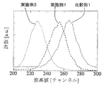
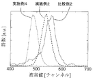
- This figure is a wave height distribution spectrum diagram when the thermal neutron of the scintillator for neutron detection of the present invention is irradiated.
- This figure is a wave height distribution spectrum diagram when the thermal neutron of the scintillator for neutron detection of the present invention is irradiated.
- This figure is a wave height distribution spectrum diagram when the thermal neutron of the scintillator for neutron detection of the present invention is irradiated.
- This figure is a wave height distribution spectrum diagram when the thermal neutron of the scintillator for neutron detection of the present invention is irradiated.
- This figure is a figure which shows the thickness dependence of the emitted light amount of the scintillator for neutron detection of this invention.
- the scintillator for neutron detection of the present invention is composed of a cordierite-type fluoride single crystal containing Eu, contains 0.0025 mol% or more and less than 0.05 mol% of Eu, and 0.80 atom / nm 3 or more of 6 Li. It consists of a cordierite-type fluoride single crystal.
- the basic structure of the cordierite-type fluoride single crystal is a single crystal of a compound represented by the chemical formula M X M Y M Z F 6
- M X always contains Li, and in addition to Li, Na, K, Rb, may include Cs, at least one or two or more elements selected from, M Y is, Ca, Mg, Ba, Sr , Cd, be at least one element selected from,
- M X always include Li necessary for detecting neutrons, preferably contains Na When performing charge adjustment.
- the single crystal is a hexagonal crystal belonging to the space group P31c, and can be easily identified by a powder X-ray diffraction technique.
- a corkyrite type crystal represented by the chemical formula of LiCaAlF 6 , LiSrAlF 6 , LiCa 1-x Sr x AlF 6 (0 ⁇ x ⁇ 1) is a large crystal. It is preferable because it is easy to produce and has a large light emission when used as a scintillator.
- LiCaAlF 6 is most preferable because it has a small effective atomic number, that is, low sensitivity to ⁇ rays.
- the effective atomic number is an index defined by the following formula.
- Effective atomic number ( ⁇ W i Z i 4 ) 1/4 (In the formula, Wi is the mass fraction of the i-th element among the elements constituting the scintillator, and Zi is the atomic number of the i-th element among the elements constituting the scintillator.)
- 6 Li content of Korukiraito type fluoride single crystal is 0.80atom / nm 3 or more.
- the sensitivity to neutron rays necessary for use as a neutron detection scintillator can be obtained.
- To further increase the sensitivity to neutron rays is preferably about 4atom / nm 3 or more the 6 Li content.
- the upper limit of 6 Li content is about 9 atoms / nm 3 .
- the 6 Li content that can be contained in the cordierite-type fluoride single crystal is theoretically about 9 atom / nm 3 at maximum, and a 6 Li content higher than this cannot be obtained.
- the 6 Li content means the number of 6 Li elements contained per 1 nm 3 of the scintillator.
- the incident neutron causes a nuclear reaction with the 6 Li to generate ⁇ rays. Therefore, the 6 Li content affects the sensitivity to neutron beams, and the sensitivity to neutron beams increases as the 6 Li content increases.
- Such 6 Li content select a chemical composition suitable scintillator for neutron detection, or can be appropriately adjusted by adjusting the content ratio of 6 Li of LiF or the like used as the Li raw material.
- the existence ratio of 6 Li, a presence ratio of 6 Li for all Li, presence in natural Li ratio is about 7.6%.
- a method for adjusting the abundance ratio of 6 Li a general-purpose raw material having 6 Li in a natural abundance ratio is used as a starting material, and the concentration is adjusted to the desired 6 Li abundance ratio, or 6 Li is preliminarily provided. There is a method in which a concentrated raw material concentrated to a 6 Li existing ratio or more is prepared, and the concentrated raw material and the general-purpose raw material are mixed and adjusted.
- the above 6 Li content can be determined by the following equation (1).
- the cordierite-type fluoride single crystal used in the present invention is a colorless or slightly colored transparent crystal, has good chemical stability, and deteriorates performance in a short period under normal use conditions. It is not allowed. Furthermore, mechanical strength and workability are also good, and it is easy to process and use it in a desired shape.
- the shape of the scintillator for detecting neutrons of the present invention needs to be thicker than 1 mm.
- the thickness in the present invention indicates the length in the direction perpendicular to the light receiving surface when the neutron detection scintillator is bonded to the light receiving surface of the photomultiplier tube.
- a typical shape is a rectangular parallelepiped or a cube whose shortest side has a length of more than 1 mm, or a disk or cylinder having a length perpendicular to the circle of more than 1 mm.
- the thickness is 1.5 mm or more, 2 mm or more, 4 mm or more, and 10 mm or more, the probability of the nuclear reaction of 6 Li contained in the neutron detection scintillator of the present invention and the neutron detection shown below can be improved. This is more preferable because the detection efficiency can be increased.
- the thickness is too thick, the efficiency of condensing the emitted light on the light receiving surface of the photomultiplier tube deteriorates as the surface area of the single crystal increases, so the upper limit of the thickness is preferably about 200 mm.
- the probability of causing a nuclear reaction is about 70% or more at a thickness of 1.5 mm or more, about 80% or more at a thickness of 2 mm or more, and about 80% or more at a thickness of 4 mm or more. 90% or more.
- about to 1eV of epithermal neutrons decrease neutron cross-sectional area of 6 Li is to about 1/5 or less
- the probability of nuclear reactions with 6 Li is the thickness 10mm or more to be about 70% or more.
- the cordierite-type fluoride single crystal used in the present invention contains an Eu element. By containing this element, light emission containing light in a wavelength region of about 370 nm that is easily received by a photomultiplier tube during neutron irradiation can be obtained. Controlling the content of Eu element contained in the cordierite-type fluoride single crystal, the neutron detection scintillator of the present invention having a thickness exceeding 1 to 10 mm for the purpose of obtaining high neutron detection efficiency as described above. It is extremely important when making.
- the content of Eu element needs to be 0.0025 mol% or more with respect to the single crystal compound as a basic structure in order to obtain light emission upon neutron irradiation. Furthermore, when it contains 0.01 mol% or more, since high light emission intensity is easy to be obtained at the time of neutron irradiation, it is more preferable. Moreover, it is necessary to suppress the content of Eu element to less than 0.05 mol%. When the content is 0.05 mol% or more, in the case of the scintillator for neutron detection of the present invention having a thickness exceeding 1 mm, the reduction in the amount of light emission during thermal neutron irradiation accompanying the increase in the single crystal thickness is significant. It is easy to cause harmful effects as a scintillator.
- Such an adverse effect is more preferable because the content of the Eu element can be more reliably prevented by suppressing the content of the Eu element to 0.04 mol% or less.
- the cordierite type fluoride single crystal used in the present invention may further contain at least one element selected from transition metals and rare earth elements.
- transition metals are Ti, V, Cr, Mn, Fe, Co, Ni, Cu, Zn, and rare earth elements are Ce, Pr, Nd, Er, Tm, Ho, Dy, Tb, Gd. , Sm, Yb, La, Lu, Y, Sc, and Pm are preferably used.
- transition metals are Ti, V, Cr, Mn, Fe, Co, Ni, Cu, Zn
- rare earth elements are Ce, Pr, Nd, Er, Tm, Ho, Dy, Tb, Gd. , Sm, Yb, La, Lu, Y, Sc, and Pm are preferably used.
- a cordierite fluoride single crystal in which light emission having a wavelength different from that of Eu-derived light emission is increased can be obtained.
- the content of these elements is preferably suppressed to be lower than the Eu content because it is difficult to quench the light
- C s kC 0 (1-g) k ⁇ 1 [2]
- C s is the Eu content [mol% (rare earth / Ca)] in the cordierite fluoride single crystal
- k is the effective segregation coefficient
- C 0 is the Eu content [mol% (rare earth / Ca )]
- G represents the solidification rate.
- the effective segregation coefficient is described in the literature (for example, Growth of Ce-doped LiCaAlF 6 and LiSrAlF 6 single crystals by the Czochralski technology CF 4 atmosphere). However, the effective segregation coefficient varies depending on the growth method.
- the effective segregation coefficient of Eu for LiCaAlF 6 is 0.025 in the case of the Czochralski method shown in Non-Patent Document 2, In the case of the micro pull-down method shown in Document 1, it was 0.05.
- the Eu content in the actual crystal can be examined by a general elemental analysis method (for example, ICP mass spectrometry, ICP emission analysis).
- a general elemental analysis method for example, ICP mass spectrometry, ICP emission analysis.
- the production method of the corklite-type fluoride single crystal used in the present invention is not particularly limited and can be produced by a known crystal production method, but is preferably produced by the Czochralski method.
- the Czochralski method it is possible to manufacture a cordierite-type fluoride single crystal containing Eu with excellent quality such as transparency, and it is possible to manufacture a large crystal with a diameter of several inches Become.
- a predetermined amount of raw material is filled in the crucible 1.
- a fluoride of the element is not particularly limited, but each is preferably 99.99% or more.
- the mixed raw material may be used in the form of powder or granules, or may be used after being sintered or melted and solidified in advance.
- M always the material of LiF contained in X F, it is preferable to use a material obtained by concentrating the Korukiraito type fluoride single crystal of 6 Li 6 Li in terms of ease and adjustment of the content.
- the abundance ratio of 6 Li in the Li element exceeds 7.6%. The higher the abundance ratio of 6 Li, the higher the neutron detection efficiency when using the grown crystal as a scintillator for neutron detection, which is preferable.
- the raw material powder of the crystalline compound serving as the basic structure can be weighed and mixed so as to have the same ratio as the ratio in the chemical formula of the compound to be produced.
- the measured value of EuF 3 contained in the cordierite-type fluoride single crystal used in the present invention be weighed more than the target content.
- the segregation coefficient used to calculate the content of the actual additive element from the weighed value varies depending on the growth conditions such as the type of additive element and the growth rate, so the actual concentration is examined by elemental analysis for each crystal production condition. It is desirable to decide. The same can be said when a transition metal and a rare earth element are contained.
- the raw material powder having high volatility at high temperature may be mixed in a large amount. Since the volatilization amount is completely different depending on the crystal growth conditions (temperature, atmosphere, and process), it is desirable to determine the weighing value by examining the volatilization amount in advance.
- the crucible 1, the heater 2, the heat insulating material 3, and the movable stage 4 filled with the raw materials are set as shown in FIG.
- another crucible with a hole at the bottom may be installed, and fixed to the heater 2 or the like, and hung with a double crucible structure.
- the seed crystal 5 is attached to the tip of the automatic diameter control device 6.
- a high melting point metal such as platinum may be used as the seed crystal.
- the crystallinity of the grown crystal is better when using a cordierite fluoride single crystal or a single crystal having a crystal structure close to it. It tends to be good.
- a LiCaAlF 6 single crystal having a rectangular parallelepiped shape having a size of about 6 ⁇ 6 ⁇ 30 mm 3 , cut, ground, and polished so that a side of 30 mm is along the c-axis direction can be used.
- the automatic diameter controller measures the total weight of the seed crystal and the grown crystal, adjusts the pulling speed of the seed crystal from the information, and controls the diameter of the crystal to be grown.
- a load cell for a pulling apparatus that is commercially available for crystal growth can be used.
- the inside of the chamber 7 is evacuated to 1.0 ⁇ 10 ⁇ 3 Pa or less using an evacuation apparatus, and then an inert gas such as high purity argon is introduced into the chamber to perform gas replacement.
- the pressure in the chamber after gas replacement is not particularly limited, but atmospheric pressure is common.
- a solid scavenger such as zinc fluoride or a gas scavenger such as tetrafluoromethane in order to avoid adverse effects due to moisture that cannot be removed even by the gas replacement operation.
- a method of mixing in the raw material in advance is preferable, and when using a gas scavenger, a method of mixing with the above inert gas and introducing it into the chamber is preferable.
- the raw material is heated and melted by the high frequency coil 8 and the heater 2.
- the heating method is not particularly limited, and for example, a resistance heating type carbon heater or the like can be appropriately used instead of the configuration of the high frequency coil and the heater.
- the melted raw material melt is brought into contact with the seed crystal.
- the crystal is pulled up while automatically adjusting the pulling speed under the control of the automatic diameter control device 6.
- the movable stage 4 may be appropriately moved in the vertical direction in order to adjust the liquid level. Containing Eu by continuously pulling up while adjusting the output of the high-frequency coil, separating from the liquid surface when it reaches the desired length, and cooling for a sufficient amount of time so that cracks do not occur in the grown crystal Corkylite-type fluoride single crystal can be obtained.
- the grown crystal may be annealed for the purpose of removing crystal defects caused by defects in fluorine atoms or thermal strain.
- the obtained corkyrite-type fluoride single crystal containing Eu is processed into a desired shape and used.
- a known cutting machine such as a blade saw or a wire saw, a grinding machine, or a polishing machine can be used without any limitation.
- the shape of the scintillator for detecting neutrons of the present invention is not particularly limited, but has a light emission surface facing a photomultiplier tube described later, and the thickness in the direction perpendicular to the light emission surface exceeds 1 mm. As described above, the thickness may be 2 to 10 mm or more depending on the purpose.
- the light emitting surface is preferably subjected to optical polishing. By having such a light exit surface, the light generated by the scintillator can be efficiently incident on the photomultiplier tube.
- the shape of the light emitting surface is not limited, and a shape according to the application such as a quadrangle with a side length of several mm to several hundred mm square or a circle with a diameter of several mm to several hundred mm is appropriately selected. Can be used.
- a light reflecting film made of aluminum, Teflon (registered trademark), or the like is provided on a surface that does not face the photomultiplier tube, so that the light dissipated by the scintillator can be prevented.
- the neutron detection scintillator of the present invention can be combined with a photomultiplier tube to form a neutron beam detector.
- the neutron detection scintillator of the present invention can be bonded to the light receiving surface of a photomultiplier tube with an optional optical grease or the like to form a neutron detector.
- the light-receiving surface of the photomultiplier tube to which the neutron detection scintillator is bonded may be covered with a light-shielding material made of any material that is difficult to transmit light in order to prevent light from entering the environment.
- the surface of the neutron detection scintillator other than the surface that is bonded to the light-receiving surface of the photomultiplier tube may be covered with a reflective material made of aluminum, Teflon (registered trademark), barium sulfate, etc. to increase the light collection efficiency.
- the whole may be covered with the above-described functions of the light shielding material and the reflective material.
- the photomultiplier tube can be used with high sensitivity by applying a voltage, and the detection of the neutron beam can be confirmed by observing the output electric signal.
- the electrical signal output from the photomultiplier tube may be input to an amplifier, a multi-wave height analyzer, etc., and measured by photon counting (photon counting method).
- the intensity of the neutron beam may be determined by inputting to an ammeter such as a picoammeter, evaluating current-voltage characteristics, and confirming a change in the amount of current.
- the scintillator for neutron detection of the present invention can be suitably used for measurement by photon counting.
- a position sensitive photomultiplier tube in which detectors having a sensitive area of several mm square are arranged in an array is used so as to cover a part or all of the photocathode.
- a neutron imaging apparatus By joining the scintillator of the invention, a neutron imaging apparatus can be obtained.
- a position sensitive photomultiplier tube that can detect scintillation light emitted from the crystal of the present invention is used.
- Optical grease or the like may be used for joining the light receiving surface and the crystal.
- the electrical signal output from the position sensitive photomultiplier tube can be read out using an arbitrary interface, and may be controlled by a personal computer using a control program.
- Examples 1 to 4 and Comparative Examples 1 to 8 Manufacture of neutron detection scintillators
- the manufacturing method of the scintillator for neutron detection which consists of a cordierite type
- the corklite type fluoride single crystal used in the present invention was produced.
- the basic structure of the single crystal was LiCaAlF 6.
- a high purity fluoride powder of LiF, CaF 2 , AlF 3 , EuF 3 having a purity of 99.99% or more was used.
- the LiF the abundance ratio of 6 Li is used as 95%.
- the crucible 1, the heater 2, and the heat insulating material 3 were made of high purity carbon.
- the crucible 1 filled with the mixed raw material was placed on the movable stage 4, and the heater 2 and the heat insulating material 3 were sequentially set around the crucible 1.
- a LiCaAlF 6 single crystal was cut, ground and polished so that a side of 30 mm along the c-axis direction with a 6 ⁇ 6 ⁇ 30 mm 3 rectangular parallelepiped shape was used as a seed crystal 5 and attached to the tip of an automatic diameter controller. .
- the inside of the chamber 6 is evacuated to 5.0 ⁇ 10 ⁇ 4 Pa by using an evacuation device comprising an oil rotary pump and an oil diffusion pump, and then a tetrafluoromethane-argon mixed gas is brought into the chamber 7 to atmospheric pressure. The gas was replaced.
- a high-frequency current was applied to the high-frequency coil 8, and the raw material was heated and melted by induction heating.
- the seed crystal 5 was moved and brought into contact with the liquid surface of the melted raw material melt. After adjusting the heater output so that the temperature at which the portion in contact with the seed crystal is solidified, the crystal was pulled up under the control of the automatic diameter controller 6 while automatically adjusting the pulling speed with a diameter of 55 mm as a target.
- the movable stage 4 is appropriately moved to adjust the liquid level to be constant, and continuously lifted while appropriately adjusting the output of the high frequency coil, and separated from the liquid level when the length becomes about 60 mm.
- a cordierite-type fluoride single crystal having a diameter of 55 mm and a length of about 60 mm and having a basic structure of LiCaAlF 6 was obtained.
- the obtained crystal was cut with a wire saw equipped with a diamond wire, ground and mirror-polished, and the length x width x thickness was 10 x 10 x 1 mm, 10 x 10 x 2 mm, 10 x 10 x 10 mm. It processed so that it might become a shape, and obtained the comparative example 1 and the scintillator examples 1 and 3 for neutron beam detection of this invention.
- the obtained scintillator for neutron beam detection is cut out from the part where the Eu content is about 0.0025 mol% (the part where the solidification rate g corresponding to the initial stage in single crystal growth is 1%) from the formula [2]. It was. Also, 6 Li content was 8.3atom / nm 3.
- the obtained scintillator for neutron detection measured the pulse height distribution spectrum during thermal neutron irradiation by the following method.
- FIG. 2 shows the configuration of the neutron beam detector of the present invention.
- the photomultiplier tube 9 R7600U manufactured by Hamamatsu Photonics Co., Ltd. having sensitivity to light of about 250 nm to 750 nm was used.
- the neutron detection scintillator of Example 1 was used as the neutron detection scintillator 10.
- the scintillator After the surface of the scintillator having a length of 10 mm and a width of 10 mm is bonded to the photocathode of the photomultiplier tube 9 with optical grease, the scintillator is shielded by a light shielding material 11 made of a black vinyl sheet so that light from the outside does not enter.
- Example 5 was adopted.
- the thermal neutron source a 252 Cf sealed radiation source placed in a polyethylene container was used.
- scintillation light emitted from the scintillator was measured by photon counting.
- the scintillation light was converted into an electric signal through the photomultiplier tube 9 to which a high voltage of 600 V was applied.
- the electric signal output from the photomultiplier tube 9 is a pulse-like signal reflecting the scintillation light
- the pulse height represents the emission intensity of the scintillation light
- the waveform thereof is obtained when the scintillation light is attenuated.
- the obtained wave height distribution spectra are shown in FIGS.
- the horizontal axis of the pulse height distribution spectrum represents the peak value of the electric signal, that is, the emission intensity of the scintillation light.
- the vertical axis represents the frequency of the electrical signal indicating each peak value.
- FIG. 3 shows Examples 1 and 3 and Comparative Example 1
- FIG. 4 shows Examples 2, 4 and Comparative Example 2
- FIG. 5 shows Comparative Examples 3, 5, and 7,
- FIG. 6 shows Comparative Examples 4 and 6 respectively.
- 8 is a wave height distribution spectrum by a neutron detection scintillator. 3 to 6 are drawn for each Eu content.
- the amount of light emitted (value on the horizontal axis) is read, the amount of light emitted when the thickness is 1 mm is normalized as 1, and the thickness dependence of the attenuation of the amount of light emitted is examined.
- the light emission amount is greatly reduced as the thickness increases with the Eu content of 0.05 and 0.1 mol%.
- the attenuation rate is about 10% or less less than the Eu content of 0.05 and 0.1 mol%. Recognize.
- the limit thickness that can secure the desired emitted light amount is reduced.
- the thickness of the scintillator is thicker (for example, when the thickness exceeds 10 mm)
- the comparative example in which the Eu content is 0.05 and 0.1 mol% has a greater thickness dependency of attenuation of light emission.
- the attenuation of the light emission amount becomes more prominent, and the embodiment in which the Eu content is 0.025 and 0.0025 mol% can favorably secure the desired light emission amount.
- the attenuation of the amount of light emission due to the thickness is not only easily detected by a photomultiplier tube, but also depends on where the nuclear reaction occurs in the neutron detection scintillator single crystal and the light emission intensity. As a result, differences in the received signal intensity increase, and it is necessary to set a wide peak value as the detection range, and it takes time to obtain the detection peak. Go down.
- the wave height distribution spectra of Examples 1 to 4 (FIGS. 3 and 4) having an Eu content of less than 0.05 mol% and the pulse height spectra of Comparative Examples 5 to 8 having an Eu content of 0.05 or more. Comparing (FIG. 5 and FIG.
- the entire peak is within a relatively narrow peak value (horizontal axis) range (within 100), whereas in the latter, the peak has a wide peak value (horizontal). It can be seen that the variation in the signal intensity of the former is small.
- the Eu content is 0.05 mol%.
- the detection peak in the wave height distribution spectrum of the neutron detector equipped with the scintillators of Comparative Examples 5 to 8 described above is significantly asymmetric.
- the pulse height distribution spectrum of the neutron detector equipped with the scintillators of Comparative Examples 6 and 7 it can be seen that the peaks are separated and have two peaks. Such peak separation is not a phenomenon seen in all scintillators.
- the scintillator performance has a difficult influence from the conventionally known technology. There is a possibility.
- the Eu content is 0.05, 0.1 mol% or more
- the detection peak becomes asymmetrical or the detection peak is separated into two.
- the Eu content is 0.025 and 0.0025 mol%, such a problem is not observed, and the example in which the Eu content is small is preferably used as a thick scintillator. be able to.
- the neutron detectors of Examples 5 to 8 are less attenuated in the amount of emitted light in the scintillator single crystal than the neutron detectors of Comparative Examples 9 to 16, and the signal when detecting the neutron beam It can be seen that the strength does not vary easily.
Abstract
Priority Applications (3)
| Application Number | Priority Date | Filing Date | Title |
|---|---|---|---|
| US14/001,181 US20130327946A1 (en) | 2011-02-24 | 2012-02-24 | Scintillator for Neutron Detection, and Neutron Radiation Detector |
| JP2013501144A JPWO2012115234A1 (ja) | 2011-02-24 | 2012-02-24 | 中性子検出用シンチレーター及び中性子線検出器 |
| EP12749292.4A EP2679652A4 (fr) | 2011-02-24 | 2012-02-24 | Scintillateur pour la détection des neutrons et détecteur de rayonnement de neutrons |
Applications Claiming Priority (2)
| Application Number | Priority Date | Filing Date | Title |
|---|---|---|---|
| JP2011038983 | 2011-02-24 | ||
| JP2011-038983 | 2011-02-24 |
Publications (1)
| Publication Number | Publication Date |
|---|---|
| WO2012115234A1 true WO2012115234A1 (fr) | 2012-08-30 |
Family
ID=46721006
Family Applications (1)
| Application Number | Title | Priority Date | Filing Date |
|---|---|---|---|
| PCT/JP2012/054594 WO2012115234A1 (fr) | 2011-02-24 | 2012-02-24 | Scintillateur pour la détection des neutrons et détecteur de rayonnement de neutrons |
Country Status (4)
| Country | Link |
|---|---|
| US (1) | US20130327946A1 (fr) |
| EP (1) | EP2679652A4 (fr) |
| JP (1) | JPWO2012115234A1 (fr) |
| WO (1) | WO2012115234A1 (fr) |
Cited By (2)
| Publication number | Priority date | Publication date | Assignee | Title |
|---|---|---|---|---|
| GB2499709A (en) * | 2012-01-26 | 2013-08-28 | Gen Electric | Lithium based scintillators for neutron detection |
| JP2018529830A (ja) * | 2015-08-06 | 2018-10-11 | ローレンス リバモア ナショナル セキュリティー, エルエルシー | K2PtCl6結晶構造を有するシンチレーター |
Families Citing this family (1)
| Publication number | Priority date | Publication date | Assignee | Title |
|---|---|---|---|---|
| JPWO2012121346A1 (ja) * | 2011-03-08 | 2014-07-17 | 株式会社トクヤマ | 中性子線検出装置 |
Citations (3)
| Publication number | Priority date | Publication date | Assignee | Title |
|---|---|---|---|---|
| WO2004086089A1 (fr) * | 2003-03-24 | 2004-10-07 | Hokushin Corporation | Materiau monocristal fluorure pour dosimetre thermoluminescent et dosimetre thermoluminescent associe |
| WO2009119378A1 (fr) * | 2008-03-24 | 2009-10-01 | 株式会社トクヤマ | Scintillateur pour la détection de neutrons et détecteur de neutrons |
| WO2011115179A1 (fr) * | 2010-03-19 | 2011-09-22 | 株式会社トクヤマ | Scintillateur pour la détection de neutrons, détecteur de neutrons et appareil d'imagerie neutronique |
Family Cites Families (2)
| Publication number | Priority date | Publication date | Assignee | Title |
|---|---|---|---|---|
| WO2012060382A1 (fr) * | 2010-11-02 | 2012-05-10 | 株式会社トクヤマ | Cristal de fluorure métallique et élément émettant de la lumière |
| JP5846960B2 (ja) * | 2012-02-24 | 2016-01-20 | 株式会社トクヤマ | 放射線検出器 |
-
2012
- 2012-02-24 EP EP12749292.4A patent/EP2679652A4/fr not_active Withdrawn
- 2012-02-24 JP JP2013501144A patent/JPWO2012115234A1/ja not_active Withdrawn
- 2012-02-24 US US14/001,181 patent/US20130327946A1/en not_active Abandoned
- 2012-02-24 WO PCT/JP2012/054594 patent/WO2012115234A1/fr active Application Filing
Patent Citations (3)
| Publication number | Priority date | Publication date | Assignee | Title |
|---|---|---|---|---|
| WO2004086089A1 (fr) * | 2003-03-24 | 2004-10-07 | Hokushin Corporation | Materiau monocristal fluorure pour dosimetre thermoluminescent et dosimetre thermoluminescent associe |
| WO2009119378A1 (fr) * | 2008-03-24 | 2009-10-01 | 株式会社トクヤマ | Scintillateur pour la détection de neutrons et détecteur de neutrons |
| WO2011115179A1 (fr) * | 2010-03-19 | 2011-09-22 | 株式会社トクヤマ | Scintillateur pour la détection de neutrons, détecteur de neutrons et appareil d'imagerie neutronique |
Cited By (3)
| Publication number | Priority date | Publication date | Assignee | Title |
|---|---|---|---|---|
| GB2499709A (en) * | 2012-01-26 | 2013-08-28 | Gen Electric | Lithium based scintillators for neutron detection |
| GB2499709B (en) * | 2012-01-26 | 2014-11-19 | Gen Electric | Lithium based scintillators for neutron detection |
| JP2018529830A (ja) * | 2015-08-06 | 2018-10-11 | ローレンス リバモア ナショナル セキュリティー, エルエルシー | K2PtCl6結晶構造を有するシンチレーター |
Also Published As
| Publication number | Publication date |
|---|---|
| US20130327946A1 (en) | 2013-12-12 |
| JPWO2012115234A1 (ja) | 2014-07-07 |
| EP2679652A1 (fr) | 2014-01-01 |
| EP2679652A4 (fr) | 2014-09-10 |
Similar Documents
| Publication | Publication Date | Title |
|---|---|---|
| RU2494416C2 (ru) | Сцинтиллятор для детектирования нейтронов и нейтронный детектор | |
| WO2012121346A1 (fr) | Dispositif de détection à faisceau de neutrons | |
| RU2596765C2 (ru) | Сцинтиллятор, радиационный детектор и способ обнаружения излучения | |
| JP5877417B2 (ja) | 中性子検出用シンチレーター及び中性子線検出器 | |
| WO2011115179A1 (fr) | Scintillateur pour la détection de neutrons, détecteur de neutrons et appareil d'imagerie neutronique | |
| JP5575123B2 (ja) | シンチレーター | |
| WO2012115234A1 (fr) | Scintillateur pour la détection des neutrons et détecteur de rayonnement de neutrons | |
| JP5868329B2 (ja) | 中性子シンチレーター | |
| JP5634285B2 (ja) | コルキライト型結晶、中性子検出用シンチレーター及び中性子線検出器 | |
| JP5737974B2 (ja) | 中性子検出用シンチレーター及び中性子線検出器 | |
| JP5737978B2 (ja) | 中性子検出用シンチレーター及び中性子線検出器 | |
| JP5905956B2 (ja) | 金属フッ化物結晶、発光素子、シンチレーター、中性子の検出方法及び金属フッ化物結晶の製造方法 | |
| JP5652903B2 (ja) | 中性子シンチレータ用酸化物結晶及び中性子検出器 | |
| JP5842292B2 (ja) | 中性子シンチレータ用酸化物結晶及びこれを用いた中性子シンチレータ | |
| WO2012026584A1 (fr) | Scintillateur de détection de neutrons et détecteur de rayonnement neutronique |
Legal Events
| Date | Code | Title | Description |
|---|---|---|---|
| 121 | Ep: the epo has been informed by wipo that ep was designated in this application |
Ref document number: 12749292 Country of ref document: EP Kind code of ref document: A1 |
|
| ENP | Entry into the national phase |
Ref document number: 2013501144 Country of ref document: JP Kind code of ref document: A |
|
| WWE | Wipo information: entry into national phase |
Ref document number: 14001181 Country of ref document: US |
|
| NENP | Non-entry into the national phase |
Ref country code: DE |
|
| WWE | Wipo information: entry into national phase |
Ref document number: 2012749292 Country of ref document: EP |