WO2012115090A1 - 炊飯器 - Google Patents
炊飯器 Download PDFInfo
- Publication number
- WO2012115090A1 WO2012115090A1 PCT/JP2012/054095 JP2012054095W WO2012115090A1 WO 2012115090 A1 WO2012115090 A1 WO 2012115090A1 JP 2012054095 W JP2012054095 W JP 2012054095W WO 2012115090 A1 WO2012115090 A1 WO 2012115090A1
- Authority
- WO
- WIPO (PCT)
- Prior art keywords
- rice
- stirring
- rice cooker
- unit
- polished
- Prior art date
- Legal status (The legal status is an assumption and is not a legal conclusion. Google has not performed a legal analysis and makes no representation as to the accuracy of the status listed.)
- Ceased
Links
Images




Classifications
-
- A—HUMAN NECESSITIES
- A47—FURNITURE; DOMESTIC ARTICLES OR APPLIANCES; COFFEE MILLS; SPICE MILLS; SUCTION CLEANERS IN GENERAL
- A47J—KITCHEN EQUIPMENT; COFFEE MILLS; SPICE MILLS; APPARATUS FOR MAKING BEVERAGES
- A47J27/00—Cooking-vessels
- A47J27/004—Cooking-vessels with integral electrical heating means
-
- A—HUMAN NECESSITIES
- A23—FOODS OR FOODSTUFFS; TREATMENT THEREOF, NOT COVERED BY OTHER CLASSES
- A23L—FOODS, FOODSTUFFS OR NON-ALCOHOLIC BEVERAGES, NOT OTHERWISE PROVIDED FOR; PREPARATION OR TREATMENT THEREOF
- A23L7/00—Cereal-derived products; Malt products; Preparation or treatment thereof
- A23L7/10—Cereal-derived products
- A23L7/196—Products in which the original granular shape is maintained, e.g. parboiled rice
Definitions
- the present invention relates to a rice cooker.
- washing polished rice before cooking rice is widely recognized as common sense, but since washing rice before cooking is cumbersome, techniques for automating this have been developed.
- Patent Literature 1 Japanese Utility Model Publication No. 62-182132
- a stirring blade driven by an electric motor is attached to a lid body that is attached to the inner pot of a rice cooker, and the stirring blade is rotated to rotate the rice. Is washing.
- Patent Document 2 Japanese Patent Laid-Open No. 2-21312 describes a method for washing rice by rotating the rice cooker itself.
- Patent Document 3 Japanese Patent Laid-Open No. 2009-2014439
- Patent Document 4 Japanese Patent Laid-Open No. 2000-139374
- the texture is improved by adding a collagen peptide to non-washed rice deteriorated by long-term storage during cooking.
- Patent Documents 1 and 2 Such a decrease in the taste of cooked rice is not described at all in Patent Documents 1 and 2 above. Moreover, the method for improving the taste of the cooked rice is not described at all in Patent Documents 1 and 2.
- Patent Document 4 the effect of reforming old rice can be obtained only when electrolytically generated water can be prepared. Therefore, it is difficult to widely spread rice cookers that exhibit the above-described reforming effects in general households.
- the surface of polished rice endosperm is covered with a paste layer (outside) and a sub-paste layer (inside).
- the paste powder layer and the sub-paste powder layer are collectively referred to as cocoons, and it is known that the candy is packed with nutrition and umami.
- milled rice begins to oxidize gradually from the paste layer immediately after milling, so that the surface of milled rice is covered with an oxidized layer, so-called deteriorated rice, and the taste of cooked rice is therefore lowered. It has been.
- the present inventor removes the oxidized portion causing the low taste by shaving the surface of the polished rice even in degraded rice, and the taste and nutrition (for example, part of the paste layer and sub paste powder)
- the taste and nutrition for example, part of the paste layer and sub paste powder
- the portion of the glue layer of the cocoon becomes difficult to scrape over time after harvesting, and if the operation is performed to uniformly scrape the paste layer under the same conditions, for example, in the case of new rice, the glue layer is shaved too much. In the case of degraded rice after one year from harvesting, there was a problem that the glue layer was not sharpened.
- an object of the present invention is to propose a rice cooker that can realize a cooked rice with good taste and leave a suitable amount of rice bran in the polished rice even if the polished rice is degraded rice. .
- the rice cooker of the present invention is A rice cooker, An agitation part for agitating the polished rice put together with water in the rice cooker; A heating unit for heating the rice cooker; A sequence control unit for controlling the stirring unit and the heating unit, The sequence control unit A deterioration level estimation process for estimating the degree of deterioration of the polished rice, Based on the degree of deterioration of the polished rice estimated in the deterioration level estimation step, an agitation time derivation step for deriving an agitation time suitable for the degree of deterioration, A first stirring step of stirring the polished rice in the stirring unit with the stirring time; After the water in the rice cooker has been purified by replacing the water in the rice cooker or using an adsorbent, the soaked polished rice in the water in the rice cooker is immersed in the water in the rice cooker. The steps are sequentially performed before the heating step of heating the rice cooker with the heating unit is started.
- the stirring time suitable for the degree of deterioration is derived based on the degree of deterioration of the polished rice estimated in the deterioration level estimating step.
- the polished rice is stirred in the stirring portion for the stirring time derived in the stirring time deriving step.
- the said polished rice mutually rubs against each other, and the wrinkles on the surface of polished rice can be shaved.
- the stirring time is a time suitable for the degree of degradation of the polished rice, even if the polished rice is deteriorated rice, an appropriate amount of koji can be left on the polished rice, and as a result, the nutrition and taste of koji remain. You can cook cooked rice. That is, cooked rice with good taste can be realized.
- the polished rice is stirred longer than the stirring time in the first stirring step, the milled rice will be excessively shaved. On the other hand, if the polished rice is stirred longer than the stirring time, There is a high possibility that the shaving will be insufficient.
- the sequence control unit After the water in the rice cooker has been purified by replacing the water in the rice cooker or by using an adsorbent, and before the soaking step, the polished rice is used for the preset time. A second stirring step of stirring in the stirring unit is performed.
- the milled rice left in the first stirring step can be shaved by stirring the polished rice in the rice cooker with the stirring unit.
- water absorption of the polished rice can be promoted in the soaking step after the second stirring step.
- the rice cooker can be cooked by heating the rice cooker with the heating unit to leave the nutrition and taste of rice cake.
- a rice milling date input unit is provided for the user to input the milling date of the milled rice to be put in the rice cooker.
- the degree of deterioration of the polished rice in the rice cooker is estimated based on the rice polishing date input by the rice polishing date input unit.
- the user since the date of rice polishing is usually entered in the rice bag, the user inputs the rice polishing date of the polished rice to be put in the rice cooker at the rice polishing date input unit. Can do.
- the degree of degradation of the polished rice in the rice cooker is estimated based on the date of rice milling entered in the rice milling date input unit, so that the accuracy of this estimation can be increased. it can.
- the rice milling date is input by the user, it is not necessary to mount a sensor for detecting the rice milling date, and an increase in manufacturing cost can be suppressed.
- the degradation level estimation step the degree of degradation of the polished rice in the rice cooker is estimated based on the options selected by the selection unit.
- the user can select one of a plurality of options with the selection unit.
- Each of these options is for obtaining the number of days that have elapsed since the date of harvesting the straw.
- the grade of degradation of the polished rice in a rice cooker is estimated based on the choice selected by the said selection part, the precision of this estimation can be improved.
- the sequence control unit determines the degree of deterioration based on the deterioration level estimation process for estimating the degree of deterioration of the polished rice and the degree of deterioration of the polished rice estimated in the deterioration level estimation process.
- the stirring time deriving step for deriving the combined stirring time, the stirring time, the first stirring step for stirring the polished rice in the stirring unit, and replacing the water in the rice cooker, or by using an adsorbent, After the water in the inside is purified, a preset time, the second stirring step of stirring the water in the rice cooker and the polished rice in the stirring unit, and soaking in the water in the rice cooker for a preset time, The soaking process of absorbing the water in the rice cooker into the polished rice is sequentially performed before starting the heating process of heating the rice cooking pot in the heating unit, so even if the polished rice is deteriorated rice, an appropriate amount for the polished rice Leave rice cake and realize cooked rice with good taste .
- FIG. 1 is a schematic cross-sectional view of a rice cooker according to an embodiment of the present invention.
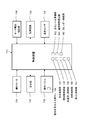
- FIG. 2 is a control block diagram of the rice cooker.
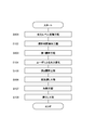
- FIG. 3 is a flowchart for explaining rice cooking by the rice cooker.
- FIG. 4 is a diagram showing the relationship between the steps for cooking rice and the temperature in the inner pot.
- FIG. 5 is a flowchart for explaining the deterioration level estimation step and the stirring time derivation step of the embodiment.
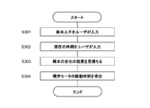
- FIG. 6 is a flowchart for explaining a deterioration level estimating step and a stirring time deriving step according to a modification of the present invention.
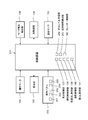
- FIG. 7 is a control block diagram of a rice cooker according to a modification of the present invention.
- FIG. 1 is a schematic cross-sectional view of a rice cooker according to an embodiment of the present invention.
- FIG. 2 is a control block diagram of the rice cooker.
- FIG. 3 is a flowchart for explaining rice cooking by the rice cooker.
- FIG. 8 is a graph for explaining the difference in the remaining amount of milled rice having different months since harvest.
- FIG. 9 is a graph for explaining the difference in the remaining amount of milled rice having a different number of days since the milling date.
- FIG. 10 is a schematic cross-sectional view of a rice cooker according to a modification of the present invention.
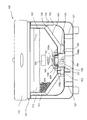
- FIG. 1 schematically shows a cross section of a rice cooker 100 according to an embodiment of the present invention cut along a vertical plane.
- the rice cooker 100 is attached to the rice cooker body 101, the inner pot 102 accommodated in the rice cooker body 101, and the upper portion of the rice cooker body 101 so as to be freely opened and closed, and can be closed to cover the inner pot 102.
- a lid 112 a heating unit 103 for heating the inner pot 102 accommodated in the rice cooker body 101, an agitation motor 104 disposed outside the inner pot 102, and a rotatable arrangement within the inner pot 102, the inner pot 102 And a stirring blade 105 that stirs the milled rice 111 and tap water 113 therein.
- the inner pot 102 is an example of the rice cooker of the present invention
- the stirring blade 105 is an example of the stirring section of the present invention
- the tap water 113 is an example of the water of the present invention.
- the rice cooker body 101 has an outer case 119 and an inner case 120.
- the inner case 120 is made of a material having heat resistance and electrical insulation.
- the inner case 120 is supported by the outer case 119 via a heat insulating member 121.
- a temperature sensor 110 is attached to the inner case 120.
- the temperature sensor 110 has a detection unit 110a that passes through the heating unit 103 and contacts the bottom of the inner pot 102, and detects the temperature of the inner pot 102 by the detection unit 110a. Further, the temperature of the tap water 113 in the inner pot 102 can be indirectly detected based on the temperature of the inner pot 102 detected by the temperature sensor 110.
- the inner pot 102 is formed of, for example, a high heat conductive member such as aluminum and has an inner surface coated with a fluororesin for preventing adhesion of an object to be heated.
- the stirring motor 104 is disposed on the bottom of the outer case 119.
- a rotor 106 is attached to the rotating shaft 104 a of the stirring motor 104.
- the rotating shaft 104 a and the rotor 106 are covered with a cover 122.
- the stirring motor 104 and the rotor 106 are examples of the stirring unit of the present invention.
- a plurality of rotor-side magnets 107 that are a plurality of drive-side magnets are arranged at equal intervals in the circumferential direction on the outer periphery of the rotor 106. Further, the rotor 106 is disposed so as to separate a predetermined gap below a cylindrical convex portion 102a that protrudes inward at the bottom of the inner hook 102.
- the rotor-side magnet 107 is an example of the stirring unit of the present invention.
- the stirring blade 105 is rotatably fitted to the convex portion 102 a of the inner hook 102, and the convex portion 102 a serves as a support base for the stirring blade 105.
- the surface of the stirring blade 105 opposite to the convex portion 102a side, that is, the surface in contact with the milled rice 111 in the stirring blade 105 is an uneven surface.
- the stirring blade 105 includes an annular yoke 109 and a plurality of stirring blade-side magnets 108 which are arranged at equal intervals in the circumferential direction inside the yoke 109 and are a plurality of driven-side magnets.
- the stirring blade 105 has a magnet 114 at the center upper portion, and this magnet 114 plays a role of attracting the rotor side magnet 107 and holding the stirring blade 105 on the convex portion 102 a of the inner hook 102.
- the stirring blade side magnet 108 is disposed so as to overlap the rotor side magnet 107 in the radial direction, and is magnetically coupled to the rotor side magnet 107.
- the stirring blade side magnet 108 magnetically coupled to the rotor side magnet 107 also rotates, and as a result, the stirring blade 105 rotates. .
- the heating unit 103 is attached to the inner case 120 via attachment members 123 and 124 that are insulators and heat insulators, and is supported by the inner case 120 via the attachment members 123 and 124.
- the heating unit 103 has at least one of a resistance heater and an induction coil.
- a magnetic material such as stainless steel that improves the heating efficiency is attached to the outer surface of the inner pot 102.
- FIG. 2 is a control block diagram of the rice cooker 100.
- the rice cooker 100 includes a control device 131 including a microcomputer, an input / output circuit, a timer, a memory, and the like.
- This control device 131 is based on an operation signal from the operation panel 132, a detection signal from the temperature sensor 110, a detection signal from the motor current detection unit 136, and the like, and a heating circuit for the display unit 133, the stirring motor 104, and the heating unit 103. 135 and the like are controlled.
- the operation panel 132 and the display unit 133 are provided on the front side of the rice cooker body 101.
- the liquid crystal display of the display unit 133 displays a cooking menu, cooking status, and the like.
- the control device 131 is disposed in a space between the outer case 119 and the inner case 120.
- a power supply unit (not shown) is also disposed in the space, and the power supply unit includes a heating circuit 135.
- the control device 131 is an example of the sequence control unit of the present invention.
- the control device 131 matches the degree of deterioration based on the deterioration level estimating unit 142 that estimates the degree of deterioration of the polished rice 111 and the degree of deterioration of the polished rice 111 estimated by the deterioration level estimating unit 142.
- the milled rice 111 immersed in the tap water 113 in the inner pot 102 is stirred with the stirring blade 105 to cut the surface of the milled rice 111, and the surface of the surface of the milled rice 111 is controlled by the paddy cutting control unit 138.
- the heating unit 10 with the low temperature soaking control unit 139 soaking the milled rice 111 in which tap rice has been cut in the tap water 113 and the rice cake cut by the rice bran cutting control unit 138 remains in the inner pot 102.
- a control unit 141 steamed cook by steam the cooked rice obtained by the heating control section 140, and a recognizing calendar function unit 145 of the current date.
- the deterioration level estimating unit 142, the stirring time deriving unit 143, the rice washing control unit 137, the rice bran cutting control unit 138, the low temperature dipping control unit 139, the heating control unit 140, and the steaming control unit 141 are configured by software. Further, stirring of the polished rice 111 by the rice washing operation unit 137 and the koji cutting control unit 138 is performed before the heating control unit 140 heats the inner pot 102.
- the operation panel 132 is provided with a rice milling date input button 144 for the user to input the milling date of the milled rice.
- the rice milling date input button 144 is an example of a rice milling date input unit.
- the user puts a desired amount of polished rice 111 and tap water 113 for washing rice into the inner pot 102, stores the inner pot 102 in the rice cooker body 101, and then inputs a rice milling date input button on the operation panel 132. 144, the milling date of milled rice 111 in the inner pot 102 is input.
- the deterioration level estimation unit 142 of the control device 131 sets the milled rice 111 in the inner pot 102 based on the rice milling date input by the user. The degree of deterioration is estimated (step S101).
- the degree of degradation of the polished rice 111 is proportional to the amount of the portion oxidized in the koji and the amount of the portion denatured in the koji. For example, when the amount of the oxidized or denatured portion of the polished rice 111 is increased, the degree of deterioration of the polished rice 111 is high. That is, the high degree of degradation of the polished rice 111 means that the degradation of the polished rice 111 is progressing.
- the stirring time deriving unit 143 of the control device 131 derives the stirring time that matches the degree of deterioration estimated by the deterioration level estimating unit 142 (step S102).
- the rice washing operation unit 137 of the control device 131 stirs the polished rice 111 in the inner pot 102 with the stirring blade 105 (step S103).
- the first stirring step in step S103 is an alternative to conventional rice washing by hand, and is rice washing for leaving moderately wrinkles on the surface of polished rice 111.
- the stirring blade 105 continuously rotates at, for example, 400 rpm for the stirring time derived by the stirring time deriving unit 143. Further, the heating unit 103 is not turned on during the first stirring step.
- control by the control apparatus 131 stops until the 2nd stirring process of below-mentioned step S105 starts.
- the user once takes out the inner pot 102 from the rice cooker main body 101, throws away the tap water 113 for washing the rice used in the first stirring step, and newly pours the tap water 113 for cooking rice into the inner pot 102.
- the inner pot 102 is again stored in the rice cooker body 101 (step S104).
- Step S105 when the user selects “rice cooking mode” by operating the operation panel 132, the rice bran cutting control unit 138 of the control device 131 stirs the polished rice 111 in the inner pot 102 with the stirring blade 105 for a preset time.
- the second stirring process in step S105 is performed such that a part of the rice cake left on the surface of the polished rice 111 in the first stirring process is cut.
- the stirring blade 105 continuously rotates, for example, at 400 rpm, for example, for 5 minutes. Further, the heating unit 103 is not turned on during the second stirring step.
- the low-temperature dipping control unit 139 of the control device 131 keeps the heating unit 103 in the OFF state, and uses the polished rice 111, the surface of which has been cut off in the first and second stirring steps, to cook rice. For example, it is immersed in water 113 for 12.5 minutes (step S106). Note that the low-temperature dipping process in step S106 is an example of the dipping process of the present invention.
- the polished rice 111 is cooked and steamed by the ON / OFF control of the heating unit 103 by the heating control unit 140 and the steaming control unit 141 of the control device 131 (steps S107 and S108).
- the stirring blade 105 is intermittently rotated. The stirring blade 105 is not rotated.
- the first stirring step replaces the operation of the user sharpening the polished rice 111 by hand. Therefore, the user can omit the work of sharpening the polished rice 111 by hand. In addition, there is an advantage that the user does not have to put his hand into the water, especially in winter when the water is cold or when the nail is subjected to nail art.
- the polished rice 111 rubs against each other, and the surface of the polished rice 111 is shaved.
- the polished rice 111 is stirred for the stirring time derived by the stirring time deriving unit 143. Therefore, even if the polished rice 111 is deteriorated rice, it is oxidized in the surface of the polished rice 111.
- the denatured portion can be shaved to leave an appropriate amount of straw on the surface of the polished rice 111.
- the rice cake shaved from the surface of the polished rice 111 in the second stirring step remains in the inner pot 102, and the rice is cooked in this state, so that the nutrition and taste of rice cake can be left in the cooked rice.
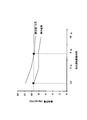
- FIG. 4 is a diagram showing the relationship between each step after the first stirring step and the temperature in the inner pot. 4 corresponds to the temperature of the tap water 113 in the inner pot 102. 4 shows the ON / OFF timing of the stirring motor 104.
- the heating unit 103 is kept in an OFF state, and the inner pot temperature is the same as the room temperature.
- the first stirring step is automatically performed in response to the user selecting “rice washing mode” by operating the operation panel 132 (automatic rice washing mode).
- the user changes the water in the inner pot 102.
- the heating unit 103 is held in an OFF state even during the water change.
- the operation is automatically performed sequentially in response to the user selecting “rice cooking mode” by operating the operation panel 132 (automatic rice cooking mode). More specifically, during the second stirring step, the heating unit 103 is maintained in an OFF state, and the inner pot temperature is the same as the room temperature. When the second stirring step is completed, the stirring motor 104 is turned off, and the low temperature soaking step is performed for 12.5 minutes. And the heating process which heats the inner pot 102 by the heating part 103 is started after the said low temperature immersion process. During the preset time after the start of this heating step, the stirring motor 104 is intermittently turned on to help equalize the temperature of the tap water 113 in the inner pot 102. In addition, when the said heating process starts and the temperature in an inner pot reaches 60 degreeC, after hold
- FIG. 5 is a flowchart for explaining the deterioration level estimating step and the stirring time deriving step in more detail.
- the user inputs the milling date of milled rice 111 using the milling date input button 144 on the operation panel 132 (step S201).
- the deterioration level estimation unit 142 counts the number of days that have elapsed from the rice milling date input by the user to the current date (step S202).
- the current date is the current date recognized by the calendar function unit 145 and the date when the rice milling date input button 144 is operated.
- the deterioration level estimation unit 142 estimates the degree of deterioration of the milled rice 111 in the inner pot 102 (oxidation amount and modification amount of rice bran) based on the number of days (step S203). For example, if the number of days elapsed from the date of rice polishing to the current date is within 7 days, the degree of degradation of the polished rice 111 is estimated to be “low”, while the number of days elapsed from the date of rice polishing to the current date is 1 If it is more than a month, the degree of deterioration of the polished rice 111 is estimated as “high”.
- the stirring time deriving unit 143 derives the driving time of the stirring motor 104 corresponding to the degree of deterioration estimated by the deterioration level estimating unit 142 (step S204).
- This drive time is relatively short when the degree of degradation of the polished rice 111 is estimated to be “low”, while compared to the degree of degradation of the polished rice 111 that is estimated to be “high”. It will be a long time.
- a table indicating the relationship between the degree of deterioration of the polished rice 111 and the drive time of the stirring motor 104 may be stored in the memory of the control device 131 in advance.
- FIG. 6 is a flowchart for explaining a modification of the deterioration level estimation step and the stirring time derivation step.
- step S301 when the user obtains a new rice as the polished rice 111 to be put in the inner pot 102, “new rice acquisition” is input on the operation panel 132 (step S301). Thereby, the control apparatus 131 memorize
- the user selects “current time” from the operation panel 32 (step S302).
- the “current time” includes “January to March”, “April to June”, “July to September”, and “October to December”. For example, if January is selected, select “January to March”, if May, “April to June”, select September to "July to September”, select November to "October to December” Will do.
- the degree of deterioration of the milled rice 111 in the inner pot 102 (the amount of oxidation and the amount of modification) is estimated based on the number of days (step S303). For example, if the “current time” selected in step S303 is “October to December”, the year in which this “current time” is selected is the same as the year in which “new rice acquisition” is input in step S301. If so, the degree of degradation of the polished rice 111 is estimated to be “low”. In that case, if the year in which the “current time” is selected is the year after the year in which “new rice acquisition” is input in step S301, the degree of degradation of the polished rice 111 is estimated to be “high”.
- step S304 the drive time of the stirring motor 104 corresponding to the degree of deterioration estimated in step S303 is derived (step S304).
- This drive time is relatively short when the degree of degradation of the polished rice 111 is estimated to be “low”, while compared to the degree of degradation of the polished rice 111 that is estimated to be “high”. It will be a long time.
- a table indicating the relationship between the degree of degradation of the polished rice 111 and the driving time of the stirring motor 104 may be stored in advance in a memory of the control device 231 described later. Further, the memory may store data indicating the relationship between the new rice and the harvest date of the straw.
- FIG. 7 is a control block diagram of the rice cooker provided with the control device 231 for performing each step of the flowchart of FIG.
- the same components as those shown in FIG. 2 are designated by the same reference numerals as those of the components in FIG.
- the control device 231 is different from the control device 131 in FIG. 2 in that the control device 231 includes a deterioration level estimation unit 242 that performs step S303 and an agitation time deriving unit 243 that performs step S304.
- the control device 231 is an example of the sequence control unit of the present invention.
- the operation panel 232 that sends an operation signal to the control device 231 has a new rice acquisition input button 201 for inputting “new rice acquisition” in step S301, and “January to March” in step S302.
- the first selection button 202, the second selection button 203, the third selection button 204, and the fourth selection button 205 are examples of the selection unit of the present invention.
- FIG. 8 is a graph for explaining the difference in the remaining amount of milled rice having different months since harvest. Note that the rice washing operation driving time in FIG. 8 corresponds to the time during which the stirring motor 104 is driven.
- the condition that the polished rice immediately after harvesting (for example, less than one month after harvesting), the polished rice that has passed 6 months since harvesting, and the polished rice that has passed 12 months after harvesting were stirred by the rice cooker 100. Then, the residual amount of rice bran after each stirring was determined.
- This residual amount of soot is determined by measuring magnesium, which is a mineral contained in a large amount in the soot.
- magnesium is quantified by an induction plasma emission analysis method (Kensha-sha new food analysis handbook P162).
- the remaining amount of rice bran when the rice washing operation is performed for 1 minute on the polished rice immediately after harvesting is set as an appropriate amount of remaining rice cake. If it does so, about the polished rice which several months passed after harvesting, the washing
- FIG. 9 is a graph for explaining the difference in the residual amount of milled rice with different days elapsed from the date of milling. Note that the rice washing operation driving time in FIG. 9 corresponds to the time during which the stirring motor 104 is driven.
- the amount of white rice bran was determined. As a result, it was found that, when the washing operation driving time is the same, the remaining amount of rice bran is higher in polished rice that has been polished for days than in polished rice that has not passed in days.
- the remaining amount of rice bran when the rice washing operation is performed on the polished rice immediately after the rice polishing for 1 minute is set as an appropriate amount of remaining rice cake. Then, as shown by the asterisk in FIG. 9, it is appropriate to perform the polishing for 5 minutes for the polished rice that has passed the number of days corresponding to one month from the time of polishing.
- the user changes the water in the inner pot 102 between the first stirring process and the second stirring process, but the user does not change the water in the inner pot 102 between the first stirring process and the second stirring process. It is possible not to change the water.
- the adsorbent activated carbon, adsorbent filter or adsorbent ceramic material
- the soot separated from the rice 111 is adsorbed. Can be adsorbed on the material. Therefore, even if the user does not change the water in the inner pot 102, the cleanliness of the tap water 113 in the inner pot 102 can be increased.
- the adsorbent 150 may be taken out from the inner pot 102 after the first stirring step and before the second stirring step is started or may not be taken out.
- both the first stirring step and the second stirring step are performed, but only the first stirring step may be performed.
- Heating circuit 136 Motor current detection unit 137 ... Rice washing control unit 138 ... Powder cutting control unit 139 ... Low temperature dipping control unit 140 ... Heating control unit 141 ... Steaming control unit 142,242 ... Deterioration level estimation Part 143,243 ... Agitation time deriving part 144 ... Rice date input button 45 ... calendar function unit 150 ... adsorbent 201 ... Beginner obtain input buttons 202 ... ... first selection button 203: second selection button 204 ... third selection button 205 fourth selection button
Landscapes
- Engineering & Computer Science (AREA)
- Food Science & Technology (AREA)
- Health & Medical Sciences (AREA)
- Nutrition Science (AREA)
- Life Sciences & Earth Sciences (AREA)
- Chemical & Material Sciences (AREA)
- Polymers & Plastics (AREA)
- Cookers (AREA)
- Cereal-Derived Products (AREA)
Abstract
炊飯器は、炊飯釜内に水と共に入れられた精白米を攪拌する攪拌翼,撹拌モータ(104)と、内釜を加熱する加熱部と、加熱部および攪拌モータ(104)を制御する制御装置(131)とを備える。制御装置(131)は、精白米の劣化の程度を見積もる劣化レベル見積工程と、劣化レベル見積工程で見積もった精白米の劣化の程度に基づいて、この劣化の程度に合った攪拌時間を導出する攪拌時間導出工程と、攪拌時間、精白米を攪拌部で攪拌する第1攪拌工程と、炊飯釜内の水を入れ替えること、または、吸着材を用いることにより、炊飯釜内の水が浄化された後、第1攪拌工程を経た精白米を炊飯釜内の水に浸す浸し工程とを、炊飯釜を加熱部で加熱する加熱工程を開始する前に順次行う。
Description
本発明は炊飯器に関する。
炊飯前に精白米を洗うことは常識として広く一般に認識されているが、炊飯前の米を洗う作業は面倒であるので、これを自動化するための技術が開発されている。
特許文献1(実開昭62-182132号公報)に開示された技術では、炊飯器の内釜に冠着する蓋体に電動機で駆動される攪拌羽根を取り付け、攪拌羽根を回転させることによって米を洗っている。
また、特許文献2(特開平2-213312号公報)には、炊飯釜自体を回転させて洗米を行う方法が記載されている。
一方、従来、美味しい炊飯米を得るために様々な炊飯器が市販されているが、精米後の各家庭での米の保存状態によって同じ炊飯器を使用しても炊き上がりが異なってしまう。すなわち、精米直後の米は美味しく炊けるが、精米後室温で保存した米は、精白米表面の脂質層が徐々に酸化するため、炊飯時に吸水不足となり、美味しく炊けないことが度々あった。特に、梅雨から夏にかけては室温の上昇と共に脂質層の酸化スピードは速まり、新米が出てくる直前の8月から9月の米から美味しい炊飯米を得ることはできなかった。
上記炊飯米の美味しさを改善する技術としては、特許文献3(特開2009-201439号公報)や特許文献4(特開2000-139374号公報)に開示されている。
上記特許文献3では、炊飯の際、長期保存で劣化した無洗米にコラーゲンペプチドを添加することで食感の改善を行っている。
上記特許文献4では、米を洗う洗米工程と、この洗米工程を経て水切りされた米を浸漬する浸漬工程と、この浸漬工程を経て水切りされた米を加水する加水工程との全てにおいて、有隔膜電解にて生成された電解生成水(酸性水およびアルカリ性水)を使用することで、古米の改質効果を得ている。
このような炊飯米の食味の低下は、上記特許文献1,2において全く記載されていない。また、上記炊飯米の食味を改善する方法も、上記特許文献1,2において全く記載されていない。
また、上記特許文献3のように、コラーゲンペプチドを劣化米に添加することによって、劣化米による炊飯米の食味の改善を行う場合、コストがかかってしまう。また、上記コラーゲンペプチドの添加が忘れられる可能性がある。したがって、上記コラーゲンペプチドの添加はあまり実用的ではない。
また、上記特許文献4では、電解生成水の用意が可能な場合のみ、古米の改質効果が得られるものである。したがって、上記改質効果を奏する炊飯器は一般家庭に広く普及させることは難しい。
ところで、精白米の胚乳の表面は糊粉層(外側)と亜糊粉層(内側)で覆われていている。この糊粉層および亜糊粉層は総称して糠と呼ばれ、この糠には栄養や旨みが詰まっていることが知られている。
また、精白米は精米直後から糊粉層から徐々に酸化し始め、精白米の表面が酸化層で覆われた状態、いわゆる劣化米となり、そのために炊飯米の食味が低下していくことも知られている。
本発明者は、劣化米でも精白米の表面を削ることで、低食味の原因となっている酸化している部分を取り除き、かつ、旨みと栄養(例えば糊粉層の一部と亜糊粉層の全部)を残して、炊飯米の食味を向上させることができる炊飯器の開発を行った。
ところが、上記糠の糊粉層の部分は、収穫後から時間が経つにつれて削り難くなり、一様に同じ条件で糊粉層を削る運転を行うと、例えば新米の場合は糊粉層を削りすぎたり、収穫から1年が経過した劣化米の場合は糊粉層の削りが足りなかったりという問題が生じた。
そこで、本発明の課題は、精白米が劣化米であっても、精白米に適量の糠を残して、良食味の炊飯米を実現でき、一般家庭でも使用できる炊飯器を提案することにある。
上記課題を解決するため、本発明の炊飯器は、
炊飯釜と、
上記炊飯釜内に水と共に入れられた精白米を攪拌する攪拌部と、
上記炊飯釜を加熱する加熱部と、
上記攪拌部および上記加熱部を制御するシーケンス制御部と
を備え、
上記シーケンス制御部は、
上記精白米の劣化の程度を見積もる劣化レベル見積工程と、
上記劣化レベル見積工程で見積もった上記精白米の劣化の程度に基づいて、この劣化の程度に合った攪拌時間を導出する攪拌時間導出工程と、
上記攪拌時間、上記精白米を上記攪拌部で攪拌する第1攪拌工程と、
上記炊飯釜内の水を入れ替えること、または、吸着材を用いることにより、上記炊飯釜内の水が浄化された後、上記第1攪拌工程を経た精白米を上記炊飯釜内の水に浸す浸し工程と
を、上記炊飯釜を上記加熱部で加熱する加熱工程を開始する前に順次行うことを特徴としている。
炊飯釜と、
上記炊飯釜内に水と共に入れられた精白米を攪拌する攪拌部と、
上記炊飯釜を加熱する加熱部と、
上記攪拌部および上記加熱部を制御するシーケンス制御部と
を備え、
上記シーケンス制御部は、
上記精白米の劣化の程度を見積もる劣化レベル見積工程と、
上記劣化レベル見積工程で見積もった上記精白米の劣化の程度に基づいて、この劣化の程度に合った攪拌時間を導出する攪拌時間導出工程と、
上記攪拌時間、上記精白米を上記攪拌部で攪拌する第1攪拌工程と、
上記炊飯釜内の水を入れ替えること、または、吸着材を用いることにより、上記炊飯釜内の水が浄化された後、上記第1攪拌工程を経た精白米を上記炊飯釜内の水に浸す浸し工程と
を、上記炊飯釜を上記加熱部で加熱する加熱工程を開始する前に順次行うことを特徴としている。
上記構成によれば、上記攪拌時間導出工程では、劣化レベル見積工程で見積もった精白米の劣化の程度に基づいて、この劣化の程度に合った攪拌時間を導出する。そして、上記第1攪拌工程では、攪拌時間導出工程で導出した攪拌時間、精白米を攪拌部で攪拌する。これにより、上記精白米同士が互いに擦り合って、精白米の表面の糠を削ることができる。このとき、上記攪拌時間は精白米の劣化の程度に合った時間であるので、精白米が劣化米であっても、精白米に適量の糠を残せ、その結果、糠の栄養や旨みが残った炊飯米を炊くことができる。すなわち、良食味の炊飯米を実現できる。
仮に、上記第1攪拌工程において、上記攪拌時間よりも長く精白米を攪拌したなら、精白米の糠を過度に削ってしまう一方、上記攪拌時間よりも長く精白米を攪拌したなら、精白米の糠の削りが不足してしまう可能性が高くなる。
また、本発明では、上記特許文献3のコラーゲンペプチドの添加や、上記特許文献4の電解生成水を使用しなくても、糠の栄養や旨みが残った炊飯米を炊けるので、実用的で、一般家庭に普及させることができる。
一実施形態の炊飯器では、
上記シーケンス制御部は、
上記炊飯釜内の水を入れ替えること、または、吸着材を用いることにより、上記炊飯釜内の水が浄化された後、かつ、上記浸し工程前に、予め設定された時間、上記精白米を上記攪拌部で攪拌する第2攪拌工程
を行う。
上記シーケンス制御部は、
上記炊飯釜内の水を入れ替えること、または、吸着材を用いることにより、上記炊飯釜内の水が浄化された後、かつ、上記浸し工程前に、予め設定された時間、上記精白米を上記攪拌部で攪拌する第2攪拌工程
を行う。
上記実施形態によれば、上記第2攪拌工程において、炊飯釜内の精白米を攪拌部で攪拌することにより、第1攪拌工程で削り残した糠を削ることできる。その結果、上記第2攪拌工程後の浸し工程において、精白米の吸水を促進できる。
また、上記第2攪拌工程において、第1攪拌工程で削り残した糠を削っても、精白米から分離した糠は炊飯釜内に残る。したがって、上記精白米から分離した糠が炊飯釜内に残った状態で、炊飯釜を加熱部で加熱することにより、糠の栄養や旨みが残った炊飯米を炊くことができる。
一実施形態の炊飯器では、
上記炊飯釜内に入れるべき精白米の精米年月日をユーザが入力するための精米年月日入力部を備え、
上記劣化レベル見積工程では、上記精米年月日入力部で入力された精米年月日に基づいて、上記炊飯釜内の精白米の劣化の程度を見積もる。
上記炊飯釜内に入れるべき精白米の精米年月日をユーザが入力するための精米年月日入力部を備え、
上記劣化レベル見積工程では、上記精米年月日入力部で入力された精米年月日に基づいて、上記炊飯釜内の精白米の劣化の程度を見積もる。
上記実施形態によれば、通常、米袋には精米年月日が記入されているので、ユーザは、炊飯釜内に入れるべき精白米の精米年月日を精米年月日入力部で入力することができる。そして、上記劣化レベル見積工程では、上記精米年月日入力部で入力された精米年月日に基づいて、炊飯釜内の精白米の劣化の程度を見積もるので、この見積もりの精度を高めることができる。
また、上記精米年月日はユーザによって入力されるので、精米年月日を検出するためのセンサを搭載しなくてもよく、製造コストの増大を抑制できる。
一実施形態の炊飯器では、
上記炊飯釜内に入れるべき精白米に係る籾の収穫日から経過した日数を得るための複数の選択肢のうちの1つをユーザが選択するための選択部を備え、
上記劣化レベル見積工程では、上記選択部で選択された上記選択肢に基づいて、上記炊飯釜内の精白米の劣化の程度を見積もる。
上記炊飯釜内に入れるべき精白米に係る籾の収穫日から経過した日数を得るための複数の選択肢のうちの1つをユーザが選択するための選択部を備え、
上記劣化レベル見積工程では、上記選択部で選択された上記選択肢に基づいて、上記炊飯釜内の精白米の劣化の程度を見積もる。
上記実施形態によれば、ユーザは、複数の選択肢のうちの1つを選択部で選択することができる。この複数の選択肢は、それぞれ、籾の収穫日から経過した日数を得るためのものである。そして、上記劣化レベル見積工程では、上記選択部で選択された選択肢に基づいて、炊飯釜内の精白米の劣化の程度を見積もるので、この見積の精度を高めることができる。
また、上記籾の収穫日から経過した日数に対応する複数の選択肢は、ユーザによって選択されるので、その籾の収穫日から経過した日数を検出するためのセンサを搭載しなくてもよく、製造コストの増大を抑制できる。
本発明の炊飯器によれば、シーケンス制御部は、精白米の劣化の程度を見積もる劣化レベル見積工程と、劣化レベル見積工程で見積もった精白米の劣化の程度に基づいて、この劣化の程度に合った攪拌時間を導出する攪拌時間導出工程と、攪拌時間、精白米を攪拌部で攪拌する第1攪拌工程と、炊飯釜内の水を入れ替えること、または、吸着材を用いることにより、炊飯釜内の水が浄化された後、予め設定された時間、炊飯釜内の水および精白米を攪拌部で攪拌する第2攪拌工程と、炊飯釜内の水に予め設定された時間浸すことにより、炊飯釜内の水を精白米に吸水させる浸し工程とを、炊飯釜を加熱部で加熱する加熱工程を開始する前に順次行うので、精白米が劣化米であっても、精白米に適量の糠を残して、良食味の炊飯米を実現できる。
また、本発明では、上記特許文献2のコラーゲンペプチドの添加や、上記特許文献3の電解生成水を使用しなくても、糠の栄養や旨みが残った炊飯米を炊けるので、一般家庭に普及させることができる。
図1は、本発明の一実施形態の炊飯器100を鉛直面で切った断面を模式的に示す。
上記炊飯器100は、炊飯器本体101と、炊飯器本体101に収納される内釜102と、炊飯器本体101の上部に開閉自在に取り付けられ、内釜102を覆うように閉じることが可能な蓋112と、炊飯器本体101に収納された内釜102を加熱する加熱部103と、内釜102外に配置された攪拌モータ104と、内釜102内に回転自在に配置され、内釜102内の精白米111および水道水113を攪拌する攪拌翼105とを備える。なお、内釜102は本発明の炊飯釜の一例で、攪拌翼105は本発明の攪拌部の一例で、水道水113は本発明の水の一例である。
上記炊飯器本体101は外ケース119および内ケース120を有している。この内ケース120は、耐熱性と電気絶縁性を有する材料で形成されている。また、内ケース120は断熱部材121を介して外ケース119に支持されている。そして、内ケース120には温度センサ110が取り付けられている。
上記温度センサ110は、加熱部103を貫通して内釜102の底部に接触する検知部110aを有し、この検知部110aで内釜102の温度を検出する。また、温度センサ110が検出した内釜102の温度に基づいて、内釜102内の水道水113の温度を間接的に検出できるようになっている。
上記内釜102は、例えば、アルミニウムなどの高熱伝導部材で形成され、内面に被加熱物の付着を防ぐためのフッ素樹脂をコーティングしている。
上記攪拌モータ104は外ケース119の底部上に配置されている。この攪拌モータ104の回転軸104aにはロータ106が取り付けられている。また、回転軸104aおよびロータ106はカバー122で覆われている。なお、攪拌モータ104およびロータ106は本発明の攪拌部の一例である。
上記ロータ106の外周部には、複数の駆動側磁石である複数のロータ側磁石107を周方向に等間隔に配置している。また、ロータ106は、内釜102の底部で内側に突出した円筒形状の凸部102aの下方に予め定められた隙間を隔てるように配置されている。なお、ロータ側磁石107は本発明の攪拌部の一例である。
上記攪拌翼105は内釜102の凸部102aに回転自在に嵌合し、この凸部102aが攪拌翼105の支持台となっている。この攪拌翼105において凸部102a側とは反対側の表面、つまり、攪拌翼105において精白米111に接触する表面は、凹凸面となっている。また、攪拌翼105は、環状のヨーク109と、このヨーク109の内側に周方向に等間隔に配列され、複数の被駆動側磁石である複数の攪拌翼側磁石108とを有する。また、攪拌翼105は、中央上部に磁石114を有し、この磁石114はロータ側磁石107と引き合って攪拌翼105を内釜102の凸部102aに保持する役割を果たす。
上記攪拌翼側磁石108は、ロータ側磁石107に径方向において重なるように配置され、ロータ側磁石107と磁気カップリングしている。これにより、攪拌モータ104の回転軸104aの回転に伴って、ロータ側磁石107が回転すると、ロータ側磁石107と磁気カップリングしている攪拌翼側磁石108も回転する結果、攪拌翼105が回転する。
上記加熱部103は、絶縁体かつ断熱材である取付部材123,124を介して内ケース120に取り付けられ、この取付部材123,124を介して内ケース120に支持されている。この加熱部103は抵抗加熱ヒータと誘導コイルの少なくとも一方を有している。加熱部103が誘導コイルを有している場合は、内釜102の外面に加熱効率を向上させる例えばステンレス等の磁性体を貼り付ける。
図2は上記炊飯器100の制御ブロック図である。
上記炊飯器100は、マイクロコンピュータ、入出力回路、タイマおよびメモリなどからなる制御装置131を備える。この制御装置131は、操作パネル132からの操作信号,温度センサ110からの検出信号,モータ電流検出部136からの検出信号などに基づいて、表示部133,攪拌モータ104,加熱部103の加熱回路135などを制御する。この操作パネル132および表示部133は、炊飯器本体101の前面側に設けられている。操作パネル132の複数の操作ボタン(後述の精米年月日入力ボタン144のみ図示)の操作に応じて、表示部133の液晶ディスプレイが調理メニューや調理状況などが表示するようになっている。また、制御装置131は、外ケース119と内ケース120との間の空間に配置されている。また、上記空間には電源部(図示せず)も配置しており、この電源部が加熱回路135を含んでいる。なお、制御装置131は本発明のシーケンス制御部の一例である。
また、上記制御装置131は、精白米111の劣化の程度を見積もる劣化レベル見積部142と、この劣化レベル見積部142で見積もった精白米111の劣化の程度に基づいて、この劣化の程度に合った攪拌時間を導出する攪拌時間導出部143と、この攪拌時間、内釜102内の水道水113に浸漬した精白米111を攪拌翼105で攪拌して、精白米111を洗米する洗米制御部137と、内釜102内の水道水113に浸漬した精白米111を攪拌翼105で攪拌して、精白米111の表面の糠を切削する糠切削制御部138と、糠切削制御部138によって表面の糠が切削された精白米111を水道水113に浸す低温浸し制御部139と、糠切削制御部138によって切削された糠が内釜102内に残った状態で、加熱部103で内釜102を加熱する加熱制御部140と、加熱制御部140によって得られた炊飯米を蒸らす蒸らし制御部141と、現在の年月日を認識するカレンダー機能部145とを有している。この劣化レベル見積部142、攪拌時間導出部143、洗米制御部137、糠切削制御部138、低温浸し制御部139、加熱制御部140および蒸らし制御部141はソフトウェアで構成されている。また、洗米運転部137および糠切削制御部138による精白米111の攪拌は、加熱制御部140による内釜102の加熱の前に行われる。
また、上記操作パネル132には、ユーザが精白米の精米年月日を入力するための精米年月日入力ボタン144が設けられている。なお、精米年月日入力ボタン144は精米年月日入力部の一例である。
以下、上記構成の炊飯器100による炊飯について、図3のフローチャートを参照しながら説明する。なお、本説明において使用する測定値はすべて実験で得られた値ではあるが、この値は本発明の値の一例である。
まず、ユーザは、内釜102に所望量の精白米111と洗米用の水道水113とを入れて、炊飯器本体101に内釜102を収納した後、操作パネル132の精米年月日入力ボタン144を使って、内釜102内の精白米111の精米年月日を入力する。そして、ユーザが操作パネルの操作で「洗米モード」を選択すると、制御装置131の劣化レベル見積部142が、ユーザによって入力された精米年月日に基づいて、内釜102内の精白米111の劣化の程度を見積もる(ステップS101)。なお、精白米111の劣化の程度は、糠において酸化している部分の量と、糠において変性した部分の量とに比例する。例えば、精白米111の糠において酸化または変性している部分の量が大きくなると、精白米111の劣化の程度が高い。すなわち、精白米111の劣化の程度が高いとは、精白米111の劣化が進んでいることを意味する。
次に、上記制御装置131の攪拌時間導出部143が、劣化レベル見積部142によって見積もられた劣化の程度に合った攪拌時間を導出する(ステップS102)。
次に、上記制御装置131の洗米運転部137が、内釜102内の精白米111を攪拌翼105で攪拌する(ステップS103)。このステップS103の第1攪拌工程は、従来の手による洗米に代わるものであり、かつ、精白米111の表面の糠を適度に残すための洗米である。具体的には、上記第1攪拌工程では、攪拌時間導出部143によって導出された攪拌時間、攪拌翼105が例えば400rpmで連続回転する。また、上記第1攪拌工程中、加熱部103はON状態にならない。なお、上記第1攪拌工程が終わってから、後述のステップS105の第2攪拌工程が始まるまでは、制御装置131による制御は停止する。
次に、ユーザが、一旦、内釜102を炊飯器本体101から取り出し、第1攪拌工程で使用した洗米用の水道水113を捨てて、新たに炊飯用の水道水113を内釜102に注いだ後、再び、炊飯器本体101に内釜102を収納する(ステップS104)。
次に、ユーザが操作パネル132の操作で「炊飯モード」を選択すると、制御装置131の糠切削制御部138が、予め設定された時間、内釜102内の精白米111を攪拌翼105で攪拌する(ステップS105)。このステップS105の第2攪拌工程は、第1攪拌工程で精白米111の表面に残した糠の一部が切削されるように行われる。具体的には、上記第2攪拌工程では、攪拌翼105が例えば400rpmで例えば5分間連続回転する。また、上記第2攪拌工程中も、加熱部103はON状態にならない。
次に、上記制御装置131の低温浸し制御部139は、加熱部103のOFFの状態を保持したまま、第1,第2攪拌工程で表面の糠が切削された精白米111を炊飯用の水道水113に例えば12.5分間浸す(ステップS106)。なお、ステップS106の低温浸し工程は本発明の浸し工程の一例である。
次に、上記制御装置131の加熱制御部140,蒸らし制御部141による加熱部103のON/OFF制御によって、精白米111を炊いて蒸らす(ステップS107,S108)。このステップS107,S108の加熱工程,蒸らし工程において、加熱工程の初期だけ、内釜102の内部の温度を均一化するために、攪拌翼105を間欠的に回転させ、加熱工程の初期以外では、攪拌翼105を回転させない。
このように、上記第1攪拌工程は、ユーザが手で精白米111を研ぐという動作に換わるものである。したがって、ユーザは手で精白米111を研ぐ作業を省ける。また、ユーザは、特に水が冷たい冬や、爪にネイルアートを施しているときには、水に手を入れなくても良いという利点がある。
また、上記精白米111に第1攪拌工程を行うことにより、精白米111同士が互いに擦り合って、精白米111の表面の糠が削られる。この第1攪拌工程では、攪拌時間導出部143によって導出された攪拌時間、精白米111を攪拌するので、精白米111がたとえ劣化米であっても、精白米111の表面の糠のうち、酸化または変性した部分を削って、精白米111の表面に適量の糠を残せる。
また、上記第2攪拌工程によって精白米111の表面から糠がさらに削られるので、第2攪拌工程後の浸し工程において、精白米の吸水を促進できる。
また、上記第2攪拌工程において精白米111の表面から削られた糠は内釜102内に残り、この状態で炊飯が行われるので、糠の栄養や旨みを炊飯米に残すことができる。
図4は、上記第1攪拌工程以降の各工程と内釜内温度との関係を示す図である。また、図4の内釜内温度は内釜102内の水道水113の温度に相当する。また、図4の上部には、攪拌モータ104のON/OFFのタイミングを示している。
上記第1攪拌工程時、加熱部103はOFFの状態に保持され、内釜内温度は室温と同じである。この第1攪拌工程は、ユーザが操作パネル132の操作で「洗米モード」を選択することに応じて、自動的に行われる(自動洗米モード)。
上記第1攪拌工程後、ユーザが内釜102の水替えを行う。この水替え中も、加熱部103はOFFの状態に保持される。
上記第2攪拌工程から蒸らし工程までは、ユーザが操作パネル132の操作で「炊飯モード」を選択するとことに応じて、自動的に順次行われる(自動炊飯モード)。より詳しくは、上記第2攪拌工程時、加熱部103はOFFの状態に保持され、内釜内温度は室温と同じである。上記第2攪拌工程が終わると、攪拌モータ104がOFFされて、低温浸し工程が12.5分間行われる。そして、上記低温浸し工程後、加熱部103で内釜102を加熱する加熱工程が開始される。この加熱工程が開始してから予め設定された時間は、攪拌モータ104を間欠的にONして、内釜102内の水道水113の温度の均一化を助ける。なお、上記加熱工程が開始して、内釜内温度が60℃に達すると、この状態を設定された時間保持した後、内釜内温度を100℃に上げてから蒸らし工程に移る。
図5は、上記劣化レベル見積工程および攪拌時間導出工程をより詳しく説明するためのフローチャートである。
まず、ユーザが、操作パネル132の精米年月日入力ボタン144を使って、精白米111の精米年月日を入力する(ステップS201)。
次に、上記劣化レベル見積部142が、ユーザによって入力された精米年月日から現在日まで経過した日数をカウントする(ステップS202)。なお、上記現在日は、カレンダー機能部145で認識される現在の年月日であり、かつ、精米年月日入力ボタン144が操作された日である。
次に、上記劣化レベル見積部142が、上記日数に基づいて、内釜102内の精白米111の劣化の程度(糠の酸化量,変性量)を見積もる(ステップS203)。例えば、上記精米年月日から現在日まで経過した日数が7日以内であれば、精白米111の劣化の程度は「低」と見積もる一方、精米年月日から現在日まで経過した日数が1ヶ月以上であれば、精白米111の劣化の程度は「高」と見積もる。
最後に、上記攪拌時間導出部143が、劣化レベル見積部142によって見積もられた劣化の程度に対応する攪拌モータ104の駆動時間を導出する(ステップS204)。この駆動時間は、精白米111の劣化の程度が「低」と見積もられていると比較的短時間になる一方、精白米111の劣化の程度が「高」と見積もられていると比較的長時間になる。なお、上記駆動時間を導出するため、例えば、精白米111の劣化の程度と攪拌モータ104の駆動時間との関係を示すテーブルを制御装置131のメモリに予め記憶させておいてもよい。
図6は、上記劣化レベル見積工程および攪拌時間導出工程の変形例を説明するためのフローチャートである。
まず、ユーザが、内釜102内に入れる精白米111として新米を入手すると、操作パネル132で「新米入手」を入力する(ステップS301)。これにより、制御装置131が、新米である精白米を入手した時点を記憶する。
次に、ユーザが操作パネル32から「現在の時期」を選択する(ステップS302)。ここで、「現在の時期」には、「1月~3月」、「4月~6月」、「7月~9月」、「10月~12月」がある。例えば、選択時が1月なら「1月~3月」、5月なら「4月~6月」、9月なら「7月~9月」、11月なら「10月~12月」を選択することになる。
次に、上記ステップS301で「新米入手」を入力した時点と、ステップS302で選択した「現在の時期」とに基づいて、内釜102内に入れるべき精白米111に係る籾の収穫日から経過した日数をカウントして、さらに、この日数に基づいて、内釜102内の精白米111の劣化の程度(糠の酸化量,変性量)を見積もる(ステップS303)。例えば、ステップS303において選択した「現在の時期」が「10月~12月」である場合、この「現在の時期」を選択した年が、ステップS301で「新米入手」を入力した年と同じであれば、精白米111の劣化の程度は「低」と見積もる。また、その場合、上記「現在の時期」を選択した年が、ステップS301で「新米入手」を入力した年の翌年であれば、精白米111の劣化の程度は「高」と見積もる。
最後に、上記ステップS303において見積もられた劣化の程度に対応する攪拌モータ104の駆動時間を導出する(ステップS304)。この駆動時間は、精白米111の劣化の程度が「低」と見積もられていると比較的短時間になる一方、精白米111の劣化の程度が「高」と見積もられていると比較的長時間になる。なお、上記駆動時間を導出するため、例えば、精白米111の劣化の程度と攪拌モータ104の駆動時間との関係を示すテーブルを後述の制御装置231のメモリに予め記憶させておいてもよい。また、上記メモリには、新米と籾の収穫日との関係を示すデータを記憶させておいてもよい。
図7は、図6のフローチャートの各工程を行う制御装置231を備えた炊飯器の制御ブロック図である。また、図7において、図2に示した構成部と同一構成部は、図2における構成部と同一参照番号を付して説明を省略する。
上記制御装置231は、ステップS303を行う劣化レベル見積部242と、ステップS304を行う攪拌時間導出部243とを備えている点が図2の制御装置131と異なる。なお、制御装置231は本発明のシーケンス制御部の一例である。
また、上記制御装置231に操作信号を送る操作パネル232には、ステップS301において「新米入手」を入力するための新米入手入力ボタン201と、ステップS302において「1月~3月」を選択するための第1選択ボタン202と、ステップS302において「4月~6月」を選択するための第2選択ボタン203と、ステップS302において「7月~9月」を選択するための第3選択ボタン204と、ステップS302において「10月~12月」を選択するための第4選択ボタン205とを設けている。なお、第1選択ボタン202、第2選択ボタン203、第3選択ボタン204および第4選択ボタン205は、本発明の選択部の一例である。
以下、図8,図9を用いて、本発明者が行った実験について説明する。
図8は、収穫時から経過した月数が異なる精白米の糠残存量の違いを説明するためのグラフである。なお、図8中の洗米運転駆動時間とは、攪拌モータ104が駆動している時間に相当する。
上記炊飯器100によって、収穫直後(収穫してから例えば1ヶ月未満)の精白米、収穫してから6ヶ月経っている精白米、収穫後から12ヶ月経っている精白米を攪拌したとの条件で、その攪拌後の各精白米の糠残存量を求めた。この糠残存量は、糠に多く含まれるミネラルであるマグネシウムを測定することで求められるものとする。また、マグネシウムの定量は、誘導プラズマ発光分析法(健帛社 新食品分析ハンドブック P162)で行われるものとする。その結果、上記洗米運転駆動時間が同じ場合、収穫直後の精白米の方が糠残存量が低く、収穫されて時間が経つにつれて糠残存量が高くなっていくことが分かった。すなわち、収穫されて時間が経つと、米表面は削り難くなることが示された。
ここで、例えば、収穫直後の精白米に洗米運転を1分間行ったときの糠残存量を適切な糠残存量とする。そうすると、収穫後、数ヶ月が経過した精白米について、適切な糠残存量にするための必要な洗米運転時間は、図8中の★印で示すようになる。すなわち、収穫後6ヶ月の米では3分間、収穫後12ヶ月の米では10分間の洗米運転が必要である。
図9は、精米日から経過した日数が異なる精白米の糠残存量の違いを説明するためのグラフである。なお、図9中の洗米運転駆動時間とは、攪拌モータ104が駆動している時間に相当する。
上記炊飯器100によって、精米直後(精米した時から例えば1日未満)の精白米、精米時から1ヶ月相当の日数が経っている精白米を攪拌したとの条件で、その攪拌後の各精白米の糠残存量を求めた。その結果、洗米運転駆動時間が同じ場合、精米して日数が経っていない精白米に比べて、精米して日数が経った精白米の方が糠の残存量が高くなることが分かった。
ここで、例えば、精米直後の精白米に洗米運転を1分間行ったときの糠残存量を適切な糠残存量とする。そうすると、図9中の★印で示すように、精米時から1ヶ月相当の日数が経っている精白米については、5分間行うのが適切となる。
上記実施形態では、第1攪拌工程と第2攪拌工程の間に、ユーザが内釜102の水替えを行っていたが、第1攪拌工程と第2攪拌工程の間に、ユーザが内釜102の水替えを行わないようにしてもよい。例えば、図10に示すように、内釜102内に吸着材(活性炭、吸着フィルタまたは吸着性セラミック材)150を入れた状態で第1攪拌工程を行うことにより、米111から分離した糠を吸着材に吸着させることができる。したがって、ユーザが内釜102の水替えを行わなくても、内釜102内の水道水113の清浄度を高くできる。なお、吸着材150は、第1攪拌工程が終わってから第2攪拌工程が始まる前に内釜102から取り出してもよいし、取り出さなくてもよい。
上記実施形態では、第1攪拌工程と第2攪拌工程との両方を行っていたが、第1攪拌工程のみ行うようにしてもよい。
今回開示された実施の形態は全ての点で例示であって制限的なものではないと考えられるべきである。本発明の範囲は上記した説明ではなくて特許請求の範囲によって示され、特許請求の範囲と均等の意味および範囲内での全ての変更が含まれることが意図される。例えば、図7の操作パネル232の換わりに、精白米の元である籾の収穫日から経過した日数に対応する2つ、3つまたは5以上の選択肢のうちの1つを選択するための選択部が設けられた操作パネルを用いてもよい。
100…炊飯器
101…炊飯器本体
102…内釜
102a…凸部
103…加熱部
104…攪拌モータ
104a…回転軸
105…攪拌翼
106…ロータ
107…ロータ側磁石
108…攪拌翼側磁石
109…ヨーク
110…温度センサ
110a…検知部
111…精白米
112…蓋
113…水道水
114…磁石
119…外ケース
120…内ケース
121…断熱部材
122…カバー
123,124…取付部材
131,231…制御装置
132…操作パネル
133…表示部
135…加熱回路
136…モータ電流検出部
137…洗米制御部
138…糠切削制御部
139…低温浸し制御部
140…加熱制御部
141…蒸らし制御部
142,242…劣化レベル見積部
143,243…攪拌時間導出部
144…精米年月日入力ボタン
145…カレンダー機能部
150…吸着材
201…新米入手入力ボタン
202…第1選択ボタン
203…第2選択ボタン
204…第3選択ボタン
205…第4選択ボタン
101…炊飯器本体
102…内釜
102a…凸部
103…加熱部
104…攪拌モータ
104a…回転軸
105…攪拌翼
106…ロータ
107…ロータ側磁石
108…攪拌翼側磁石
109…ヨーク
110…温度センサ
110a…検知部
111…精白米
112…蓋
113…水道水
114…磁石
119…外ケース
120…内ケース
121…断熱部材
122…カバー
123,124…取付部材
131,231…制御装置
132…操作パネル
133…表示部
135…加熱回路
136…モータ電流検出部
137…洗米制御部
138…糠切削制御部
139…低温浸し制御部
140…加熱制御部
141…蒸らし制御部
142,242…劣化レベル見積部
143,243…攪拌時間導出部
144…精米年月日入力ボタン
145…カレンダー機能部
150…吸着材
201…新米入手入力ボタン
202…第1選択ボタン
203…第2選択ボタン
204…第3選択ボタン
205…第4選択ボタン
Claims (4)
- 炊飯釜(102)と、
上記炊飯釜(102)内に水(113)と共に入れられた精白米(111)を攪拌する攪拌部(104,105,106,107)と、
上記炊飯釜(102)を加熱する加熱部(103)と、
上記攪拌部(104,105,106,107)および上記加熱部(103)を制御するシーケンス制御部(131)と
を備え、
上記シーケンス制御部(131)は、
上記精白米(111)の劣化の程度を見積もる劣化レベル見積工程と、
上記劣化レベル見積工程で見積もった上記精白米(111)の劣化の程度に基づいて、この劣化の程度に合った攪拌時間を導出する攪拌時間導出工程と、
上記攪拌時間、上記精白米(111)を上記攪拌部(104,105,106,107)で攪拌する第1攪拌工程と、
上記炊飯釜(102)内の水(113)を入れ替えること、または、吸着材(150)を用いることにより、上記炊飯釜(102)内の水(113)が浄化された後、上記第1攪拌工程を経た精白米(111)を上記炊飯釜(102)内の水(113)に浸す浸し工程と
を、上記炊飯釜(102)を上記加熱部(103)で加熱する加熱工程を開始する前に順次行うことを特徴とする炊飯器。 - 請求項1に記載の炊飯器において、
上記シーケンス制御部(131)は、
上記炊飯釜(102)内の水(113)を入れ替えること、または、吸着材(150)を用いることにより、上記炊飯釜(102)内の水(113)が浄化された後、かつ、上記浸し工程前に、予め設定された時間、上記精白米(111)を上記攪拌部(104,105,106,107)で攪拌する第2攪拌工程
を行うことを特徴とする炊飯器。 - 請求項1または2に記載の炊飯器において、
上記炊飯釜(102)内に入れるべき精白米(111)の精米年月日をユーザが入力するための精米年月日入力部(144)を備え、
上記劣化レベル見積工程では、上記精米年月日入力部(144)で入力された精米年月日に基づいて、上記炊飯釜(102)内の精白米(111)の劣化の程度を見積もることを特徴とする炊飯器。 - 請求項1から3までのいずれか一項に記載の炊飯器において、
上記炊飯釜(102)内に入れるべき精白米(111)に係る籾の収穫日から経過した日数を得るための複数の選択肢のうちの1つをユーザが選択するための選択部(202,203,204,205)を備え、
上記劣化レベル見積工程では、上記選択部(202,203,204,205)で選択された上記選択肢に基づいて、上記炊飯釜(102)内の精白米の劣化の程度を見積もることを特徴とする炊飯器。
Applications Claiming Priority (2)
| Application Number | Priority Date | Filing Date | Title |
|---|---|---|---|
| JP2011034761A JP5050107B2 (ja) | 2011-02-21 | 2011-02-21 | 炊飯器 |
| JP2011-034761 | 2011-02-21 |
Publications (1)
| Publication Number | Publication Date |
|---|---|
| WO2012115090A1 true WO2012115090A1 (ja) | 2012-08-30 |
Family
ID=46720867
Family Applications (1)
| Application Number | Title | Priority Date | Filing Date |
|---|---|---|---|
| PCT/JP2012/054095 Ceased WO2012115090A1 (ja) | 2011-02-21 | 2012-02-21 | 炊飯器 |
Country Status (2)
| Country | Link |
|---|---|
| JP (1) | JP5050107B2 (ja) |
| WO (1) | WO2012115090A1 (ja) |
Cited By (1)
| Publication number | Priority date | Publication date | Assignee | Title |
|---|---|---|---|---|
| JP2014004150A (ja) * | 2012-06-25 | 2014-01-16 | Zojirushi Corp | 炊飯器 |
Citations (5)
| Publication number | Priority date | Publication date | Assignee | Title |
|---|---|---|---|---|
| JPH08252167A (ja) * | 1995-03-16 | 1996-10-01 | Hitachi Ltd | 携帯情報端末で制御する自動炊飯器 |
| JP2004113560A (ja) * | 2002-09-27 | 2004-04-15 | Hitachi Hometec Ltd | ジャー炊飯器 |
| JP2006181366A (ja) * | 2005-12-26 | 2006-07-13 | Matsushita Electric Ind Co Ltd | プログラム |
| JP2008018122A (ja) * | 2006-07-14 | 2008-01-31 | Sanyo Electric Co Ltd | 製パン機能付き炊飯器 |
| JP2008161698A (ja) * | 2008-02-07 | 2008-07-17 | Tiger Vacuum Bottle Co Ltd | 電気炊飯器 |
-
2011
- 2011-02-21 JP JP2011034761A patent/JP5050107B2/ja not_active Expired - Fee Related
-
2012
- 2012-02-21 WO PCT/JP2012/054095 patent/WO2012115090A1/ja not_active Ceased
Patent Citations (5)
| Publication number | Priority date | Publication date | Assignee | Title |
|---|---|---|---|---|
| JPH08252167A (ja) * | 1995-03-16 | 1996-10-01 | Hitachi Ltd | 携帯情報端末で制御する自動炊飯器 |
| JP2004113560A (ja) * | 2002-09-27 | 2004-04-15 | Hitachi Hometec Ltd | ジャー炊飯器 |
| JP2006181366A (ja) * | 2005-12-26 | 2006-07-13 | Matsushita Electric Ind Co Ltd | プログラム |
| JP2008018122A (ja) * | 2006-07-14 | 2008-01-31 | Sanyo Electric Co Ltd | 製パン機能付き炊飯器 |
| JP2008161698A (ja) * | 2008-02-07 | 2008-07-17 | Tiger Vacuum Bottle Co Ltd | 電気炊飯器 |
Cited By (1)
| Publication number | Priority date | Publication date | Assignee | Title |
|---|---|---|---|---|
| JP2014004150A (ja) * | 2012-06-25 | 2014-01-16 | Zojirushi Corp | 炊飯器 |
Also Published As
| Publication number | Publication date |
|---|---|
| JP5050107B2 (ja) | 2012-10-17 |
| JP2012170584A (ja) | 2012-09-10 |
Similar Documents
| Publication | Publication Date | Title |
|---|---|---|
| JP5097244B2 (ja) | 炊飯器 | |
| EP3214975B1 (en) | Food and beverage preparation sequence recording and playback | |
| AU2017276754A1 (en) | Method for operating a food processor | |
| JP5398911B2 (ja) | 炊飯器 | |
| WO2012006674A1 (en) | Multi cooker | |
| KR20180080307A (ko) | 교반 수단을 갖는 전기 조리 장치를 위한 조리 방법 | |
| CN105125053A (zh) | 厨房用具和使用该厨房用具的方法 | |
| JP2014094072A (ja) | 電気炊飯器 | |
| JP2016036606A (ja) | 調理器 | |
| JP4064294B2 (ja) | 炊飯機能付き卓上精米器 | |
| JP2017077352A (ja) | 電気炊飯器 | |
| JP5050107B2 (ja) | 炊飯器 | |
| JP2012196538A (ja) | 炊飯器 | |
| JP2009026579A (ja) | 加熱調理器 | |
| JP2011072706A (ja) | 炊飯器および炊飯器の制御方法 | |
| JP5748458B2 (ja) | 炊飯器 | |
| CN114983239A (zh) | 使用烹饪机器做低糖饭的方法 | |
| JP5296168B2 (ja) | 炊飯器 | |
| JP2012125301A (ja) | 炊飯器 | |
| CN202653954U (zh) | 自动制面包机 | |
| JP4193747B2 (ja) | 電気炊飯器 | |
| CN111012152B (zh) | 一种炒菜机的烹饪控制方法及炒菜机 | |
| JP4862464B2 (ja) | 調理器 | |
| CN114521803A (zh) | 烹饪器具及其控制方法和装置 | |
| CN216393833U (zh) | 一种驱动分离式便携炒菜机 |
Legal Events
| Date | Code | Title | Description |
|---|---|---|---|
| 121 | Ep: the epo has been informed by wipo that ep was designated in this application |
Ref document number: 12749837 Country of ref document: EP Kind code of ref document: A1 |
|
| NENP | Non-entry into the national phase |
Ref country code: DE |
|
| 122 | Ep: pct application non-entry in european phase |
Ref document number: 12749837 Country of ref document: EP Kind code of ref document: A1 |