WO2012114891A1 - 風力発電装置 - Google Patents
風力発電装置 Download PDFInfo
- Publication number
- WO2012114891A1 WO2012114891A1 PCT/JP2012/053015 JP2012053015W WO2012114891A1 WO 2012114891 A1 WO2012114891 A1 WO 2012114891A1 JP 2012053015 W JP2012053015 W JP 2012053015W WO 2012114891 A1 WO2012114891 A1 WO 2012114891A1
- Authority
- WO
- WIPO (PCT)
- Prior art keywords
- rotor head
- casing
- ventilation fan
- wind
- generating device
- Prior art date
- Legal status (The legal status is an assumption and is not a legal conclusion. Google has not performed a legal analysis and makes no representation as to the accuracy of the status listed.)
- Ceased
Links
Images


Classifications
-
- F—MECHANICAL ENGINEERING; LIGHTING; HEATING; WEAPONS; BLASTING
- F03—MACHINES OR ENGINES FOR LIQUIDS; WIND, SPRING, OR WEIGHT MOTORS; PRODUCING MECHANICAL POWER OR A REACTIVE PROPULSIVE THRUST, NOT OTHERWISE PROVIDED FOR
- F03D—WIND MOTORS
- F03D80/00—Details, components or accessories not provided for in groups F03D1/00 - F03D17/00
- F03D80/80—Arrangement of components within nacelles or towers
- F03D80/82—Arrangement of components within nacelles or towers of electrical components
-
- F—MECHANICAL ENGINEERING; LIGHTING; HEATING; WEAPONS; BLASTING
- F03—MACHINES OR ENGINES FOR LIQUIDS; WIND, SPRING, OR WEIGHT MOTORS; PRODUCING MECHANICAL POWER OR A REACTIVE PROPULSIVE THRUST, NOT OTHERWISE PROVIDED FOR
- F03D—WIND MOTORS
- F03D80/00—Details, components or accessories not provided for in groups F03D1/00 - F03D17/00
- F03D80/60—Cooling or heating of wind motors
-
- Y—GENERAL TAGGING OF NEW TECHNOLOGICAL DEVELOPMENTS; GENERAL TAGGING OF CROSS-SECTIONAL TECHNOLOGIES SPANNING OVER SEVERAL SECTIONS OF THE IPC; TECHNICAL SUBJECTS COVERED BY FORMER USPC CROSS-REFERENCE ART COLLECTIONS [XRACs] AND DIGESTS
- Y02—TECHNOLOGIES OR APPLICATIONS FOR MITIGATION OR ADAPTATION AGAINST CLIMATE CHANGE
- Y02E—REDUCTION OF GREENHOUSE GAS [GHG] EMISSIONS, RELATED TO ENERGY GENERATION, TRANSMISSION OR DISTRIBUTION
- Y02E10/00—Energy generation through renewable energy sources
- Y02E10/70—Wind energy
- Y02E10/72—Wind turbines with rotation axis in wind direction
Definitions
- the present invention relates to a wind turbine generator that maintains a good atmosphere in a control panel installed inside a rotor head.
- a wind power generator (hereinafter also referred to as a “windmill”) generates power by a generator driven by rotating a rotor head provided with windmill blades by receiving wind force and increasing the speed of the rotation by a speed increaser.
- the rotor head described above is installed on a wind turbine tower (hereinafter referred to as “tower”) and attached to the end of a nacelle that can be yaw-turned so that it can rotate about a substantially horizontal lateral rotation axis. It is supported by.
- reference numeral 2 in the drawing is a tower, 3 is a nacelle, 4 is a rotor head, and wind turbine blades attached to the rotor head 4 are omitted.
- the rotor head 4 of the wind turbine generator 1 is configured such that a resin head cover 42 covers the periphery of a rotor head main body 41 that is a cast component, and the hub control panel 20 and the main shaft are disposed inside the rotor head main body 41.
- In-head devices such as the receiver 10 are installed. Such an in-head device generates heat as the wind power generator 1 is operated, and therefore, exhaust heat is generated from the in-head device inside the rotor head 4.
- the above-mentioned device in the head needs to be protected from moisture and salt according to the installation environment of the wind turbine generator 1. For this reason, the structure of the rotor head main body 41 is hermetically sealed against the outside air, and the exhaust heat of the devices in the head such as the hub control panel 20 is likely to stay inside.
- heat generating devices the devices that generate heat
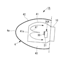
- centrifugal force acts by the rotation of the rotor head 4, and therefore, in the interior of the rotor head body 41, as shown in FIG.
- a temperature distribution is formed so that the exhaust heat of the device is accumulated and becomes high temperature in a high temperature region Th) surrounded by. That is, a temperature distribution is formed inside the rotor head main body 41 and the head cover 42 so that the temperature decreases from the central portion near the rotation axis toward the outer peripheral surface of the head cover 42.
- the exhaust heat of the in-head device generated during the operation of the wind power generator 1 has a small temperature difference between the outer surface temperature of the rotor head body 41 and the outer surface temperature of the rotor head cover 42 and the outside air temperature. It is difficult to efficiently dissipate heat from the atmosphere to the outside air. Therefore, the heat inside the rotor head main body 41 is likely to be trapped without being radiated to the outside air, and the temperature of the high temperature region Th tends to rise further to a high temperature. From such a background, in wind power generators, countermeasures for exhaust heat of the devices in the rotor head are desired.
- the present invention has been made in view of the above circumstances, and an object of the present invention is to provide a wind turbine generator that is provided with measures against exhaust heat of the devices in the rotor head.
- the present invention employs the following means.
- a rotor head that receives wind power from a windmill blade rotates a generator installed inside the nacelle to generate electric power, and the upper end of the tower in which the nacelle is erected on the foundation
- a ventilation fan that forms an air flow inside and outside the case is provided in the case of the heat generating device.
- the ventilation fan for forming the air flow inside and outside the casing is provided in the casing of the heat generating device, the exhaust heat accumulated in the casing of the heating device is ventilated.
- the internal temperature of the heat generating device can be kept low, and an air flow that agitates the inside of the rotor head body that is a sealed space is generated.
- the air temperature inside the rotor head body 41 can be leveled, and heat exchange inside and outside the rotor head body 41 can be further promoted.
- the ventilation fan is preferably arranged so as to form an air flow passing through a central portion of the rotor head body.
- a particularly heavy heating device such as a control panel is disposed near the axis of the rotor head in order to prevent eccentricity of the rotation shaft of the rotor head.
- the ventilation fan may be installed on at least one surface of the housing surface with respect to both surfaces of the rotor head in the rotation axis direction. That is, the ventilation fan installation surface of the housing is one surface that becomes the rotor head tip side in the rotation axis direction, one surface that becomes the main bearing side (nacelle side) in the rotation axis direction, or the rotor head tip side and the main shaft in the rotation axis direction. Any of both sides which become a receiving side may be sufficient.
- the ventilation fan may be a fan that blows air inside the casing of the heat generating device toward the center of the rotor head, or air inside the casing of the heat generating device on the nacelle side surface of the inner wall of the rotor head body. It is possible to use a fan that blows air toward it.
- the ventilation fan is an exhaust fan that causes the air inside the casing to flow out of the casing, and a pressure loss element is attached to an intake port of the casing.
- the pressure loss element in this case means a louver, a dust removal filter, a salt removal filter, and the like.
- exhaust heat accumulated in a heat generating device such as a control panel is ventilated to take measures against exhaust heat to keep the temperature inside the heat generating device low, and the temperature determined for the electrical components constituting the heat generating device. A high-temperature atmosphere exceeding the upper limit of the condition is prevented, and stable continuation is guaranteed.
- exhaust heat countermeasures for ventilating exhaust heat in the heat generating device to promote heat dissipation the air inside the rotor head main body is agitated and the temperature distribution is eliminated. For this reason, the temperature difference between the inside of the rotor head body and the outside of the rotor head body is increased, and heat dissipation from the rotor head body is promoted. That is, the exhaust heat in the rotor head main body is efficiently radiated to the outside, and the atmosphere in the rotor head main body is maintained at a predetermined temperature or less, so that stable operation of the heat generating device can be continued.
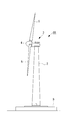
- the wind turbine generator 1 ⁇ / b> A includes a windmill tower (hereinafter referred to as “tower”) 2 erected on the foundation B, a nacelle 3 installed at the upper end of the tower 2, and a substantially horizontal position. And a rotor head 4 provided on the front end side of the nacelle 3 so as to be rotatable around a horizontal rotational axis.
- tower windmill tower
- nacelle 3 installed at the upper end of the tower 2
- a substantially horizontal position a rotor head 4 provided on the front end side of the nacelle 3 so as to be rotatable around a horizontal rotational axis.
- a plurality of (for example, three) wind turbine blades 5 are attached to the rotor head 4 in a radial pattern around its rotational axis.
- An anemometer that measures the peripheral wind speed value, an anemometer that measures the wind direction, and the like are installed at appropriate positions (for example, the upper part) of the outer surface of the nacelle 3.
- the rotor head 4 that receives wind power from the wind turbine blades 5 and rotates around a substantially horizontal rotation axis drives a generator (not shown) installed in the nacelle 3 to generate power.
- the nacelle 3 is installed at the upper end of the tower 2 erected on the foundation B so that the yaw can be turned.
- the tower 2 shown in the figure is a steel monopole type, and a cylindrical tower having a required length (height) is secured by connecting a plurality of tower section flanges (not shown).
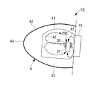
- the rotor head 4 of the wind power generator 1A described above includes, for example, a rotor head main body 41 and a head cover 42 as shown in FIG. 1A.
- the normal rotor head main body 41 is a cast part, and the outer periphery of the rotor head 41 is covered with a resin head cover 42 so as to form a space 43 around the rotor head main body 41.
- a hub control panel 20A for controlling the pitch of the wind turbine blades 5 by hydraulic pressure electrical equipment such as a control panel constituted by a large number of electrical components, and for example, a main bearing 10
- In-head devices such as drive system parts having sliding portions are installed.
- Such an in-head device is a heat generating device that generates heat as the wind power generator 1A is operated, and needs to be protected from moisture and salt according to the installation environment of the wind power generator 1. For this reason, the rotor head main body 41 has a sealed structure against the outside air.
- the control panel of the in-head device such as the hub control panel 20A is provided with a ventilation fan 30 that forms a flow in the internal air of the casing 21.
- a ventilation fan 30 is attached to one surface of a casing 21 having a rectangular parallelepiped shape.
- the pressure loss element 23 is attached to the inlet port 22 opened to the same housing
- the ventilation fan 30 is an exhaust fan that sucks out air in the housing 21 and causes the air inside the housing, whose temperature has been raised by exhaust heat, to flow out of the housing 21 (inside the rotor head body 41 of the rotor head 4).
- the operation of the ventilation fan 30 introduces the head internal air of the rotor head main body 41 into the housing 21 from the intake port 22, so that the hot internal air in the housing is relatively cool. And be ventilated.
- the ventilation fan 30 in this case is installed on the surface of the casing 21 (the surface on the left side in FIG. 1A) on the rotor head tip 4a side in the rotation axis direction of the rotor head 4.
- the casing 21 of the hub control panel 20A includes the ventilation fan 30 that forms a flow in the air inside the casing, the exhaust heat accumulated in the control panel is ventilated.
- the internal temperature can be kept low. Since the inside of the housing 21 of the hub control panel 20A is prevented from having a high temperature atmosphere exceeding the upper limit of the temperature condition defined for the component parts such as electric parts, the hub control panel 20A can continue stable operation. It becomes like this. Further, the air flow discharged out of the casing 21 agitates the interior of the rotor head main body 41. As a result, the air temperature inside the rotor head main body 41 can be leveled. There is no need to install a separate fan for each application, which is advantageous in terms of cost and installation space.
- the ventilation fan 30 of the wind power generator 1 ⁇ / b> A described above is preferably arranged so as to form an air flow passing through the central portion of the rotor head main body 41.
- a heavy heat generating device such as a control panel is disposed near the axis of the rotor head in order to prevent eccentricity of the rotation axis of the rotor head.
- FIG. 1A if the hub control panel 20A is installed on the nacelle 3 side of the rotor head main body 41 and positioned so that the rotational axis center of the ventilation fan 30 substantially coincides with the rotational axis center of the rotor head 4.
- the flow of air flowing out from the inside of the casing 21 passes through the central portion of the rotor head main body 41.
- the ventilation fan 30 installed in this way forms a circulating flow of the head internal air (broken arrow Af in the figure) in the rotor head body 41 of the rotor head 4.
- This circulating flow first flows from the nacelle 3 side toward the rotor head front end 4a side in the axial center portion in the rotor head 41, but the direction is changed by the flow path being blocked by the front end surface 41a of the rotor head body 41 Then, it is folded along the inner wall surface of the rotor head main body 41.
- the circulating flow in the rotor head main body 41 finally returns to the rear end side of the rotor head main body 41, so that the internal air of the rotor head main body 41 is effectively stirred and formed in the rotor head main body 41.
- the distributed temperature distribution is eliminated and the temperature becomes substantially uniform.
- the centrifugal force generated by the rotation of the rotor head 4 acts on the interior of the rotor head body 41 and high temperature air tends to collect in the center, the high temperature air is collected by the ventilation fan 30 of the hub control panel 20A.
- the air flow (wind) of the exhaust is directly applied and stirred, a higher stirring effect can be obtained and the temperature distribution can be made uniform.
- the wall surface temperature of the rotor head main body 41 also rises, and the outer surface temperature of the rotor head main body 41 and the space 43 The temperature difference from the inside also increases. Further, since the air temperature in the space 43 is substantially the same as the temperature of the outside air outside the head cover 42, the temperature difference between the temperature of the air inside the head and the outer surface temperature of the rotor head body 41 and the outside air also increases. .
- the air temperature inside the housing of the hub control panel 20A ventilated by the ventilation fan 30 can be ventilated with cooler air. Therefore, it becomes easy to maintain the air inside the housing at a predetermined temperature or less, and the continuation of the operation of the hub control panel 20A becomes even more stable. Further, since the air flow along the inner wall surface of the rotor head body 41 increases the flow velocity (surface flow velocity) of the air flow flowing along the inner wall surface of the rotor head body 41, the heat transfer performance is improved as the surface flow velocity increases. Also, the cooling of the air inside the head can be promoted.
- the temperature distribution of the air inside the head is made uniform, so that the rotor An exhaust heat countermeasure that increases the temperature difference between the inner wall surface of the head main body 41 and the outside air and increases the heat exchange amount inside and outside the rotor head main body 41 can also be obtained.
- the temperature inside the casing is prevented from increasing, and the hub control panel 20A installed in the rotor head 4 can be stably operated.
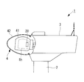
- the wind power generator 1B of this embodiment differs in the position of the ventilation fan 30 installed in the hub control panel 20B in the rotor head body 41. That is, the ventilation fan 30 is installed on the surface that is on the main bearing 10 side (nacelle 3 side) in the rotation axis direction with respect to the casing 21 of the hub control panel 20B.
- the position of the ventilation fan 30 is arrange
- the air flow in the direction of the rotation axis in the present embodiment is opposite to that in the above-described embodiment, and the flow toward the main bearing 10 side is the main flow as indicated by the broken line arrow Af in the figure.
- the ventilation fan 30 in this case also employs an exhaust fan similar to the above-described embodiment. The air flow from the ventilation fan 30 installed in this way changes its direction by being blocked by the inner wall of the rotor head 41 on the main bearing 10 side, and is turned back along the inner wall surface of the rotor head body 41. Then, a circulating flow passes from the tip of the rotor head body 41 to the center of the rotor head body 41.
- the above-described circulating flow causes the head to flow. Since the internal air is agitated efficiently and the temperature distribution is made uniform, it is possible to obtain a countermeasure against exhaust heat that increases the amount of heat exchange inside and outside the rotor head body 41. As a result, the temperature inside the casing is prevented from increasing, and the hub control panel 20B installed in the rotor head 4 can be stably operated.
- symbol is attached
- the number of ventilation fans 30 installed on the hub control panel 20C in the rotor head body 41 is different. That is, the ventilation fan 30 is provided on both the surface on the rotor head tip 4a side in the rotation axis direction and the surface on the main bearing 10 side (nacelle 3 side) in the rotation axis direction with respect to the casing 21 of the hub control panel 20C. is set up.
- the position of the ventilation fan 30 is preferably arranged so as to form an air flow in the rotation axis direction inside the rotor head main body 41 as in the above-described embodiment.
- the air flow in the direction of the rotation axis in the present embodiment is in the same direction as in the first embodiment, and the flow toward the rotor head tip 4a side is the mainstream as indicated by a broken line arrow Af in the drawing.
- the ventilation fan 30 in this case also employs an exhaust fan similar to the above-described embodiment.
- the circulating flow of air inside the head Since the temperature distribution of the air is made uniform, it is possible to obtain a measure for exhaust heat that increases the amount of heat exchange inside and outside the rotor head body 41. As a result, the temperature inside the casing is prevented from increasing, and the hub control panel 20C installed in the rotor head 4 can be stably operated.
- the position of the intake port is not particularly limited, and one or a plurality of intake positions may be provided at appropriate positions of the housing 21.
- the ventilation fan 30 of the present embodiment may be installed on at least one surface with respect to both surfaces of the casing 21 in the rotation axis direction. That is, the installation surface of the ventilation fan 30 in the casing 21 is one surface that is the rotor head tip 4a side in the rotation axis direction, one surface that is the main bearing 10 side in the rotation axis direction, or the rotor head tip 4a side in the rotation axis direction. And either of both surfaces which become the main bearing 10 side may be sufficient.
- the ventilation fan of embodiment mentioned above was made into the exhaust fan which discharges
- a suction fan may be employed.
- this invention is not limited to embodiment mentioned above, In the range which does not deviate from the summary, it can change suitably.
- Wind turbine generator 1A to 1C Wind turbine generator 2 Tower 3 Nacelle 4 Rotor head 4a Tip of rotor head 5 Wind turbine blade 10 Main bearing 20A to 20C Hub control panel (control panel) 21 Housing 22 Inlet 23 Pressure Loss Element 30 Ventilation Fan 41 Rotor Head Body 42 Head Cover
Landscapes
- Engineering & Computer Science (AREA)
- Life Sciences & Earth Sciences (AREA)
- Sustainable Development (AREA)
- Sustainable Energy (AREA)
- Chemical & Material Sciences (AREA)
- Combustion & Propulsion (AREA)
- Mechanical Engineering (AREA)
- General Engineering & Computer Science (AREA)
- Wind Motors (AREA)
- Motor Or Generator Cooling System (AREA)
- Structures Of Non-Positive Displacement Pumps (AREA)
Priority Applications (2)
| Application Number | Priority Date | Filing Date | Title |
|---|---|---|---|
| CN201280009607.5A CN103380296B (zh) | 2011-02-25 | 2012-02-09 | 风力发电装置 |
| US13/449,554 US8502407B2 (en) | 2011-02-25 | 2012-04-18 | Wind power generating apparatus |
Applications Claiming Priority (2)
| Application Number | Priority Date | Filing Date | Title |
|---|---|---|---|
| JP2011-040368 | 2011-02-25 | ||
| JP2011040368A JP5449235B2 (ja) | 2011-02-25 | 2011-02-25 | 風力発電装置 |
Related Child Applications (1)
| Application Number | Title | Priority Date | Filing Date |
|---|---|---|---|
| US13/449,554 Continuation US8502407B2 (en) | 2011-02-25 | 2012-04-18 | Wind power generating apparatus |
Publications (1)
| Publication Number | Publication Date |
|---|---|
| WO2012114891A1 true WO2012114891A1 (ja) | 2012-08-30 |
Family
ID=46720676
Family Applications (1)
| Application Number | Title | Priority Date | Filing Date |
|---|---|---|---|
| PCT/JP2012/053015 Ceased WO2012114891A1 (ja) | 2011-02-25 | 2012-02-09 | 風力発電装置 |
Country Status (4)
| Country | Link |
|---|---|
| US (1) | US8502407B2 (cg-RX-API-DMAC7.html) |
| JP (1) | JP5449235B2 (cg-RX-API-DMAC7.html) |
| CN (1) | CN103380296B (cg-RX-API-DMAC7.html) |
| WO (1) | WO2012114891A1 (cg-RX-API-DMAC7.html) |
Families Citing this family (3)
| Publication number | Priority date | Publication date | Assignee | Title |
|---|---|---|---|---|
| US9657719B2 (en) | 2014-06-16 | 2017-05-23 | General Electric Company | Ventilation arrangement |
| US20180038351A1 (en) * | 2016-08-05 | 2018-02-08 | Siemens Aktiengesellschaft | Wind turbine with improved cooling |
| CN108843524B (zh) * | 2018-06-22 | 2020-04-10 | 北京金风科创风电设备有限公司 | 用于风力发电机组的散热系统及风力发电机组 |
Citations (4)
| Publication number | Priority date | Publication date | Assignee | Title |
|---|---|---|---|---|
| JPH11178282A (ja) * | 1997-12-12 | 1999-07-02 | Railway Technical Res Inst | 通風冷却式回転電機の鉄粉除去装置 |
| JP2000166177A (ja) * | 1998-11-30 | 2000-06-16 | Toyota Autom Loom Works Ltd | 電動機の冷却装置 |
| JP2001211608A (ja) * | 1999-11-15 | 2001-08-03 | Toshiba Kyaria Kk | 車両用発電機 |
| JP2009091929A (ja) * | 2007-10-05 | 2009-04-30 | Mitsubishi Heavy Ind Ltd | 風力発電装置 |
Family Cites Families (17)
| Publication number | Priority date | Publication date | Assignee | Title |
|---|---|---|---|---|
| JPS53151507U (cg-RX-API-DMAC7.html) | 1977-05-06 | 1978-11-29 | ||
| JP2001211808A (ja) | 2000-02-03 | 2001-08-07 | Sanshin Shokai:Kk | 自動噴霧方法及びその装置 |
| US7042109B2 (en) * | 2002-08-30 | 2006-05-09 | Gabrys Christopher W | Wind turbine |
| US7075192B2 (en) * | 2004-04-19 | 2006-07-11 | Northern Power Systems, Inc. | Direct drive wind turbine |
| DE102005034899A1 (de) * | 2005-07-26 | 2007-02-01 | Repower Systems Ag | Windenergieanlage mit Einzelpitcheinrichtungen |
| US7427814B2 (en) * | 2006-03-22 | 2008-09-23 | General Electric Company | Wind turbine generators having wind assisted cooling systems and cooling methods |
| PL2002120T3 (pl) * | 2006-03-25 | 2010-04-30 | Clipper Windpower Inc | System obsługi ciepła w turbinie wiatrowej |
| US20080050234A1 (en) * | 2006-05-19 | 2008-02-28 | General Compression, Inc. | Wind turbine system |
| US7594800B2 (en) * | 2006-07-31 | 2009-09-29 | General Electric Company | Ventilation assembly for wind turbine rotor hub |
| DE102006054666B4 (de) * | 2006-11-17 | 2010-01-14 | Repower Systems Ag | Schwingungsdämpfung einer Windenergieanlage |
| US8186940B2 (en) | 2007-09-05 | 2012-05-29 | General Electric Company | Ventilation arrangement |
| US20090094981A1 (en) * | 2007-10-12 | 2009-04-16 | General Electric Company | Wind turbine geothermal heating and cooling system |
| US20090206610A1 (en) * | 2008-02-15 | 2009-08-20 | Negel Martin | Cable guard and method of installation |
| PL2151833T3 (pl) * | 2008-08-07 | 2013-08-30 | Starkstrom Geraetebau Gmbh | Układ transformatorowy |
| IT1391939B1 (it) * | 2008-11-12 | 2012-02-02 | Rolic Invest Sarl | Generatore eolico |
| IT1391770B1 (it) * | 2008-11-13 | 2012-01-27 | Rolic Invest Sarl | Generatore eolico per la generazione di energia elettrica |
| IT1393937B1 (it) * | 2009-04-09 | 2012-05-17 | Rolic Invest Sarl | Aerogeneratore |
-
2011
- 2011-02-25 JP JP2011040368A patent/JP5449235B2/ja active Active
-
2012
- 2012-02-09 WO PCT/JP2012/053015 patent/WO2012114891A1/ja not_active Ceased
- 2012-02-09 CN CN201280009607.5A patent/CN103380296B/zh active Active
- 2012-04-18 US US13/449,554 patent/US8502407B2/en active Active
Patent Citations (4)
| Publication number | Priority date | Publication date | Assignee | Title |
|---|---|---|---|---|
| JPH11178282A (ja) * | 1997-12-12 | 1999-07-02 | Railway Technical Res Inst | 通風冷却式回転電機の鉄粉除去装置 |
| JP2000166177A (ja) * | 1998-11-30 | 2000-06-16 | Toyota Autom Loom Works Ltd | 電動機の冷却装置 |
| JP2001211608A (ja) * | 1999-11-15 | 2001-08-03 | Toshiba Kyaria Kk | 車両用発電機 |
| JP2009091929A (ja) * | 2007-10-05 | 2009-04-30 | Mitsubishi Heavy Ind Ltd | 風力発電装置 |
Also Published As
| Publication number | Publication date |
|---|---|
| US20120256425A1 (en) | 2012-10-11 |
| CN103380296B (zh) | 2016-08-24 |
| US8502407B2 (en) | 2013-08-06 |
| JP5449235B2 (ja) | 2014-03-19 |
| CN103380296A (zh) | 2013-10-30 |
| JP2012177326A (ja) | 2012-09-13 |
Similar Documents
| Publication | Publication Date | Title |
|---|---|---|
| CN101117942B (zh) | 用于风力涡轮机转子毂的通风装置 | |
| KR101162826B1 (ko) | 풍력 발전 장치 | |
| JP5148517B2 (ja) | 風力発電装置 | |
| JP5511549B2 (ja) | 風力発電装置 | |
| JP5211244B2 (ja) | 風力発電装置 | |
| CA2446632C (en) | Cooling device for a wind turbine generator | |
| JP5463218B2 (ja) | 風力発電装置 | |
| JP2012072684A (ja) | 風力発電装置 | |
| JP5002309B2 (ja) | 水平軸風車 | |
| JP5595057B2 (ja) | 風力発電装置 | |
| JP2007002773A (ja) | 水平軸風車 | |
| JP6650318B2 (ja) | 風力発電装置 | |
| JP5449235B2 (ja) | 風力発電装置 | |
| JP4814608B2 (ja) | 風車 | |
| JP6368559B2 (ja) | 風力発電装置 | |
| JP2015068243A (ja) | 風力発電設備 | |
| CN117167221A (zh) | 风力发电机的机舱及风力发电机组 |
Legal Events
| Date | Code | Title | Description |
|---|---|---|---|
| 121 | Ep: the epo has been informed by wipo that ep was designated in this application |
Ref document number: 12750228 Country of ref document: EP Kind code of ref document: A1 |
|
| NENP | Non-entry into the national phase |
Ref country code: DE |
|
| 122 | Ep: pct application non-entry in european phase |
Ref document number: 12750228 Country of ref document: EP Kind code of ref document: A1 |